

Page 1

INSTRUCTION MANUAL
For...は専用機種。複数の場合は「/」で区切る。
不要の場合はとる。
形名を入力。 複数の場合は「/」で区切る。
3555
品名を入力。
BATTERY HiTESTER
http://www.911618.com/
http://www.911618.com/dianchiceshiyi/HIOKI-3555/
http://www.911618.com/jishuwenzhang/HIOKI-3555/
Page 2

Contents
Introduction i
Inspection i
Safety ii
Precautions v
Organization of This Manual viii
Chapter 1 Overview 1
1.1 Product Overview 1
1.2 Features 1
Chapter 2 Names and Functions of Parts 3
Chapter 3 Specifications 9
3.1 General Specification 9
3.2 Measurement Range 12
3.2.1 Maximum Input Voltage 13
3.2.2 Dielectric Strength 14
Chapter 4 Standard Measurement 15
4.1 Preparing for Measurement 15
4.2 Measurement 16
Chapter 5 Advanced Measurement Functions 21
5.1 Comparator Function 21
5.1.1 What is the Comparator Function? 21
5.1.2 Changing the Comparator Settings
22
5.1.3 Comparator Decision Result Table
27
5.1.4 Switching the Comparator On and Off 28
5.1.5 Changing the Comparator Number
29
5.2 Beeper On/Off Function 29
Page 3

5.3 Hold Function 30
5.4 Zero Adjust Function 30
5.5 Battery Low Warning 32
5.6 Auto Power Off 33
5.7 AC Four-Terminal Method 35
Chapter 6 Maintenance 37
6.1 Troubleshooting 37
6.2 Message Reference 38
6.3 Cleaning 39
Page 4

i
――――――――――――――――――――――――――――――――――――――
Inspection
――――――――――――――――――――――――――――――――――
Introduction
Inspection
Thank you for purchasing the HIOKI "3555 BATTERY
HiTESTER." To obtain maximum performance from the
instrument, please read this manual first, and keep it
handy for future reference.
When you receive the instrument, inspect it carefully to
ensure that no damage occurred during shipping. In
particular, check the accessories, panel switches, and
connectors. If damage is evident, or if it fails to operate
according to the specifications, contact your dealer or
Hioki representative.
Accessories
9461 PIN TYPE LEAD
Six LR6 alkaline batteries
Instruction Manual
Shipping
Use the original packing materials when reshipping the
instrument, if possible.
Page 5
ii
――――――――――――――――――――――――――――――――――――――
Safety
――――――――――――――――――――――――――――――――――
DANGER
This instrument is designed to comply with IEC 61010
Safety Standards, and has been thoroughly tested for
safety prior to shipment. However, mishandling
during use could result in injury or death, as well as
damage to the instrument. Be certain that you
understand the instructions and precautions in the
manual before use. We disclaim any responsibility for
accidents or injuries not resulting directly from
instrument defects.
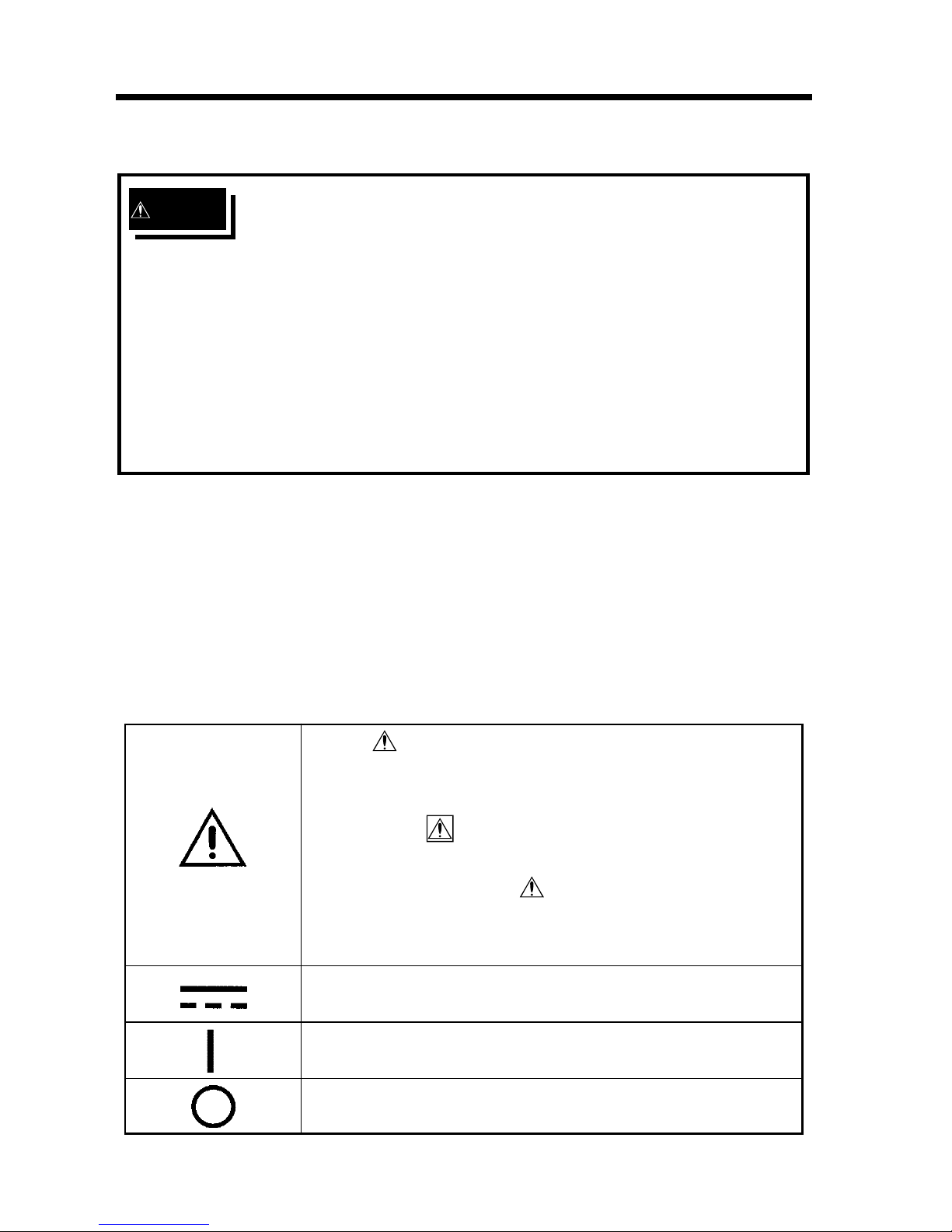
・ The symbol printed on the instrument
indicates that the user should refer to a
corresponding topic in the manual (marked
with the symbol) before using the relevant
function.
・ In the manual, the symbol indicates
particularly important information that the
user should read before using the instrument.
Indicates DC (Direct Current).
Indicates the ON side of the power switch.
Indicates the OFF side of the power switch.
Safety
Safety symbols
This manual contains information and warnings essential
for safe operation of the instrument and for maintaining
it in safe operating condition. Before using the
instrument, be sure to carefully read the following safety
notes.
Page 6
iii
――――――――――――――――――――――――――――――――――――――
Safety
――――――――――――――――――――――――――――――――――
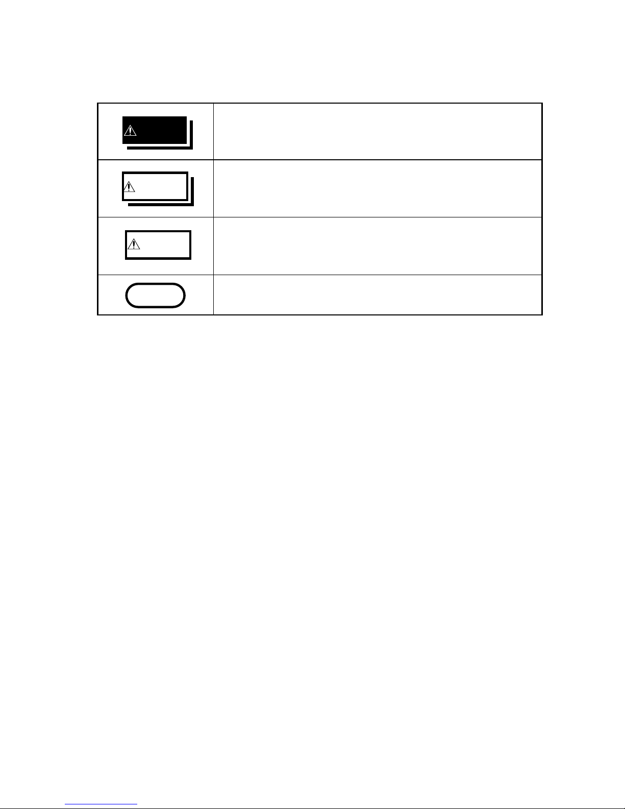
DANGER
Indicates that incorrect operation presents an
extreme hazard that could result in serious
injury or death to the user.
WARNING
Indicates that incorrect operation presents a
significant hazard that could result in serious
injury or death to the user.
CAUTION
Indicates that incorrect operation presents a
possibility of injury to the user or damage to the
instrument.
NOTE
Indicates advisory items related to performance
or correct operation of the instrument.
The following symbols in this manual indicate the relative
importance of cautions and warnings.
Page 7
iv
――――――――――――――――――――――――――――――――――――――
Safety
――――――――――――――――――――――――――――――――――
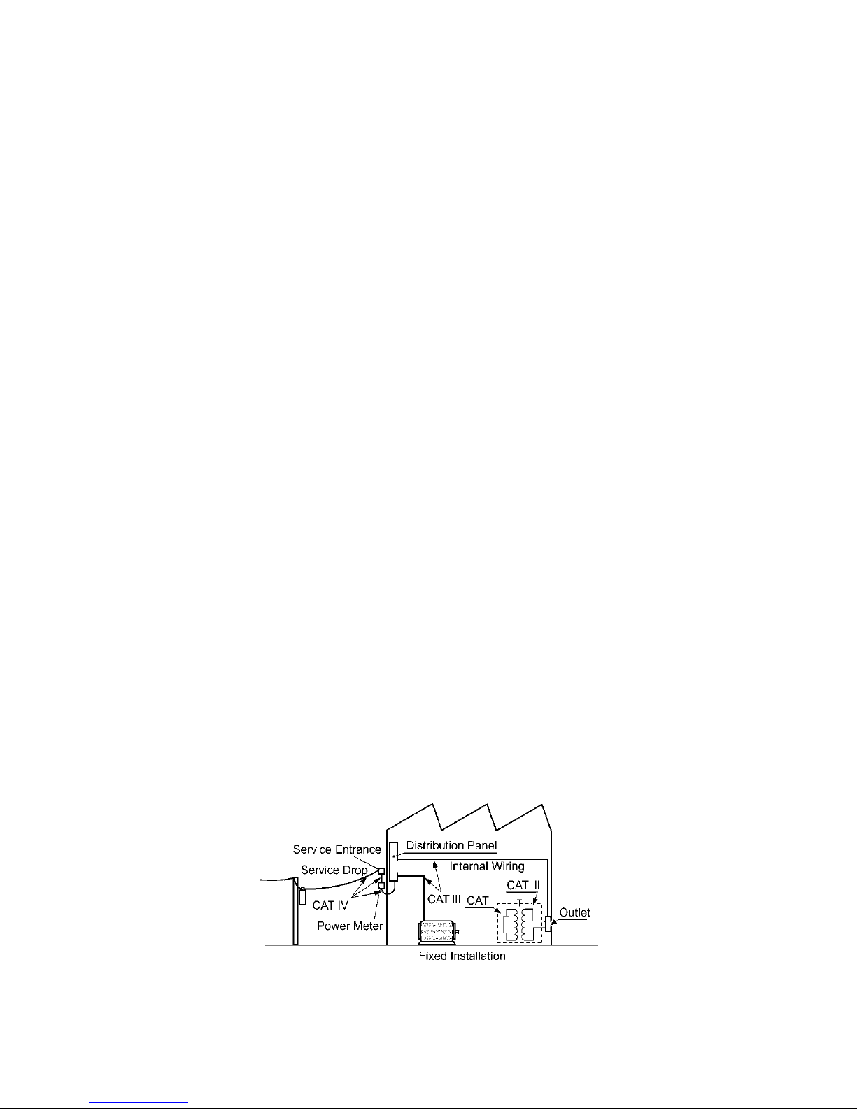
Measurement categories (Overvoltage categories)
This instrument complies with CAT I safety requirements.
To ensure safe operation of measurement instruments, IEC
61010 establishes safety standards for various electrical
environments, categorized as CAT I to CAT IV, and called
measurement categories. These are defined as follows.
CAT I : Secondary electrical circuits connected to an AC
electrical outlet through a transformer or similar
device.
CAT II : Primary electrical circuits in equipment connected
to an AC electrical outlet by a power cord
(portabletools,household appliances, etc.)
CAT III : Primary electrical circuits of heavy
equipment (fixed installations) connected directly
to the distribution panel, and feeders from the
distribution panel to outlets.
CAT IV : The circuit from the service drop to the service
entrance, and to the power meter and primary
overcurrent protection device (distribution panel).
Higher-numbered categories correspond to electrical
environments with greater momentary energy. So a
measurement device designed for CAT III environments can
endure greater momentary energy than a device designed
for CAT II.
Using a measurement instrument in an environment
designated with a higher-numbered category than that for
which the instrument is rated could result in a severe
accident, and must be carefully avoided.
Never use a CAT I measuring instrument in CAT II, III, or
IV environments.
The measurement categories comply with the Overvoltage
Categories of the IEC60664 Standards.
Page 8
v
――――――――――――――――――――――――――――――――――――――
Precautions
――――――――――――――――――――――――――――――――――
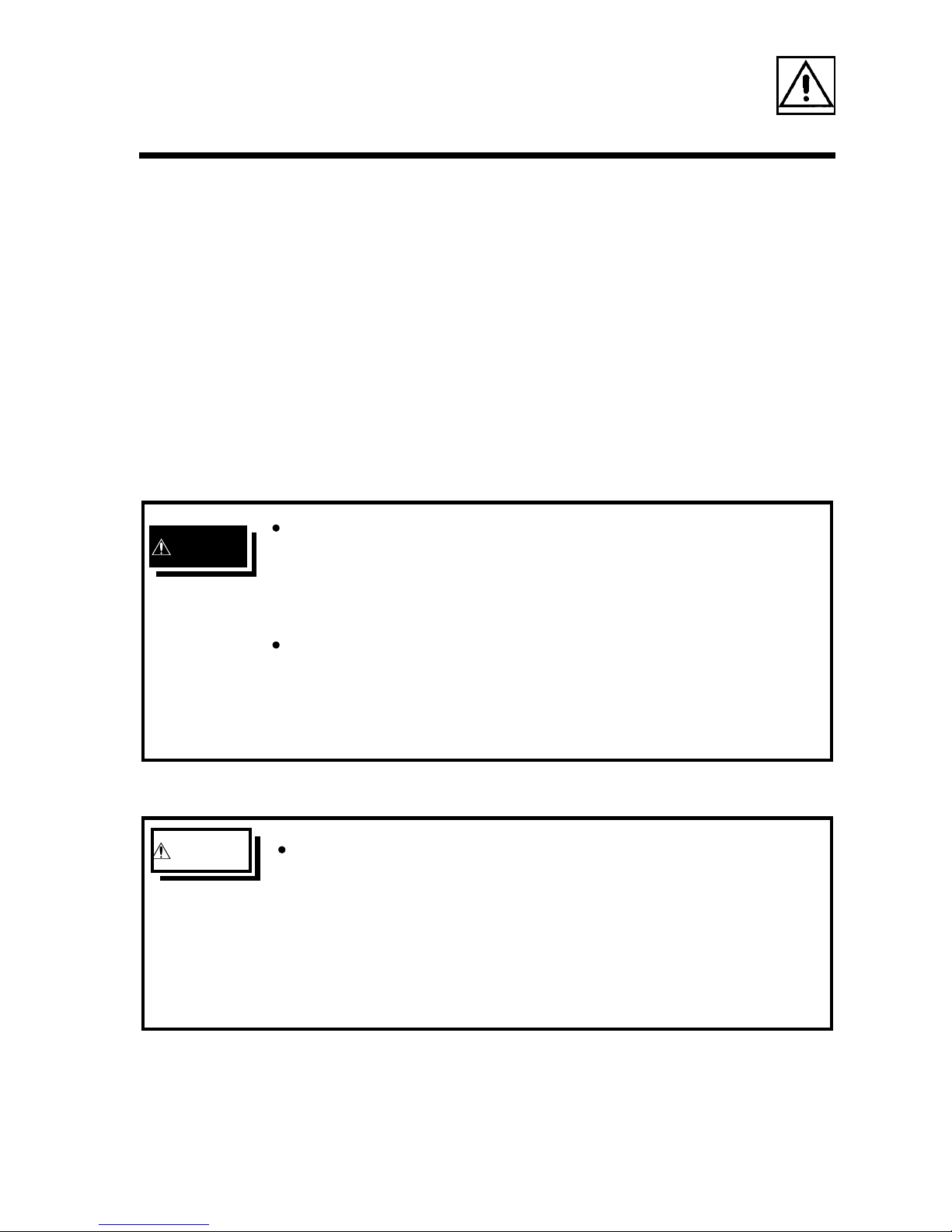
DANGER
The floating voltage between input terminals and
ground is 60 V AC/DC. Do not attempt to measure
voltages exceeding 60 V with respect to ground. This
could result in injury or damage to the instrument.
When measuring batteries, always ensure sufficient
ventilation. Sometimes sparks may occur when the
test leads are connected to batteries, which can ignite
any accumulated inflammable gases such as hydrogen
.
WARNING Before using the instrument, make sure that the
insulation on the test leads is undamaged and that no
bare conductors are improperly exposed. Using the
instrument in such conditions could cause an electric
shock, so contact your dealer or Hioki representative
for replacements (Model 9461, Model 9287-10).
Precautions
Follow these precautions to ensure safe operation and to
obtain the full benefits of the various functions.
Preliminary Check
Before using the instrument the first time, verify that it
operates normally to ensure that the no damage occurred
during storage or shipping. If you find any damage,
contact your dealer or Hioki representative.
Page 9
vi
――――――――――――――――――――――――――――――――――――――
Precautions
――――――――――――――――――――――――――――――――――
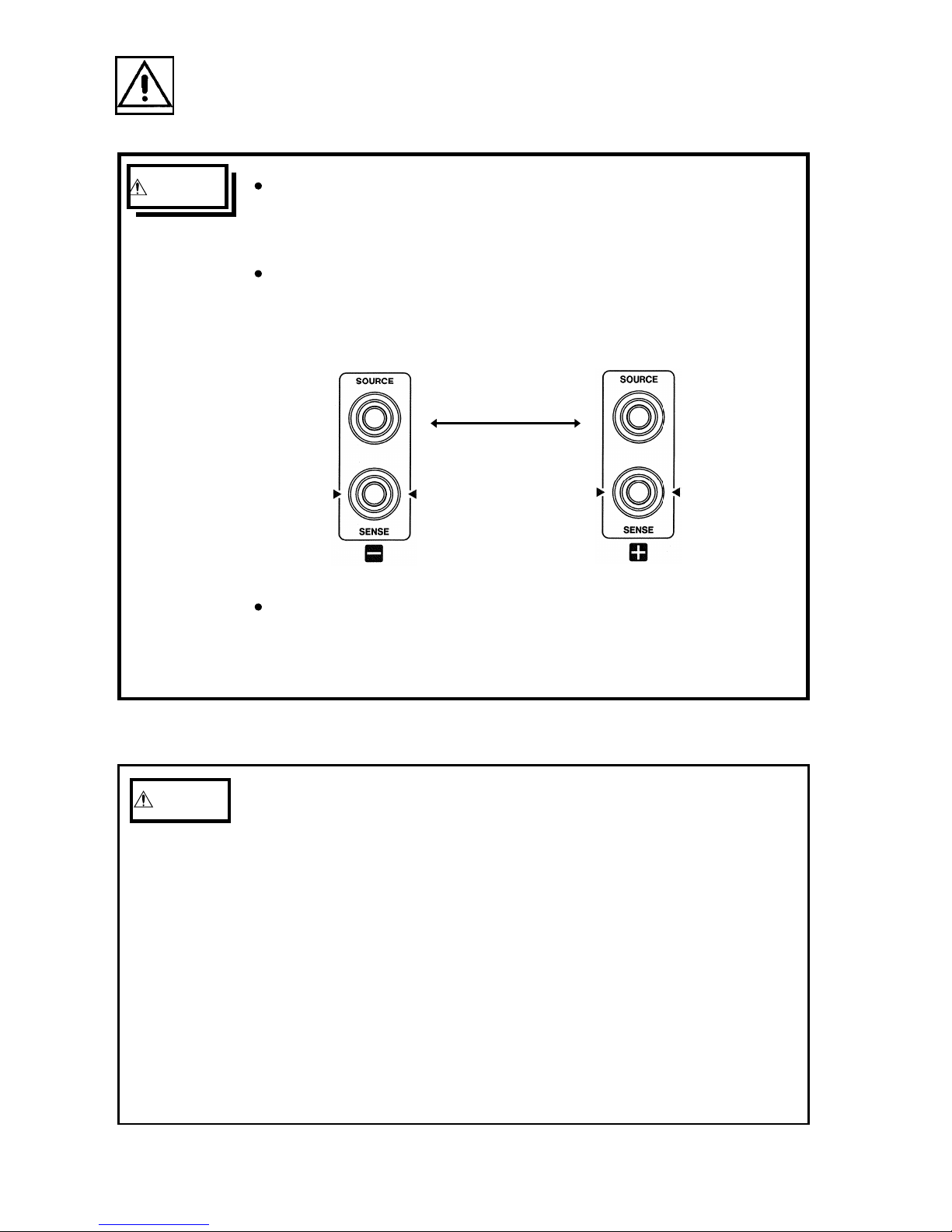
WARNING Be sure to connect the SOURCE and SENSE terminals
correctly. See Section 4.2, "Measurement" for details
of the connections.
To avoid injury or damage to the instrument, do not
attempt to measure AC voltage, or DC voltage
exceeding 50 V.
50 VDC max
Do not apply a voltage between the SOURCE(+) and
SENSE(+) or SOURCE(-) and SENSE(-) terminals. This
could result in damage to the instrument.
CAUTION
・ This instrument is not designed to be entirely water- or
dust-proof. To avoid damage, do not use it in a wet or
dusty environment.
・ Do not store or use the instrument where it could be
exposed to direct sunlight, high temperature or
humidity, or condensation. Under such conditions, the
instrument may be damaged and insulation may
deteriorate so that it no longer meets specifications.
・ Do not use the instrument near a source of strong
electromagnetic radiation, or near a highly electrically
charged object. These may cause a malfunction.
Page 10

vii
――――――――――――――――――――――――――――――――――――――
Precautions
――――――――――――――――――――――――――――――――――
NOTE
・ Correct measurement may be impossible in the presence
of strong magnetic fields, such as near transformers
and high-current conductors, or in the presence of
strong electromagnetic fields such as near radio
transmitters.
・ For safety reasons, when taking measurements, only
use the 9461 PIN TYPE LEAD provided with the
instrument, or the optional 9287-10 CLIP TYPE LEAD.
Service
・ When sending the instrument for repair, remove the
batteries and pack carefully to prevent damage in transit.
Include cushioning material so the instrument cannot
move within the package. Be sure to include details of the
problem. Hioki cannot be responsible for damage that
occurs during shipment.
Page 11

viii
――――――――――――――――――――――――――――――――――――――
Organization of This Manual
――――――――――――――――――――――――――――――――――
Organization of This Manual
This manual consists of the following chapters.
"Introduction", "Inspection", "Safety", "Precautions"
include some important notes which you should read
before using the instrument.
Chapter 1 Overview
describes an outline of the instrument, and lists its
features.
Chapter 2 Names and Functions of Parts
lists the names of the parts of the instrument, and the
functions of all of the indications, terminals, and
switches.
Chapter 3 Specifications
lists the specifications of the instrument.
Chapter 4 Standard Measurement
describes the basic operation of the instrument.
Chapter 5 Advanced Measurement Functions
describes miscellaneous functions.
Chapter 6 Maintenance
gives troubleshooting information.
Page 12

1
――――――――――――――――――――――――――――――――――――――
Chapter 1 Overview
――――――――――――――――――――――――――――――――――
Chapter 1
Overview
1.1 Product Overview
1.2 Features
The 3555 is designed for measuring the internal
resistance and open-circuit voltage of secondary batteries,
including lead storage cells, nickel-cadmium batteries,
nickel-metal hydride batteries, and lithium-ion batteries.
(1) Since it uses the AC four-terminal method to measure the
internal resistance, it provides accurate results with the
lead resistances and contact resistances eliminated.
(2) It is possible to display the readings for the battery
internal resistance and voltage without changing
functions.
(3) A composite comparator function, which can be set on
resistance and voltage values, enables reliable detection
of battery deterioration.
(4) Pin type leads which can easily contact the battery
electrodes are supplied as standard, allowing highaccuracy four-terminal measurement.
http://www.911618.com/
http://www.911618.com/dianchiceshiyi/HIOKI-3555/
http://www.911618.com/jishuwenzhang/HIOKI-3555/
Page 13

2
――――――――――――――――――――――――――――――――――――――
Chapter 1 Overview
――――――――――――――――――――――――――――――――――
Page 14

3
――――――――――――――――――――――――――――――――――――――
Chapter 2 Names and Functions of Parts
――――――――――――――――――――――――――――――――――
Chapter 2
Names and Functions
of
Parts
This chapter explains the keys, input and output
terminals, display, LED indicators, and leads.
Page 15
4
――――――――――――――――――――――――――――――――――――――
Chapter 2 Names and Functions of Parts
――――――――――――――――――――――――――――――――――
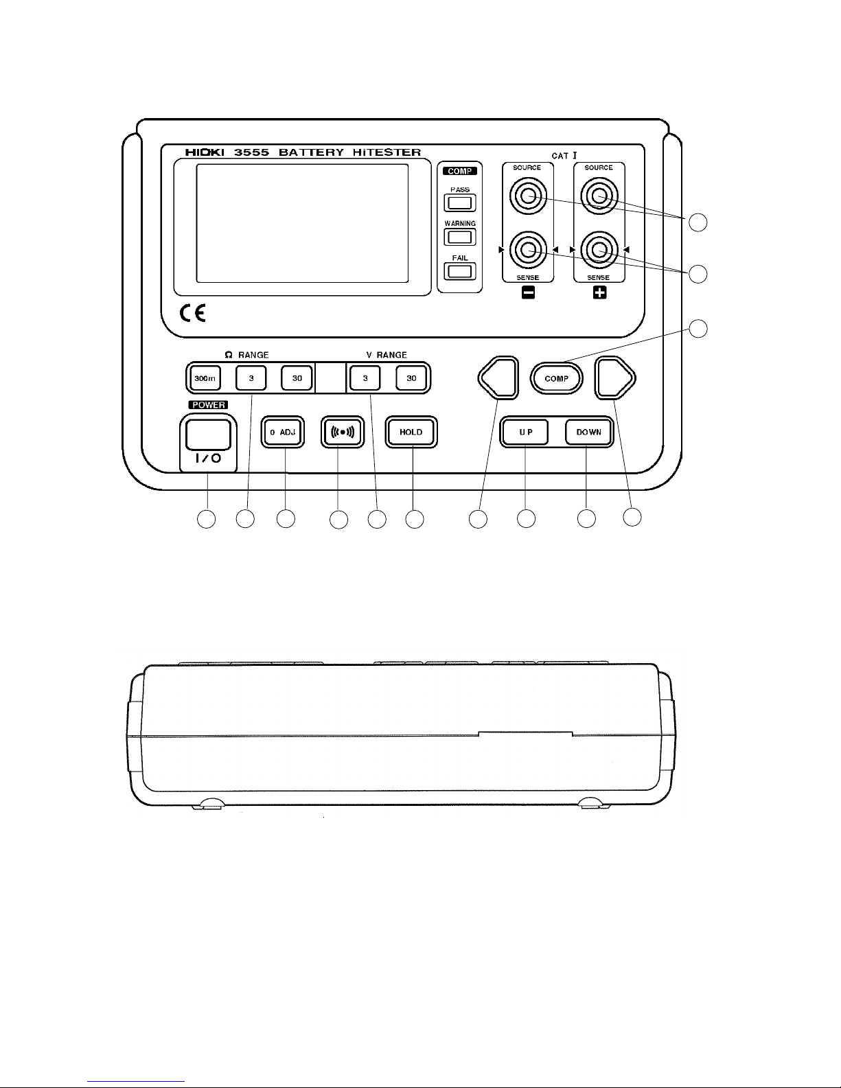
Front panel
Side panel
1
2
3
4
5
6
7
9
10 11
8
13
12
Page 16
5
――――――――――――――――――――――――――――――――――――――
Chapter 2 Names and Functions of Parts
――――――――――――――――――――――――――――――――――
1
Selects the resistance range.
Selects the voltage range.
2
3
4
5
6
7
8
9
10
11
12
13
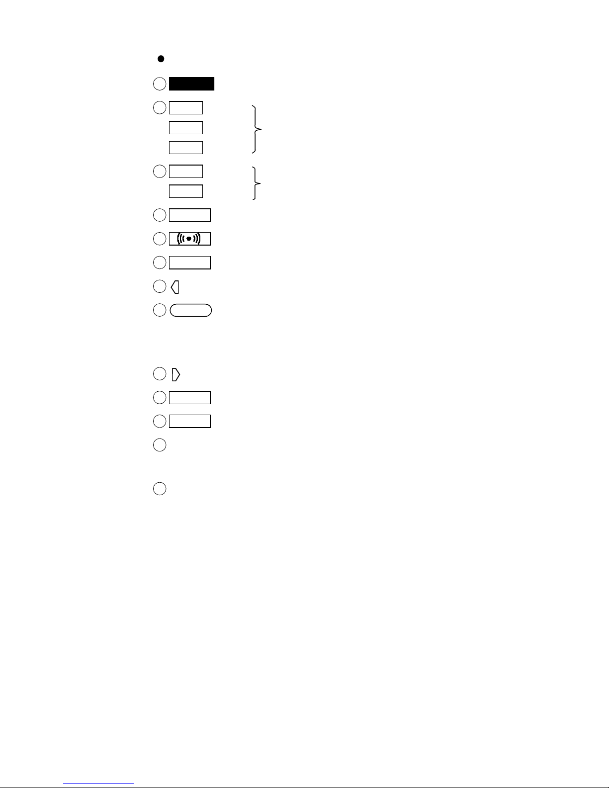
Keys and input/output terminals
POWER
key Turns the power on or off.
300m
Ω key
3
Ω key
30
Ω key
3
V key
30
V key
0 ADJ
key Zero adjustment key
key Turns the beeper on and off.
HOLD
key Locks out changes to the display.
key Left cursor (flashing) key
COMP
key Switches the comparator on and off, and
changes display to the comparator setting
screen.
key Right cursor (flashing) key
UP
key Increases the value of a numeric setting.
DOWN
key Decreases the value of a numeric setting.
SOURCE
Connects to the 9461 banana plug on the
SOURCE side.
SENSE Connects to the 9461 banana plug on the
SENSE side.
Page 17
6
――――――――――――――――――――――――――――――――――――――
Chapter 2 Names and Functions of Parts
――――――――――――――――――――――――――――――――――
1
2
3
1
2
3
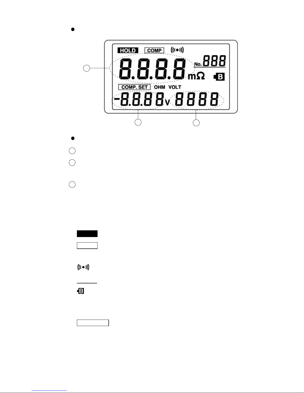
LCD
(view with all elements displayed)
Display
Measured resistance
Measured voltage [comparator resistance upper limit
setting and comparator voltage setting]
[Comparator resistance lower limit setting]
[]: Appears in on the comparator setting screen
mΩ Indicates the unit of resistance.
V Indicates the unit of voltage.
HOLD
Appears when the display is locked.
COMP
Appears when the comparator function is
on.
Appears when the beeper is turned on.
No.
The comparator table number.
Appears when the battery voltage of the
tester is low, to prompt the user to replace
the battery.
COMP.SET
Appears during display of the comparator
setting screen.
Page 18

7
――――――――――――――――――――――――――――――――――――――
Chapter 2 Names and Functions of Parts
――――――――――――――――――――――――――――――――――
OHM
Appears during display of the screen for
setting the comparator resistance upper
and lower limit values.
VOLT
Appears during display of the screen for
setting the comparator voltage threshold
value.
LEDs
PASS Indicates that the tested battery is
satisfactory for operation.
WARNING
Indicates that the tested battery is
beginning to deteriorate.
FAIL
Indicates that the tested battery has
deteriorated.
These indications appear when the upper and lower
comparator limits for internal resistance and the
comparator threshold value for voltage are all set.
Page 19

8
――――――――――――――――――――――――――――――――――――――
Chapter 2 Names and Functions of Parts
――――――――――――――――――――――――――――――――――
SOURCE SENSE
Probe (red)
Probe (black)
Banana plug (black)
Banana plug (red)
CAUTION
The ends of the 9461 PIN TYPE LEAD are sharp. Be
careful to avoid injury.
9461 PIN TYPE LEAD
http://www.911618.com/
http://www.911618.com/dianchiceshiyi/HIOKI-3555/
http://www.911618.com/jishuwenzhang/HIOKI-3555/
Page 20

9
――――――――――――――――――――――――――――――――――――――
Chapter 3 Specifications
――――――――――――――――――――――――――――――――――
Chapter 3
Specifications
3.1 General Specification
■ Measurement method Resistance: AC four-terminal
method
■
A/D conversion Double integration method
■
Display LCD and LEDs (comparator
output)
■ Panel abbreviations
HOLD,COMP
, ,
No.
,m, Ω,
and symbols ,
COMP.SET
, OHM, VOLT, V
■
Sampling rate 1.25 sets (resistance and voltage
measurements)/second
■
Open-circuit terminal 5 V max.
voltage
■ Input overflow "OF" indication
■
Battery low detection " " indication (indicates at 6.4 V
with LR6 ×6)
■
Constant current fault "----" indication
detection
■ Auto power off Power off automatically after
about 30 minutes.
■
Zero adjustment function Circuit offset voltage is displayed
as 0 V.
■
Hold function Display is held.
■ Beeper function Audible output for warning and
fail results
Can be turned on and off.
Page 21

10
――――――――――――――――――――――――――――――――――――――
Chapter 3 Specifications
――――――――――――――――――――――――――――――――――
Resistance
Voltage
LO IN HI
LO
WARNING
(Amber)*1
WARNING
(Amber)
FAIL
(Red)
HI
PASS
(Green)
WARNING
(Amber)
FAIL
(Red)
■
Comparator settings Resistance upper and lower limits
and voltage lower limit
■
Number of comparator Ten sets
settings
■ Comparator output LEDs for pass (green), warning
(amber), and fail (red) results
Audible tone for warning and fail
results
*1
Voltage low and internal resistance low: amber flashing
■
Operating temperature 0℃ to 40℃(32。F to 104。F) 80% RH
and humidity range (no condensation)
■
Storage temperature -10℃ to 50℃(14。F to 122。F)
and humidity range 80% RH (no condensation)
■
Power source Six LR6 alkaline batteries or
six R6P manganese batteries
■ Rated supply voltage 1.5 VDC×6 (Voltage fluctuations
of 10% from the rated supply
voltage are taken into account.)
■
Maximum value usable 2000 m or less
■
Maximum power 1.0 VA
consumption
■
Continuous operating Approx. 18 hours (at 300 mΩ range,
time comparator ON, beeper ON, with
LR6 batteries)
■ Dimensions Approx.196W×130H×50D mm
(7.72"W×5.12"H×1.97"D)
■
Mass Approx. 680 g (25 oz)
(including batteries)
Page 22

11
――――――――――――――――――――――――――――――――――――――
Chapter 3 Specifications
――――――――――――――――――――――――――――――――――
■
Effect of radiated at 3V/m
radio-frequency Resistance measurement
electromagnetic field ±3.0%f.s.
Voltage measurement
±3.0% f.s.
■
Standards applying
EMC EN61326 :1997+A1:1998+A2:2001
+A3:2003
Safety EN61010-1:2001
Pollution Degree 1,
Measurement Category I
(anticipated transient overvoltage330 V)
■
Accessories 9461 PIN TYPE LEAD
Instruction Manual
Six LR6 alkaline batteries
■ Options 9287-10 CLIP TYPE LEAD
9452 CLIP TYPE LEAD
9453 FOUR TERMINAL LEAD
9770 PIN TYPE LEAD
9771 PIN TYPE LEAD
9382 CARRYING CASE
Accuracy
We define measurement tolerances in terms of f.s. (full
scale), rdg. (reading) and dgt. (digit) values, with the
following meanings:
f.s. (maximum display value or scale length)
The maximum displayable value or the full length of the scale.
This is usually the maximum value of the currently selected range.
rdg. (reading or displayed value)
The value currently being measured and indicated on the
measuring instrument.
dgt. (resolution)
The smallest displayable unit on a digital measuring
instrument, i.e., the input value that causes the digital
display to show a "1".
Page 23

12
――――――――――――――――――――――――――――――――――――――
Chapter 3 Specifications
――――――――――――――――――――――――――――――――――
Range
Maximum
indication
Resolution
Measurement
current
Accuracy
300 mΩ 300.0 mΩ 100 μΩ 5mA
Six months ±0.8% rdg.±6dgt.
1 year ±1.2% rdg.±6dgt.
3 Ω 3.000 mΩ 1mΩ 500 μA
Six months ±0.8% rdg.±6dgt.
1 year ±1.2% rdg.±6dgt.
30 Ω 30.00 Ω 10 mΩ 50 μA
Six months ±0.8% rdg.±6dgt.
1 year ±1.2% rdg.±6dgt.
Range
Maximum
indication
Resolution Accuracy
3V ±3.000 V 1mV
Six months ±0.1% rdg.±6 dgt.
1 year ±0.15% rdg.±6 dgt.
30 V ±30.00 V 10 mV
Six months ±0.1% rdg.±6 dgt.
1 year ±0.15% rdg.±6 dgt.
3.2 Measurement Range
Conditions to guarantee accuracy:
・ Temperature 23℃±5℃
・ Humidity 80% RH or less (no condensation)
・ Zero adjustment After zero adjustment for each
range
・ Warming up time At least 10 minutes
・ Period of guaranteed accuracy 1 year
(1) Resistance Measurement
Temperature coefficient: (±0.01% rdg.±0.5 dgt.)/℃
Measurement current frequency: 1 kHz±5Hz
(2) Voltage Measurement
Temperature coefficient: (±0.005% rdg.±0.5dgt.)/℃
Page 24

13
――――――――――――――――――――――――――――――――――――――
Chapter 3 Specifications
――――――――――――――――――――――――――――――――――
DANGER
The maximum input voltage is 50V DC. Attempting
to measure voltage in excess of the maximum input
could destroy the instrument and result in personal
injury or death.
To avoid electrical hazards and damage to the
instrument, do not apply voltage exceeding the
maximum input to the measurement terminals.
50 V DC max
50 V DC maximum
No AC voltage input
Between input terminals and ground, 60 V DC and AC
maximum
3.2.1 Maximum Input Voltage
Page 25

14
――――――――――――――――――――――――――――――――――――――
Chapter 3 Specifications
――――――――――――――――――――――――――――――――――
DANGER
350 Vrms max
for 1 minute
Between input terminals and case:
350 V rms for 1 minute.
3.2.2 Dielectric Strength
http://www.911618.com/
http://www.911618.com/dianchiceshiyi/HIOKI-3555/
http://www.911618.com/jishuwenzhang/HIOKI-3555/
Page 26

15
――――――――――――――――――――――――――――――――――――――
Chapter 4 Standard Measurement
――――――――――――――――――――――――――――――――――
WARNING
To avoid electric shock when replacing the
batteries, first disconnect the test leads from the
object to be measured.
Do not mix old and new batteries, or different types
of batteries. Also, be careful to observe battery
polarity during installation. Otherwise, poor
performance or damage from battery leakage could
result.
After replacing the batteries, replace the cover
before using the instrument.
Chapter 4
Standard Measurement
4.1 Preparing for Measurement
1. Remove the battery cover.
2. Insert the batteries into the battery compartment as
shown in the figure below.
Page 27

16
――――――――――――――――――――――――――――――――――――――
Chapter 4 Standard Measurement
――――――――――――――――――――――――――――――――――
WARNING To avoid the possibility of explosion, do not short
circuit, disassemble or incinerate batteries.
Handle and dispose of batteries in accordance with
local regulations.
NOTE
WARNING To avoid injury or damage to the instrument, do not
attempt to measure AC voltage, or DC voltage
exceeding 50 V.
4.2 Measurement
・ The " " indicator appears when battery voltage becomes
low. Replace the batteries as soon as possible.
・ After replacing the batteries, the auto power off function
is set to 30 minutes, with the beeper on.
・ Be sure to press the
POWER
key to power the instrument
off before removing the batteries. If the batteries are
removed while the instrument is powered on, the previous
comparator number may not be recovered.
・ To avoid problems with battery operation, remove the
batteries from the instrument if it is to be stored for a
week or more.
Even when the power to the main instrument is switched
off, a very small current (approximately 0.7 mA) is drawn
from the batteries to back up internal data. Therefore if
the instrument is left switched off with new batteries
installed, they will become fully drained within 2 to 2.5
months.
Page 28

17
――――――――――――――――――――――――――――――――――――――
Chapter 4 Standard Measurement
――――――――――――――――――――――――――――――――――
CAUTION
・ Do not attempt to measure the voltage of a generator.
This would result in an AC voltage being applied to the
voltage-generating output terminals, which is
dangerous.
・ After measuring a high-voltage battery, before
continuing to measure a low-voltage battery first short
the test leads together. This will discharge the DCelimination capacitor which is connected across the
leads. Otherwise an excess voltage may be applied to
the low-voltage battery, which is dangerous.
RedBlack
1. Connect the 9461 PIN TYPE LEAD as shown in the
figure below. Connect leads to all four terminals;
SOURCE +/− and SENSE +/−.
2. Press the
POWER
key to turn on the power and start
measurement.
After pressing the
POWER
key to power on, it is necessary
to wait for ten minutes of warming-up time, to allow the
instrument to stabilize.
Page 29

18
――――――――――――――――――――――――――――――――――――――
Chapter 4 Standard Measurement
――――――――――――――――――――――――――――――――――
Black
Red
Battery
At rest During measuring
Battery
SOURCE
SENSE
3. Contact the red probe of the 9461 with the positive
battery terminal, and the black probe with the negative
terminal.
As shown in the figure below, the outer shield conductors
of the leads are connected to the SOURCE terminals, and
the inner pin conductors are connected to the SENSE
terminals. When contacting the probes with the battery
terminals, press so that the inner pin conductors are
pushed inside, and all of the SOURCE and SENSE
conductors make good contact.
Page 30

19
――――――――――――――――――――――――――――――――――――――
Chapter 4 Standard Measurement
――――――――――――――――――――――――――――――――――
NOTE
4. Using the range keys, select the voltage and resistance
measurement ranges.
5. When the measurement is completed, disconnect the leads
from the tested battery and press the
POWER
key to turn
off the power.
・ When measuring the contact resistance of a relay or
connector, be careful of the open-circuit voltage across the
test leads. It may not always be possible to destroy an
oxide layer on the terminals of the object being measured
in order to obtain an accurate reading.
・ When the indication for a measurement value is "OF",
this indicates that the measured voltage or resistance
value is outside the measurement range.
Page 31

20
――――――――――――――――――――――――――――――――――――――
Chapter 4 Standard Measurement
――――――――――――――――――――――――――――――――――
・ A resistance indication "----" means that the measurement
could not be made because there is a break in the test
lead circuit. The "----" indication may also appear if the
leads are not making good contact with the object to be
measured, or if its resistance is extremely large compared
with the measurement range.
・ The "----" indication may also appear immediately after
changing the resistance or voltage measurement range.
・ Except for setting the auto power off mode, do not press
the
POWER
key in combination with other keys. (For
details of the auto power off settings, see Section 5.6,
"Auto Power Off.")
・ If you do press a combination of the
POWER
key and other
keys, and an "INSP" or "Adju" indication appears,
immediately press the
POWER
key to power off and on
again. Otherwise, continuing with key operations may
destroy the calibration data for the instrument, and
correct measurement will no longer be possible.
・ If the leads are open-circuit, a spurious voltage indication
may sometimes be given. This is not a malfunction.
Page 32

21
――――――――――――――――――――――――――――――――――――――
Chapter 5 Advanced Measurement Functions
――――――――――――――――――――――――――――――――――
Chapter 5
Advanced Measurement
Functions
5.1 Comparator Function
5.1.1 What is the Comparator Function?
The comparator function compares the measurement
values with preset lower and upper limit values for
internal resistance and voltage level, and determines
which range the measurement falls into, based on the
following conditions. It then lights the corresponding
LED, and sounds a beeper for the WARNING and FAIL
cases. (Refer to Section 5.2, "Beeper On/Off Function.")
Page 33

22
――――――――――――――――――――――――――――――――――――――
Chapter 5 Advanced Measurement Functions
――――――――――――――――――――――――――――――――――
Lower resistance limit Upper resistance limit
Comparator
number
Resistanc
e
range
5.1.2 Changing the Comparator Settings
(1) Before changing the settings
To change the comparator settings (upper and lower
resistance limits and voltage comparison value), do the
following:
1. Press and hold the
COMP
key for at least 3 seconds. The
upper and lower resistance limit settings appear.
2. "COMP.SET" appears at the lower left of the screen,
showing that you are ready to change the comparator
settings.
Page 34

23
――――――――――――――――――――――――――――――――――――――
Chapter 5 Advanced Measurement Functions
――――――――――――――――――――――――――――――――――
(2) Setting the comparator number
When the comparator setting screen appears, set the
comparator number corresponding to the battery to be
tested.
1. Using the and keys, move the flashing number to the
comparator number at the upper right of the screen.
2. Change the comparator number with the
UP
and
DOWN
keys. You can select any comparator number up
to 10.
(3) Setting the resistance range
Press the resistance range key (
Ω RANGE
:
300m
,
3
,
30
) corresponding to the resistance to be measured.
The currently selected resistance range is displayed at the
center on the screen.
Page 35

24
――――――――――――――――――――――――――――――――――――――
Chapter 5 Advanced Measurement Functions
――――――――――――――――――――――――――――――――――
Lower resistance limit Upper resistance limit
(4) Setting the resistance limits
1. Using the key, move the flashing number to the most
significant digit of the lower resistance limit setting at
the lower left of the screen.
2. Set the lower and upper resistance limits with the
UP
and
DOWN
keys.
Both the upper and lower resistance limits can be set to
any value in the range 0 to 3000.
Page 36

25
――――――――――――――――――――――――――――――――――――――
Chapter 5 Advanced Measurement Functions
――――――――――――――――――――――――――――――――――
Voltage range
(5) Setting the voltage range
1. Using the key, move the flashing number to the least
significant digit of the upper resistance limit setting at
the lower right of the screen.
2. Press the key again to display the voltage comparison
value setting screen will appear.
"COMP.SET" and "
VOLT
" appear while setting the voltage
comparison value.
3. Press the voltage range key (
V RANGE
:
3
,
30
)
corresponding to the voltage to be measured.
The position of the decimal point corresponds to the
currently selected voltage range.
Page 37

26
――――――――――――――――――――――――――――――――――――――
Chapter 5 Advanced Measurement Functions
――――――――――――――――――――――――――――――――――
Voltage range
NOTE
(6) Setting the voltage comparison value
1. Using the key and the
UP
and
DOWN
keys, set the
voltage comparison value at the lower left of the screen.
The allowable range of settings for the voltage comparison
value is -3000 to 3000.
2. Move the flashing number to the least significant digit
with the key.
3. Press the key again to display the upper and lower
resistance limit settings.
4. Go on to set the next comparator number. You can make
voltage comparison values for up to 10 comparator
numbers.
(7) Ending setup
When done with comparator selection, press the
COMP
key. Display returns to the previous measurement
screen.
・ When the settings are made by setting a comparator
number, they are saved in memory at the point at which
the comparator setting screen is exited.
・ Comparator setting is not possible while the display is
locked.
Page 38

27
――――――――――――――――――――――――――――――――――――――
Chapter 5 Advanced Measurement Functions
――――――――――――――――――――――――――――――――――
Resistance
Voltage
Lower resistance limit Upper resistance limit
LO IN HI
Voltage
compariso
n
value
LO
HI
WARNING
Amber *1
WARNING
Amber
FAIL
Red
PASS
Green
WARNING
Amber
FAIL
Red
5.1.3 Comparator Decision Result Table
The decision result is indicated by the LEDs and by the
beeper, as shown in the following table.
*1 Voltage low and resistance low: amber flashing
Beeper sounds when the comparator result is WARNING or FAIL.
(Refer to Section 5.2, "Beeper On/Off Function")
・ A "Pass" result is shown by the green LED, a "Warning"
by the amber LED, and a "Fail" by the red LED.
・ The boundary conditions are as follows.
Resistance LO ≦ Lower resistance limit < Resistance IN
Resistance IN ≦ Upper resistance limit < Resistance HI
Voltage LO ≦ Voltage comparison value < Voltage HI
Interpreting the comparator output table
Example 1 When the measured resistance is at or below the lower
resistance limit, and the measured voltage is greater than
the voltage comparison value (that is, resistance: LO and
voltage: HI), the LED for PASS (green) lights. The beeper
does not sound.
Example 2 When the measured resistance is greater than the lower
resistance limit and lower than the upper resistance limit
value, and the measured voltage is greater than the
voltage comparison value (that is, resistance: IN, voltage:
HI) the LED for
WARNING
(amber) lights and the beeper
sounds.
Page 39

28
――――――――――――――――――――――――――――――――――――――
Chapter 5 Advanced Measurement Functions
――――――――――――――――――――――――――――――――――
NOTE
5.1.4 Switching the Comparator On and Off
・ Pressing the
COMP
key toggles the comparator function
on and off. When the comparator is on, the "
COMP
"
indication appears in the display, and the comparator
operates as measurements are taken. When the
comparator is off, the "
COMP
" indication disappears from
the display, and the comparator does not operate.
・ When the one of the range keys (
300m
Ω,
3
Ω,
30
Ω,
3
V,
30
V) is pressed and the range is
changed, comparator operation stops even if the
comparator function is being used. To use comparator
function again, press the
COMP
key. The range reverts
to the setting extant prior to the change.
・ When you turn on the power, the comparator is always set
to ON.
・ When the
UP
or
DOWN
key is pressed to change the
comparator number, the comparator is set to ON.
If there is no measurement value, "----" is displayed and
comparator operation is not enabled.
Page 40

29
――――――――――――――――――――――――――――――――――――――
Chapter 5 Advanced Measurement Functions
――――――――――――――――――――――――――――――――――
NOTE
5.1.5 Changing the Comparator Number
5.2 Beeper On/Off Function
To change the comparator number, press the
UP
or
DOWN
key.
・ When the comparator number is changed, the range is
also automatically changed and comparator is set to on.
・ The selected comparator number remains in memory even
when the power is turned off.
Pressing the key toggles the beeper on and off.
When the beeper is on, the " " indication appears in
the display, and the beeper sounds when there is a
"Warning" or "Fail" result. When the beeper is off, the
" " indication disappears from the display, and the
beeper does not operate.
Page 41

30
――――――――――――――――――――――――――――――――――――――
Chapter 5 Advanced Measurement Functions
――――――――――――――――――――――――――――――――――
NOTE
SOURCE
SENSE
5.3 Hold Function
5.4 Zero Adjust Function
This suspends measurement, with the display values held
the same.
Press the
HOLD
key. "
HOLD
" is displayed on the screen
and the display is locked to prevent it from changing.
While the display is locked, the resistance and voltage
range keys (
300m
Ω,
3
Ω,
30
Ω,
3
V,
30
V),
and the
0 ADJ
,
COMP
,
, ,
UP
, and
DOWN
keys
are not effective.
The zero adjustment function adjusts the zero position of
the resistance and voltage ranges of this instrument.
The value read during zero adjustment is taken as zero,
and used to calibrate subsequent measurements.
1. Short the SOURCE and SENSE of the 9461 PIN TYPE
LEAD together as shown in the figure below.
Page 42

31
――――――――――――――――――――――――――――――――――――――
Chapter 5 Advanced Measurement Functions
――――――――――――――――――――――――――――――――――
NOTE
2. Press the
0 ADJ
key. During zero adjustment, "0Adj" is
displayed in the resistance measurement display position.
3. When "0Adj" disappears and measurement starts, connect
the leads to the battery to be tested.
・ Keep the leads shorted together throughout the zero
adjustment process.
・ The zero adjustment is valid for the currently selected
range only, as long as the power remains on. Powering
on the instrument resets all zero adjustment values.
・ When the resistance or voltage value is displayed as "----",
or when the reading is more than "200", "FAIL" is
displayed. The zero adjustment is not carried out.
・ Shorting only the
SENSE
terminals will not display 0 V.
Always make sure that both the
SENSE
and
SOURCE
terminals are shorted together.
・ If the leads are shorted but their ends are brought close
to metal parts, the measured value may fluctuate as a
result of electromagnetic induction. In this case, move
the ends of the leads away from the metal parts.
Page 43

32
――――――――――――――――――――――――――――――――――――――
Chapter 5 Advanced Measurement Functions
――――――――――――――――――――――――――――――――――
NOTE
5.5 Battery Low Warning
When the remaining battery capacity is low, the " "
indicator appears at the right of the display.
After printing out any held data values, replace the
battery, referring to Section 4.1, "Preparing for
Measurement."
If the batteries are exhausted, you may be able to turn on
the power, but soon the " " mark will appear and the
power will go off. (Momentary operation is possible
because the battery partially regains its former voltage
after resting, but soon declines to the exhausted state.)
When the batteries wear out, replace them in accordance
with the specified procedure.
Page 44

33
――――――――――――――――――――――――――――――――――――――
Chapter 5 Advanced Measurement Functions
――――――――――――――――――――――――――――――――――
5.6 Auto Power Off
In the following states, if there is no switch operation for
30 minutes the instrument automatically powers off.
・ When the resistance value is "----" indication.
・ During hold
・ On the comparator setting screen
For continuous measurement, in some cases it may be
necessary to disable the auto power off function. Do this
as follows.
1. Turn the power off.
2. Press the
POWER
key on the instrument while holding
down the
HOLD
key simultaneously.
3. Press the
HOLD
key for a while. The auto-power off
setting screen will appear.
Page 45

34
――――――――――――――――――――――――――――――――――――――
Chapter 5 Advanced Measurement Functions
――――――――――――――――――――――――――――――――――
NOTE
4. Press the
HOLD
key again.
5. When the above screen appears, press the
POWER
key to
turn off the power.
6. Press the
POWER
key again to turn the power on.
7. To set to the auto-power off, press the
HOLD
key in the
auto power off setting screen and set the auto power off to
30 minutes.
・ If the
POWER
key is pressed while another key, other
than the
HOLD
key, is held down, and an "INSP" or
"Adju" indication appears, immediately press the
POWER
key to power off and on again. Otherwise, continuing
with key operations may destroy the calibration data for
the instrument, and correct measurement will no longer
be possible.
・ After the batteries are replaced, the auto power off is set
to 30 minutes.
・ The set time of auto power off cannot be changed.
http://www.911618.com/
http://www.911618.com/dianchiceshiyi/HIOKI-3555/
http://www.911618.com/jishuwenzhang/HIOKI-3555/
Page 46

35
――――――――――――――――――――――――――――――――――――――
Chapter 5 Advanced Measurement Functions
――――――――――――――――――――――――――――――――――
Is
R
1
R
2
V
IS
R
3
R
4
DC-elimination
capacitor
Constant current
source
Voltmeter
Resistance R
Resistance measurement circuit
5.7 AC Four-Terminal Method
The 3555 uses the AC four-terminal method, so that
resistance measurement can be carried out with the
resistance of the leads and the contact resistance between
the object to be measured and the leads canceled out.
The following figure shows the principle of the AC fourterminal measurement method.
Values R1 to R4 are the resistances of the test leads plus
contact resistances.
An AC current (Is) is supplied from the
SOURCE
terminals of the 3555 across the tested battery.
The voltage drop across the internal impedance of the
battery (V
IS
) is measured by the SENSE terminals. At this
point, since the
SENSE
terminals are connected to an
internal voltmeter with a high impedance, almost no
current flows through the resistances R2 and R3 which
represent the lead resistances and contact resistances.
As a result, there is almost no voltage drop across the
resistances R2 and R3. Thus the voltage drop due to the
lead resistances and contact resistances is very small, and
these can be canceled out.
Page 47

36
――――――――――――――――――――――――――――――――――――――
Chapter 5 Advanced Measurement Functions
――――――――――――――――――――――――――――――――――
NOTE
In the 3555, a synchronized wave detection system is
used, whereby the internal impedance is separated into
resistance and reactance, and the resistive component
only displayed.
http://www.911618.com/
http://www.911618.com/dianchiceshiyi/HIOKI-3555/
http://www.911618.com/jishuwenzhang/HIOKI-3555/
Page 48

37
――――――――――――――――――――――――――――――――――――――
Chapter 6 Maintenance
――――――――――――――――――――――――――――――――――
Symptom Cause Follow-up
Nothing appears on
the screen when the
POWER
key is
pressed.
Batteries are
exhausted, or not
inserted.
Replace the batteries or
reinsert them correctly.
See Section 4.1, "Preparing
for Measurement."
Measurement
values are wrong.
"---" is displayed.
"OF" is displayed.
Leads are not correctly
connected.
Connect leads correctly.
See Section 4.1, "Preparing
for Measurement."
There is an electrical
discontinuity in the
leads.
Replace with a new lead.
Zero adjustment is not
correct.
Perform correctly zero
adjustment.
See Section 5.4, "Zero
Adjust Function."
The measurement
range is not
appropriate.
Select the appropriate range
with the range key.
See Section 4.2,
"Measurement."
Comparator result
is not correct.
The comparator setting
is not correct.
Set the comparator
correctly.
See Section 5.1,
"Comparator Function."
Chapter 6
Maintenance
6.1 Troubleshooting
If damage is suspected, check the "Troubleshooting"
section before contacting your dealer or Hioki
representative.
Page 49

38
――――――――――――――――――――――――――――――――――――――
Chapter 6 Maintenance
――――――――――――――――――――――――――――――――――
NOTE
Message Meaning Follow-up
FAIL Zero adjustment cannot
be carried out.
Connect correctly the lead and
execute the zero adjustment.
See Section 5.4 "Zero Adjust
Function."
0Adj Zero adjustment is being
carried out.
Disappears when zero
adjustment is completed.
INI Initialization after battery
replacement.
This is not a malfunction.
INSP Inspection and
adjustment modes for
factory use.
Press the
POWER
key to turn
the power on.
Adju
Er10
Er11
Er12
Er20
Er21
Er22
Er23
Er24
Internal variable error. Servicing is required.
6.2 Message Reference
・ To avoid problems with battery operation, remove the
batteries from the instrument if it is to be stored for a
week or more.
・ Never modify the instrument. Only a Hioki service
engineer can disassemble or repair the instrument.
Failure to observe these precautions may result in fire,
electric shock, or injury.
Page 50

39
――――――――――――――――――――――――――――――――――――――
Chapter 6 Maintenance
――――――――――――――――――――――――――――――――――
6.3 Cleaning
・ To clean the instrument, wipe it gently with a soft cloth
moistened with water or mild detergent. Never use
solvents such as benzene, alcohol, acetone, ether, ketones,
thinners or gasoline, as they can deform and discolor the
case.
・ When cleaning the LCD, gently wipe with a soft dry cloth.
Page 51

40
――――――――――――――――――――――――――――――――――――――
Chapter 6 Maintenance
――――――――――――――――――――――――――――――――――
Page 52

Page 53

Page 54

HIOKI 3555 BATTERY HiTESTER
Instruction Manual
Publication date: September 2006 Revised edition 8
Edited and published by HIOKI E.E. CORPORATION
Technical Support Section
All inquiries to International Sales and Marketing
Department
81 Koizumi, Ueda, Nagano, 386-1192, Japan
TEL: +81-268-28-0562 / FAX: +81-268-28-0568
Printed in Japan 3555A981-08
・All reasonable care has been taken in the production of this
manual, but if you find any points which are unclear or in
error, please contact your supplier or the International Sales
and Marketing Department at HIOKI headquarters.
・In the interests of product development, the contents of this
manual are subject to revision without prior notice.
・Unauthorized reproduction or copying of this manual is
prohibited.
http://www.911618.com/
http://www.911618.com/dianchiceshiyi/HIOKI-3555/
http://www.911618.com/jishuwenzhang/HIOKI-3555/
Page 55

3555A981-08 06-09
Printed on recycled paper
http://www.911618.com/
http://www.911618.com/dianchiceshiyi/HIOKI-3555/
http://www.911618.com/jishuwenzhang/HIOKI-3555/
 Loading...