


Instruction Manual
For...は専用機種。複数の場合は「/」で区切る。不要の場合はとる。
形名を入力。 複数の場合は「/」で区切る。
3532-50
品名を入力。
LCR HiTESTER
February 2013 Revised edition 10 3532C981-10 13-02H


Contents
Introduction i
Shipping Check
Safety
Points for Attention During Use v
Layout of This Manual
Chapter 1 Product Overview 1
1.1 Product Overview 1
iii
vi
ii
1.2 Product Features
1.3 Names and Functions of Parts
Chapter 2 Before Starting Measurement 7
2.1 Connecting the Power Cord 7
2.2 Connecting the Test Leads 8
2.2.1 Establishing the Connections 8
2.3 Turning the Power On and Off 10
Chapter 3 Outline of Operation 11
3.1 About the Touch Panel 11
3.2 About the Screen
3.2.1 Control Screen Sequence 14
3.3 Basic Measurement 15
3.3.1 Basic Flow up to Testing of the Sample 15
3.3.2 Setting the Test Parameters to be Displayed
(Cs, D) 16
3.3.3 Setting the Test Frequency 18
12
2
3
3.3.4 Setting the Constant Voltage Level 21
3.3.5 Setting Open Circuit Compensation 23
3.3.6 Setting Short Circuit Compensation 26
3.3.7 Starting Testing 28
Chapter 4 Detailed Description of Functions 29
4.1 Description of the Screens 29
4.1.1 The Initial Screen 30
4.1.2 The Menu Screen and Application Menu Screen 31
4.2 Setting the Parameters to be Displayed 32
4.2.1 Control Screen Sequence 32
4.2.2 Details of the Setting Process 32
4.2.3 Series Equivalent Circuit Mode and Parallel
Equivalent Circuit Mode 34

4.3 Setting the Test Frequency 35
4.3.1 Control Screen Sequence 35
4.3.2 Selecting the Input Method 36
4.3.3 Input Using the Ten Key Screen 37
4.3.4 Input Using the Digit Screen 38
4.4 Setting the Test Signal Level 39
4.4.1 Control Screen Sequence 39
4.4.2 Selecting the Level Type 40
4.4.3 Setting the Open Circuit Voltage (V) Level 42
4.4.4 Setting the Constant Voltage (CV) Level 43
4.4.5 Setting the Constant Current (CC) Level 44
4.5 Setting the Voltage/Current Limit 45
4.5.1 Control Screen Sequence 45
4.5.2 Details of the Setting Process 46
4.6 Setting the Ranging 48
4.6.1 Control Screen Sequence 48
4.6.2 Setting the Ranging 49
4.6.3 Setting AUTO Ranging 49
4.6.4 Setting the Ranging to HOLD 50
4.7 Open Circuit Compensation 52
4.7.1 Control Screen Sequence 52
4.7.2 Setting the Compensation Method 53
4.7.3 ALL Compensation 54
4.7.4 Spot Compensation 56
4.7.5 When an Error Message Appears and
Compensation Has Stopped 59
4.7.6 Clearing Compensation Data 59
4.8 Short Circuit Compensation 60
4.8.1 Control Screen Sequence 60
4.8.2 Setting the Compensation Method 61
4.8.3 ALL Compensation 63
4.8.4 Spot Compensation 65
4.8.5 When an Error Message Appears and
Compensation Has Stopped 68
4.8.6 Clearing Compensation Data 68
4.9 Open Circuit Compensation and Short Circuit
Compensation 69
4.10 Setting the Trigger
4.10.1 Control Screen Sequence 71
4.10.2 Details of the Setting Process 72
71

4.11 Setting the Trigger Delay 74
4.11.1 Control Screen Sequence 74
4.11.2 Details of the Setting Process 75
4.12 Setting Averaging 77
4.12.1 Control Screen Sequence 77
4.12.2 Details of the Setting Process 78
4.13 Setting the Testing Speed 80
4.13.1 Control Screen Sequence 80
4.13.2 Details of the Setting Process 81
4.14 Setting the Measurement Cable Length 82
4.14.1 Control Screen Sequence 82
4.14.2 Details of the Setting Process 83
4.15 Setting and Activating the Comparator 84
4.15.1 Control Screen Sequence 85
4.15.2 Setting the Comparator 85
4.15.3 Returning from Comparator Operation to
Normal Testing 88
4.15.4 Choosing How to Set the Upper and Lower Limit
Values 88
4.15.5 Setting the Upper or Lower Limit Value as an
Absolute Value (ABS) 90
4.15.6 Setting the Upper or Lower Limit Value as a
Percentage (%) Relative to a Standard Value 92
4.15.7 Displaying Measurement Values as Deviations
from the Reference Value(Δ%) 95
4.16 Setting and Activating the Scaling 97
4.16.1 Control Screen Sequence 97
4.16.2 Setting Scaling 98
4.16.3 Canceling the Scaling Function 99
4.16.4 Setting the Compensation Coefficient (a, b) 100
4.17 Panel Save Function 102
4.17.1 Control Screen Sequence 102
4.17.2 Details of the Setting Process 103
4.18 Panel Load Function 106
4.18.1 Control Screen Sequence 106
4.18.2 Details of the Setting Process 107
4.19 Setting the Beep Sound 109
4.19.1 Control Screen Sequence 109
4.19.2 Details of the Setting Process 110
4.20 Enlarged Display of Measurement Values 111
4.20.1 Control Screen Sequence 111
4.20.2 Details of the Setting Process 112

4.21 System Reset 113
4.21.1 Control Screen Sequence 113
4.21.2 Details of the Setting Process 114
4.22 Continuous Test Function 116
4.22.1 Control Screen Sequence 116
4.22.2 Details of the Setting Process 117
4.23 Setting the Number of Displayed Digits 120
4.23.1 Control Screen Sequence 120
4.23.2 Details of the Setting Process 121
4.24 Setting for Display 122
4.24.1 Control Screen Sequence 122
4.24.2 Details of the Setting Process 123
4.25 Key Lock Function 124
4.25.1 Turning the Key Lock On and Off 124
Chapter 5 Applications 125
5.1 Example of Comparator Application 125
5.2 Testing High Impedance Elements
5.3 Testing an Element in a Circuit
5.4 External Interference
5.4.1 Countermeasures Against Interference from
the Power Supply Line 129
5.4.2 Countermeasures Against Noise from the Test
Cables 131
127
128
129
5.5 The EXT I/O Connector 132
5.5.1 Pinouts for the EXT I/O Connector 132
5.5.2 Signal Lines for the EXT I/O Connector 133
5.5.3 Circuit Construction and Connections for
the EXT I/O Connector 135
5.5.4 Electrical Characteristics of the Output Signals 136
5.6 Testing Using EXT I/O 137
5.6.1 Normal Testing 137
5.6.2 Test on the Continuous Test Screen 139
5.7 Supplying DC Bias 140
5.7.1 How to Supply a DC Bias Voltage 141
5.7.2 How to Supply a DC Bias Current 142
5.8 The Residual Charge Protection Function 143

5.9 9442 Printer (option) 144
5.9.1 Preparation 144
5.9.2 Connection Method 146
5.9.3 Control Screen Sequence 147
5.9.4 Returning from Comparator Operation to
Normal Testing 148
5.9.5 Screen Copy Mode 149
5.9.6 Auto Print Mode 150
5.9.7 Manual Print Mode 150
Chapter 6 Maintenance, Adjustment, and Disposal 151
6.1 Maintenance and Servicing 151
6.2 How to Change the Power Supply Fuse and
Change the Power Supply Voltage 153
6.3 Shipping the Unit
6.4 Troubleshooting
6.5 Disposing of the Unit
155
156
157
Chapter 7 Specification and Options 159
7.1 General Specification 159
7.2 Testing Parameters and Calculation Equations
7.3 Time Taken for Testing
7.4 Options
7.5 Test Accuracy
164
166
169
172
Index INDEX 1


_____________________________________________________________________________________________
i
Introduction
Thank you for purchasing the
HIOKI
"3532-50 LCR HiTESTER." To obtain
maximum performance from the product, please read this manual first, and
keep it handy for future reference.
This manual contains information and points for attention which are
necessary for safe operation of the unit and for storing it safely in proper
operational condition.
______________________________________________________________________________________________

ii
_____________________________________________________________________________________________
Shipping Check
When you receive the product, inspect it carefully to ensure that no damage
occurred during shipping. In particular, check the accessories, panel
switches, and connectors. If damage is evident, or if it fails to operate
according to the specifications, contact your dealer or Hioki representative.
Check the 3532-50 unit and the supplied accessories
Main unit
3532-50 LCR HiTESTER
Supplied accessories
(1) Instruction manual ... 1
(2) Grounded power cord ... 1
NOTE
(3) Spare fuse for power supply (according to voltage specification) ... 1
100 V, 120 V setting: 250 V T1.0AL 20 mm x 5mmdia.
220 V, 240 V setting: 250 V T0.5AL 20 mm x 5mmdia.
No interface boards and no test cables are supplied with the unit as standard
equipment. You should order them separately, according to requirements.
______________________________________________________________________________________________

_____________________________________________________________________________________________
iii
Safety
This manual contains information and warnings essential for safe operation
of the product and for maintaining it in safe operating condition. Before
using the product, be sure to carefully read the following safety notes.
WARNING
Safety symbols
This product is designed to comply with IEC 61010 Safety Standards,
and has been thoroughly tested for safety prior to shipment.
However, mishandling during use could result in injury or death, as
well as damage to the product. Using the product in a way not
described in this manual may negate the provided safety features.
Be certain that you understand the instructions and precautions in
the manual before use. We disclaim any responsibility for accidents
or injuries not resulting directly from product defects.
The following symbols in this manual indicate the relative importance of
cautions and warnings.
The symbol printed on the product indicates that the user
should refer to a corresponding topic in the manual (marked with
the
symbol) before using the relevant function.
In the manual, the symbol indicates particularly important
information that the user should read before using the product.
Indicates a grounding terminal.
WARNING
CAUTION
NOTE
Indicates AC (Alternating Current).
Indicates a fuse.
Indicates the ON side of the power switch.
Indicates the OFF side of the power switch.
Indicates that incorrect operation presents a significant hazard that
could result in serious injury or death to the user.
Indicates that incorrect operation presents a possibility of injury to
the user or damage to the product.
Advisory items related to performance or correct operation of the
product.
______________________________________________________________________________________________
iv
_____________________________________________________________________________________________
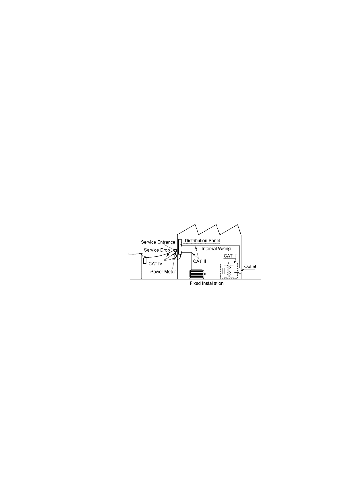
Measurement categories
To ensure safe operation of measurement instruments, IEC 61010 establishes
safety standards for various electrical environments, categorized as CAT II to
CAT IV, and called measurement categories.
CAT II Primary electrical circuits in equipment connected to an AC
electrical outlet by a power cord (portable tools, household
appliances, etc.)
CAT II covers directly measuring electrical outlet receptacles.
CAT III Primary electrical circuits of heavy equipment (fixed installations)
connected directly to the distribution panel, and feeders from the
distribution panel to outlets.
CAT IV The circuit from the service drop to the service entrance, and to
the power meter and primary overcurrent protection device
(distribution panel).
Using a measurement instrument in an environment designated with a
higher-numbered category than that for which the instrument is rated could
result in a severe accident, and must be carefully avoided.
Use of a measurement instrument that is not CAT-rated in CAT II to CAT
IV measurement applications could result in a severe accident, and must be
carefully avoided.
______________________________________________________________________________________________
_____________________________________________________________________________________________
v
Points for Attention During Use
Follow these precautions to ensure safe operation and to obtain the full
benefits of the various functions.
WARNING
CAUTION
Before turning the product on, make sure the source voltage
matches that indicated on the product's power connector.
Connection to an improper supply voltage may damage the product
and present an electrical hazard.
To avoid electrical accidents and to maintain the safety
specifications of this instrument, connect the power cord provided
only to a 3-contact (two-conductor + ground) outlet.
To avoid electric shock, do not remove the instrument's case. The
internal components of the instrument carry high voltages and may
become very hot during operation.
Various connectors are present on the outside of the 3532-50. Never
connect any cable to any of these connectors without first turning off the
power supply and removing the power cord. Moreover, check the
connections carefully in order to avoid any chance of setting up a short
circuit etc..
If anything unusual happens during operation of the unit, turn off the
power switch immediately and contact any HIOKI service facility for help,
advice and service.
This product should be installed and operated between 0 and 40 and
80% RH or less, and less than 2000 m height.
The unit should always be stored in a range of temperature and humidity
from -10
Do not store or use the product where it could be exposed to direct
to 55 , 80% RH or less.
sunlight, high temperature or humidity, or condensation. Under such
conditions, the product may be damaged and insulation may deteriorate
so that it no longer meets specifications.
To avoid damage to the product, protect it from vibration or shock during
transport and handling, and be especially careful to avoid dropping.
Do not use excessive force on the touch panel, and do not use sharp
objects that could damage the touch screen.
Before using the instrument, make sure that the insulation on the probes
is undamaged and that no bare conductors are improperly exposed.
Using the instrument in such conditions could cause an electric shock, so
contact your dealer or Hioki representative for repair.
Ventilation holes for heat radiation are provided on the side panels of the
product. Leave sufficient space around the ventilation holes and install
the product with the holes unobstructed. Installation of the product with
the ventilation holes obstructed may cause a malfunction or fire.
About the guarantee
You should be aware that HIOKI cannot accept any respo nsibility directly or
indirectly if the unit has been incorporated in some other system, or if it is
resold to a third party.
______________________________________________________________________________________________

vi
_____________________________________________________________________________________________
Layout of This Manual
Chapter 1 Product Overview
Describes the product generally, and lists the parts and functions.
Chapter 2 Before Starting Measurement
How to connect the power cord etc., and important precautions before
operation.
Chapter 3 Outline of Operation
Explains the touch panel and basic testing.
Chapter 4 Detailed Description of Functions
Detailed explanation of the functions.
Chapter 5 Detailed Description of Applications
Various testing applications.
Chapter 6 Maintenance, Adjustment, and Disposal
Chapter 7 Specification and Options
Index
______________________________________________________________________________________________

_____________________________________________________________________________________________
1
Chapter 1
1
2
1.1 Product Overview
The HIOKI 3532-50 LCR HiTESTER is an impedance meter which uses a
touch panel as the user interface. This interactive touch panel enables
extremely easy operation. The test frequency can be set from 42 Hz to 5
MHz at high resolution.
The values of a maximum of any four of the fourteen test parameters,
including not only impedance |Z| and phase angle θ, but also L, C, and R
etc., can be simultaneously displayed upon the screen.
Moreover, this widely applicable impedance meter can be set, not only to a
floating voltage setting, but also to a constant voltage setting or a constant
current setting.
Product Overview
3
4
5
6
7
8
9
10
11
12
13
14
A
______________________________________________________________________________________________
1.1 Product Overview

2
_____________________________________________________________________________________________
1.2 Product Features
Wide range of test frequencies
The test frequency can be selected from a wide range - 42 Hz to 5 MHz - at
high resolution (Three-digit resolution for not more than 100 Hz, and fourdigit resolution for not more than 5 MHz). Frequency dependent assessment
of electronic components and materials, etc., is possible.
Constant voltage and constant current testing
Assessment of dependence upon voltage or current is possible.
Outstanding operability
All control operations are initiated via a touch panel on the display. All the
keys currently available for use are shown on the display, and can be
operated interactively.
Simultaneous display of four parameters
Up to four of the test parameters (such as L,C,R, etc.) can be displayed
simultaneously.
Interface
Using a computer, any required parameters can be captured
Changing settings without stopping measurement
Various background settings can be changed without stopping measurement
(when an internal trigger is set).
______________________________________________________________________________________________
1.2 Product Features
_____________________________________________________________________________________________
3
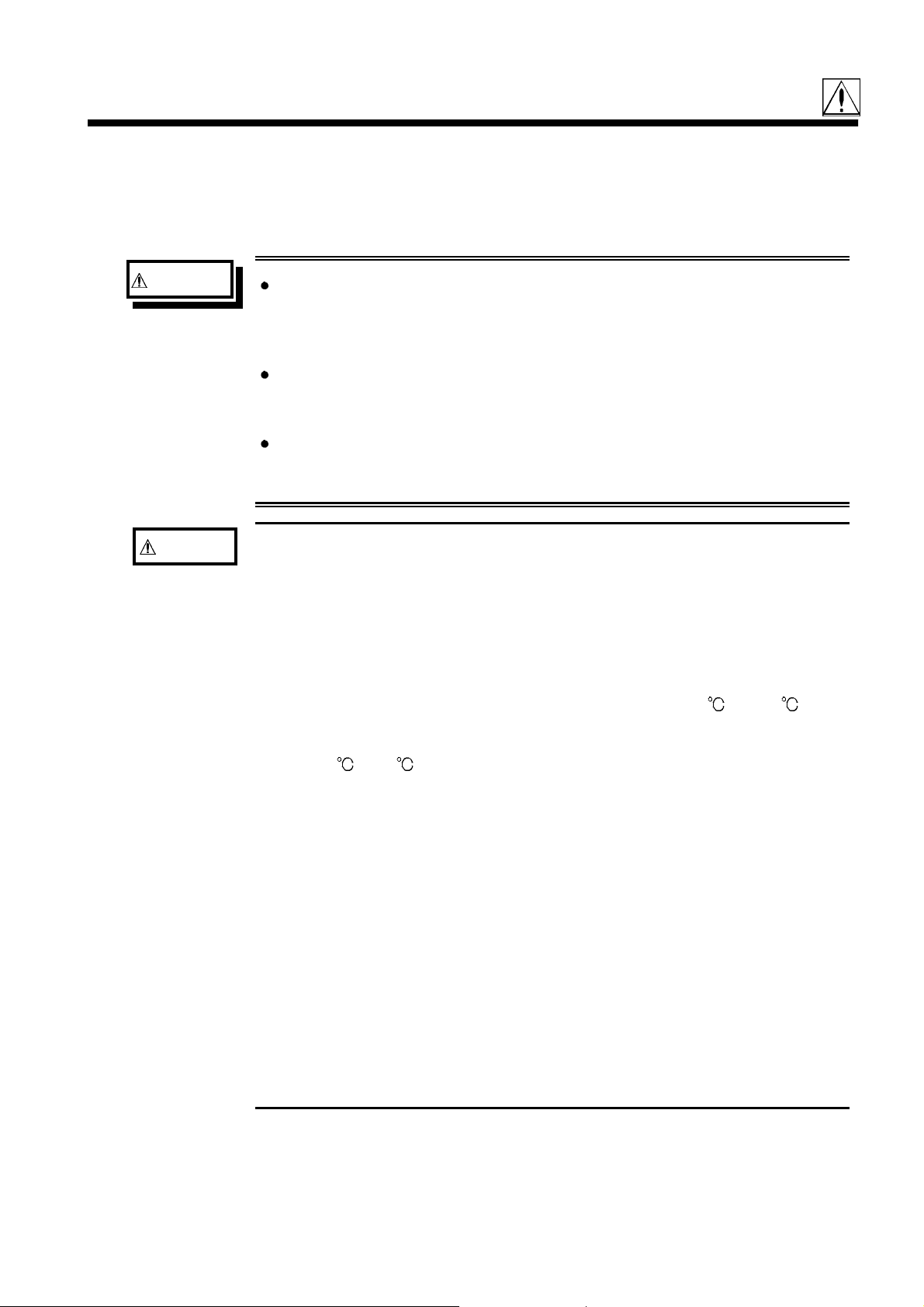
1.3 Names and Functions of Parts
Liquid crystal display
Test terminals
Contrast adjustment knob
Power switch
1
1
2
2
3
3
4
4
5
5
6
6
Front View
Liquid crystal display
This is a 5-inch liquid crystal display fitted with a touch panel. It also
serves to provide input keys.
Power switch
Turns the power for the unit on and off.
Contrast adjustment knob
This knob adjusts the screen contrast. Turning it clockwise decreases the
contrast, and vice versa.
Test terminals
There are five test terminals:
The test signal is supplied to this terminal.
H
CUR
H
POT
Detected voltage low terminal
L
POT
L
CUR
GUARD
These test terminals are designed according to the safety standard;
Pollution Degree 2, Measurement category I.
Detected voltage high terminal
Test current detected terminal
Guard terminal
7
7
8
8
9
9
10
10
11
11
12
12
13
13
14
14
______________________________________________________________________________________________
1.3 Names and Functions of Parts
A
A

4
_____________________________________________________________________________________________
Power input socket
with voltage selector
Optional equipment interface
Key lock switch
EXT I/O connector
Heat sink
Rear View
Power input socket (internally fused type) with voltage selector
Connect the supplied power cord here.
Optional equipment interface
Optional interface boards are connected here.
EXT I/O connector
For input of an external trigger signal and output of comparator results.
Compatible with sequencer connection.
Key lock switch
Puts the touch panel keys into the input-not-accepted state.
______________________________________________________________________________________________
1.3 Names and Functions of Parts
_____________________________________________________________________________________________
5
1
1
2
2
3
3
4
4
5
5
6
6
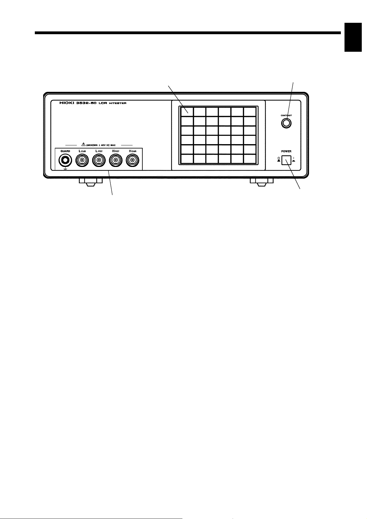
Stand
CAUTION
Right View
Stand
Can be opened to tilt the unit upwards.
Do not apply strong downward pressure with the stand extended.
Damage to the stand will result.
7
7
8
8
9
9
10
10
11
11
12
12
13
13
______________________________________________________________________________________________
1.3 Names and Functions of Parts
14
14
A
A

6
_____________________________________________________________________________________________
Handle
Left View
Handle
Used when carrying the unit.
______________________________________________________________________________________________
1.3 Names and Functions of Parts

_____________________________________________________________________________________________
7
Chapter 2
1
2
Before Starting Measurement
2.1 Connecting the Power Cord
WARNING
When a 3532-50 unit is ordered, the supply voltage is set in the
factory to the value specified, which can be 100 V, 120 V, 220 V, or
240 V.
The maximum rated power (with all options fitted) is 50 VA.
Before turning the product on, make sure the source voltage
matches that indicated on the product's power connector.
Connection to an improper supply voltage may damage the product
and present an electrical hazard.
The power supply voltage for this product is switchable. To avoid
electrical accidents, check that the voltage selector is set correctly for
the supply voltage you are using. (For details, refer to Section 6.2)
3
4
5
6
7
8
9
To avoid electrical accidents and to maintain the safety
specifications of this instrument, connect the power cord provided
only to a 3-contact (two-conductor + ground) outlet.
The power cord is connected according to the following
procedure.
1. Check that the main power switch of the unit is off.
2. Check that the power supply voltage is correct, and
connect the proper end of the power cord to the power
input socket (with voltage selector) at the rear of the unit.
3. Plug the other end of the power cord into the power
supply socket.
Grounding
Use the grounding type (three-wire) power cord supplied.
The unit will be grounded automatically.
10
11
12
13
14
A
______________________________________________________________________________________________
2.1 Connecting the Power Cord

8
_____________________________________________________________________________________________
2.2 Connecting the Test Leads
The 3532-50 has five test terminals: H
is supplied); H
terminal (detected voltage high terminal); L
POT
(detected voltage low terminal); L
terminal), and GUARD terminal (connected to the chassis of the unit).
2.2.1 Establishing the Connections
CAUTION
Using a low frequency to measure capacitors with a particular polarity (for
example, electrolytic capacitors) results in a reverse bias being applied.
In some cases this could damage or destroy the capacitor, and therefore
a DC bias should always be applied while making the measurements.
Also be sure that the positive terminal of the capacitor is connected to
the Hcur terminal on this unit.
When measuring capacitors with a particular polarity (for example,
electrolytic capacitors), always apply a DC bias.
If the DC bias is not applied, a reverse bias may be applied, damaging or
destroying the capacitor.
terminal (to which the test signal
CUR
terminal (test current detected
CUR
POT
terminal
If using a test lead set supplied by HIOKI, connect the red leads to the H
terminal and to the H
terminal and to the L
Black
terminal, and connect the black leads to the L
POT
terminal.
POT
Red
CUR
The unit is designed and adjusted for 75 Ω coaxial cable test leads. It is
best to use HIOKI test leads.
CUR
______________________________________________________________________________________________
2.2 Connecting the Test Leads

_____________________________________________________________________________________________
9
NOTE
The connections to the article to be tested are as shown in the following
figure.
Test fixture
No test cables are included with the 3532-50 unit. They must be
purchased separately. (For details, refer to Section 7.4, "Options")
If all four terminals are left floating, the numbers which appear on the
display are completely meaningless.
1
2
3
4
5
6
7
8
9
10
11
12
13
______________________________________________________________________________________________
2.2 Connecting the Test Leads
14
A

10
_____________________________________________________________________________________________
2.3 Turning the Power On and Off
How to turn the power on
1. Turn on the power switch on the front panel. The Initial screen will be
displayed on the liquid crystal display.
Off
On
The test conditions will start off the same as they were when last the power
was turned off.
2. Adjust the contrast knob so as to make the display as easy to see as possible.
Darker
Brighter
3. Wait for 60 minutes after turning on the power before starting testing, so as
to allow the unit to warm up fully.
How to turn the power off
Turn off the power switch on the front panel. The test conditions will be
preserved.
NOTE
Even if the power supply is interrupted because of a power failure or the
like, the test conditions (settings) will not be lost; when the power is turned
on again, the unit will return to its state just before the interruption.
______________________________________________________________________________________________
2.3 Turning the Power On and Off

_____________________________________________________________________________________________
11
Chapter 3
1
2
3.1 About the Touch Panel
CAUTION
Do not use excessive force on the touch panel, and do not use sharp
objects that could damage the touch screen.
The 3532-50 uses a touch panel for setting and changing all of the test
conditions. Simply by touching the LCD screen at certain areas - termed soft
keys - which appear in reverse video, the items associated with these soft
keys, and numerical values, can be selected.
In this manual, lightly touching a soft key area on the screen is termed
"pressing" a key.
Outline of Operation
3
4
5
6
7
8
9
Initial Screen
10
11
12
13
14
A
______________________________________________________________________________________________
3.1 About the Touch Panel

12
_____________________________________________________________________________________________
3.2 About the Screen
(1) The Initial screen
When the power is first turned on, the basic screen for controlling the 3532-
50 immediately appears, called the "Initial screen". A maximum of four of
the test parameters (L, C, R, etc.) can be set for display, and all of the test
conditions can be checked, on this Initial screen.
The Menu screen can be displayed by pressing the key.
The Parameter setting screen can be displayed by pressing a parameter key.
Parameter
keys
Monitor
display
For details, refer to Section 4.1.1, "The Initial Screen."
(2) The Menu screen
The Menu screen is used for selecting whichever of the test conditions you
want to change. Pressing one of the keys on this screen changes over the
display to the appropriate test condition setting screen.
To change any one of the test
conditions (frequency, controlled
level, etc.), press the corresponding
key on this menu.
Menu key
Initial Screen
Menu
Screen
For details, refer to Section 4.1.2, "The Menu Screen and Application Menu
Screen"
______________________________________________________________________________________________
3.2 About the Screen

_____________________________________________________________________________________________
13
(3) The Parameter setting screen
Pressing a parameter key on the Initial screen causes the Parameter setting
screen to be displayed, using which the test parameters to be displayed (up
to a maximum of four) are selected.
By pressing a key for any test parameter, that parameter is set to be
displayed, and the unit automatically returns to displaying the Initial screen
again.
1
2
3
4
Test
parameters
5
6
(4) The Test condition setting screen
This screen is for changing a test condition (for example, the test frequency).
When you have finished setting the test condition, press the key, and the
unit will return to displaying the Initial screen again.
The inactive keys
(which cannot currently
be operated) appear as white
rectangles with black character
legends, i.e. in non-reversed
video.
7
Parameter Setting Screen
8
9
10
11
12
13
14
Test Condition Setting Screen
(Test frequency setti ng screen)
A
______________________________________________________________________________________________
3.2 About the Screen

14
_____________________________________________________________________________________________
3.2.1 Control Screen Sequence
The basic flow for the change of screens as control operation is performed is
as follows.
The measurement values can be checked in real time on all of the screens.
The measured values of any of the test parameters
can be displayed for checking (up to a maximum
of four) and all of the test conditions can be
checked on the Initial screen.
To make a change to the test conditions:
Press the soft key, and the Menu screen will
be displayed.
Initial Screen
Select the test condition to alter on the Menu
screen (for example, when changing the test
frequency).
Menu Screen
Setting Screen
Press the soft key, and the Frequency setting
screen will be displayed.
Set or change that test condition on the appropriate
Test condition setting screen.
When the test condition setting is complete,
press the soft key, and the display will return
to displaying the Initial screen.
Initial Screen
______________________________________________________________________________________________
3.2 About the Screen

_____________________________________________________________________________________________
15
3.3 Basic Measurement
1
In order to explain the basic operation of the 3532-50 unit, as an example,
the procedure will be shown for establishing the following settings:
Example
NOTE
Sample to be tested
Capacitor 0.1 μF
Test conditions
Test frequency 100 kHz
Constant voltage level 0.4 V
Open circuit compensation setup ALL compensation
Short circuit compensation setup ALL compensation
Parameters to be displayed
Capacitance Cs, Loss coefficient D
The trigger is internal. The 3532-50 unit, when it is dispatched from the
factory, is in the internal trigger state.
3.3.1 Basic Flow up to Testing of the Sample
The basic flow up to starting testing of the sample is as shown in the
following chart in correspondence to the applicable reference sections:
2
3
4
5
6
7
8
Step Reference sections
Select the test parameters
to be displayed
Set the test frequency
Set the voltage level
Open circuit compensation
Short circuit compensation
Start testing
3.3.2, "Setting the Test Parameters to be Displayed
(Cs, D)"
3.3.3, "Setting the Test Frequency"
3.3.4, "Setting the Constant Voltage Level"
3.3.5, "Setting Open Circuit Compensation"
3.3.6, "Setting Short Circuit Compensation"
9
10
11
12
13
14
______________________________________________________________________________________________
3.3 Basic Measurement
A
16
_____________________________________________________________________________________________
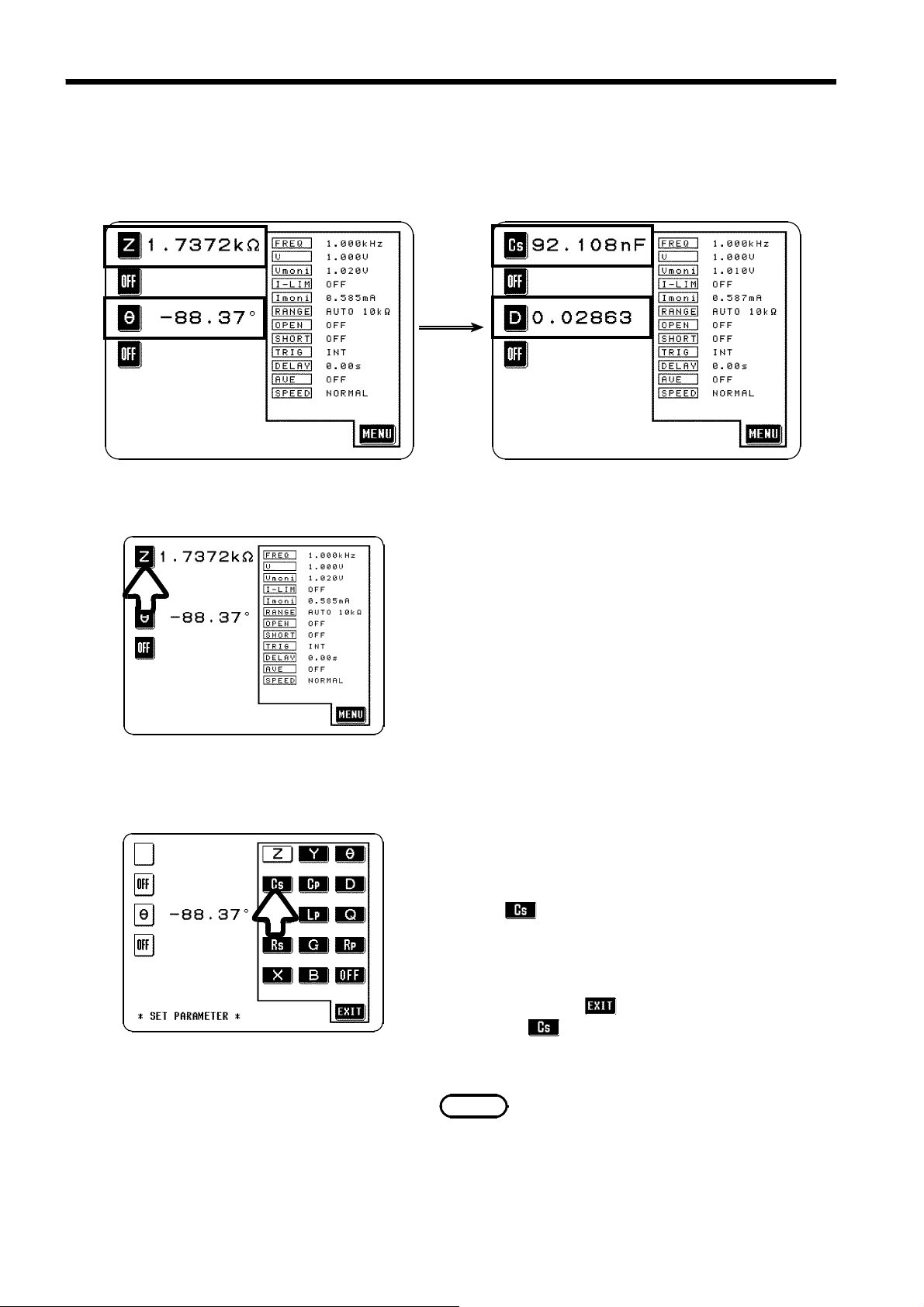
3.3.2 Setting the Test Parameters to be Displayed (Cs, D)
Here the first (i.e., the uppermost) parameter key will be set to capacitance
Cs, and the third parameter key will be set to loss
coefficient D.
Before Setting
Setting procedure
Initial Screen
After Setting
1. In order to change the first parameter displayed
on the Initial screen, press the first (uppermost)
parameter key.
2. The Parameter setting screen is displayed. (The
test parameter (currently Z) to which the pressed
parameter key currently corresponds is shown in
black characters on a white ground, i.e. in nonreversed video).
Press on this screen, and the display will
automatically return to displaying the Initial
screen, with capacitance Cs being displayed as
the first parameter.
If you press the key on this screen without
Parameter Setting Screen
pressing
the display just returns to displaying the Initial
no new setting is performed, and
,
screen.
NOTE
Any of the test parameters (Z,L,C,R, etc.) (up
to a maximum of four) can be set to correspond
to any of the four parameter keys.
______________________________________________________________________________________________
3.3 Basic Measurement
 Loading...