

Hioki 3504-50, 3504-60 Instruction Manual
3504-40
3504-50
3504-60
C HiTESTER
Instruction Manual
Sept. 2018 Revised edition 4
3504D981-04 18-09H
EN


Contents
Introduction.................................................................................1
Verifying Package Contents .......................................................1
Safety Information ......................................................................2
Operating Precautions................................................................4
i
Contents
1
2
Chapter 1
Overview ___________________________________ 7
1.1 Product Overview .........................................................7
1.2 Features .......................................................................7
1.3 Entire Workflow ............................................................8
1.4 Names and Functions of Parts ...................................10
Chapter 2
Measurement Preparations___________________ 17
2.1 Preparation Flowchart ................................................17
2.2 Checking the Power Voltage...................................... 18
2.3 Connecting the Power Cord ....................................... 19
2.4 Connecting the Probes and Fixtures.......................... 20
2.5 Turning the Power On and Off ...................................21
3
4
4
5
5
6
6
7
7
8
Chapter 3
Basic Measurement _________________________ 23
3.1 Pre-Operation Inspection ...........................................23
3.2 Measurement Example ..............................................24
3.3 Setting the Measurement Conditions .........................26
3.3.1 Measurement Mode ......................................................26
3.3.2 Measurement Frequency ..............................................26
3.3.3 Measurement Signal Level ............................................27
3.3.4 Measurement Speed .....................................................28
3.3.5 Equivalent Circuit Mode ................................................29
3.3.6 Measurement Range .....................................................31
3.3.7 Trigger Signal ................................................................36
3504D981-04
8
9
9
10
10
Appendix
App
Index
Index

ii
Contents
Chapter 4
Compensatefor errors _______________________ 37
4.1 Open Circuit Compensation and Short Circuit
Compensation ........................................................... 37
4.2 Load Compensation .................................................. 47
4.3 Offset Compensation ................................................. 54
4.4 Self Calibration .......................................................... 58
Chapter 5
Judging measurement results ________________61
5.1 Comparator Function ................................................. 61
5.2 BIN Measurement Function
(Model 3504-50, 3504-60 only) ................................. 75
Chapter 6
Application Functions _______________________ 91
6.1 Setting the Average Function .................................... 91
6.2 Trigger Delay Setting ................................................. 93
6.3 Evaluate Contact Check Function ............................. 95
6.3.1 Setting the Low C Reject Function ............................... 96
6.3.2 Measurement Level Monitoring Function Settings ........ 98
6.3.3 Contact Check Function Settings
(Model 3504-60 only) .................................................. 100
6.4 Setting the Display ON/ OFF ................................... 103
6.5 Trigger Synchronous Output Function ..................... 104
6.6 Disable Key Control (Keylock Function) .................. 106
6.7 Save the Measurement Conditions
(Panel Save Function) ............................................. 107
6.8 Load the Measurement Conditions
(Panel Load Function) ............................................. 108
6.9 Setting Beep Tones ................................................. 112
6.9.1 Setting the Beep Tone for Judgment Results of
Comparator and BIN ................................................... 112
6.9.2 Setting the Beep Tone for Key Operations ................. 114
6.10 Switching the displayed item (SUB display) ............ 115
6.11 Performing a System Reset ..................................... 117
6.12 Printing Function ...................................................... 118
6.12.1 Preparation Prior to Connecting the Printer ................ 118
6.12.2 Connection Procedure ................................................ 121

6.12.3 Printing ........................................................................122
iii
Contents
Chapter 7
EXT I/O __________________________________ 123
7.1 About the EXT I/O Connector .................................. 123
7.2 Circuit Configuration and Connections of the EXT I/O
Connector .................................................................125
7.3 About Input and Output Signals ...............................126
7.4 About Measurement Times ......................................128
Chapter 8
Controlling the Unit from a PC _______________ 131
8.1 Outline and Features ................................................131
8.2 Specifications ...........................................................132
8.2.1 RS-232C Specifications ..............................................132
8.2.2 GP-IB Specifications
(Only for Models 3504-50, 3504-60) 133
8.3 Connection and Setting Procedures ........................134
8.3.1 Connecting the RS-232C Cable / GP-IB Cable ...........134
8.3.2 Setting the Interface Communication Conditions ........136
8.4 Remote Function ......................................................139
1
2
3
4
5
6
7
8.5 Communication Procedure .......................................140
8.6 Things to Know before Beginning
Communication 141
8.6.1 About Message Formats .............................................141
8.6.2 About the Output Queue and Input Buffer ...................146
8.6.3 About the Status Byte Register ...................................147
8.6.4 About Event Registers ................................................149
8.7 Message List ............................................................154
8.8 Ability to Use Commands by State ...........................167
8.8.1 Common Commands ..................................................167
8.8.2 Unique Commands ......................................................167
8.9 Message Reference .................................................172
8.9.1 Common Commands ..................................................173
8.9.2 Unique Commands ......................................................178
8.9.3 Response Format of Queries for Returning Values ....243
8.10 Initialized Items ........................................................245
8.11 Creating Programs ...................................................246
8.11.1 Creation Procedure .....................................................246
8.11.2 Sample Programs ........................................................248
8
9
10
Appendix
Index

iv
Contents
8.12 Troubleshooting the Interface .................................. 250
8.13 Device Document Requirements
(Only for Models 3504-50, 3504-60)........................ 252
Chapter 9
Specifications _____________________________ 255
9.1 Basic Specifications ................................................. 255
9.2 Accuracy .................................................................. 259
9.3 Measurement Parameters and
Arithmetic Expressions 261
Chapter 10
Maintenance and Service ___________________263
10.1 Inspection, Repair, and Cleaning ............................ 263
10.2 Replacing the Power Fuse ...................................... 265
10.3 Discarding the Unit .................................................. 266
Appendix _________________________________ A1
Appendix 1 Countermeasures Against
Incorporation of External Noise........................ A1
Appendix 1.1Countermeasures Against Incorporation of
Noise from the Power Line .............................................1
Appendix 1.2Countermeasures Against Incorporation of
Noise from the Input Line (Types of Probe) .................... 2
Appendix 2 Measurement of High Impedance ComponentsA3
Appendix 3 Measurement of In-circuit Components ...........A4
Appendix 4 Mounting the Unit in a Rack ............................. A5
Appendix 5 External View ...................................................A7
Appendix 6 Options ............................................................. A8
Appendix 7 Initial Settings Table ....................................... A11
Index ______________________________________ i
Introduction
3504-40 C HiTester
3504-50 C HiTester
3504-60 C HiTester
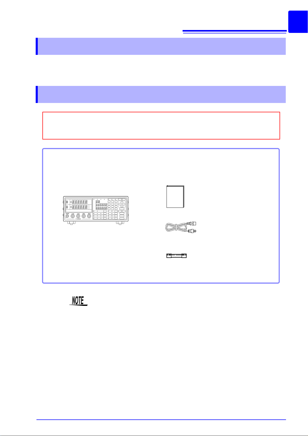
Confirm that these contents are provided.
Accessories
Instruction Manual................................... 1
Power cord.............................................. 1
Spare fuse for power supply
(according to voltage specification)........ 1
100 V, 120 V setting: 250 VF 1.0 AL5 x 20 mm dia
220 V, 240 V setting: 250 VF 0.5 AL5 x 20 mm dia
When you receive the unit, inspect it carefully to ensure that no damage occurred during shipping.
In particular, check the accessories, panel switches, and connectors. If damage is evident, or if it
fails to operate according to the specifications, contact your dealer or Hioki representative.
This unit
Thank you for purchasing the HIOKI “Model 3504-40, 3504-50, 3504-60 C
HiTester.” To obtain maximum performance from the unit, please read this
manual first, and keep it handy for future reference.
Verifying Package Contents
1
Probes, fixture are not supplied with the unit as standard equipment. You
Options
should order them separately, according to requirements.
Appendix 6 "Options" (p. A8)
2
Safety Information
This instrument is designed to comply with IEC 61010 Safety Standards, and has been thoroughly tested for afety prior to shipment.
However, mishandling during use could result in injury or death, as
well as damage to the instrument. Using the instrument in a way not
described in this manual may negate the provided safety features. Be
certain that you understand the instructions and precautions in the
manual before use. We disclaim a ny re sponsibility for a ccidents or
injuries not resulting directly from instrument defects.
This manual contains information and warnings essential for safe operation of
the unit and for maintaining it in safe operating condition. Before using it, be
sure to carefully read the following safety precautions.
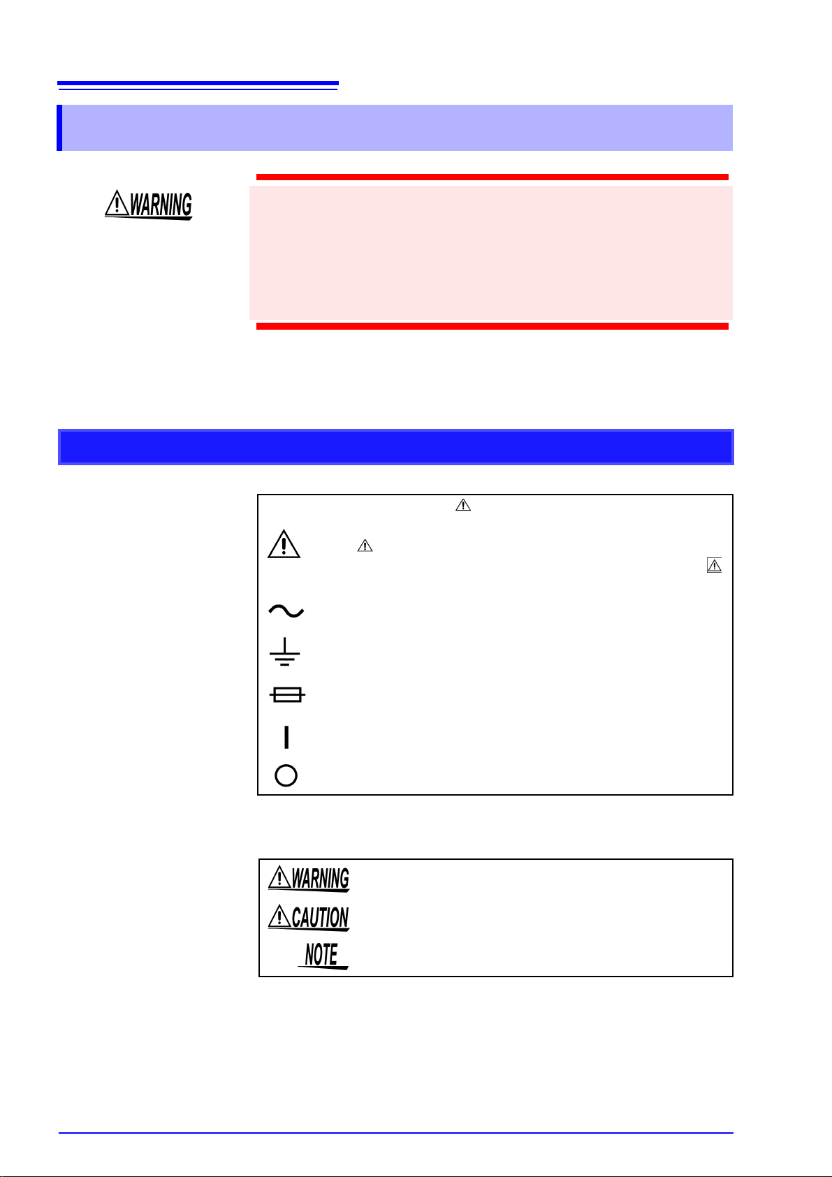
Safety Symbols
In the manual, the symbol indicates particularly important
information that the user should read before using the unit.
The symbol printed on the unit indicates that the user should
refer to a corresponding topic in the manual (marked with the
symbol) before using the relevant function.
Indicates AC (Alternating Current).
Indicates a grounding terminal.
Indicates a fuse.
Indicates the ON side of the power switch.
Indicates the OFF side of the power switch.
The following symbols in this manual indicate the relative importance of cautions and warnings.
Indicates that incorrect operation presents a significant hazard that could result in serious injury or death to the user.
Indicates that incorrect operation presents a possibility of
injury to the user or damage to the unit.
Indicates advisory items related to performance or correct
operation of the unit.
Other Symbols
3
Indicates a prohibited action.
See Indicates the location of reference information.
Indicates quick references for operation and remedies for
troubleshooting.
Accuracy
We define measurement tolerances in terms of rdg. (reading) and dgt. (digit) values, with the following meanings:
rdg.
(reading or displayed value)
dgt. (resolution) The smallest displayable unit on a digital
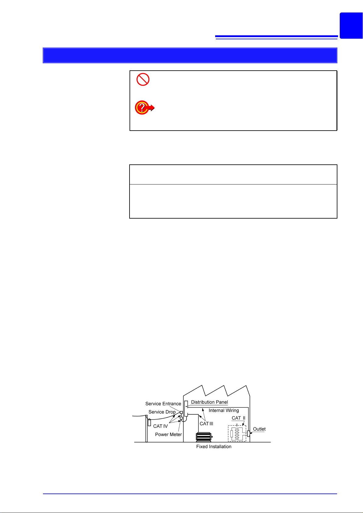
Measurement categories
To ensure safe operation of measurement instruments, IEC 61010 establishes safety standards for various electrical environments, categorized as
CAT II to CAT IV, and called measurement categories.
CAT II: Primary electrical circuits in equipment connected to an AC electrical
CAT III: Primary electrical circuits of heavy equipment (fixed installations) con-
CAT IV:The circuit from the service drop to the service entrance, and to the
Using a measurement instrument in an environment designated with a
higher-numbered category than that for which the instrument is rated could
result in a severe accident, and must be carefully avoided.
Use of a measurement instrument that is not CAT-rated in CAT II to CAT IV
measurement applications could result in a severe accident, and must be
carefully avoided.
*
outlet by a power cord (portable tools, household appliances, etc.)
CAT II covers directly measuring electrical outlet receptacles.
nected directly to the distribution panel, and feeders from the distribution panel to outlets.
power meter and primary overcurrent protection device (distribution
panel).
Indicates that descriptive information is provided below.
The value currently being measured and
indicated on the measuring unit.
measuring unit/ device/ product, i.e., the
input value that causes the digital display
to show a "1" as the least-significant digit.
4
Operating Precautions
Follow these precautions to ensure safe operation and to obtain the full benefits of the various functions.
Preliminary Checks
Before using the unit the first time, verify that it operates normally to ensure
that the no damage occurred during storage or shipping. If you find any damage, contact your dealer or Hioki representative.
Before using the unit, make sure that the insulation on the probes and
cables is undamaged and that no bare conductors are improperly
exposed. Using the unit in such conditions could cause an electric
shock, so contact your dealer or Hioki representative for replacements.
Unit Installation
Operating Temperature and Humidity: 0 to 40°C), 80%RH or less, no con-
densation
Storage Temperature and Humidity: -10 to 55
sation
Accuracy-guaranteed temperature and humidity ranges: 23
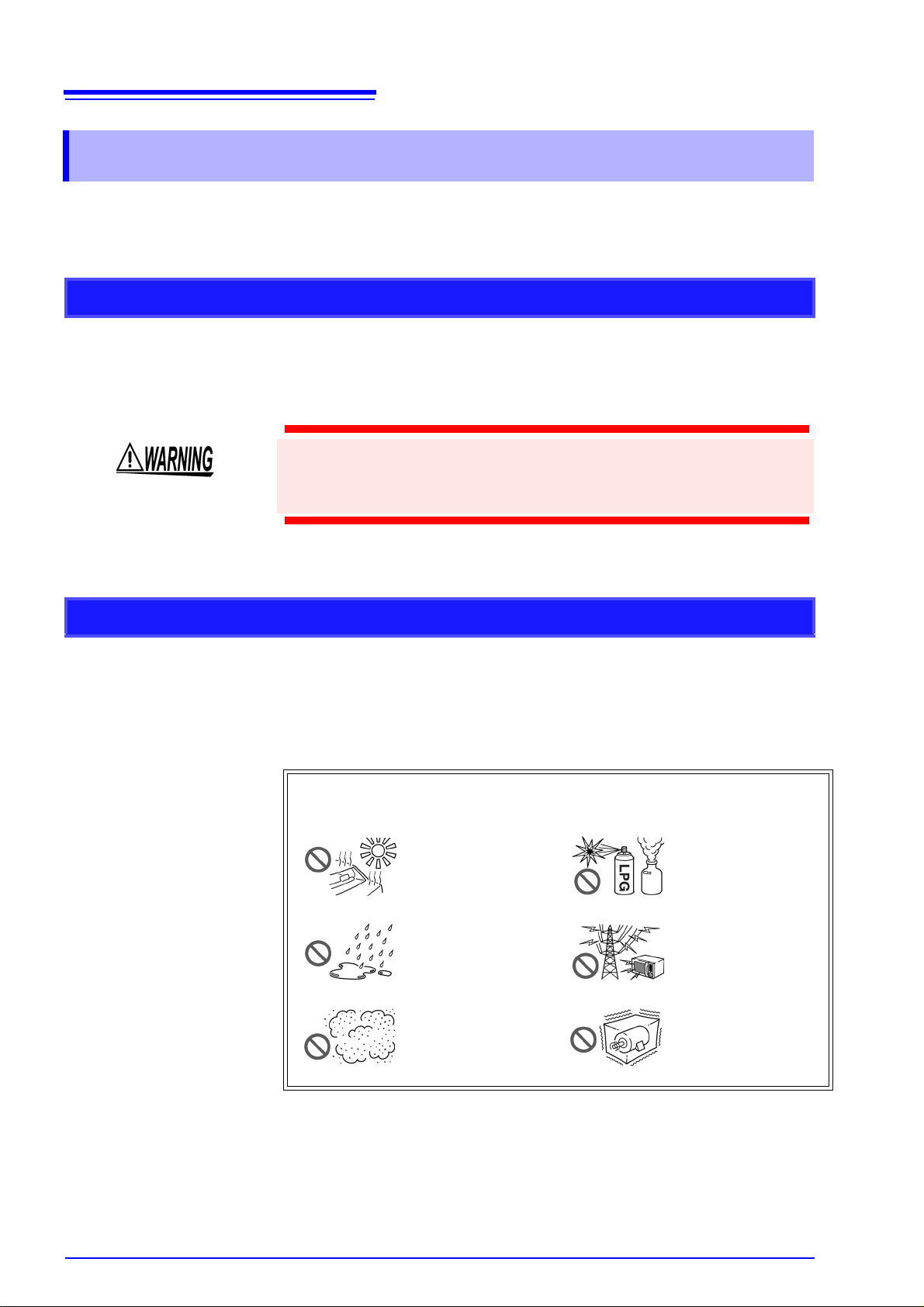
Avoid the following locations that could cause an accident or damage
to the unit.
Exposed to direct sunlight
Exposed to high temperature
Exposed to liquids
Exposed to high humidity or condensation
Exposed to high levels of particulate dust
°C, 80%RH or less, no undone-
±5°C, 80%RH
In the presence of corrosive or explosive
gases
Exposed to strong
electromagnetic fields
Near electromagnetic
radiators
Subject to vibration
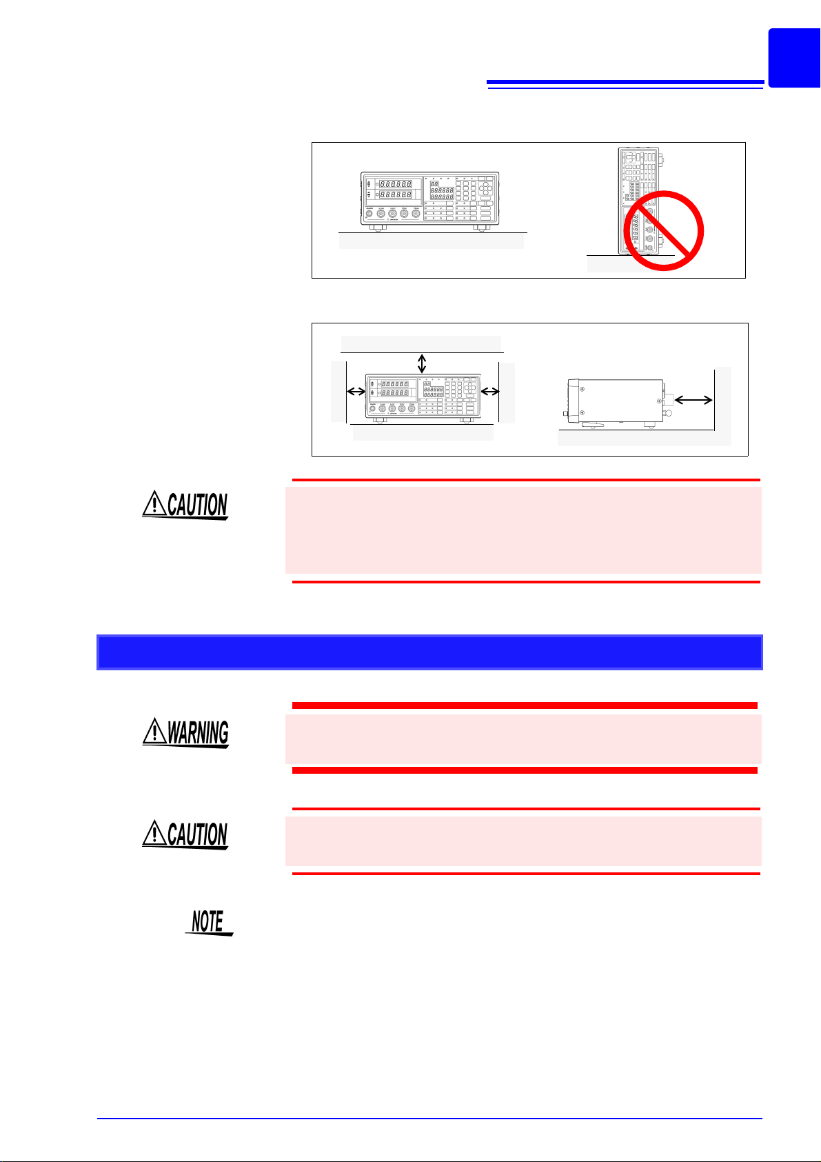
Installing
OK
10 cm or more
5 cm or more
5
• Do not install the unit with any side except the bottom facing down.
• Vents must not be obstructed.
Handling this device
• To avoid damage to the unit, protect it from physical shock when transporting and handling. Be especially careful to avoid physical shock from dropping.
• Do not apply heavy downward pressure with the stand extended. The stand
could be damaged.
Never modify the unit. Only Hioki service engineers should disassemble or repair the unit. Failure to observe these precautions may result in
fire, electric shock, or injury.
If anything unusual happens during operation of the unit, turn off the
power switch immediately and contact any HIOKI service facility for
help, advice and service.
This instrument may cause interference if used in residential areas. Such
use must be avoided unless the user takes special measures to reduce
electromagnetic emissions to prevent interference to the reception of radio
and television broadcasts.

6
Before connection and powering on
• Before turning the unit on, make sure the supply voltage matches
that indicated on the its power connector. Connection to an improper
supply voltage may damage the unit and present an electrical hazard.
• The power supply voltage for this unit is switchable. To avoid electrical accidents, check that the voltage selector is set correctly for the
supply voltage you are using.
See
Setting Procedure for the Power Voltage : 2.2 "Checking the Power Voltage"
(p. 18)
• To avoid electrical accidents and to maintain the safety specifications
of this unit, connect the power cord provided only to a 3-contact (twoconductor + ground) outlet.
See
Connection Procedure : 2.3 "Connecting the Power Cord" (p. 19)
• To avoid shock and short circuits, turn off all power before connecting probes.
About the guarantee
Shipping precautions
Check the connections carefully in order to avoid any chance of setting
up a short-circuit etc.
You should be aware that HIOKI cannot accept any responsibility directly or
indirectly if the unit has been incorporated in some other system, or if it is
resold to a third party.
Use the original packing materials when transporting the unit, if possible.

1.1 Product Overview
Overview Chapter 1
1.1 Product Overview
The HIOKI Model 3504-40, 3504-50 and 3504-60 C HiTesters are capacitance
meters employing 120 Hz and 1 kHz frequencies to measure large-value multilayer ceramic capacitors with constant voltage at high speed and high accuracy.
Primary applications include pass-fail judgment and ranking of capacitors on
tape machines and sorters.
1.2 Features
Capacitance-specific units
7
1
These capacitance meters use 120 Hz and 1 kHz measurement frequencies.
High-speed measurement
The Model 3504-40, 3504-50 and 3504-60 are capable of high-speed measurement: 2 ms at measurement frequency 1 kHz, and 10 ms at 120 Hz.
Constant-voltage measurements
Provides constant-voltage measurement capability.
With 1 kHz selected 1 V: to 70 F 500 mV, 100 mV (Model 3504-60 only): to 170 F
With 120 Hz selected1 V: to 0.7 mF 500 mV, 100 mV (Model 3504-60 only): to 1.45 mF
Bin sorting function (Model 3504-50, 3504-60 only) (p. 75)
Capacitors are easily ranked according to C (Capacitance*1) measurement values into as many as 14 classifications.
Comparator function (p. 61)
Easily perform pass-fail judgment of components according to measurements of
both C and D (Dissipation Factor*2).
LED display
Provides superior visibility.
Equipped with standard data transfer interfaces (p. 131)
The Model 3504-40, 3504-50 and 3504-60 offers external I/O for sequencing, a
standard RS-232C interface, and a standard GP-IB interface (
3504-60 only
).
Model 3504-50,
9
Measurement value memory (p. 232)
Up to 32,000 measurement values can be stored in memory.
Trigger-synchronous measurement capability (p. 104)
The measurement signal can be input to the sample in sync with a trigger.
Contact check function (p. 100)
You can check connection problems between the measurement terminal and the
object to be measured.
*1. Capability to store electric charge.*2. An indicator of capacitor losses.
8
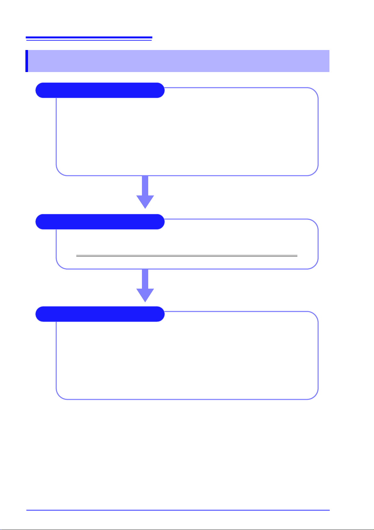
See 3.1 "Pre-Operation Inspection" (p. 23)
Be sure to perform pre-operation inspection prior to measurement.
Check the power voltage.
Connect the power cord.
Connect the probes or fixture (option) to the measurement terminals.
Turn the power on.
Connect the sample.
Prepare the unit, fixture, and sample.
Connect the fixture to the measurement terminals.
Set the measurement conditions.
Connect the sample to the fixture.
Check the measurement results.
Measurement Preparations
1.
2.
3.
4.
5.
1.
2.
3.
4.
5.
See Chapter 2 "Measurement Preparations" (p. 17)
Basic Measurement
See 3.2 "Measurement Example" (p. 24)
Pre-Operation Inspection
1.3 Entire Workflow
1.3 Entire Workflow
Application Functions
9
1.3 Entire Workflow
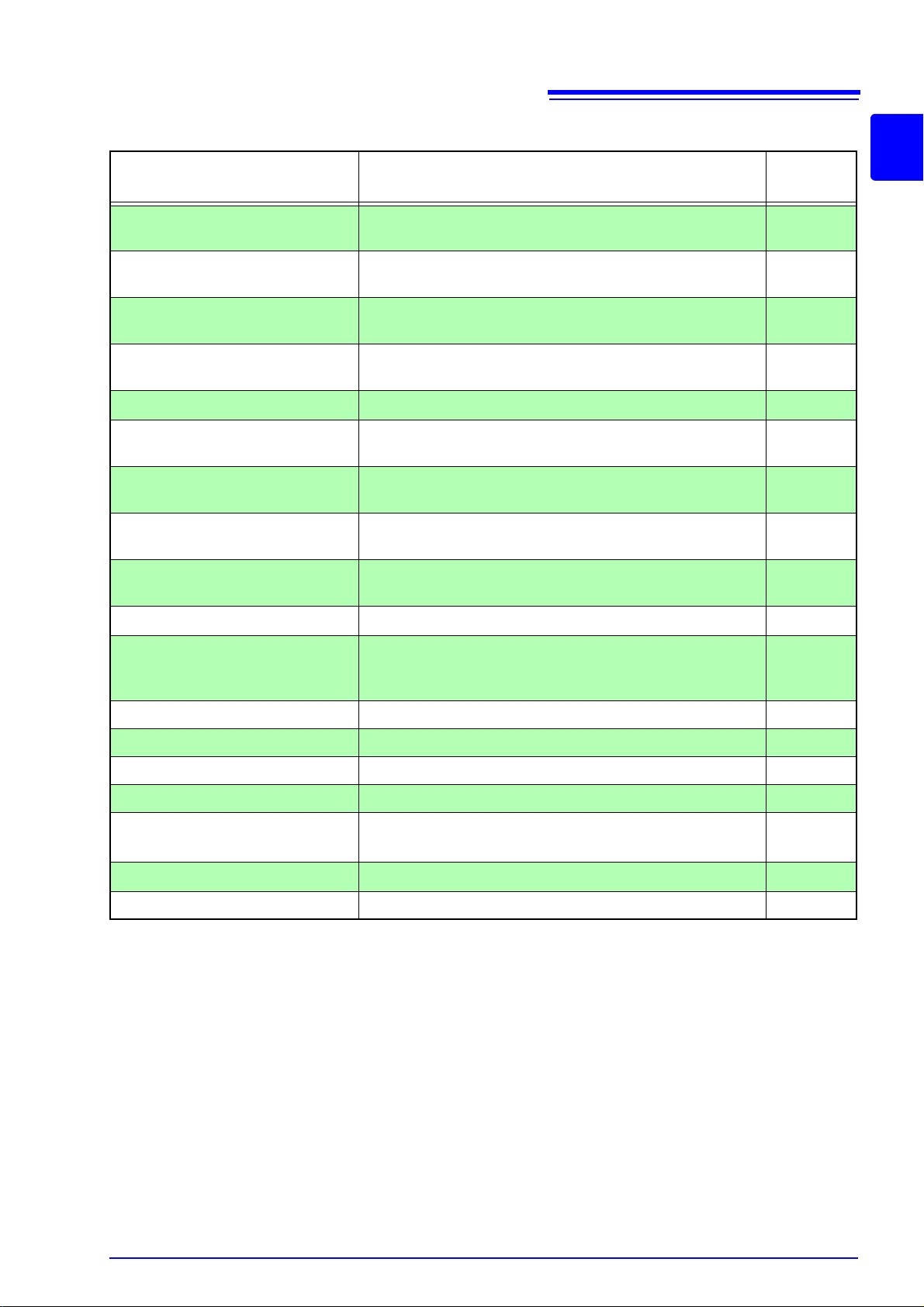
Function Description
Open and Short circuit
compensation
Load compensation Allows interchangeability between measuring instruments
Offset compensation Allows interchangeability between measuring instruments
Comparator measurement
function
Self calibration Reduces measurement value drift. (p. 58)
BIN measurement function Set variations of the upper limit and lower limit values and
Average function Reduces fluctuation of the measurement value by perform-
Trigger delay Provides a reliable measurement value even when taking
Contact check function Discerns whether or not the contact pin and sample are
Eliminates measurement errors due to residual impedance.
by measuring a known sample.
by subtracting the set value from the measurement value.
Set the upper limit and lower limit values and judge whether samples pass or fail.
rank samples accordingly.
ing an averaging process of the measurement values.
a measurement immediately after connecting to a sample.
connected.
Reference
Section
(p. 37)
(p. 47)
(p. 54)
(p. 61)
(p. 75)
(p. 91)
(p. 93)
(p. 95)
1
Display
Trigger synchronous output
function
Key lock function Disable key operations. (p. 106)
Communication function Control the unit from a PC. (p. 131)
Panel save function Save measurement conditions. (p. 107)
Panel load function Load saved measurement conditions (p. 108)
Beep tone
System reset
Printing function Print measurement values. (p. 118)
Turns the LED display ON/ OFF.
Apply the measurement signal only during measurement to
reduce the generation of heat in the sample and decrease
electrode wear.
Turns ON/ OFF the beep tone for judgment results and key
operations.
Resets device settings.
(p. 103)
(p. 104)
(p. 112)
(p. 117)
Application Measurement
• Measurement using EXT I/O
See
7.1 "About the EXT I/O Connector" (p. 123)
• Countermeasures Against Incorporation of External Noise
See
Appendix 1 "Countermeasures Against Incorporation of External Noise" (p. A1)
• Measurement of high impedance components
See
• Measurement of components in circuit networks
Appendix 2 "Measurement of High Impedance Components" (p. A3)
See
Appendix 3 "Measurement of In-circuit Components" (p. A4)
9
10
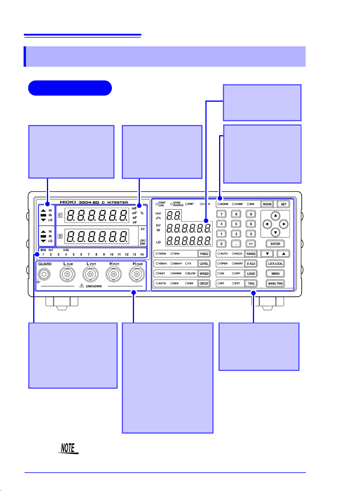
Front
MAIN Display
Displays the measurement
values of C and D.
Displays the MENU items.
Comparator Evaluation
Result Display
Displays evaluation results in
Comparator Mode.
See
5.1 "Comparator Function"
(p. 61)
Operating Panel
Use to set measurement
conditions and to make other
settings
See
(p. 11)
Measurement Terminals
There are five measurement terminals:
H
CUR
Measurement-signal
input terminal
H
POT
Detected voltage high
terminal
L
POT
Detected voltage low
terminal
L
CUR
Measurement current
detected terminal
GUARD Guard terminal
See
2.4 "Connecting the Probes
and Fixtures" (p. 20)
Setting Condition
Display
Displays current measurement conditions, presettings, and other information.
*BIN (Model 3504-50,
3504-60 only)
SUB Display
Displays the limit values of
BIN (Model 3504-50, 350460 only) and comparator.
BIN Judgment Result
Display (Model 3504-50,
3504-60 only)
Displays judgment results in
BIN mode.
See
5.2 "BIN Measurement
Function (Model 3504-50,
3504-60 only)" (p. 75)
1.4 Names and Functions of Parts
1.4 Names and Functions of Parts
The “CONT CHK” and the 100 mV of “LEVEL” in the SUB display portion will
only show 3504-60.
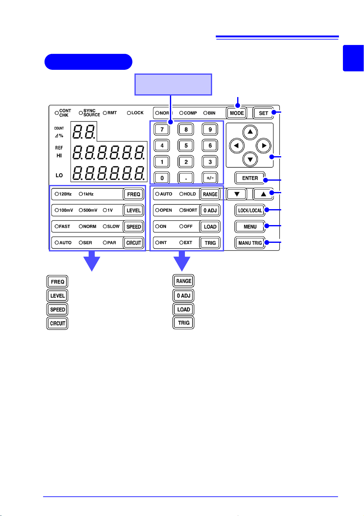
Operating Panel
Keypad
Used to enter numeric values.
Measurement mode
setting(p. 26)
Comparator measurement function
(p. 61)
BIN measurement
function (p. 75)
Arrow keys
Used to change settings and move to
menu items or digits.
Enter
Measurement range
setting
(p. 31)
Lock/ Local
(p. 106)
Menu
Manual trigger
(p. 36)
Measurement frequency setting
(p. 26)
Measurement signal level setting
(p. 27)
Measurement speed setting
(p. 28)
Equivalent circuit mode
(p. 29)
Equivalent circuit mode
(p. 29)
Measurement range setting
(p. 31)
Open (short) circuit compensation
(p. 37)
Load compensation setting
(p. 47)
Trigger mode setting
(p. 36)
11
1.4 Names and Functions of Parts
1
9
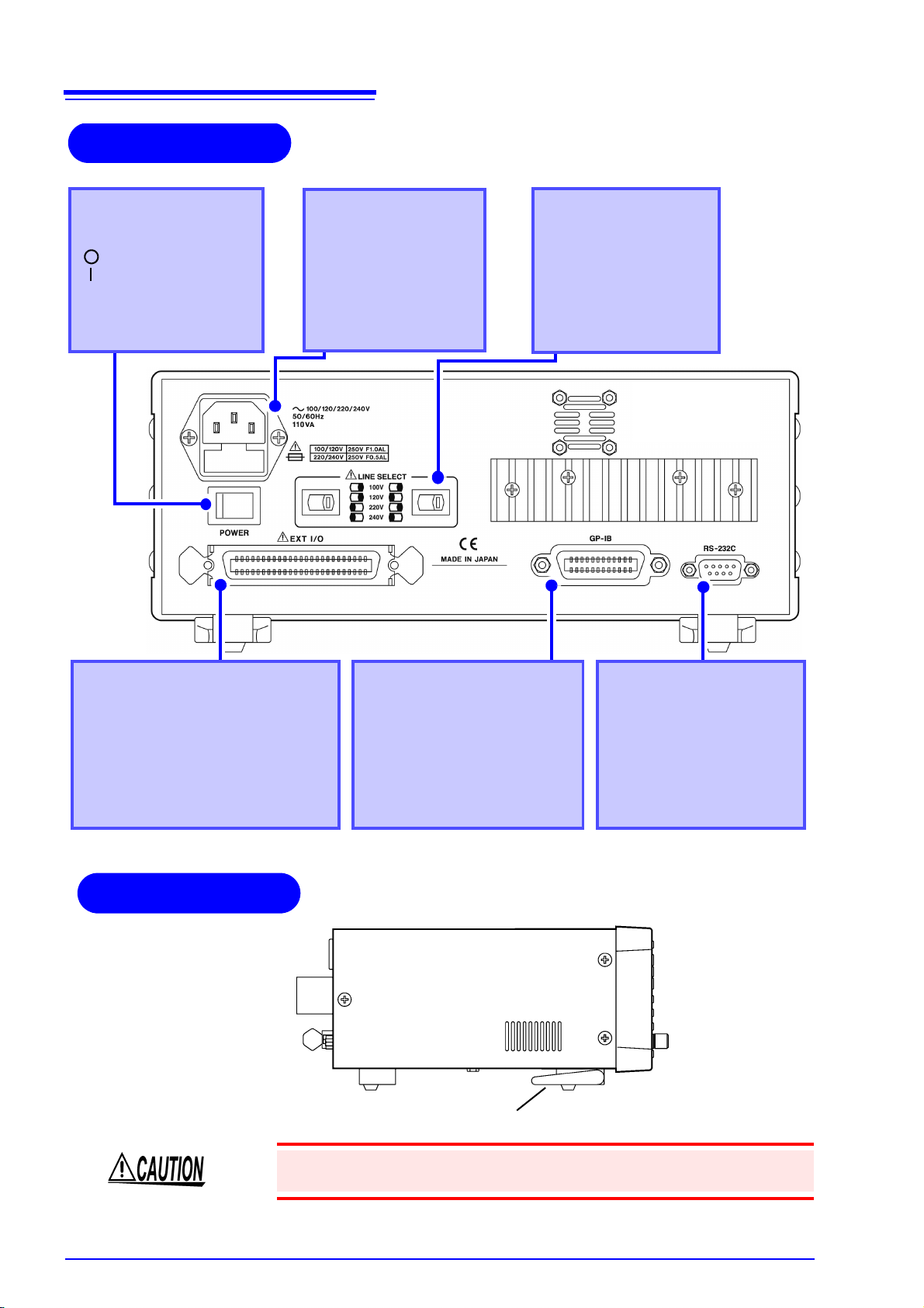
12
Back
GP-IB Connector
(Model 3504-50, 3504-60 only)
Connect a GP-IB cable.
See Chapter 8 "Controlling the
Unit from a PC" (p. 131)
EXT I/O Connector
Inputs external trigger signals and outputs comparator result signals and other
signals. Supports connection to a
sequencer.
See 7.1 "About the EXT I/O Connector"
(p. 123)
Power Switch
Turns the power on and off.
: Turns the power off.
: Turns the power on.
See 2.5 "Turning the Power
On and Off" (p. 21)
RS-232C Connector
Connect an RS-232C cable.
See Chapter 8 "Controlling the
Unit from a PC" (p. 131)
Voltage
Selectors
Changes the power voltage
Power Inlet
Connect the supplied
power cord
See 2.3 "Connecting the
Power Cord" (p. 19)
Stand
Side
Right side
1.4 Names and Functions of Parts
Do not apply heavy downward pressure with the stand extended. The stand
could be damaged.
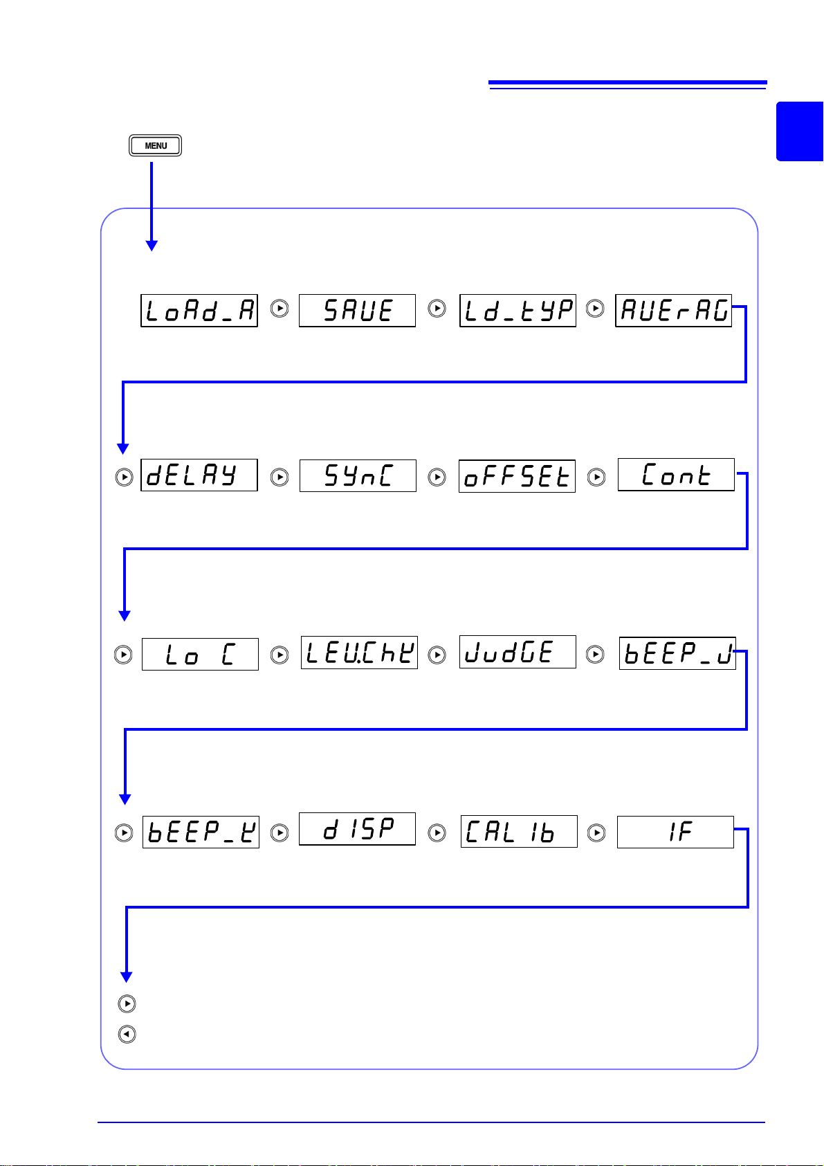
Menu display organization
“LoAd_A(C/h)”
(p. 108)
“dELAY”
(p. 93)
“bEEP_K “
(p. 114)
“SAVE”
(p. 107)
“LEV.ChK“
(p. 98)
“dISP”
(p. 103)
“Ld_tYP“
(p. 108)
“SYnC”
(p. 104)
“JudGE”
(p. 62)
“AVErAG“
(p. 91)
“oFFSEt“
(p. 54)
“bEEP_J”
(p. 112)
Return to Panel Load Function.
(MAIN display area)
Panel Load
Function
Panel Save
Function
Load
Conditions
Average
Function
Trigger Delay
Trigger Synchro-
nous Function
Offset
Compensation
Level Check
Function
Judgment Mode
Beep Tone for
Judgment Results
Display
Beep Tone for
Key Operations
Returns to previous screen.
“IF”
(p. 136)
Communication
Conditions
“Lo C“
(p. 96)
Low C Reject
Function
Contact Check
Function
(Model 3504-60 only)
“Cont”
(p. 100)
“CALIb”
(p. 58)
Self Calibration
13
1.4 Names and Functions of Parts
Displays menu screen
1
9
14
C
1.4 Names and Functions of Parts
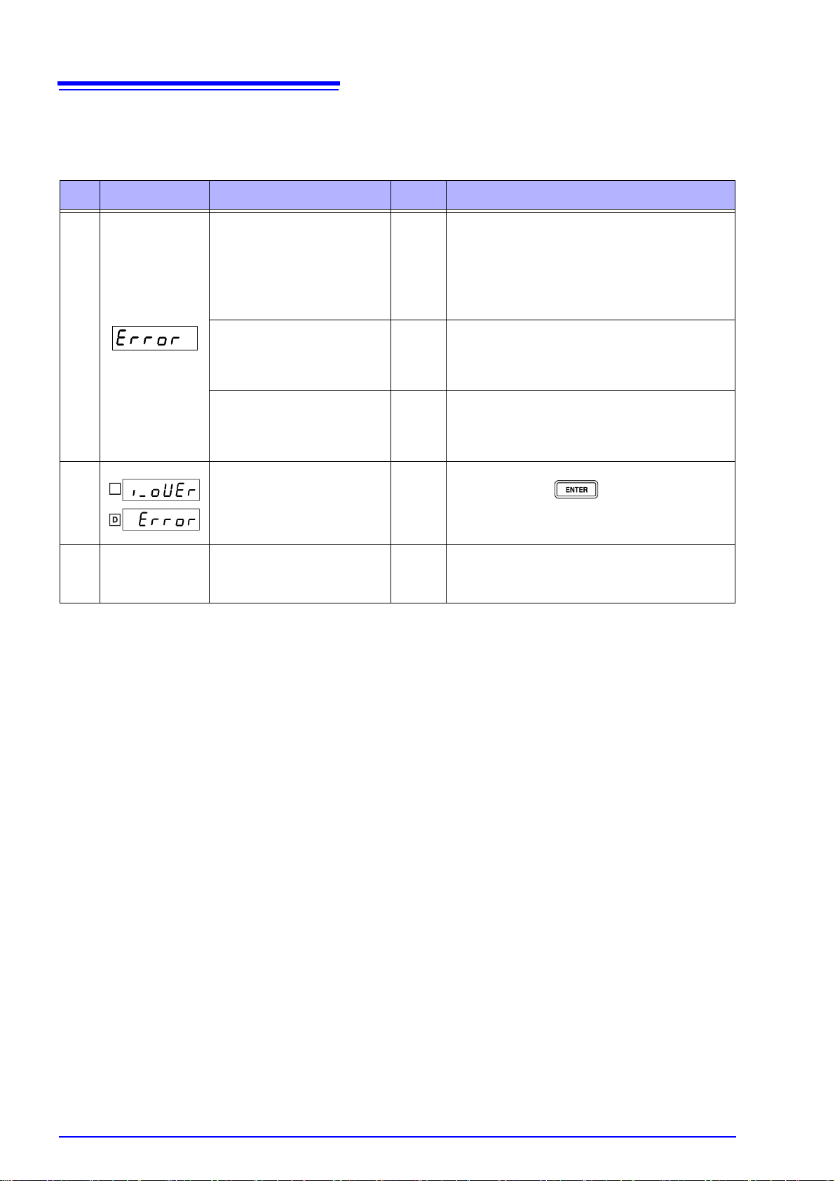
MAIN display area ERROR display
When the 3504-40, 3504-50 and 3504-60 C HiTesters detects a measurement abnormality, an error message is dis-
played in the MAIN display area.When a measurement error occurs, the device's condition is displayed in order of priority
rank in the MAIN display area.When an error display occurs, the comparator and BIN measurement judgment results will
be HI and OUTOF-B
Priority
rank
MAIN display Error content
-
-
-
measurement value
Normal
INS.
OPEN compensation error
Displayed when the OPEN
compensation value is less than
1 k.
See (p. 41)
SHORT compensation error
Displayed when the SHORT
compensation value is more
than 1 k
See (p. 43)
LOAD compensation error
Displayed when the LOAD compensation value is outside of
range.
See (p. 49)
Output current abnormality
Displayed when low impedance elements were connected for more than 10 min.
in range
7 or 8.
ERR LED light on
Acquiring self calibration
abnormal value
See (p. 58)
EXT I/O Solution
• Put the measurement terminals in an open
state. (Short circuit the H
terminal, and the L
H
POT
terminal.)
L
-
-
-
-
ERR
output
Normal
evalua-
tion
POT
• Use the shielding process as a countermeasure
against external noise.
• Earth the device.
• Check to see if the measurement cable is broken.
• Short the measurement terminals.
• Check to see if the measurement cable is broken.
• Perform compensation again after setting to the
appropriate range.
• Put the measurement terminals in an open state
and then press .
• In Range 7 and 8, do not leave low impedance
elements (1 or less) connected. It may result
in damage on the main unit.
• The device is acquiring an abnormal self calibration value. Reconnect the instrument to be
tested correctly and carry out self-calibration
again.
terminal to the
CUR
terminal to the
CUR
15
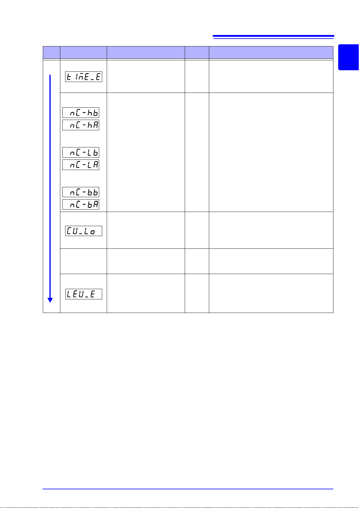
1.4 Names and Functions of Parts
Priority
rank
High
Low
MAIN display Error content
Sampling error
Displayed when the A/D
conversion is not carried out
normally.
Abnormal connection
on the H side
Contact Abnormality
Displayed when the connection
resistance between the measurement terminal and the object to be measured becomes
large.
See (p. 102)
Abnormal connection
on the L side
Abnormal connection
on the H, L side
Applied voltage
abnormality
Displayed when the voltage between the measurement terminals is lower than the measured
voltage.
Low C Connector error
Normal
measurement value
Displayed when the measured
value is abnormally lower than
the measurement range.
Abnormal level detected
Displayed when the inspection
level abnormality monitor value
fluctuates.
See (p. 99)
EXT I/O Solution
ERR
output,
judgment,
OUT
judgment
ERR
output,
judgment,
OUT
judgment
ERR
output,
judgment,
OUT
judgment
ERR
output
Normal
evalua-
ERR
output,
judgment,
OUT
judgment
• It is possible that the device is being affected by
HI
HI
HI
tion
HI
incoming noise.
• Problem with the device.
Submit it for repairs.
• The measurement terminals may not be connected to the object being measured.
Check the contact between the object being
measured and the measurement terminals.
•The H
nected. Check the connection between the
measurement sample and the terminals.
• There may be a high contact resistance
between the H
object being measured.
• The measurement terminals may not be connected to the object being measured.
Check the contact between the object being
measured and the measurement terminals.
• hattering may have occurred.
Check the connection between the measurement sample and the terminals.
It is possible that the device is being affected by
incoming noise.
• Use the shielding process as a countermeasure
agains
POT
and H
CUR
terminals may be discon-
CUR
and L
terminals and the
CUR
1
9

16
1.4 Names and Functions of Parts
Measurement
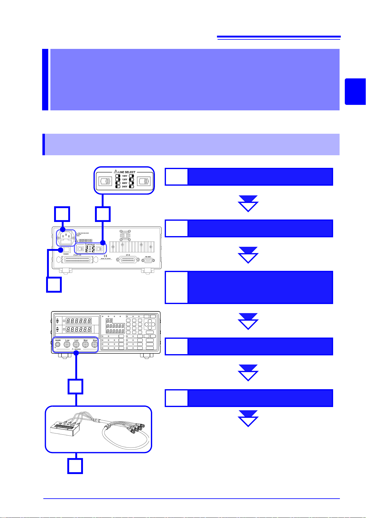
1
Check the power voltage.
See 2.2 "Checking the Power Voltage" (p. 18)
2
Connect the power cord.
See 2.3 "Connecting the Power Cord" (p. 19)
3
Connect the probes or fixture
(option) to the measurement
terminals.
See 2.4 "Connecting the Probes and Fixtures" (p. 20)
4
Turn the power on.
See 2.5 "Turning the Power On and Off" (p. 21)
5
Connect the sample.
Unit Settings and Measurement
See Chapter 3 "Basic Measurement" (p. 23)
See Chapter 4 "Compensate for errors" (p. 37)
See Chapter 6 "Application Functions" (p. 91)
Back
Front
2
3
5
(Example)
Model 9261 Test Fixture
(Option)
4
1
17
2.1 Preparation Flowchart
Preparations Chapter 2
Be sure to read "Operating Precautions" (p. 4) prior to setting up the unit.
2.1 Preparation Flowchart
2
18
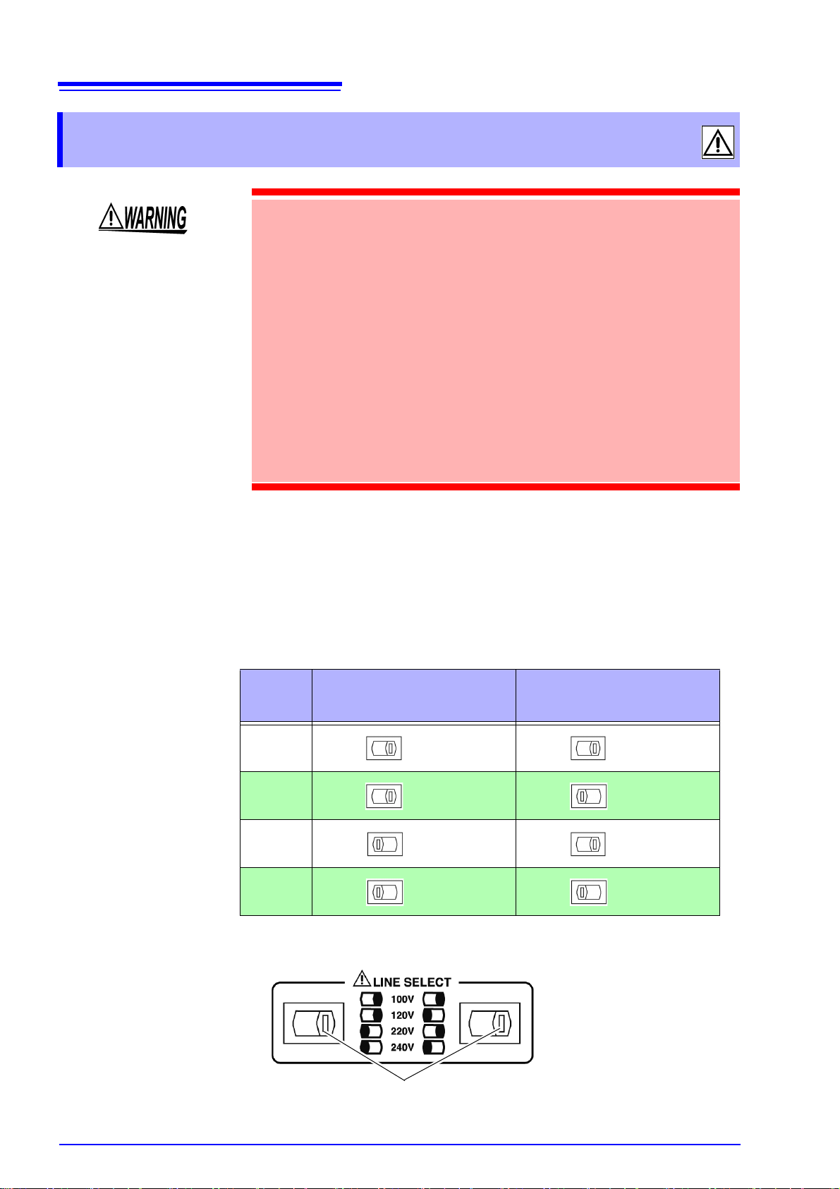
Back
In the diagram, the voltage
value is 100 V because
both the left and right voltage selectors are set to the
right side.
Voltage selectors
2.2 Checking the Power Voltage
2.2 Checking the Power Voltage
• Before turning the unit on, make sure the supply voltage matches that
indicated on the its power connector. Connection to an improper supply voltage may damage the unit and present an electrical hazard.
• The power of the unit can be changed with the voltage selectors. To
avoid an electric accident, use the unit with the voltage selectors set to
a voltage value that matches the voltage to be used.
• Make sure the power is off when you change the voltage with the voltage selectors. Changing the power voltage when the power is on may
result in damage to the unit or an electric accident.
• The maximum rated power is 110 VA.
• Replace the fuse only with one of the specified characteristics and voltage and current ratings. Using a non-specified fuse or shorting the
fuse holder may cause a life-threatening hazard.
Fuse type: 100 V 120 V setting: 250 V F1.0AL 20 mm x 5 mm dia
220 V 240 V setting: 250 V F0.5AL 20 mm x 5 mm dia
See
10.2 "Replacing the Power Fuse" (p. 265)
The power voltage specification of the unit is set as specified when the unit was
ordered.
You can select from 100 V, 120 V, 220 V, and 240 V.
You can determine which voltage is set by checking the positions of the voltage
selectors.
Refer to the diagram between the voltage selectors.
Voltage
100 V
120 V
220 V
240 V
Position of Left Voltage
Selector
(Right side) (Right side)
(Right side) (Left side)
(Left side) (Right side)
(Left side) (Left side)
Position of Right Voltage
Selector
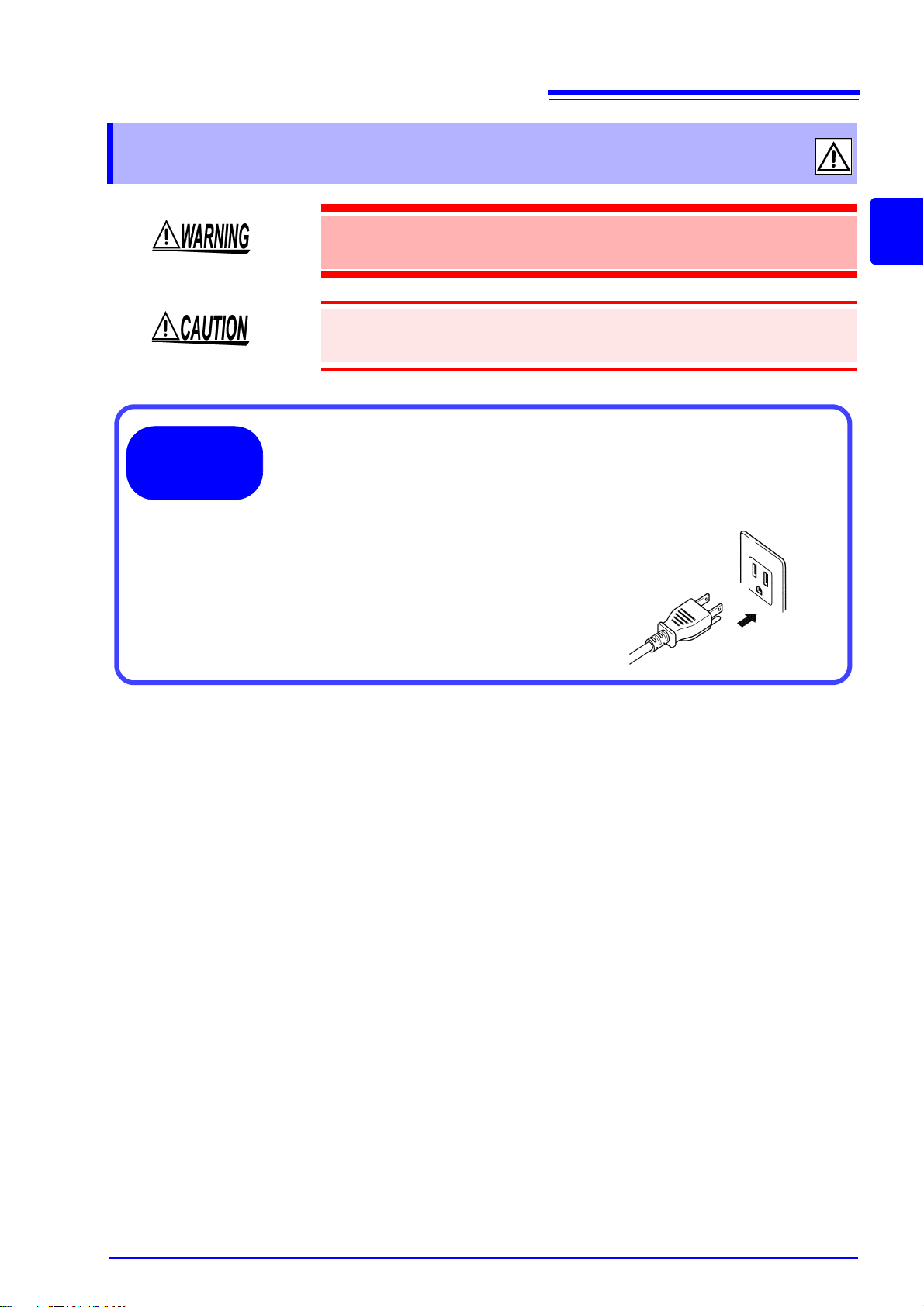
2.3 Connecting the Power Cord
1. Make sure the power switch of the unit is off.
2. Make sure the power voltage matches and connect the power
cord to the power inlet with voltage selectors on the rear of the
unit.
3. Insert the plug into the power outlet.
Connection
Procedure
2.3 Connecting the Power Cord
To avoid electrical accidents and to maintain the safety specifications of
this unit, connect the power cord provide only to a 3-contact (two-conductor + ground) outlet.
• To avoid damaging the power cord, grasp the plug, not the cord, when
unplugging it from the power outlet.
• Turn off the power before disconnecting the power cord.
19
2
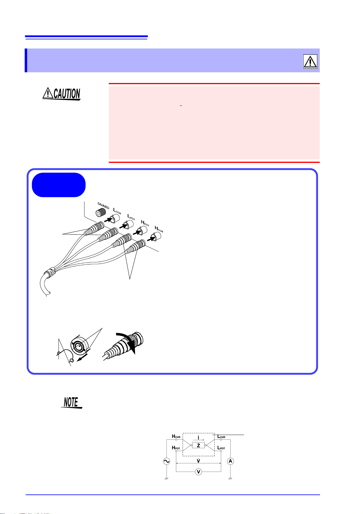
20
Red plugs
Black plugs
Measurement
Terminal
Connect the red plugs to the H
CUR
terminal and
H
POT
terminal and the black plugs to the L
CUR
terminal and L
POT
terminal.
The unit has the following five measurement terminals.
H
CUR
terminal Terminal for applying measurement
signals
H
POT
terminal Voltage detection HIGH terminal
L
POT
terminal Voltage detection LOW terminal
L
CUR
terminal Measurement current detection terminal
GUARD terminal Connect this terminal to the case
Connection
Procedure
Example: Connecting a Model 9261 Test Fixture (Option)
Lock
Align the grooves of the BNC connector with the
connector guides of the connector of the unit
and then insert the connector and rotate it clockwise until it locks into position.
To disconnect the connector, rotate it counterclockwise until it unlocks and then remove it.
3504-40, 3504-50, 3504-60
Measurement Terminal
Connector Guides
9261 Test Fixture
BNC Connector Grooves
Measurement Terminal Connections
21
Fixture
Measurement Terminal
Configuration
2.4 Connecting the Probes and Fixtures
2.4 Connecting the Probes and Fixtures
• Do not apply a voltage to the measurement terminals. Doing so may damage
the unit.
• When disconnecting the
pulling off the connector. Forcibly pulling the connector without releasing the
lock, or pulling on the cable, can damage the connector.
• To avoid breaking the probes, do not bend or pull them.
• The ends of the probes are sharp. Be careful to avoid injury.
• Avoid stepping on or pinching cables, which could damage the cable insulation.
• A voltage of ±12 V is generated at the L
minals are in an open state.
BNC connector, be sure to release the lock before
terminal when the L
CUR
POT
and L
CUR
ter-
For details such as the connection procedure for a fixture, refer to the corresponding instruction manual.
• Use Hioki probes, fixtures (option), etc.
See
• If all four terminals are disconnected, a meaningless number may be dis-
played on the unit.
Appendix 6 "Options" (p. A8)
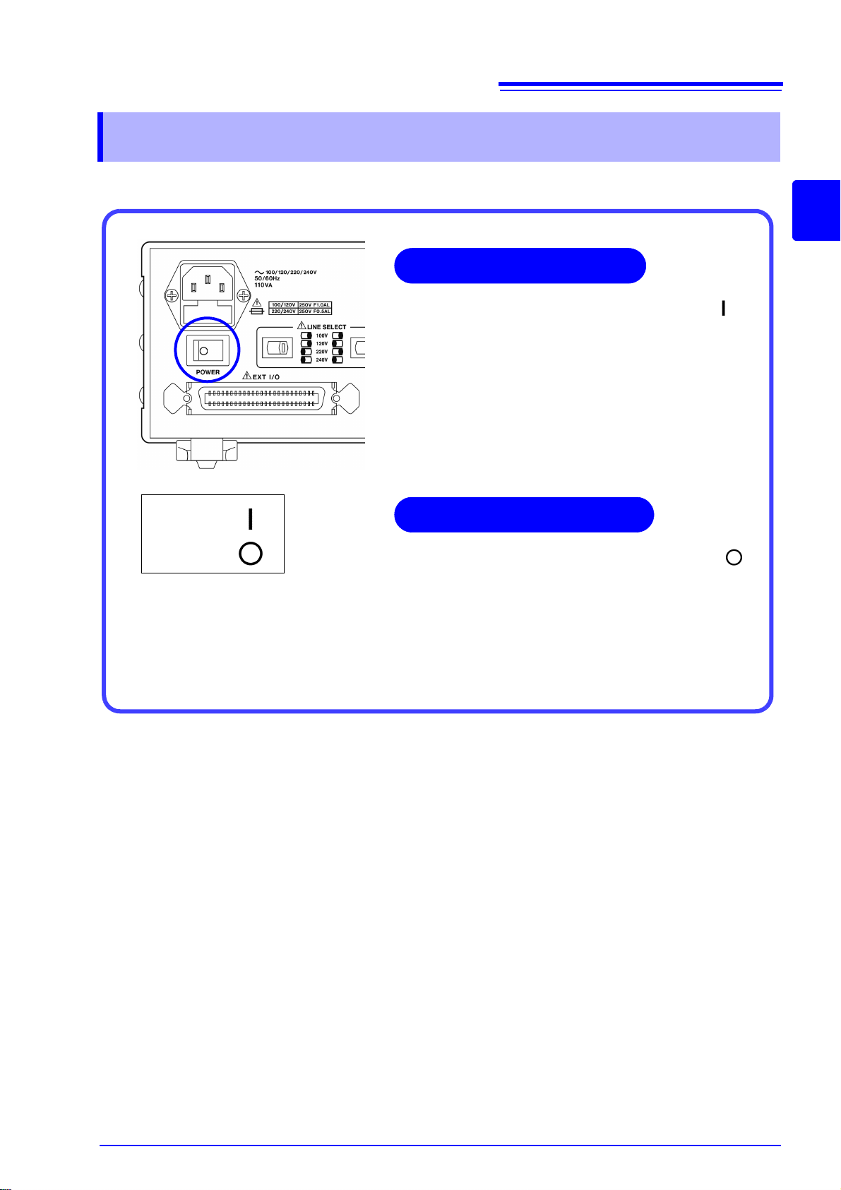
2.5 Turning the Power On and Off
Set the power switch on the rear of the unit to ON ( ).
All LEDs on the front panel light up.
The measurement conditions at startup are the same as
the last time the power was turned off.
After turning the power on, wait 60 minutes for the unit to
warm up before beginning measurement.
Power ON
Power OFF
Turning the power On
Turning the power Off
Set the power switch on the rear of the unit to OFF ( ).
The measurement conditions are saved when the power
is turned off.
Even if there is a power failure or other problem with the
power, the unit will be in the measurement mode prior to
the power failure after it recovers.
I
2.5 Turning the Power On and Off
21
2

22
2.5 Turning the Power On and Off
23
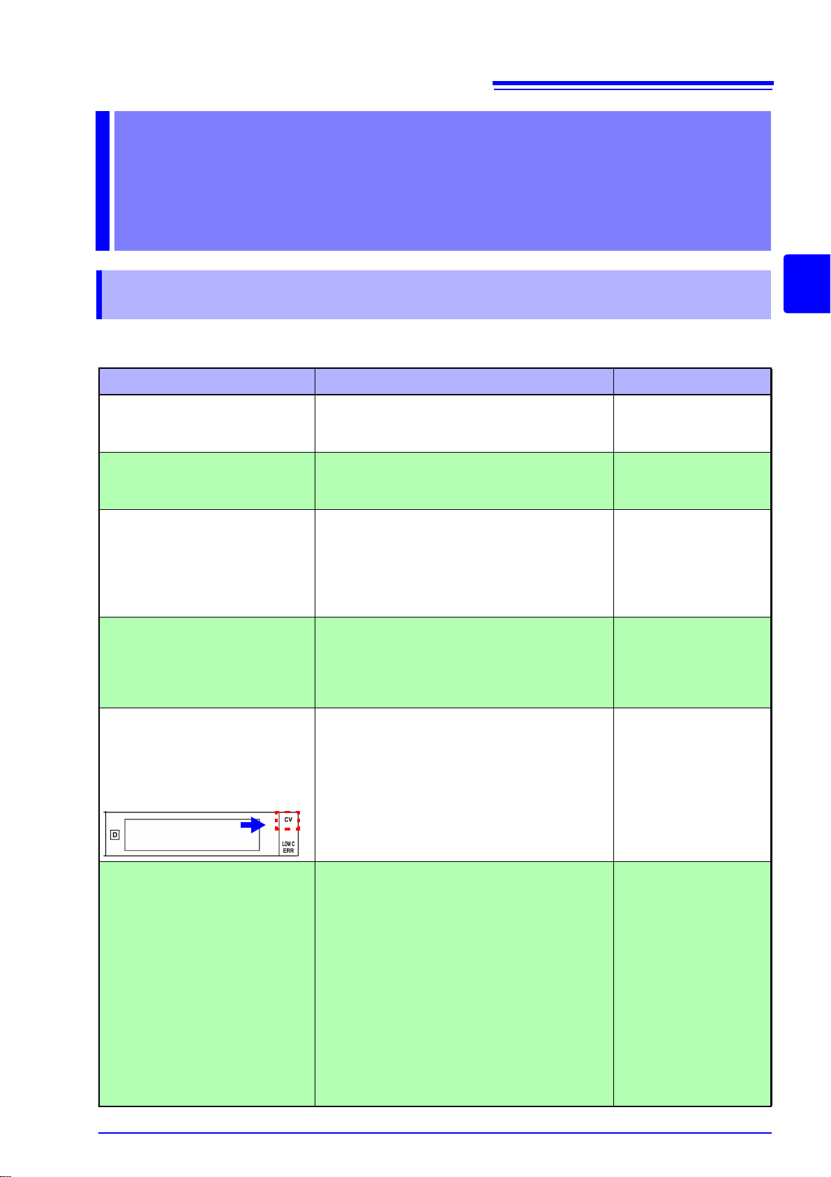
3.1 Pre-Operation Inspection
Basic
Measurement Chapter 3
3.1 Pre-Operation Inspection
To ensure safe use of the unit, be sure to check the following inspection
items prior to performing measurements.
Items Countermeasure See:
Inspect the unit, probe, and fixture
(Are there any damaged parts?)
Inspect the connection cord
(Is the covering cracked or is any
metal exposed?)
Check the power supply voltage
setting
(Does the setting of the voltage
selector on the rear of the unit
match the power supply voltage to
be used?)
When the power is turned on,
does the fan spin and do the
“3504-40, 3504-50, 3504-60” and
version number indications appear on the MAIN display area?
If there is damage:
Unit and fixture: Submit them for repairs.
Probe: Replace it with a new one.
Do not use a damaged cord because doing so
may result in electric shock. (Replace the cord
with a new one.)
Use of the unit outside the specified power supply voltage range may result in the unit being
damaged or an electrical fault. Set the voltage
selector in accordance with the power supply
voltage to be used.
If the fan does not spin or the “3504-40, 350450, 3504-60” and version number indications
are not displayed, the unit may be malfunctioning. Submit it for repairs.
Setting the Voltage
Selector:
2.2 "Checking the
Power Voltage" (p. 18)
3
Does the CV LED light up when
measurement is performed with
the measurement terminals
open while the probe and fixture
are connected to the unit?
(Range: AUTO)
Are the measurement values indicated on the unit normal when
measuring known samples such
as standard capacitors?
If the CV LED does not light up, the unit, probe,
or fixture may be malfunctioning.
Unit and fixture: Submit them for repairs.
Probe: Replace it with a new one.
If the measurement values are abnormal,
check/perform the following.
• Are the measurement conditions set appropriately?
• Perform open circuit and short circuit compensation again.
• Turn load compensation off.
• Set an appropriate trigger delay time or wait
time for trigger synchronous output function.
If the measurement values are still abnormal after you have checked/performed the above, the
unit, probe, or fixture may be malfunctioning.
Unit and fixture: Submit them for repairs.
Probe: Replace it with a new one.
Connecting the Probe
and Fixture:
2.4 "Connecting the
Probes and Fixtures" (p.
20)
3.3 "Setting the Measurement Conditions" (p. 26)
4.1 "Open Circuit Compensation and Short Circuit Compensation" (p. 37)
4.2 "Load Compensation"
(p. 47)
6.2 "Trigger Delay Setting"
(p. 93)
6.5 "Trigger Synchronous
Output Function" (p. 104)
"Setting and Query of
Wait Time for Trigger Synchronous Output Function"
(p. 239)
9
24
2
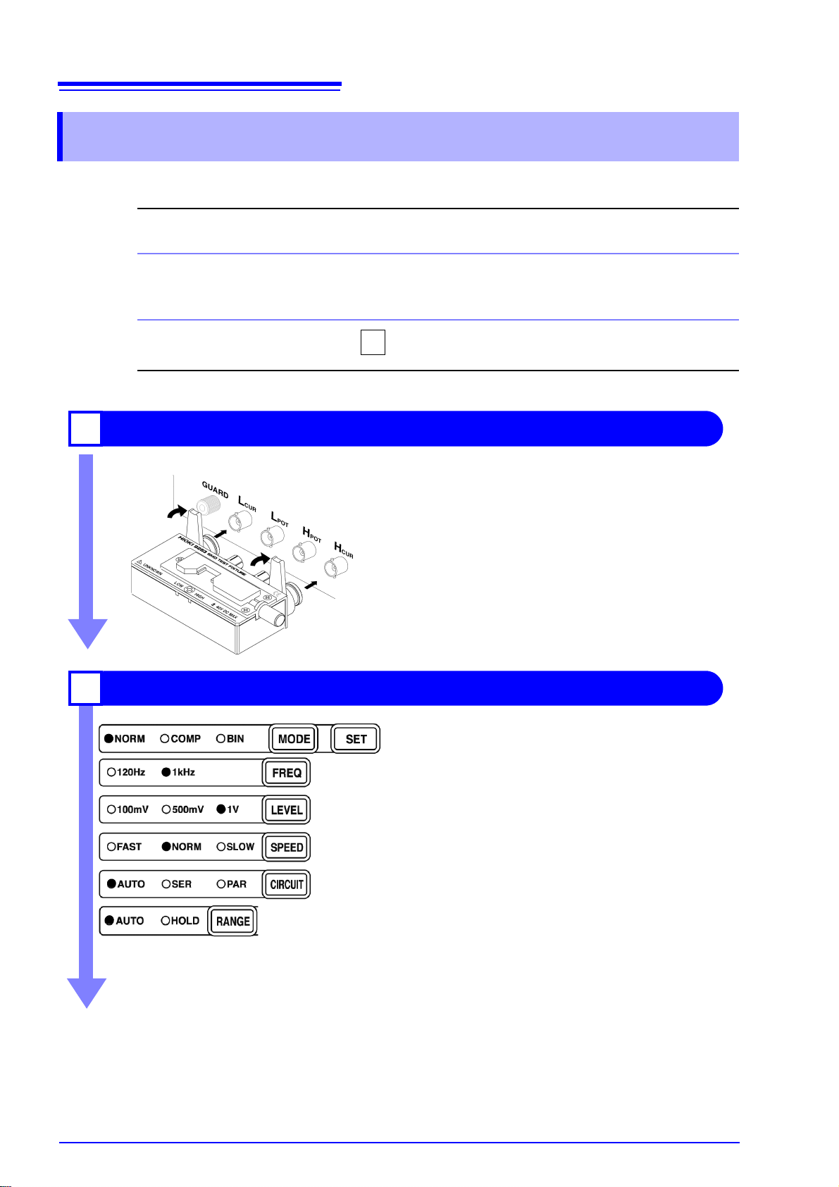
Connect the 9263 SMD Test Fixture (Option).
1
Connect the 9263 SMD Test Fixture to the measurement terminal.
For the connection method, refer to the instruction manual supplied with the fixture.
Set the measurement conditions.
2
Using the keys on the operating panel, set the measurement conditions as shown at left.
Make other settings as necessary.
See
4.1 "Open Circuit Compensation and Short Circuit
Compensation" (p. 37)
See 4.2 "Load Compensation" (p. 47)
See 4.3 "Offset Compensation" (p. 54)
See 4.4 "Self Calibration" (p. 58)
See 6.1 "Setting the Average Function" (p. 91)
See 6.2 "Trigger Delay Setting" (p. 93)
See 3.3.7 "Trigger Signal" (p. 36)
The open circuit compensation, short circuit compensation, load circuit compensation and self calibration
settings improve measurement accuracy.
MODE
Measurement mode........ NORM (p. 26)
FREQ
Frequency......................... 1 kHz (p. 26)
LEVEL
Measurement signal level..... 1 V (p. 27)
SPEED
Measurement speed ....... NORM (p. 28)
CIRCUIT
Equivalent-circuit mode .. AUTO (p. 29)
RANGE
Measurement range......... AUTO (p. 31)
3.2 Measurement Example
3.2 Measurement Example
The following example shows a measurement operation using the 3504-40, 3504-50, 3504-60.
Example
Necessary tools
Measurement
Conditions
The 9263 SMD Test Fixture is used for the measurement
of multilayer ceramic capacitors.
• 3504-40, 3504-50, 3504-60
• 9263 SMD Test Fixture
• Sample to be measured: Multilayer ceramic capacitor
See .
 Loading...