

Page 1

Instruction Manual
3504
3504-10
C HiTESTER
December 2008 Revised edition 2 3504A981-02 08-12H
Page 2

Page 3

Contents
Contents
Introduction.................................................................................1
Verifying Package Contents.......................................... .. ...........1
Safety Informa tio n ............. .. ................. .. ................. ... ................2
Operating Precautions................................................................4
Chapter 1
Overview ___________________________________ 7
1.1 Product Overview ........................................ .. ...............7
1.2 Features .......................................................................7
1.3 Entire Wo r kflow ... .. ... ................ ... .. ................. .. ... .........9
i
1.4 Names and Fu nctions of Parts ....................... .. ... .......11
Chapter 2
Measurement Preparations ____________________ 15
2.1 Preparation Flowchart ................................................15
2.2 Checking th e P ower Voltage.................... .. ................ 16
2.3 Connecting the Power Cord................... .................... 17
2.4 Connecting the Probes and Fixtures............ .............. 18
2.5 Turning the Power On and Off ...................................19
Chapter 3
Basic Measurement__________________________ 21
3.1 Pre-Op e ra t ion In sp e ction .................................... .......21
3.2 Measurement Example ..............................................23
3.3 Setting the Measurement Conditions
(Required Settings) ....................................................25
3.3.1 Measurement Mode ......................................................2 5
3.3.2 Measurement Frequency ......................... .... ..... ............25
3.3.3 Measurement Signal Level ............................................2 6
3.3.4 Measurement Speed .................................... ..... ..... .... ...2 7
3.3.5 Equivalent Circuit Mode ................................................27
3.3.6 Measurement Range ......................................... ..... .......29
3.4 Measurement Conditions (Optional Settings) ............31
3.4.1 Open Circuit Compensation • Short Circuit
Compensation ...............................................................31
3.4.2 Load Compensation ......................................................36
3.4.3 Trigger Signal ................................................................39
Page 4

ii
Contents
Chapter 4
Application Functions_________________________41
4.1 Compara t or Fu n ctio n .............. .. ... ................ ... ........... 41
4.2 BIN Measurement Function (Only for 3504) .............. 50
4.3 Synchronous Measurement Function
(3504 special specification) ....................................... 60
4.4 Trigger Synchronous Output Function ............. .......... 62
4.5 Keylock Function ....................................................... 64
4.6 Panel Save Function ......................... ................... ..... 65
4.7 Panel Load Function ..................... ...................... .. ..... 66
4.8 Printing Function ........................................................ 69
4.8.1 Preparation Prior to Connecting the Printer ..................69
4.8.2 Connection Procedure ..................................................71
4.8.3 Printing ..........................................................................72
Chapter 5
Other Settings ______________________________73
5.1 Setting Beep Tones ............... ....................................73
5.1.1 Setti ng the Beep Tone for Judgment Results of
Comparator and BIN .....................................................73
5.1.2 Setting the Beep Tone for Key Operations ...................74
5.2 Performi n g a Sy ste m Re se t . ................. ... .. ................ 76
5.3 Countermeasures Against Inco rporation of External
Noise ......................................................................... 78
5.3.1 Countermeasures Against Incorporation of Noise from
the Power Line ..............................................................78
5.3.2 Countermeasures Against Incorporation of Noise from
the Input Line (Types of Probe) ....................................79
Chapter 6
Application Measurement______________________81
6.1 Measure m e n t Usin g EX T I/O........................... .. ........ 81
6.1.1 About the EXT I/O Connector .......................................81
6.1.2 Circuit Configuration and Connections of the EXT I/O
Connector..................................................................... 83
6.1.3 About Input and Output Signals ....................................84
6.1.4 About Measurement Times ...........................................86
6.2 Measurement of High Impedance Components ........ 87
6.3 Measurement of In-circuit Components ..................... 88
6.3.1 Measurement Using Guarding Technique ....................88
6.3.2 Synchronous Measurement ..........................................89
Page 5

Contents
Chapter 7
Controlling the Unit from a PC __________________ 91
7.1 Outline and Fe a tu r es .... ... ................. ................ ... .......91
7.2 Specifications .............................................................92
7.2.1 RS-232C Specifications ............................... ..... ..... .... ...92
7.2.2 GP-IB Specifications (Only for 3504) ............................93
7.3 Connection and Setting Procedures ........... ...............94
7.3.1 Connecting the RS-232C Cable / GP-IB Cable .............94
7.3.2 Setting the Interface Communication Conditions ..........96
7.4 Remote Fu nction ............. ................. .. ................. .. ..... 9 8
7.5 Communication Procedure .........................................98
7.6 Things to Know before Beginning Communication ....99
7.6.1 About Message Formats ...............................................99
7.6.2 About the Output Queue and Input Buffer ...................104
7.6.3 About the Status Byte Register ...................................105
7.6.4 About Event Registers ................................................107
iii
7.7 Message List .................... .. ......................................112
7.8 Ability to Use Commands by State ...........................121
7.9 Message Reference ............................... ..................124
7.9.1 Common Commands ..................................................125
7.9.2 Unique Commands ......................................................131
7.9.3 Response Format of Queries for Returning Values ....172
7.10 Initialized Items ........................................................174
7.11 Creating Programs ...................................................175
7.11.1 Creation Procedure .....................................................175
7.11.2 Sample Programs ........................................................178
7.12 Troubleshooting the Interface ......................... .........181
7.13 Device Document Requirements
(Only for the 3504 ) ............ ................. ................. .. ...183
Chapter 8
Specifications______________________________ 187
8.1 Basic Specifications .................................................187
8.2 Accuracy ..................................................................190
8.3 Measurement Parameters and Arithmetic
Expressions .. ......... ............ ............ ............ .......... ..... 19 2
Page 6

iv
Contents
Chapter 9
Maintenance and Service_____________________195
9.1 Inspection, Repair, and Cleaning ............................195
9.2 Replac in g th e Powe r Fu se ............. ................. .. ...... 197
9.3 Discarding the Unit ...................... .. ................. .. ... .. .. 198
Chapter 10
Options___________________________________199
Appendix _________________________________ A1
Appendix 1 Mounting the Unit in a Rack..............................A1
Appendix 2 External View..................... ................... ............A3
Index__________________________________ Index i
Page 7

Introduction
Thank you for purchas ing the HIOKI “Model 3504, 3504-10 C HiTester.” To
obtain maximum performance from the unit, please read this manual first, and
keep it handy for future reference.
Verifying Package Content s
When you receive the unit, inspect it carefully to ensure that no damage
occurred during shipping. In particular, check the accessories, panel
switches, and connectors. If damage is evident, or if it fails to operate according to the specifications, contact your dealer or Hioki representative.
This unit 3504 C HiTester
3504-10 C HiTester
1
Introduction
Accessories • Instruction Manual.............................................................................. 1
• Power cord......................................................................................... 1
• Spare fuse for power supply (according to voltage specification) ......1
100 V, 120 V setting : 250 V F 1.0 AL 5 x 20 mm dia
220 V, 240 V setting : 250 V F 0.5 AL 5 x 20 mm dia
Probes, fixture are not supp lied with the unit as standard equipment. You
should order them separately, according to requirements.
Shipping precautions
Use the original packing materials when transporting the unit, if possible.
Options
Chapter 10 "Options" (p. 199)
About Special Specifications
These specifications are not included in standard products.
Page 8

2
Safety Information
Safety Information
This unit is designed to comply with IEC 61010 Safety Standards, and
has been thoroughly tested for safety prior to shipment. However, mishandling during use could result in injury or death, as well as damage
to the unit. Be certain that you understand the instructions and precautions in the manual before use. We disclaim any responsibility for accidents or injuries not resulting directly from unit defects.
This manual contains information and warnings essential for safe operation of
the unit and for m aintaining it in s afe operating condition. B efore using i t, be
sure to carefully read the following safety precautions.
Safety Symbols
In the manual, the symbol indicates particularly important
information that the user should read before using the unit.
The symbol printed on the unit indicates that the user should
refer to a corresponding topic in the manual (marked with the
symbol) before using the relevant function.
Other Symbols
Indicates AC (Alternating Current).
Indicates a grounding terminal.
Indicates a fuse.
Indicates the ON side of the power switch.
Indicates the OFF side of the power switch.
The following symbol s in this manu al indicat e the rela tive importance of c autions and warnings.
Indicates that incorrect operation presents a significant hazard that could result in serious inju ry or death to the user.
Indicates that inc orrect operation presents a possi bility of
injury to the user or damage to the unit.
Indicates advisory items related to performance or corr ec t
operation of the unit.
Indicates a prohibited action.
Indicates the location of reference information.
Indicates quick references fo r operati on and remed ies for
troubleshooting.
*
Indicates that descriptive information is provided below.
Page 9

Measurement Categories (Overvoltage categories)
To ensure safe operation of measurement units, IEC 60664 establishes
safety standards fo r various electrical environ ments, catego rized as CAT I to
CAT IV, and called overvoltage categories. These are defined as follows.
CAT I: Secondary electrical circuits connected to an AC elec-
trical outlet through a transformer or similar device.
CAT II: Primary electrical cir cuits in equipment connected to
an AC electrical outlet by a power cord (portable tools,
household appliances , etc.)
CAT III: Primary electrical circuits of heavy equipment (fixed
installations) connected directly to the distribution
panel, and feeders from the distributi on panel to outlets.
CAT IV: The circuit from the service drop to the service
entrance, and to t he power meter and primary overcurrent protection device (distribution panel).
3
Safety Information
Accuracy
Higher-numbered categories correspond to electrical environments with
greater momentary ener gy. So a meas urement device designed for CAT III
environments can endur e greater mo mentary en ergy than a de vice design ed
for CAT II.
Using a measurement uni t in an environment desig nated with a high er-numbered category than that for which the unit is rated could result in a severe
accident, and must be carefully avoided.
We define measuremen t t olera nces in ter m s of rdg . (r eadin g) and dgt . ( di git) va lues, with the following meanings:
rdg.
(reading or displayed value)
The value currently bei ng measured and
indicated on the measuring unit.
dgt. (resolution) The smallest dis playable unit o n a digital
measuring unit/ device/ product, i.e., the
input value that cau ses the digi tal display
to show a "1" as the least-significant digit.
Page 10

4
Operating Precautions
Operating Precautions
Follow these precautions to ensure safe operation and to obtain the full benefits of the various functions.
Unit Installat ion
Operating Temperature and Humidity: 0 to 40°C), 80%RH or less, no con-
densation
Storage Temperature and Humidity: -10 to 55
sation
Accuracy-guaranteed temperature and humidity ranges: 23
Avoid the following locations that could cause an accident or damage
to the unit.
°C, 80%RH or less, no conden-
±5°C, 80%RH
Installing
Exposed to direct s unlight
Exposed to high temperature
Exposed to liquids
Exposed to high humidity or condensation
Exposed to high levels of particulate dust
• Do not install the unit with any side except the bottom facing down.
In the presence of corrosive or explosive
gases
Exposed to strong
electromagnetic fields
Near electromagnetic
radiators
Subject to vibration
OK
• Vents must not be obstructed.
5 cm or more
10 cm or more
Page 11

Operating Precautions
• To avoid dam age to the unit, protec t i t from physical shock whe n t ra nspor ting and handling. Be especially c areful to avoid physical shock fr om dropping.
• Do not apply heavy downward pressure with the stand extended. The stand
could be damaged.
Handling this device
Never modify the unit. Only Hioki service engineers should disassemble or repair the unit. Failure to observe these precautions may result in
fire, electric shock, or injury.
5
If anything unusual happens during operation of the unit, turn off the
power switch immediately and contact any HIOKI service facility for
help, advice and service.
Before connection and powering on
• Before turning the unit on, make sure the supply voltage matches
that indicated on the its power connector. Connection to an impr oper
supply voltage may damage the unit and present an electrical hazard.
• The power supply voltage for this unit is switchable. To avoid electrical accidents, check that t he voltage selector is set correctly for the
supply voltage you are using.
Setting Procedure for the Power V olt age : 2.2 "Che ckin g the Power Voltage" (p.
16)
• T o avoid electrical accidents and to maintain the safety specifications
of this unit, connect the power cord only to a 3-contact (two-conductor + ground) outlet.
Connection Procedure : 2.3 "Connecting the Power Cord" (p. 17)
• To avoid shock and short circuits, turn off all power before connecting probes.
Check the connections carefully in order to avoid any chance of setting
up a short-circuit etc.
Page 12

6
Operating Precautions
About the guarantee
Preliminary Checks
You sho uld be aware that HIOKI cannot ac cept any responsibil ity directly or
indirectly if the unit has been incorporated in some other s ystem, or if it is
resold to a third party.
Before using the u nit the first time , verify that it o perates normally to ensure
that the no damage occurre d durin g storage or shipping. If you find any damage, contact your dealer or Hioki representative.
Before using the unit, make sure that the insulation on the probes and
cables is undamaged and that no bare conductors are improperly
exposed. Using the unit in such conditions could cause an electric
shock, so contact your dealer or Hioki representative for replacements.
Page 13

1.1 Product Overview
Overview Chapter 1
1.1 Product Overview
The HIOKI Model 3504 and 3504-10 C HiTesters are capacitance meters
employing 120 Hz an d 1 kHz frequencies to measure capacitors other th an
electrolysis capacitor s (Capacitor s other t han the n on-electr olytic capaci tors)
at high speed and hi gh accur acy. Primary application s inclu de pass- fail judgment and ranking of capacitors on tape machines and sorters.
1.2 Features
7
1
Capacitance-specific units
These capacitance meters use 120 Hz and 1 kHz measurement frequencies.
High-speed measurement
The 3504 and 3504-10 are capable of high-speed measurement: 2 ms at
measurement frequency 1 kHz, and 10 ms at 120 Hz.
Constant-voltage measurements
Provides constant-volta ge mea sure men t capabil ity.
(With 1 kHz selected) 1V: to 70 μF 500 mV: to 170 μF
(With 120 Hz selected) 1V: to 700 μF 500 mV: to 1.45 mF
Bin sorting function (Model 3504 only)
Capacitors are easil y ranked according to C (Capacitance *1) measurement
values into as many as 14 classifications.
Comparator function
Easily perform pass-fail judgment of components according to measurements
of both C and D (Dissipation Factor*2).
LED display
Provides superior visibility.
Equipped with standard data transfer interfaces
The 3504 offers external I/O for sequencing, a s tandard RS-232C interface,
and a standard GP-IB interface (Model 3504 only).
Page 14

8
1.2 Features
Measurement value memory
Up to 200 measurement values can be stored in memory.
Trigger-synchronous measurement capability
The measurement signal can be input to the sample in sync with a trigger.
Synchronous measurement (Special feature of Model
3504)
Synchronize multiple meters to reduce interference-induced measurement
instability.
*1. Capability to store electric charge.*2. An indicator of capacitor losses.
Page 15

1.3 Entire Workflow
9
1.3 Entire Workflow
Measurement
Chapter 2 "Measurement Preparations" (p. 15)
Preparations
1.Check the power voltage.
2.Connect the power cord.
3.Connect the probes or fixture (option) to the measurement terminals.
4.Turn the power on.
5.Connect the sample.
Pre-Operation
3.1 "Pre-Operation Inspection" (p. 21)
Inspection
Be sure to perform pre-operation inspection prior to measurement.
Basic Measurement 3.2 "Measurement Example" (p. 23)
1.Prepare the unit, fixture, and sampl e.
2.Connect the fixture to the measurement term inals.
3.Set the measurement conditions.
4.Connect the sample to the fixture.
5.Check the measurement results.
Application Functions Chapter 4 "Application Functions" (p. 41), Chapter 7 "Controlling the Unit from a
PC" (p. 91)
Function Description
Comparator measurement function
BIN measurement
function
(only for 3504)
Synchronous measurement function
(special specification
for 3504)
Trigger synchronous output function
Key lock function Disable key operations.
Communication
function
Panel save function Save measurement conditions.
Panel load function Load saved measurement condi-
Printing function Print measurement values.
Set the upper limit and lower limit
values and judge whether samples
pass or fail.
Set variations of the upper limit
and lower limit values and rank
samples accordingly.
Reduce the differences in measurement values caused by interference when using multiple 3504
units for measurement.
Apply the measurement signal
only during measurement to reduce the generation of heat in the
sample and decrease electrode
wear.
Control the unit from a PC.
tions
Reference
Section
4.1 (p. 41)
4.2 (p. 50)
4.3 (p. 60)
4.4 (p. 62)
4.5 (p. 64)
Chapter 7 (p. 91)
4.6 (p. 65)
4.7 (p. 66)
4.8 (p. 69)
1
Page 16

10
1.3 Entire Workflow
Application
Measurement
Chapter 6 "Application Measurement" (p. 81)
Measurement using EXT I/O
Measurement of high impedance components
Measurement of components in circuit networks
Other Settings Chapter 5 "Other Settings" (p. 73)
Beep tone setting
Reset of system
Countermeasures against incorporation of external noise
Page 17

1.4 Names and Functions of Parts
1.4 Names and Functions of Parts
Front
SUB Display
Displays the limit values of
BIN (only for 3504) and
comparator.
11
1
Comparator Evaluation
Result Display
Displays evaluation results in
Comparator Mode.
4.1 "Comparator Function" (p.
41)
MAIN Display
Displays the measurement
values of C and D.
Displays the MENU items.
Setting Condition
Display
Displays current measurement conditions, presettings, and other information.
*BIN (3504 only)
BIN Judgment Result
Display (only for 3504)
Displays judgment results in
BIN mode.
4.2 "BIN Measurement Func-
tion (Only for 3504)" (p. 50)
Measurement Terminals
There ar e five measurement terminals:
H
CUR
H
POT
L
POT
L
CUR
GUARD Guard terminal
2.4 "Connecting the Probes and
Fixtures" (p. 18)
Measurement-signal
input terminal
Detected voltage high
terminal
Detected voltage low
terminal
Measurement current
detected terminal
Operating Panel
Use to set measurement
conditions and to make other
settings
(⇒ p. 12)
Page 18

12
1.4 Names and Functions of Parts
Operating Panel
Keypad
Used to enter numeric values.
Measurement mode
setting
(⇒ p. 25)
Comparator and BIN
measurement function settings
4.1 "Comparator
Function" (p. 41),
4.2 "BIN Measurement Function
(Only for 3504)" (p.
50)
Arrow keys
Used to change settings and move to
menu items or digits.
Enter
Measurement range
setting
(⇒ p. 29)
Lock/ Local
(⇒ p. 64)
Menu
Manual trigger
(⇒ p. 39)
Measurement frequency setting
(⇒ p. 25)
Measurement signal level setting
(⇒ p. 26)
Measurement speed setting
(⇒ p. 27)
Equivalent circuit mode
(⇒ p. 27)
Measurement range setting
(⇒ p. 29)
Open short circuit compensation
(⇒ p. 31)
Load compensation setting
(⇒ p. 36)
Trigger mode setting
(⇒ p. 39)
Page 19

Back
Power Inlet
Connect the supplied
power cord
2.3 "Connecting the
Power Cord" (p. 17)
Voltage
Selectors
Changes the power
voltage
I
1.4 Names and Functions of Parts
Phase Synchronization Connector
(Special Spec ification)
Connect this to another 3504 (3504-10) unit when performing synchronous measurement.
4.3 "Synchronous Measurement Function (3504 special
specification )" (p. 60)
13
1
Power Switch
Turns the power on and
off.
: Turns the power off.
: Turns the power on.
2.5 "Turning the Power
On and Off" (p. 19)
Side
Left side
EXT I/O Connector
Inputs external trigger signals and outputs comparator
result signals and other signals. Supports connection to
a sequencer.
6.1 "Measurement Using
EXT I/O" (p. 81)
GP-IB
Connector
(only for 3504)
Connect a GP-IB
cable.
Chapter 7 "Control-
ling the Unit from a
PC" (p. 91)
Right side
RS-232C
Connector
Connect an RS-232C
cable.
Chapter 7 "Controlling
the Unit from a PC" (p.
91)
Stand
Do not apply heavy downwar d pressure with the stand e xtended. The stand
could be damaged.
Page 20

14
1.4 Names and Functions of Parts
Page 21

2.1 Preparation Flo wchart
Measurement
Preparations Chapter 2
15
Be sure to read "Operating Precautions" (p. 4) prior to setting up the unit.
2.1 Preparation Flowchart
Check the power voltage.
Connect the power cord.
Connect the probes or fixture
(option) to the measurement
4
2
1
2.2 "Checking the Power Voltage" (p. 16)
1
Back
2
2.3 "Connecting the Power Cord" (p. 17)
3
Front
2.4 "Connecting the Probes and Fixtures" (p. 18)
2
terminals.
(Example)
3
Model 9261 Test Fixture
(Option)
5
4
2.5 "Turning the Power On and Off" (p. 19)
5
Unit Settings and Measurement
Chapter 3 "Basic Measurement" (p. 21)
Chapter 4 "Application Func tions" (p. 41)
Chapter 6 "Application Measurement" (p. 81)
Turn the power on.
Connect the sample.
Page 22

16
2.2 Checking the Power Voltage
2.2 Checking the Power Voltage
• Before turning the unit on, make sure the supply voltage matches
that indicated on the its power connector. Connection to an improper
supply voltage may damage the unit and present an electrical hazard.
• The power of the unit can be changed with the voltage selectors. To
avoid an electric accid ent, use t he unit wit h the voltage sele ctors set
to a voltage value that matches the voltage to be used.
• Make sure the power is off when you change the voltage with the voltage selectors. Changing the power voltage when the power is on may
result in damage to the unit or an electric accident.
• The maximum rated power is 110 VA.
The power voltage spec ification of the un it is set as spec ified when the uni t
was ordered.
You can select from 100 V, 120 V, 220 V, and 240 V.
You can determine which voltage is set by checki ng the positi ons of the vo ltage selectors.
Refer to the diagram between the voltage select or s.
Voltage
100 V Right side Right side
120 V Right side Left side
220 V Left side Right side
240 V Left side Left side
Back
Position of Left Voltage
Selector
Voltage selectors
Position of Right Voltage
Selector
In the diagram, the voltage
value is 100 V because
both the left and right voltage selectors are set to the
right side.
Page 23

2.3 Connecting the Power Cord
2.3 Connecting the Power Cord
To avoid electrical acc idents and to maintain the safety specifications
of this unit, connect the power cord only to a 3-contact (two-conductor
+ ground) outlet.
• To avoid damaging the power cord, grasp the plug, not the cord, when
unplugging it from the power outlet.
• Turn off the power before disconnecting the power cord.
17
2
Connection
Procedure
1. Make sure the power switch of the unit is off.
2. Make sure the power voltage matches and connect the power
cord to the power inlet with voltage selectors on the rear of the
unit.
3. Insert the plug into the power outlet.
Page 24

18
Measurement Terminal
2.4 Connecting the Probes and Fixtures
2.4 Connecting the Probes and Fixtures
• Do not apply a voltage to the measur ement ter minals. Doing so may damage the unit.
• When disconnectin g the
pulling off the connector. Forcibly pulling the connector without releasing
the lock, or pulling on the cable, can damage the connector.
• To avoid breaking the probes, do not bend or pull them.
• The ends of the probes are sharp. Be careful to avoid injury.
• Avoid stepping on or pinching cables, which could damage the cable insulation.
• A voltage of ±12 V is generated at the L
terminals are in an open state.
BNC connector, be sure to release the lock before
terminal when the L
CUR
POT
and L
CUR
Connection
Example: Connecting a Model 9261 Test Fixture (Option)
Procedure
Black plugs
Red plugs
Measurement Terminal Connections
3504 (3504-10) Measurement Terminal Connector Guides
9261 Test Fixture
BNC Connector Grooves
Measurement
Terminal
Lock
21
Connect the red plugs to the H
and H
the L
The unit has the following five measurement
terminals.
H
CUR
H
POT
L
POT
L
CUR
GUARD terminal Connect this terminal to the
Align the grooves of the BNC connector with the
connector guides of the connector of the unit
and then insert the connector and rotate it clockwise until it locks into position.
To disconnect the connector, rotate it counterclockwise until it unlocks and then remove it.
terminal and the black plugs to
POT
terminal and L
CUR
terminal Terminal for applying measure-
ment signals
terminal Voltage detection HIGH termi-
nal
terminal Voltage detection LOW termi-
nal
terminal Measurement current detection
terminal
case
terminal.
POT
CUR
terminal
Configuration
For details such as the connectio n procedure for a fixtu re, refer to the corr esponding instruction manual.
• Use Hioki probes, fixtures (option), etc.
Chapter 10 "Options" (p. 199)
• If all fou r te rmina ls ar e disc on nec ted , a mea ni ngl es s nu mbe r m ay be di splayed on t he unit.
Fixture
Page 25

2.5 Turning the Power On and Off
2.5 Turning the Power On and Off
Turning the power On
Set the power switch on the rear of the unit to ON
().
19
2
Power ON
Power OFF
I
All LEDs on the front panel light up.
The measurement condi tions at startup are the same
as the last time the power was turned off.
After turning the power on, wait 60 minutes for the un it
to warm up before beginning measurement.
Turning the powe r Off
Set the power switch on the rear of the unit to OFF
().
The measurement conditions are saved when the
power is turned off.
Even if there is a power fail ure or other problem with
the power, the unit will be in the measurement mode
prior to the power failure after it recovers.
Page 26

20
2.5 Turning the Power On and Off
Page 27

21
3.1 Pre-Operation Inspection
Basic
Measurement Chapter 3
3.1 Pre-Operation Inspection
To ensure safe use of the unit, be sure to check the following inspection
items prior to performing measurements.
Items Countermeasure See:
3
Inspect the unit, probe, and
fixture
(Are there any damaged
parts?)
Inspect the connection cord
(Is the covering c racked or is
any metal exposed?)
Check the power supply voltage setting
(Does the setting of the voltage selector on the rear of
the unit match the power
supply voltage to be used?)
When the power is turned
on, does the fan spin and do
the “3504 (3504-10)” and
version number indications
appear on the MAIN display
area?
Does the CV LED light up
when measurement is performed with the measurement terminals open while
the probe and fixture are
connected to th e un it ?
(Range: AUTO)
If there is damage:
Unit and fixture: Submit them for repairs.
Probe: Replace it with a new one.
Do not use a damaged cord because doing so
may result in electric shock. (Replace the cord
with a new one.)
Use of the unit outside the specified power supply voltage range may result in the unit being
damaged or an electrical fault. Set the voltage
selector in accordance with the power supply
voltage to be used.
If the fan does not spin or the “3504 (3504-10)”
and version number indications are not displayed, the unit may be malfunctioning. Submit
it for repairs.
If the CV LED does not light up, the unit, probe,
or fixture may be malfunctioning.
Unit and fixture: Submit them for repairs.
Probe: Replace it with a new one.
_______________
_______________
Setting the Voltage Selector:
2.2 (page 16)
_______________
Connecting the Probe
and Fixture:
2.4 (page 18)
Page 28

22
3.1 Pre-Operation Inspection
Items Countermeasure See:
Are the measur ement values
indicated on the unit normal
when measuring known
samples such as standard
capacitors?
If the measurement values are abnormal, check/
perform the following.
• Are the me asurement conditions set appropriately?
• Perform open circuit and short circuit compensation again.
• Turn load compensation off.
If the measurement values are still abnormal after you have checked/performed the above, the
unit, probe, or fixture may be malfunctioning.
Unit and fixture: Submit them for repairs.
Probe: Replace it with a new one.
• Measurement Conditions:
3.3.2 (page 25)
3.3.3 (page 26)
3.3.4 (page 27)
3.3.5 (page 27)
3.3.6 (page 29)
•
Open Circuit Compensation and Short
Circuit Compensation
:
3.4.1 (page 31)
Load Compensation:
•
3.4.2 (page 36)
Page 29

3.2 Measurement Example
e
-
-
The following example shows a measurement operation using the 3504
(3504-10)
Example The 926 3 SMD Te st Fi xture i s used for the measurement of mul-
tilayer ceramic capacitors.:
Necessary tools • 3504 (3504-10)
• 9263 SMD Test Fixture
• Sample to be measured: Multilayer ceramic capacitor
.
23
3.2 Measurement Example
Measurement
See .
2
Conditions
Connect the 9263 SMD Test Fixture (Option).
1
Connect the 9263 SMD Test Fixture to the
measurement terminal.
For the connection method, refer to the instruction manual supplied with the fixture.
Set the measurement conditions.
2
Using the keys on the oper ating p an el, set th
measurement conditions as shown at left.
3
MODE
FREQ
LEVEL
SPEED
CIRCUIT
RANGE
Make other settings as necessary.
3.4.1 "Open Circuit C omp ensati on • Short Circ uit Com pen
sation" (p. 31)
3.4.2 "Load Compensation" (p. 36)
3.4.3 "Trigger Signal" (p. 39)
The open circuit compensation and short circuit co m
pensation settings improve measurement accuracy.
Measurement mode........ NORM
Frequency......................... 1 kHz
Measurement signal level.....1 V
Measurement speed....... NORM
Equivalent-circuit mode .. AUTO
Measurement range......... AUTO
(⇒ p. 25)
(⇒ p. 25)
(⇒ p. 26)
(⇒ p. 27)
(⇒ p. 27)
(⇒ p. 29)
Page 30
24
3.2 Measurement Example
Connect the sample to be measured to the 9263 SMD Test Fixture.
3
For the connection method, refer to the instruction manual supplied with the fixture.
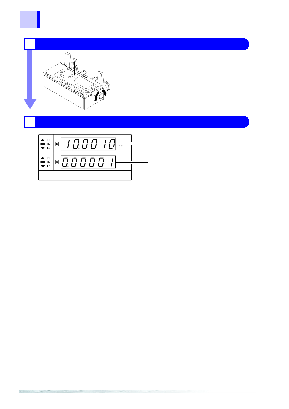
Check the measurement results.
4
C
D
Page 31
3.3 Setting the Measurement Conditions (Required Settings)
3.3 Setting the Measurement Conditions
(Required Settings)
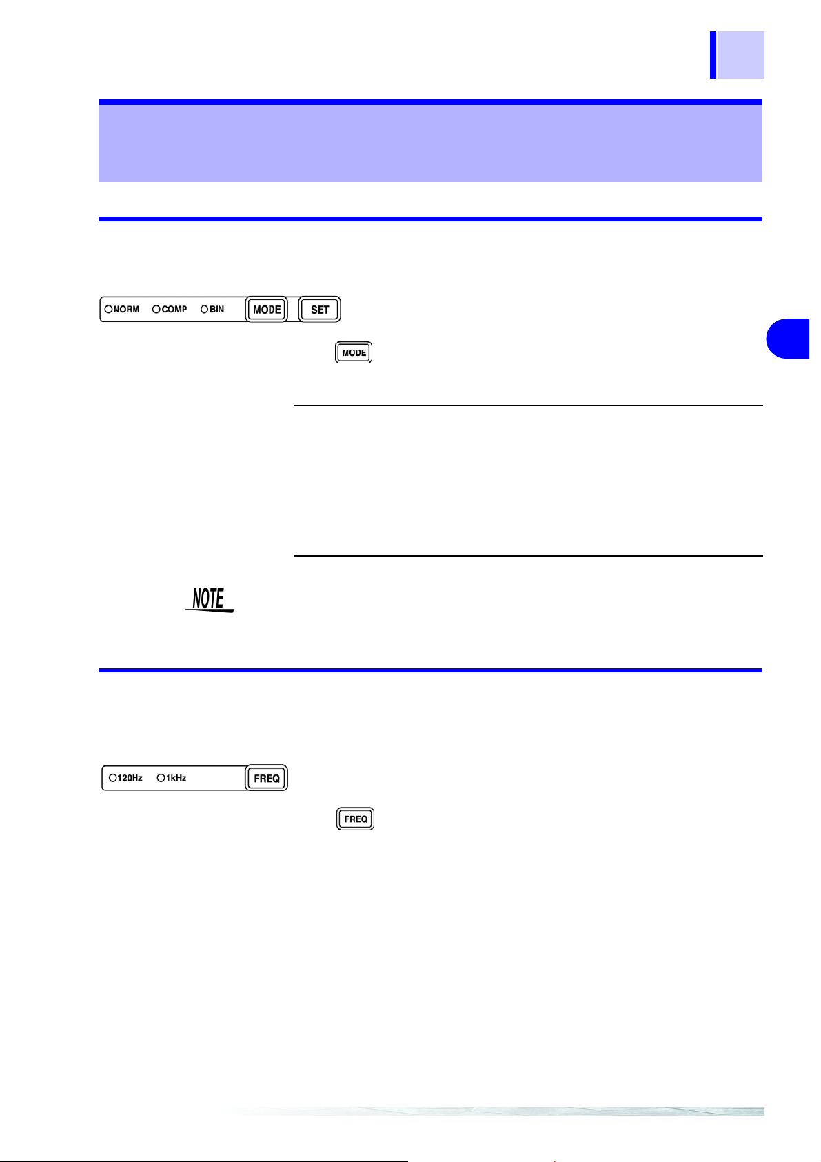
3.3.1 Measurement Mode
Select a measurement mode.
25
Mode:
Press to change the mode.
The selected item is indicated by the lit LED lamp.
NORM
COMP
BIN
(Model 3504
only)
The measurement conditions cannot be changed in comparator mode
and BIN mode. Set them in normal measurement mode.
NORM, COMP, BIN
Select this when using normal measurement mode.
Select this when using comparator measurement mode.
Select this when using BIN measurement
mode.
3.3.2 Measurement Frequency
Set the measurement frequency.
Set a frequency appropriate for the sample to be measured.
3
_________
4.1 (page 41)
4.2 (page 50)
Measurement frequency: 120 Hz, 1 kHz
Press to change the mode.
The selected item is indicated by the lit LED lamp.
Page 32

26
3.3 Setting the Measurement Conditions (Required Settings)
3.3.3 Measurement Signal Level
A voltage of ±12 V is generated at the L
L
terminals are in an open state.
CUR
Set the measurement signal level.
terminal when the L
CUR
POT
and
Set a signal level appropriate for the sample to be measured.
Measurement signal lev el : 500 mV, 1 V
Press to change the mode.
The selected item is indicated by the lit LED lamp.
500mV
1V
When the set voltage is appl ied to bot h sides of the sample , the CV indicator
lights up. The CV indicator does not light up when the applied voltage is lower
than the set voltage. In such a case, the EXT.I/O outputs a CV-ERR signal.
Constant-voltage measurement can be performed within the
range of 0.94 pF up to 170 μF (1 kHz) or 9.4 pF up to 1.45
mF (120 Hz).
Constant-voltage measurement can be performed within the
range of 0.94 pF up to 70 μF (1 kHz) or 9.4 pF up to 700 μF
(120 Hz).
Range
No.
1 200 pF 20 pF
2 2 nF 200 pF
3 20 nF 2 nF
4 200 nF 20 nF
52 μF 200 nF
6 20 μF 2 μF
7200 μF20 μF
8
1.45 mF (
9 2 mF 200 μF Open terminal
10 20 mF 2 mF
• In some s amples, the value may vary dependi ng on the measurementsignal level.
• Constant v oltage measurement may not be possibl e if the value of the
contact resistance between t he measurement terminals and the sample
is high. When thi s is t he ca se , “ – – – – – – ” app ears on the MAIN display
area, CV LED goes out, and a CV-ERR
120 Hz 1 kHz
700 μF (when 1 V)
when 500mV)
170 μF (
70 μF (when 1 V)
when 500mV)
signal is output from EXT.I/O.
Measurement
Voltage Mode
Constant voltage
mode
voltage mode
Output resistance
of 5 Ω
Page 33

3.3 Setting the Measurement Conditions (Required Settings)
3.3.4 Measurement Speed
Set the measurement speed.
27
Measurement speed:
Press to change the mode.
The selected item is indicated by the lit LED lamp.
FAST
NORM
SLOW
The lower the measurement speed, the higher the measurement
accuracy becomes.
Measurement speed
Measurement frequency FAST NORM SLOW
120 Hz 10 ms 37.5 ms 146 ms
1 kHz 2.0 ms 5.5 ms 29.5 ms
(Allowance: ±5%±0.5 ms)
The measurement ti me va ries d epe ndi ng on s uch factors as the ope n/s hor t
circuit compensation ON/OFF and the comparator ON/ OFF.
FAST, NORM, SLOW
Measures at high speed.
Measures at normal speed.
Measures at low speed, but provides improved measure-
ment accuracy.
3
3.3.5 Equivalent Circuit Mode
You may set an equivalent circuit mode (SER/ PAR).
Automatic selection is also possible.
"Equivalent Circuit Mode" (page 28)
Equivalent circuit mode: AUTO, SER, PAR
Press to change the mode.
The selected item is indicated by the lit LED lamp.
AUTO
SER
PAR
The series equivalent circuit mode or parallel equivalent circuit
mode is automatically selected according to the measurement
range.
Range No. Automatically selected mode
6 to 10 Series equivalent circuit
1 to 5 Parallel equivalent circuit
Series equivalent circuit mode
Parallel equivalent circuit mode
Page 34

28
3.3 Setting the Measurement Conditions (Required Settings)
Equivalent Circuit
Mode
The 3504 (3504-10) u nit analyses the measurement s ample in terms of an
equivalent circu it constru ction c omposed of a p ure capaci tive com pon ent (C)
and a pure resistive compone nt (R), and calcul ates as though these components were connected in ser ies, or alterna tivel y conn ect ed in parallel. Therefore, it is poss ib le f or the us er t o se lect ei t h er a ser i es -e qu iv al e nt ci rc ui t mo de
or a parallel-equiv alent circuit mode f or this conceptual connection together
of these C and R components.
Normally, the parallel-equivalent circuit mode is used for a small capacitance
(high-impedance components) because a small capacitance is a major cause
of parallel resistance loss. While the series-equivalent circuit mode is used for
a large capacitance (low-impedance components) because a large capacitance is a major cause of ser ies resistance loss from the resistive parts of
lead wires, etc.
Series-equivalent circuit
Parallel-equivalent circuit
The measuremen t errors are likely to be larg e if the equi valent c ircuit se tting
is configured inco rrectly. If the parallel-equivalent circuit is use d to measure,
for example, an electrolytic capacitor with a large D (low Q [quality factor]
the measurement valu es will differ from those when a series-equ ivalent circuit is used for measurement. The table below shows an example of the measurement values obtained using a parallel-equivalent circuit and a seriesequivalent circuit when D is altered for a capacitor for which the capacitance
is the same.
3504 (3504-10) displayed value
D Cs Cp
0C’ C’
0.1 1.005C’ 0.995C’
0.5 1.118C’ 0.8944C’
C' : Static capacitance (nominal value)
Cs: Static capacitance in series-equivalent circuit mode
Cp: Static capacitance in parallel-equivalent circuit mode
D : Dissipation factor
Therefore it is neces sar y for t he us er cle arly to u nderstand th e se ttin g of t his
measurement mode, in order properly to assess measurement samples.
*1
),
*1:
Measure of reactance purity.
Page 35

3.3 Setting the Measurement Conditions (Required Settings)
3.3.6 Measurement Range
Select a measurement range. Automatic selection is also possible.
29
Measurement Range:
Press to change the mode.
The selected item is indicated by the lit LED lamp.
AUTO
(Auto range)
HOLD
(
Hold range
)
AUTO, HOLD
The optimal measurement range is selected automatically.
This is useful for the measurement of unknown samples.
However, measurement takes longer.
The measurement range is fixed, and may only be altered
manually.
Take measurements in the same range regardless of the
value of the sample. This is useful for high-speed measurement.
Changing the range:
When the range is changed, the decimal point and unit in
the measurement value display area change. The range
number is displayed in the SUB display area.
Measurement ranges and display ranges
3
Range
No.
1 009.400 pF to 200.000pF 00.9400 pF to 20.0000 pF
2 0.09400 nF to 2.00000nF 009.400 pF to 200.000 pF
3 00.9400 nF to 20.0000nF 0.09400 nF to 2.00000 nF
4 009.400 nF to 200.000nF 00.9400 nF to 20.0000 nF
5 0.09400 μF to 2.00000 μF 009.400 nF to 200.000 nF
6 00.9400 μF to 20.0000 μF 0.09400 μF to 2.00000 μF
7 009.400 μF to 200.000 μF 00.9400 μF to 20.0000 μF
8 0.09400 mF to 0.70000 mF (when 1 V)
9 0.13500 mF to 2.00000 mF 016.000 μF to 200.000 μF
10 01.3500 mF to 20.0000 mF 0.16000 mF to 2.00000 mF
Guaranteed Accuracy Range of C (when D ≤ 0.1)
120 Hz 1 kHz
009.400 μF to 070.000 μF (when 1 V)
1.45000 mF (when 500 mV)
170.000 μF (when 500 mV)
Page 36

30
e
e
e
Over flow:
3.3 Setting the Measurement Conditions (Required Settings)
• If the me asurement v alues disp laye d on the unit ar e outside of the guaranteed accuracy range, the HOLD LED flashes.
• If the values are outside of the measurement va lue range, the following
may be displayed.
MAIN Display Area
Under flow:
C is smaller than th
measurement rang
Over flow:
C is larger than the
measurement rang
SUB Display Area
D is larger than the
measurement
range
• Do not co nnect a low-impedance compon ent with, for example, a static
capacitance larger than the Range 8 guaranteed accuracy range for a
prolonged period of time while the unit is in a Range 8 HOLD state.
If a low-impeda nce compone nt is c onnected for at leas t ten minu tes, the
“i-ovEr Error” i ndication flashes in the MAIN di splay area and measurement stops. To clear the error, open the measurement terminals and then
press .
Page 37

3.4 Measurement Conditions (Optional Settings)
3.4 Measurement Conditions (Optional Settings)
3.4.1 Open Circuit Compensation • Short Circuit Compensation
Open circuit compensation and short circuit compensation enable you to
reduce the effect of impedance remaining in parts such as the probe or fixture
and improv e measurement accuracy.
There are two ways of performing open circuit compensation and short circuit
compensation.
• All Compensation
This performs compens ation at all frequencies (120 Hz and 1 kHz). Thi s
can be performed from the front panel or via a PC.
• Spot Compensation
This performs compe nsation at the frequency currently set. Perform this
from a PC through the interface.
"Setting and Query of Open Circuit Compensation Function" (page 145) and "Set-
ting and Query of Short Circuit Compensation Function" (page 148) of “7.9, "Message Reference".
31
3
• The measurem ent accuracy values defin ed in the specifications are for
when open circuit compensati on and short cir cuit com pensation are performed.
• Be sure to perform compensat ion again after r eplacing the probe or fixture. Yo u will be unable to obtain correc t values if measurement is pe rformed in the compensation state prior to replacement.
• The open circuit compensation range of impedance is 1 kΩ or more.
However, if the values are not sufficiently hi gh compared to the impedance of the sample, t he measur ement errors wi ll be large r and meas urement may become no longer possible.
• The short circuit compensation range of impedance is less than 1 kΩ.
However, if the values are not sufficiently low compared to the impedance
of the sample, the measur ement errors will be larger and me asurement
may become no longer possible.
Page 38

32
3.4 Measurement Conditions (Optional Settings)
Performing Open Circuit Compensation, Short Circuit Compensation
1. In normal measurement mode, press .
The state becomes as follows.
• The OPEN LED flashes.
• The “oPEn SEt” indication is displayed and the “SEt” indication flashes in
the MAIN display area.
If you do not want to perform open circuit compensation, press to
proceed to configuring the short circuit compensation settings. (The
SHORT LED flashes and the “Short SEt” indication is displayed and the
“SEt” indication flashes in the MAIN display area.) Proceed to Step
(page 33)
.
2. Set an open state between the HIGH and LOW terminals of the probe or
fixture connected to the measurement terminals.
4.
• When perfo rming compensation, the placement of th ings like the probe
and the distances b etween terminals must be as s imilar as possible to
the state when performing measurement.
• If compensation is being affected by external noise, use the shielding process.
For details on the shielding process, refer to 6.2 "Measurement of High Imped-
ance Components" (p. 87).
3. Press .
Incorporate the open circuit compensation values. (AL L Compensation)
• The OPEN LED flashes.
• The “o PEn AdJuSt” indication is displayed and the “AdJuSt” indication
flashes in the MAIN display area.
End of Compensati on:
When compensation ends, the state becomes as follows.
• A beep tone sou nds onc e and the “oPEn End” indi cation i s disp layed i n
the MAIN display area for one second.
• The OPEN LED flashes.
• The SHORT LED flashes.
• The “Short SEt” indication is displayed and the “SEt” indication flashes in
the MAIN display area.
Compensation Error:
If there was a compensation error, the state becomes as follows.
• A warning beep tone sounds
• The “oPEn Error” indication is displayed in the MAIN display area.
Compensation stops.
Page 39

3.4 Measurement Conditions (Optional Settings)
33
What if there is an
error?
4. Use a shorting bar to create a short circuit state between the HIGH ter-
• If is pressed, the unit enters sh ort circu it comp ensat ion inc orpora te
mode. (Proceed to Step 4. (page 33).) (T he settings for op en circuit compensation remain the same as last time.)
• Are the measu rement terminals open? O pen the measurement termin als
and then perform compensation again.
• If there is a compensation error even when the measurement terminals are
open, external noise may be affecting com pensation or the unit, probe, or
fixture may be ma lfunctioning. Use the s hielding process, su bmit the unit
or fixture for repairs, or replac e the probe w ith a new o ne. ( The p ro be c annot be repaired.)
6.2 "Measurement of High Impedance Components" (p. 87)
3
minal and LOW terminal of the probe or fixture connected to the measurement terminals.
Use a shorting bar with as low an impedance as possible.
• When performing compensation, the placement of things like the probe
and fixture and the dis tances between terminals must be as similar as
possible to the state when performing measurement.
• If you do not want to perform short circuit compensation, press to
return to normal measurement mode.
5. Press .
Incorporate the short circuit compensation values. (ALL Compensation)
• The SHORT LED flashes.
• The “Short A dJuSt” indic ation is displayed and the “AdJuSt” indication
flashes in the MAIN display area.
End of Compensation:
When compensation ends, the state becomes as follows.
• A beep tone sounds once
• The “Short En d” ind ication i s displ ayed i n the MAI N display area fo r one
second.
• The SHORT LED flashes.
The unit returns to normal measurement mode.
Compensation Error:
If there was a compensat ion error, the state becomes as follows.
• A warning beep tone sounds
• The “Short Error” indication is displayed in the MAIN display area.
Compensation stops.
Page 40

34
3.4 Measurement Conditions (Optional Settings)
What if there is an
error?
• If is pressed, the unit returns to normal measurem ent mode. (The
settings for short circuit compensation remain the same as last time.)
• Are the measur ement terminals in a short circuit state? S hort circuit the
measurement terminals and then perform compensation again.
• If there is a compensation error even when the measurement terminals are
short circuited, the unit, pr obe, or fixture may be malfunctioni ng. Use the
shielding process, submit the unit or fixture for repairs, or replace the probe
with a new one. (The probe cannot be repaired.)
Canceling Open Circuit Compensation and Closed Circuit Compensation
1. In normal mode, press for at least two seconds while op en circ uit
compensation and closed circuit compensation are in an ON state.
The state becomes as follows.
• The OPEN LED flashes.
• The “oP En oFF” indic ation is display ed and the “o FF” indication fl ashes
in the MAIN display area.
* State when the OPEN or SHORT LED is flashing.
• While open circuit compensation and closed c ircuit compens ation are i n
an OFF state, the unit w ill not enter cancel m ode even if you press and
hold for at least two seconds.
• If only short circuit compensation is in an ON state, the unit enters short
circuit compensation cancel mode. (Proceed to Step 3. (page 34)).
2. Press .
Open circuit compensation is set to OFF and the state becomes as follows.
• The OPEN LED goes out.
• The “oPEn CAnSEL” indication lights up in the MAIN display area for
one second.
• The SHORT LED flashes.
• The “S hort oFF” i ndication is displayed and the “o FF” indicat ion flashes
in the MAIN display area.
• If you do not want to cancel open circuit compensation, press to
enter short circuit compen satio n canc el mode . (Proceed to Step 3. (page
34).)
• If sho rt compensat ion mode i s OFF, the unit retu rns to no rmal measurement mode.
3. Press .
Page 41

35
3.4 Measurement Conditions (Optional Settings)
Short circuit compensation is set to OFF and the state becomes as follows.
• The SHORT LED goes out.
• The “Short CAnSEL” indication lights up in the MAIN display area for one
second.
The unit returns to normal measurement mode.
If you do not want to cancel short circuit co mpensatio n, press to return
to normal measurement mode
3
Page 42

36
3.4 Measurement Conditions (Optional Settings)
3.4.2 Load Compensation
Load compensation allows for the calculation of the compensation rate by
measuring a standard sample with known measurement values and compensating the measurement values .
This function c an be used for the following.
• When using multiple 3504 (3504-10) units, reduce the measurement errors
of individual 3504 (3504-10) units and match the measurement values.
• Match the meas urement values of the 3504 (3504- 10) unit to thos e of the
reference measure device.
The conditions tha t are currently set (frequency, level, range, equivalent circuit mode, open circuit compensation, and short circuit compensation) are
used as the measur ement conditions for load compensation. Changing the
measurement conditi ons while load compensation i n enabled results in load
compensation being disabled. (When this happens , the OFF LED of LOAD
flashes.)
If, however, the measurement cond iti on s ar e retur ne d t o w hat the y wer e du ring load compensation, then load compensation is resumed. (The ON LED of
LOAD lights up.)
The compensation rate is determined by first calculating the impedance Z
and phase angle θ from the reference values of the measurement conditions,
C, and D and the actua l measurement values and then using the following
formula for the calculation.
Z compensation rate = (Z reference value)/(Z actual value)
θ compensation rate = (θ reference value) − (θ actual value)
For the actual values of Z and θ, compe ns ation is per formed u sing the abov e
compensation rate and then C a nd D are cal culated fr om Z and θ after compensation.
When open circuit compensation and short circuit compensation are
enabled, load compe nsation pe rforms com pensatio n for Z and θ after open
circuit compensation and short circuit compensation are finished.
Perform open circuit co mpensation and short circuit compensati on before
you incorporate load compensation data.
Performing Load Compensation
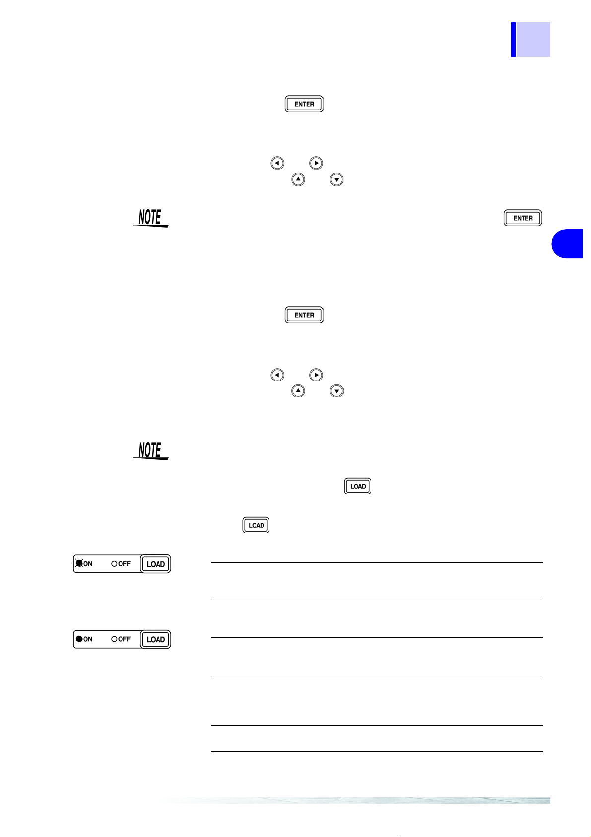
1. In normal measurement mode, press .
The state becomes as follows.
• The ON LED flashes.
Light up
• The “LoAd SEt” indication is displayed and the “SEt” indication flashes in
the MAIN display area.
• The COUNT and REF LEDs light up in the SUB display area.
• The reference values for C and D are displayed in the SUB display area.
• The LED on the far left of the C reference value flashes.
If you want to ex it the reference value input s creen and return to normal
measurement mode, press for at least two seconds.
Page 43
37
3.4 Measurement Conditions (Optional Settings)
2. Use the numeric keypad or arr ow keys to enter a reference valu e for C
and then press .
Use the numeric keypad to enter a number. (If you enter a number, each digit
moves one place to the right.) Settable Range: 1 to 999999
You can use and to move to the digit you want to change.
You can also use and to change the number set for a digit.
• If you do not want to ch ange the reference value of C, press
without changing the number. The reference va lue input screen for D is
displayed.
• Set count val ues for the reference values. The reference values at the
time of shipment are 100000 for C and 0 for D.
3. Use the numeric keypad or arr ow keys to enter a reference valu e for D
and then press .
3
Use the numeric keypad to enter a number. (If you enter a number, each digit
moves one place to the right.) Settable Range: 0 to 199000
You can use and to move to the digit you want to change.
You can also use and to change the number set for a digit.
The unit returns to the state of Step 1. (page 36).
• If there is no need to change the reference value of D, proceed to Step 4.
(page 37) without changing the number.
• If you want to exit the refer ence value input screen and return to normal
measurement mode, press for at least two seconds.
4. Press .
Incorporate the load compensation values.
• The ON LED flas hes.
• The “LoAd AdJuSt” indication is displayed and the “AdJuSt” indication flashes in the MAIN display area.
End of Compensation:
When compensation ends normally, the state becomes as follows.
• A beep tone sounds once.
• The “LoAd End” indication lights up in the MAIN display for one second.
• The ON LED lights up.
The unit returns to normal measurement mode.
Compensation Error:
If there was a compensat ion error, the state becomes as follows.
• A warning beep tone sounds
• The “LoAd Error” indication lights up in the MAIN display area.
Compensation stops.
Page 44
38
3.4 Measurement Conditions (Optional Settings)
The conditions that ar e cu rre n tly s et (f re que nc y, level, range, equivalent ci rcuit mode, open circu it compensation, and short circ uit compensation) are
used as the measur ement condit ions for load compensati on. Changing th e
measurement conditions while load compensation in enabled results in load
compensation being di sabled. (When th is happens, th e OFF LED of LOAD
flashes.)
If, however, the measurement conditions are returned to what they were
during load compe nsation, then load compensation is resumed. (The ON
LED of LOAD lights up.)
What if there is an
error?
• To return to normal measurement mode, press .
• If the value is o utside the mea surement r ange (under flow or over flow) or
the constant voltage is not output (C V erro r), a com pensa tion erro r is generated. Set an appropriate range and then perform compensation again.
Canceling Load Compensation
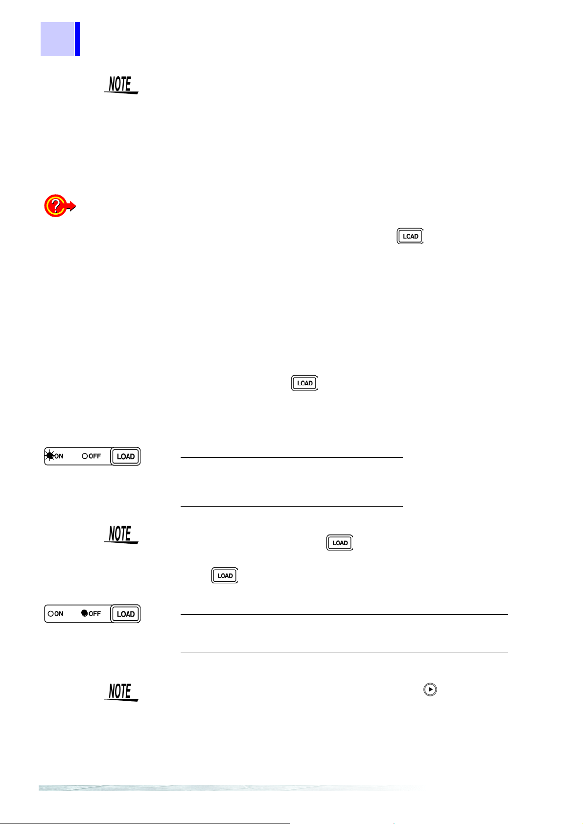
1. In normal mode, press for at least two seconds while load com-
pensation is in an ON state.
* State when the ON LED of LOAD is lit.
The state becomes as follows.
• The ON LED flashes.
• The “LoA d oFF” indication is dis played and the
“oFF” indication flashes in the MAIN display
area.
While load compensati on is in an OFF state, the unit will not enter cance l
mode even if you press and hold for at least two seconds.
2. Press .
Load compensation is set to OFF and the state becomes as follows.
• The “LoAd CAnSEL” indication lights up in the MAIN display area for one
second.
• The OFF LED lights up.
The unit returns to normal measurement mode.
If you do not want to cancel lo ad compensation , press to enter normal
measurement mode.
Page 45

3.4.3 Trigger Signal
The internal trigger or the external trigger can be set.
39
3.4 Measurement Conditions (Optional Settings)
When inputting the
trigger signal through the
interface
Trigger signal:
Press to change the mode.
INT
(Internal trigger
mode)
EXT
(External trigger mode)
Measurement starts when a "*TRG" comman d is received through the interface.
INT, EXT
• Continuous measurement is performed while automatically generating an internal trigger signal.
The INT LED flashes.
•
• A trigger signal is input from the outside either manually or automatically.
• The EXT LED lights up.
• Manual setting:
Press to perform measurement once.
• Measurement is performed with a trigger from the
EXT I/O connector TRIG terminal.
For details on i nputting the trigger signal through the interface, refer to
"Sampling Request" (page 130) of 7.9, "Message Reference".
3
When inputting the
trigger signal through the
EXT I/O connector
When a negative-log ic pulse signal is input to TRIG (pin 1) of the EXT I/O
connector on the rear panel, one measurement operation is performed.
6.1 "Measurement Using EXT I/O" (p. 81)
Page 46

40
3.4 Measurement Conditions (Optional Settings)
Page 47

4.1 Comparator Function
Application
Functions Chapter 4
4.1 Comparator Function
This function enables you to set the upper limit and lower limit values for each
of C and D, and then ind icates the judgment re sult with HI, IN, or LO in t he
comparator judgment result display area.
The judgment result enables you to determine whether the sample has
passed or failed.
41
4
The corresponding si gnal is also output from the EXT.I/O conn ector on the
rear of the unit.
There are two judgment modes for comparator measurement: the count
value setting and deviation percent (
• Count Value Setting
Set count values for the uppe r limit and lowe r limit value s of the measurement parameters. The values of measurement parameters are display ed
unchanged as the measurement values.
• Deviation Percent (Δ%) Setting
•Enter reference values and then set percentages corresponding to the
reference values as the upper limit and lower limit values. The differences from referenc e values (C:
surement values.
•When
If the power is turned off while the unit is in comparator me asurement mod e,
the unit will be in comparator measurement mode when the unit is turned
back on again.
Δ% is set, the displayed results are calculated with C as Δ
%=(measurement v alue – referen ce v alue)/| referenc e va lue| × 100 a nd
D as
Δ=(measurement value – reference value).
Δ%) setting.
Δ%, D: Δ) are displayed as th e mea-
• Set the upper limit and lower limi t values o f any param eter that does not
require a comparator judg ment to be made to OFF s o that judgm ent will
not be performed.
• The measurem ent conditions for normal meas urement mode are inherited as is for the measu rement conditions when the comparator is e xecuted. However, the AUTO range is automatically set to the HOLD range.
Page 48

42
4.1 Comparator Function
Setting Judgment Mode
First, set the judgment mode. (Sele ct the count value setting or the deviatio n
percent [
The judgment modes are the same for both the comparator and BIN.
1. In normal measurement mode, press .
The menu items are displ ayed at the to p of the MAIN displ ay area and th e
setting items are displayed at the bottom of the MAIN display ar ea.
• This setting cannot be changed in comparator mode and BIN mode.
• Use and to move through the menu items as follows.
Δ%] setting.)
“LoAd_A(C/h)” ÅÆ “SAVE” ÅÆ “Ld_tYP” ÅÆ “JudGE ” ÅÆ “bEEP_ J”
ÅÆ “bEEP_K” ÅÆ “CLK” (only for special specifica tions) ÅÆ “SYnC”
ÅÆ “IF.GPib(rS/Prnt)” ÅÆ “LoAd_A(C/h)” ÅÆ …
2. Use or to select the “JudGE” menu item. ( Judgment mode set-
ting screen)
The setting items are as follows.
“Count”: Count setting
“d-PAr”: Deviation percent (
Δ%) setting
3. Use or to select a setting item.
Pressing or switches between “Count” ÅÆ “d-PAr.”
4. Press .
The judgment mode is confirmed
After confirmation, “bEEP_J” is displayed at the top of the MAIN display area.
(Beep setting screen for judgment result)
The judgment mode is not confirmed unless is pressed.
5. Press .
The unit returns to normal measurement mode.
Page 49

4.1 Comparator Function
• Num eric
s
• Num eric
s
• Num eric
s
• Num eric
s
• Num eric
s
• Num eric
s
Setting the Upper Limit and Lower Limit Values for the Comparator
Setting Workflow
43
Normal measurement
1
mode
Comparator measurem ent
2
3
mode
C setting
Reference value setting for
4
(Only for the Δ% setting)
C
Upper limit and lower limit
5
value settings for C
keypad
• Arrow key
keypad
• Arrow key
Switch to comparator measurement mode.
The range is automatically set to HOLD.
Switch to the setting mode for the upper limit
and lower limit values.
Confirm C.
Move to the next setting.
Set the reference value for C.
Move to the next setting.
Set the upper limit value for C.
Confirm the upper limit value.
4
6
D setting
Reference value setting for
7
(Only for the Δ% setting)
D
Upper limit and lower limit
8
value settings for D
keypad
• Arrow key
keypad
• Arrow key
keypad
• Arrow key
keypad
• Arrow key
Set the lower limit value for C.
Confirm the lower limit valu e.
Move to the next setting.
Select D.
Confirm D.
Move to the next setting.
Set the reference value for D.
Move to the next setting.
Set the upper limit value for D.
Confirm the upper limit value.
Set the lower limit value for D.
Confirm the lower limit valu e.
Page 50

44
4.1 Comparator Function
Setting Procedure
1. Use to switch to the comparator measurement mode and press
.
The state becomes as follows.
• The COMP LED flashes.
• The “C” indication at the top of the SUB display area flashes.
• For the
• For the count setting: The COUNT, HI, and LO LEDs light up.
• When the “C” or “D” indication is flashing at the top of the SUB display
area, you can configur e the setti ngs in any order if yo u us e or to
Δ% setting: The Δ% and REF LEDs light up.
(Only for the
(Only for the
2.
Δ% setting)
3. Use the numeric keypad or arrow keys to enter a reference value for
Δ% setting)
change the setting mode as follows and then press .
C Reference Value (only for the
Lower Lim it Values ÅÆ D Reference Value (only for the
D Upper Limit and Lower Limit Values ÅÆ C Reference Value …
• For the count setting, proceed to Step 5. (page 45).
Press to confirm C.
The unit switches to th e s ett ing mo de for th e C refer en ce va lu e a nd t he state
becomes as follows.
• The “C” indication at the top of the SUB display area flashes.
• The LED on the far left of the C reference value flashes.
• The C reference val ue index number at the bottom of the SUB dis play
area lights up.
C.
Use the numeric keypad to enter a number. (If you enter a number, each digit
moves one place to the right.) Settable Range: 1 to 999999
You can use and to move to the digit you want to change.
You can also use and to change the number set for a digit.
Set a count value for the reference value. At the time of shipment, the
reference value for C is 100000.
Δ% setting) ÅÆ C Upper Limit and
Δ% setting) ÅÆ
(Only for the
4.
Δ% setting)
Press to confirm the C reference value.
The state becomes as follows.
• The “C” indication at the top of the SUB display area flashes.
• The HI and LO LEDs light up.
The reference value entered this time is not confirmed unless
is pressed. The re ference value used last time becomes valid.
Page 51

Light up
45
4.1 Comparator Function
5. Press to confirm C.
The unit switches to the setting mode for the C upper limi t value and the
state becomes as follows.
• The HI and LO LEDs light up.
• The “C” indication at the top of the SUB display area lights up.
• The LED on the far left of the C upper limit value of the SUB display area
flashes.
6. Use the numeric keypad or arrow keys to enter an upper limit val ue for
C and then press .
Lights up
The C upper limit value is confirmed and the unit switches to the setting
mode for the C lower limit value.The state becomes as follows.
The LED on the far left of the C lower limit value of the SUB display area
flashes.
The settable ranges for the C upper limit and lower limit values are as follows.
• For the
• For the count setting: OFF/0 to 999999
Δ% setting: OFF/−999.99 to 999.99
7. Use the numeric keypad or arrow keys to enter a lower limit value for
C and then press .
(Only for the Δ% setting)
The C lower limit value is confirmed and the state becomes as follows.
• The “d” indication at the top of the SUB display area flashes.
• The REF LED lights up.
4
For the count sett ing, proceed to Step 10. (page 46).
Page 52

46
4.1 Comparator Function
8. Press to confirm “d”.
(Only for the
(Only for the
Δ% setting)
The unit switches to the setting mode for the D reference value and the
state becomes as follows.
• The “d” indication at the top of the SUB display area lights up.
• The LED on the far left of the D reference value flashes.
9. Use the numeric keyp ad or arrow keys to ent er a ref eren ce value f or D
and then press .
Δ% setting)
The D reference value is confirmed and the state becomes as follows.
• The “d” indication at the top of the SUB display area flashes.
• The HI and LO LEDs light up.
Settable range: 0 to 199000
Set a count value for the reference value. At the time of shipment, the
reference value for D is 0.
Light up
10. Press to confirm “d”.
The unit switches to the setting mode for the D upper limit value and the
state becomes as follows.
• The HI and LO LEDs light up.
• The “d” indication at the top of the SUB display area lights up.
• The LED on the far left of the D upper limit value of the SUB display area
flashes.
11. Use the numeric keypad or arrow keys to enter an upper limit value for
D and then press .
The D upper limit value is confirmed and the unit switches to the setting mode
for the D lower limit value.
The state becomes as follows.
The LED on the far left of the D lower limit value of the SUB display area
flashes.
The settable ranges for the D upper limit and lower limit values are as follows.
• For the Δ% setting: OFF/−199000 to 199000
• For the count setting: OFF/0 to 199000
Page 53

47
4.1 Comparator Function
12. Use the numeric keypad or arrow keys to enter a lower limit value for
D and then press .
The D lower limit value is confirmed and the state becomes as follows.
• The COMP LED flashes.
• The “C” indication at the top of the SUB display area flashes.
• For the
• For the count setting: The COUNT, HI, and LO LEDs light up.
Δ% setting: The Δ% and REF LEDs light up.
13. Press .
4
The unit switches to the comparator measurement mode. (The COMP
LED lights up.)
• The upper li mit and lo wer limit v alues for the count setting an d the refe rence value for the
pendent of the measureme nt conditions. If the measurement c onditions
differ, the absolute values that signify the count values change.
• The measurement conditions for normal measurement mode are used for
the comparator measurem ent mode. Set the measurement conditions to
use for comparator measu rement mode whil e the unit is in normal measurement mode.
• The comparator judgment is performed in the following order.
1.When the measurement value is “– – – – – –”: HI is displayed
When the measurement value is “OF”: HI is displayed
When the measurement value is “UF”: LO is displayed
2.The unit judges whether or not the measurement value is large r than
the lower limit value a nd then displays LO if it is not.
3.The unit judges whether or not the meas ureme nt valu e is smalle r than
the upper limit value and then displays HI if it is not.
4.IN is displayed if the conditions of 2 and 3 are satisfied.
• The large/small judgment for th e upper limit and l ower limit valu es is not
performed. An error i s no t g ener at ed if the upper limit and l ower li mit v alues are set in reverse, but the judgment cannot be performed properly.
Δ% setting become display count values that are inde-
Page 54

48
4.1 Comparator Function
Setting the Upper Limit and Lower Limit Values to OFF
1. When entering the upper limit and lower limit values, use to move
left until the far left digit flashes and then press and hold for at
least two seconds or use to move right until the far right digit
flashes and then press and hold for at least two seconds.
The display changes t o “– – – – – –” and OFF is set.
2. Press to confirm the OFF setting.
3. Press .
The unit switches to comparator measurement mode. (The COMP LED lights
up)
Canceling Comparator Measurement Mode
In comparator measurement mode, press twice.
The measurement mode LEDs light in the order of COMP Æ BIN (only for
3504) Æ NORM, and then the unit switches to normal measurement mode.
Performing Comparator Measurement
Follow the procedure below to perform comparator measurement.
In normal measurement mode, press
The state becomes as follows (comparator measurement mode).
• The COMP LED lights up.
• For the deviation percent setting:
The
Δ% and REF or HI and LO LEDs light up.
The comparator setting state is displayed in the SUB display area.
• For the count setting:
COUNT, HI, and LO LEDs light up.
The comparator setting state is displayed in the SUB display area.
• You can use and to change the indications in the SUB display
area.
• C Reference Value (only for the
Lower Lim it Values ÅÆ D Reference Value (only for the
D Upper Limit and Lower Limit Values ÅÆ C Reference Value …
• The measurement range is automatically set to HOLD.
Δ% setting) ÅÆ C Upper Limit and
Δ% setting) ÅÆ
Page 55

4.1 Comparator Function
U
u
L
u
U
l
s
49
Displaying Judgment
Results
Each of the judgment results for C and D is displayed in the comparator judgment result display area.
The comparator judgment is not performed for parameters with the upper limit
and lower limit values set to OFF.
pper limit and
ower limit value
ettings
pper limit val-
e
ower limit vale
Measurement
range
Upper limit
Lower limit
Measurement value judgment
HI
IN
LO
Measurement value judgment
HI
Measurement
range
LO
When the measurement value is larger than the
upper limit value
When the measurement value is within the
range of the upper limit and lower limit values
When the measurement v alue is smaller than
the lower limit value
When the measurement value is above the
measurement range (OVER FLOW)
When the measuremen t value is below the
measurement range (UNDER FLOW)
4
Outputting Judgment
Results
• Output the judgmen t result for each of C and D (LO/IN/HI) and the AND
results for both jud gment resu lts (only whe n both para meters are IN) from
EXT.I/O.
6.1 "Measurement Using EXT I/O" (p. 81)
• The comparator judgment results (IN/NG) can be differentiated by beep
tones.
5.1 "Setting Beep Tones" (p. 73)
Except for the trigger setting, the measurement conditions cannot be
changed in comparator measurement mode.
Press to switch to normal measureme nt mode and then change the
measurement conditions.
Keys Enabled for
Comparator Mode
Key Function
Switches the measurement mode.
Switches to the sett ing modes for the upper limit a nd lower
limit values.
Switches the trigger setting to INT/EXT.
This key is only enabled whe n the tri gger sett ing is EXT. One
measurement is performed each time the key is pressed.
Menu items other than “JudGE,” “bEEP_J,” “CLK” (only for
special specifications), and “SynC” can be set.
For functions that cannot be set, the “– – – –” indication is displayed at the bottom of the MAIN display area.
(Set “JudGE,” “bEEP_J,” “CLK” (only for special specifications), and “SynC” in normal measurement mode.)
Changes the keylock function and cancels the remote state.
Page 56

50
4.2 BIN Measurement Function (Only for 3504)
4.2 BIN Measurement Function
(Only for 3504)
This function e nables you to set up t o 14 categories of uppe r limit and lower
limit values for C and one ca tego ry of upp er limit an d lowe r limi t va lue s for D,
and indicates the j udgment results in the BIN judgment resu lt display area.
The corresponding signa l is also output from the EXT.I/O connector on the
rear of the unit.
There are two judgment modes for BIN measurement: the count value setting
and deviation percent (
• Count Value Setting
Set count values for the upper limit and lower limit values of the measurement parameter. The measurement parameter values are displayed
unchanged as the measurement values.
• Deviation Percent (Δ%) Setting
Enter reference values and then set perce ntages co rres po ndi ng to th e r eference values for the upper l imit and lower limit values. The differences
from the reference values (C:
ment values.
Δ%) setting
Δ%, D: Δ) are displaye d as the measure-
If the power is tur ned off whil e th e u nit is i n B IN m easur em ent mo de, the unit
will be in BIN measurement mode when the unit is turned back on again.
• Set the upper limit and lower limit values of any BIN number that does not
require a BIN judgment to be made to OFF so that judgment will not be
performed.
• The meas urement conditions for norm al measurement mode are inherited as is for the measurement conditions when the BIN is executed.
However, the AUTO range is automatically set to the HOLD range.
Page 57

Setting Judgment Mode
First, set the judgment mode. (Select the count value setting or the deviation percent [
The judgment modes are the same for both the comparator and BIN.
1. In normal measurement mode, press .
The menu items ar e displayed at the top of the MAIN display area and the
setting items are displayed at the bottom of the MAIN display area.
• This setting cannot be changed in comparator mode and BIN mode.
• Use and to move through the menu items as follows.
51
4.2 BIN Measurement Function (Only for 3504)
Δ%] setting.)
“LoAd_A(C/h)” ÅÆ “S AV E” ÅÆ “Ld_tYP” ÅÆ “J udGE” ÅÆ “bEEP_J”
ÅÆ “bEEP_K” ÅÆ “CLK” (only for s pecial specificatio ns) ÅÆ “SYnC”
ÅÆ “IF.GPib(rS/Prnt)” ÅÆ “LoAd_A(C/h)” ÅÆ …
4
2. Use or to select the “JudGE” menu item. (J udgment mode s et-
ting screen)
The setting ite m s ar e as fol lo w s .
“Count”: Count setting
“d-PAr”: Deviation percent (
Δ%) setting
3. Use or to select a setting item.
Pressing or switches between “Count”
ÅÆ “d-P Ar.”
4. Press .
The judgment mode is confirmed
After confirmation, “bEEP_J” is displayed at the top of the MAIN display area.
(Beep setting screen for judgment result)
The judgment mode is not confirmed unles s is pressed.
5. Press .
The unit returns to normal measurement m ode.
Page 58
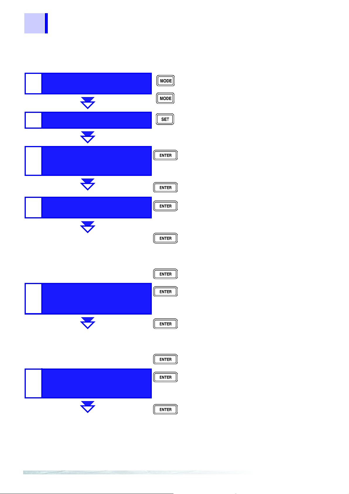
52
s
s
s
s
s
s
4.2 BIN Measurement Function (Only for 3504)
Setting the Upper Limit and Lower Limit Values for the BIN
Setting Workflow
Normal measurement
1
2
BIN measurement mode
mode
Reference value setting for
3
(Only for the Δ% setting)
C
Upper limit an d l ow er li mi t
4
value settings for BIN1
• Num eric
keypad
• Arrow key
• Num eric
keypad
• Arrow key
Switch to comparator measurement mode.
Switch to BIN measurement mode.
The range is automatically set to HOLD.
Switch to the setting mode for the upper limit
and lower limit values.
Confirm C.
Set the reference value for C.
Confirm the setting value.
Move to the next setting.
Confirm BIN1.
Set the upper limit value for BIN1.
Confirm the upper limit value .
Upper limit an d l ow er li mi t
value settings for BIN2 to
5
BIN14
Reference value setting for
6
(Only for the Δ% setting)
D
• Num eric
keypad
• Arrow key
• Num eric
keypad
• Arrow key
• Num eric
keypad
• Arrow key
• Num eric
keypad
• Arrow key
Set the lower limit value for BIN1.
Confirm the lower limit value.
Move to the next setting.
Confirm BIN2 to BIN14.
Set the upper limit values.
Confirm the upper limit value s.
Set the lower limit values.
Confirm the lower limit values.
Move to the next setting.
Confirm D.
Set the reference value for D.
Confirm the reference value.
Move to the next setting.
Page 59

4.2 BIN Measurement Function (Only for 3504)
s
s
53
Upper limit and lowe r li mit
7
8
value settings for D.
BIN measurement mode
Setting Procedure
1. Use to switch to the BIN measurement mode and press .
Confirm D.
• Numeric
keypad
• Arrow key
• Numeric
keypad
• Arrow key
The state becomes as follows.
• The BIN LED flashes.
• For the
The
The “C” indication at the top of the SUB display area flashes.
• For the count setting:
The COUNT, HI, and LO LEDs light up.
The “1” indication at the top of the SUB display area flashes.
Δ% setting:
Δ% and REF LEDs light up.
Set the upper limit value for D.
Confirm the upper limit value.
Set the lower limit value for D.
Confirm the lower limit value.
Move to the next setting.
Switch to BIN measurement mode.
4
(Only for the
2. Press to confirm “C”.
Δ% setting)
• When the “1 to 14,” “C ,” or “d” in dication is flashi ng at the top o f the SUB
display area, you can configure the settings in any order if you use or
to change the setting mode as follows and then pr ess .
C Reference Value (only for the
and Lower Limit Values ÅÆ D Reference Value (only for the
ÅÆ D Upper Limit and Lower Limit Values ÅÆ C Reference Value …
• For the count setting, proceed to Step 5. (page 54).
The unit switches to the setting mode for the C reference value and the
state becomes as follows.
• The “C” indication at the top of the SUB display area flashes.
• The LED on the far left of the C reference value flashes.
• The index number for the C reference value at the bottom of the SUB
display area lights up.
Δ% setting) ÅÆ BIN 1 to 14 Upper Limit
Δ% setting)
Page 60

54
4.2 BIN Measurement Function (Only for 3504)
(Only for the
3. Use the numeric keypad or arrow keys to enter a reference value for
Δ% setting)
4. Press to confirm the C reference value.
C.
Use the numeric keypad to enter a number. (If you enter a number, each digit
moves one place to the right.) Settable Range: 1 to 999999
You can use and to move to the digit you want to change.
You can also use and to change the number set for a digit.
Set a count value for the reference value. At the time of shipment, the
reference value for C is 100000.
(Only for the
Lights up
Δ% setting)
5. Press to confirm “1”.
The state becomes as follows.
• The HI and LO LEDs light up.
• The “1” indication at the top of the SUB display area flashes.
The reference value entered this time is not confirmed unless
is pressed. The re ference value used last time becomes valid.
The unit swit ches to th e setting m ode for the BIN1 upper limit v alue and th e
state becomes as follows.
• The HI and LO LEDs light up.
• The “1” indication at the top of the SUB display area lights up.
• The LED on the far left of the BIN1 upper limit value of the SUB display
area flashes.
6. Use the numeric keypad or arr ow keys to ent er an upper limit val ue for
BIN1 and then press .
The BIN1 upper li mit value is conf irmed and the unit s witches to the se tting
mode for the BIN1 lower limit value.
The state becomes as follows.
The LED on the far left of the BIN1 lower limit value of the SUB display area
flashes.
The settable ranges for the C upper limit and lower limit values are as follows.
• For the
• For the count setting: OFF/0 to 999999
• At the time of shipme nt, the upp er limit and lower limit va lue s are OFF ( ”--
----”). If any key is pr essed, the LEDs on th e far le ft of the BIN uppe r and
lower values flash.
• The BI N upper limit and l ower limit values entered this tim e are not confirmed unless is pressed. T he BIN upper limit and lower limit
values used last time become valid.
Δ% setting: OFF/−999.99 to 999.99
Page 61

Lights up
55
4.2 BIN Measurement Function (Only for 3504)
7. Use the numeric keypad or arrow keys to enter a lower limit value for
BIN1 and then press .
The BIN1 lower li mit val ue is con fir med and t he st at e b eco mes as fol l ows.
The “2” indication at the top of the SUB display area flashes.
8. Press to confirm “2”.
The unit switch es to the setting mod e for the BIN2 upper li mit value an d the
state becomes as follows.
• The “2” indication at the top of the SUB display area lights up.
• The LED on the far left o f the BIN2 u pper limit value of the S UB displ ay
area flashes.
Set all the BIN upper limit and lower limit values in the same manner.
(Only for the Δ% setting)
After all t he BI N up per li mit a nd lo wer li mi t val ue s ha ve bee n se t, th e st a te
becomes as follows.
• The REF LED lights up.
• The “d” indication at the top of the SUB display area lights up.
4
(Only for the
(Only for the
For the count sett ing, proceed to Step 12. (page 56).
9. Press to confirm “d”.
Δ% setting)
The unit switches to the setting mode for the D reference value and the
state becomes as follows.
• The “d” indication at the top of the SUB display area lights up.
• The LED on the far left of the D reference value flashes.
10. Use the numeric keyp ad or arrow keys t o enter a r efe rence val ue for D
and then press .
Δ% setting)
The D reference value is confirmed and the state becomes as follows.
• The “d” indication at the top of the SUB display area flashes.
• The HI and LO LEDs light up.
Settable range: 0 to 199000
Set a count value for the reference value. At the time of shipment, the
reference value for D is 0.
Page 62

56
4.2 BIN Measurement Function (Only for 3504)
11. Press to confirm “d”.
The unit switches to the setting mode for the D upper limit value and the
state becomes as follows.
• The HI and LO LEDs light up.
• The “d” indication at the top of the SUB display area lights up.
• The LED on the far left of the D upper limit value of the SUB display area
flashes.
Light up
12. Use the numeric keypad or arr ow keys to enter an upper limit value for
D and then press .
The D upper limit value is confirmed and the unit switches to the setting
mode for the D lower li m it value. The state becomes as follows.
The LED on the far left of the D lower limit value of the SUB display area
flashes.
The settable ranges for the D upper limit and lower limit values are as follows
• For the
• For the count setting: OFF/0 to 199000
Δ% setting: OFF/−199000 to 199000
13. Use the numeric keypad or arrow keys to enter a lower limit value for
D and then press .
The D lower limit value is confirmed and the state becomes as f ollows.
• The BIN LED flashes.
• For the
The
The “C” indication at the top of the SUB display area flashes.
• For the count setting:
The COUNT, HI, and LO LEDs light up.
The “1” indication at the top of the SUB display area flashes.
Δ% setting:
Δ% and REF LEDs light up.
14. Press .
The unit switches to the BIN measurement mode. (The BIN LED lights up.)
Page 63
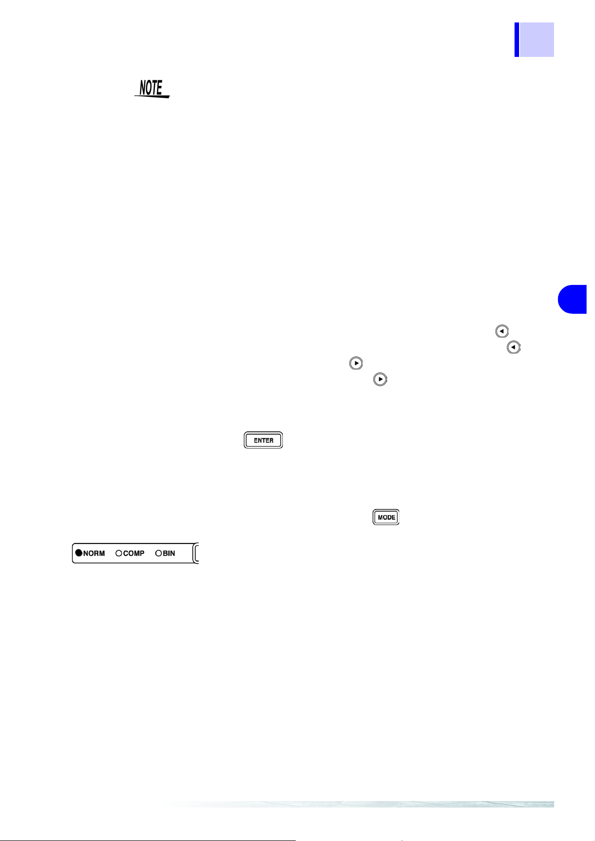
57
4.2 BIN Measurement Function (Only for 3504)
• The upper li mit and lo wer limit v alues for the count setting an d the refe rence value for the
pendent of the measureme nt conditions. If the measurement c onditions
differ, the absolute values that signify the count values change.
• The measurement conditions for normal measurement mode are used for
the BIN measurement mode. Set the measurement conditions to use for
BIN measurement mode while the unit is in normal measurement mode.
• Error judgment is not performed when the upp er limit and low er limit values are confirmed.
• Check the follo wing because judgment canno t be performed properly if
the upper limit and lower limit values are set incorrectly.
•Are the setting values within the display range of the measurement
range?
•Is the large/sm all relationship of the upper l imit and lower limit values
correct?
Δ% setting become display count values that are inde-
Setting the Upper Limit and Lower Limit Values to OFF
1. When entering the upper limit and lower limit values, use to move
left until the far left digit flashes and then press and hold for at
least two seconds or use to move right until the far right digit
flashes and then press and hold for at least two seconds.
The display changes to “– – – – – –” and OFF is set.
2. Press to confirm the OFF setting.
Canceling BIN Measurement Mode
In BIN measurement mode, press .
The measurement mode LE Ds light in the order of BIN Æ NORM, and th en
the unit switches to normal measurement mode.
4
Page 64

58
l-
e
it
l-
4.2 BIN Measurement Function (Only for 3504)
Performing BIN Measurement
Follow the procedure below to perform BIN measurement.
In normal measurement mode, press twice.
The state become s as follows (BIN measurement mode).
• The BIN LED lights up.
• For the deviation percent setting:
Δ% and REF or HI and LO LEDs light up.
The
The BIN setting state is displayed in the SUB display area.
• For the count setting:
COUNT, HI, and LO LEDs light up.
The BIN setting state is displayed in the SUB display area.
• You can use and to change the indications in the SUB display
area.
• C Refere nce Value (only for the
and Lower Limit Values ÅÆ D Reference Value (only for the
ÅÆ D Upper Limit and Lower Limit V alues ÅÆ Display OFF ÅÆ C Reference Value …
• If both the up per limi t and lower limit va lues ha ve not be set for C and D,
the BIN judgment automatically becomes OUT OF BINS.
• The measurement range is automatically set to HOLD.
Δ% setting) ÅÆ BIN1 to 14 Upper Limit
Δ% setting)
Displaying Judgment
Results
Each of the judgmen t results is displa yed in the BIN jud gment result di splay
area.
C
Upper limit
value
Lower limit
value
When the measurement
value is smaller t han the
lower limit value of D
Hi
Lo
OUT OF BINS
BIN1
D-NG D-NG
BIN2
…
BIN14
OUT OF BINS
Lo Hi
Lower limit value Upper limit value
When the measurement
value is larger than the upper limit value of D
When the measurement value is larger
than the upper limit va
ue of C
When the measurement value is within th
range of the upper lim
and lower limit values
of C
When the measurement value is smaller
than the lower limit va
ue of C
D
When the measuremen t value is
within the judgment range of the
upper limit and lower li mit valu es
of D
Page 65

4.2 BIN Measurement Function (Only for 3504)
59
Outputting Judgment
Results
Keys Enabled for
Comparator Mode
• Output the judgment result for BIN (BIN1 to 14, OUT OF BINS, and D-NG)
from EXT.I/O.
6.1 "Measurement Using EXT I/O" (p. 81)
• The BIN judgment results (IN/NG) can be differentiated by beep tones.
5.1 "Setting Beep Tones" (p. 73)
The unit checks w hether or not a value falls within the r ange of the upper
limit and lower limit v alues in order fr om the smalle st BIN number, and displays the BIN number of the first range that the value falls within as the judgment result.
Except for the trigger setting, the measurement conditions cannot be
changed in BIN measurement mode.
Press to switch to normal meas urement mode and then cha nge the
measurement conditions.
Key Function
Switches the measurement mode.
Switches to the setting modes for the upper limit and lower
limit values.
Switches the trigger setting to INT/EXT .
4
This key is only enabled when the trigger setting is EXT . One
measurement is performed each time the key is pressed.
Menu items other than “JudGE,” “bEEP_J,” “CLK” (only for
special specifications), and “SynC” can be set.
For functions that c annot be set, the “– – – –” indication is
displayed at the bottom of the MAIN display area.
(Set “JudGE,” “bEEP_J,” “CLK” (only for special specifications), and “SynC” in normal measurement mode.)
Changes the keylock function and cancels the remote state.
Page 66

60
4.3 Synchronous Measurement Function (3504 special specification)
4.3 Synchronous Measurement Function
(3504 special specification)
This function reduces differe nces in m easur ement value s cau sed by i nterf erence when using multiple 3504 units for measurement.
Use the 9679 Connecti on Cable to connect the phase synchronization connector of this unit to that of another 3504 unit and set the same conditions for
the measurement signals and frequencies of each of the units.
Configuration
OUT
H
4
L
4
IN
H
3
L
3
H
2
H
1
L
1
L
2
1. In normal measurement mode , press .
The menu items ar e displayed at the top of t he MAIN display area an d the
settings for the menu i tems are displ ayed at the bottom of the MAIN display
area.
• This setting cannot be changed in comparator mode and BIN mode.
• Use and to move through the menu items as follows.
“LoAd_A(C/h)”
ÅÆ “bEEP_K” ÅÆ “CLK” (only for special specifi cations) ÅÆ “SYnC”
ÅÆ “IF.GPib(rS/Prnt)” ÅÆ “LoAd_A(C/h)” ÅÆ …
ÅÆ “SAVE” ÅÆ “Ld_tYP” ÅÆ “JudGE” ÅÆ “b EEP_J”
Page 67
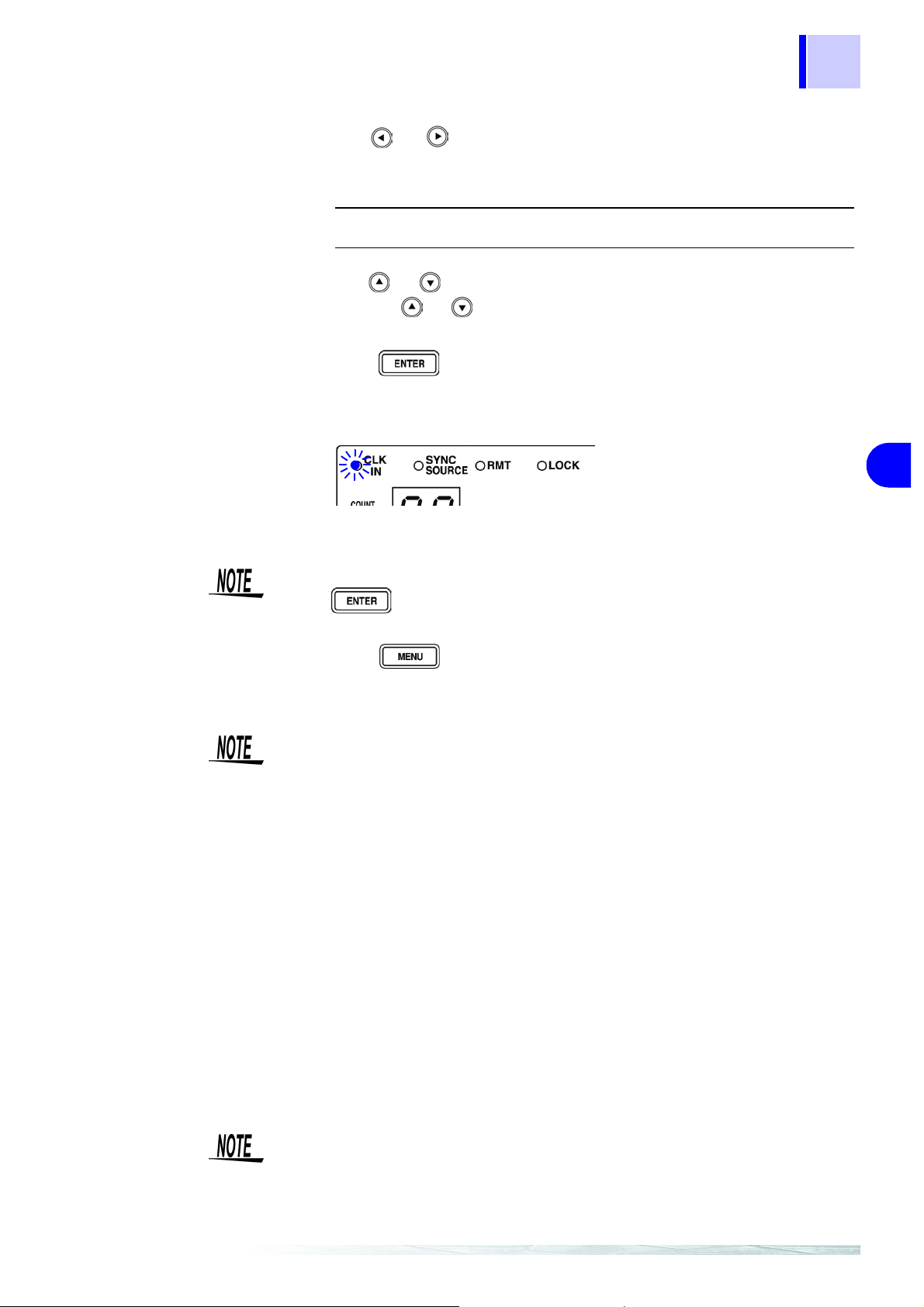
61
4.3 Synchronous Measurement Function (3504 special specification)
2. Use or to select the “CLK” menu item. (Synchronous mea-
surement function setting screen)
The setting ite m s ar e as fol lo w s .
“out”: Master setting (state when using as a standalone unit)
“in”: Slave setting
3. Use or to select a setting item.
Pressing or switches between “out” ÅÆ “in.”
4. Press .
The synchronous measurement function setting is confirmed.
When the slave setting is set, the CLK IN LED lights up.
4
The “SYnC” indication is displayed at the top of the MAIN di sp lay area. (Trigger synchronization output function setting screen)
The synchronous measurement function setting is not confirmed unless
is pressed.
5. Press .
The unit returns to normal measurement mode.
A 3504 unit set t o slave c annot be us ed as a s tandalone unit for measurement.
The measurement value “– – – – – –” is displayed, and the comparator judgment becomes HI and the BIN judgment becomes OUT OF BINS.
Using the Synchronous Measurement Function
1. Set the master and slave.
2. Turn off all the 3504 units.
3. Use a 9679 Connection Cable (option) to connect the SYNC CLK OUT
connector on the rear p anel of a 3504 unit se t to mast er and the SYNC
CLK IN connector on the rear panel of a 3504 unit set to slave.
4. Turn on the 3504 unit set to slave.
5. Turn on the 3504 unit set to master.
• If the 3504 units are tu rned on in the wrong order, the 3504 unit set to
slave will not work properly.
• When changing t he frequency, first cha nge the frequency on the 3504
that was set as the slave unit.
Page 68

62
4.4 Trigger Synchronous Output Function
4.4 Trigger Synchronous Output Function
This function enables the measurement signal to be output after meas urement is triggered and ensures that the signal i s applied to the sample only
during measurement. Thus reducing the generation of heat in the sample and
decreasing electrode wear.
Setting the Trigger Synchronous Output Function
1. In normal measurement mode, press .
The menu items ar e displayed at the top of t he MAIN display area an d the
setting items are displayed at the bottom of the MAIN display area.
• This setting cannot be changed in comparator mode and BIN mode.
• Use and to move through the menu items as follows.
“LoAd_A(C/h)”
ÅÆ “bEEP_K” ÅÆ “CLK” (only for special specifi cations) ÅÆ “SYnC”
ÅÆ “IF.GPib(rS/Prnt)” ÅÆ “LoAd_A(C/h)” ÅÆ …
ÅÆ “SAVE” ÅÆ “Ld_tYP” ÅÆ “JudGE” ÅÆ “b EEP_J”
2. Use or to select the “SYnC” menu item. (Trigger synchronous
output functio n se tt ing screen)
The setting items are as follows.
“on”: Sets the trigger synchronous output function to ON
“oFF”: Sets the trigger synchronous output function to OFF
3. Use or to select a setting item.
Pressing or switches between “on” ÅÆ “oFF.”
4. Press .
The trigger synchronous output function setting is confirmed.
When the trigger synchronous output function is set, the SYNC SOURCE
LED lights up.
After confirmation, “ IF.GPib(rS/Prnt)” is displaye d at the top of the MAIN di splay area. (Interface setting screen)
The trigger synchronous output function setting is not confirmed unless
is pressed.
Page 69

5. Press .
The unit returns to normal measurement mode.
• Only use this func tion withi n the cons tant voltage measu rement rang e. If
it used outside the constant voltage measurement range, accurate values
will not be displayed.
3.3.3 "M easurement Signal Level" (p. 26)
• When the trigger synchronous output function is set to ON, there is a
measurement time delay because the unit enters a wait time which spans
from when the measurement signal is output to when measurement
starts.
• The wait time can be se t from a PC. (At the time of shipment, the wait
time is 2 ms when 1 kHz and 10 ms when 120 Hz.)
Set the optimal wait time for the DUT (device under test).
A wait time that is too short may increase measurement er rors and display differences.
6.1.3 "About Input and Output Signals" (p. 84)
63
4.4 Trigger Synchronous Output Function
4
Page 70

64
4.5 Keylock Function
4.5 Keylock Function
If the keylock function is set, the keys on the front panel are dis abled. This
function enables you to protect your setup.
Setting the Keylock
Press and hold for at least two seconds.
The LOCK LED of the SUB display area lights up.
• All the keys except are locked.
• The following tasks can still be performed when the keylock is set.
In the case of external triggers: Manual triggering is possible.
In the case of inter nal triggers: When t he interface is a printer, the measurement values can be output to the printer.
• The keyl ock can be set in nor mal meas urement mo de, comparato r measurement mode, and BIN measurement mode (only for 3504).
Canceling the Keylock
Press and hold for at least two seconds.
The LOCK LED goes out and the keylock function is canceled.
Turning off the power does not cancel the keylock function.
Page 71

4.6 Panel Save Function
• The current meas ur em ent c onditions can be saved to inte rn al memory. Up
to 99 panels (99 sets) of measurement conditions can be saved.
• When the panel save function is used, the me asurement mode and a ll of
the measurement conditions are saved. The saved values include comparator and BIN (only for 3504) upper limit and lower limit values and the open
circuit, short circuit, and load compensation values.
• Use the panel load function to load saved measurement conditions.
4.7 "Panel Load Function" (p. 66)
Saving Panels
1. Press .
65
4.6 Panel Save Function
The menu items are dis played at the top of the MA IN display area and the
setting items are displayed at the bottom of the MAIN display area.
Use and to move through the menu items as follows.
“LoAd_A(C/h)”
ÅÆ “bEEP_K” ÅÆ “CLK” (only for special specifications) ÅÆ “SYnC”
ÅÆ “IF.GPib(rS/Prnt)” ÅÆ “LoAd_A(C/h)” ÅÆ …
ÅÆ “SAVE” ÅÆ “Ld_tYP” ÅÆ “JudGE” ÅÆ “bEEP_J”
2. Use or to select the “SAVE” menu item. (Panel save function set-
ting screen).
The state becomes as follows.
A panel number that has not been saved lights up at the bottom of the MAIN
display area. (At the time of shipment: “01”)
(If all panels have not been saved, the “01” indication is displayed.)
3. Use the numeri c keypad or and to select the pane l number to
save.
The numbers 01 to 99 can be set.
Panel numbers already in use flash. To overwrite a panel number, select the
panel number to overwrite.
4
4. Press to save the measurement conditions.
The unit returns to the measureme nt mode it was in prior to the menu i tems
being displayed.
• The panel is not saved unless is pressed.
• The lifespan of the backup battery for in ternal memory is appro ximately
six years under normal use.
• Measuremen t conditi ons can no longer be save d after the life of the battery runs out. When this happen s, submit a request for the battery to be
replaced by our repair service personnel. (A fee will be charged.)
Page 72

66
4.7 Panel Load Function
4.7 Panel Load Function
The saved measurement values and compensation values can be loaded
from internal memory.
First, set th e load condition.
There are the following three load conditions.
•All
Loads the measurement conditions (frequency, level, range, upper limit
and lower limit values, etc.) and the open circuit, short circuit, an d load
compensation values.
• Compensation values
Loads the open circuit, short circuit, and load compensation values.
• Measurement conditions
Loads the measurement conditions (frequency, level, range, upper limit
and lower limit values, etc.).
Setting the Load Condition
1. Press .
The menu items ar e displayed at the top of t he MAIN display area an d the
setting items are displayed at the bottom of the MAIN display area.
Use and to move through the menu items as follows.
“LoAd_A(C/h)”
ÅÆ “bEEP_K” ÅÆ “CLK” (only for special specifications) ÅÆ “SYnC”
ÅÆ “IF.GPib(rS/Prnt)” ÅÆ “LoAd_A(C/h)” ÅÆ …
ÅÆ “SAVE” ÅÆ “Ld_tYP” ÅÆ “JudGE” ÅÆ “bEEP_J”
2. Use or to select the “Ld_tYP” menu item. (Load condition setting
screen).
The setting items are as follows.
• “ALL”: Loads the measurement conditions (frequency, level, range,
upper limit and lower limit values, etc.) and the open circuit,
short circuit, and load compensation values.
• “Corr”: Loads the open circuit, short circuit, and load compensation
values.
• “hArd”: Loads the measurement conditions (frequency, level, range,
upper limit and lower limit values, etc.).
3. Use and to select a setting item.
Pressing or switches between “ALL” ÅÆ “Corr” ÅÆ “hArd” ÅÆ
“ALL” …
Page 73

Loading Panels
67
4.7 Panel Load Function
4. Press .
The load condition sett ing is confirmed. The “J udGE” indication is displayed
in the MAIN display area. (Judgment mode selection screen)
The load conditio n setting is not confirmed unless is pressed.
5. Press .
The unit returns to the measureme nt mode it was in prior to the menu i tems
being displayed.
4
1. Press .
The menu items are dis played at the top of the MA IN display area and the
setting items are displayed at the bottom of the MAIN display area.
Use and to move through the menu items as follows.
“LoAd_A(C/h)”
ÅÆ “bEEP_K” ÅÆ “CLK” (only for special specifications) ÅÆ “SYnC”
ÅÆ “IF.GPib(rS/Prnt)” ÅÆ “LoAd_A(C/h)” ÅÆ …
ÅÆ “SAVE” ÅÆ “Ld_tYP” ÅÆ “JudGE” ÅÆ “bEEP_J”
2. Use or to select the “LoAd_A(C/h)” menu item. (Panel load
screen)
There are three types of panel load screens.
• “LoAd_A” Loads the measurement conditions and the open circuit,
short circuit, and load compensation values.
• “LoAd_ C” Loads th e open ci rcuit, s hort ci rcuit, and load c ompen satio n
values.
• “LoAd_h” Loads the measurement conditions.
The panel load screen that is displayed differs depending on the load condition set in 4.6 "Panel Save Function" (p. 65). (Refer to the following table.)
For details on changing the load condition setting, refer to "Setting the Load Con-
dition" (page 66).
Load Condition Setting Panel Screen Displayed
ALL
Corr
hArd
"LoAd_A”
“LoAd_C”
“LoAd_h”
Page 74
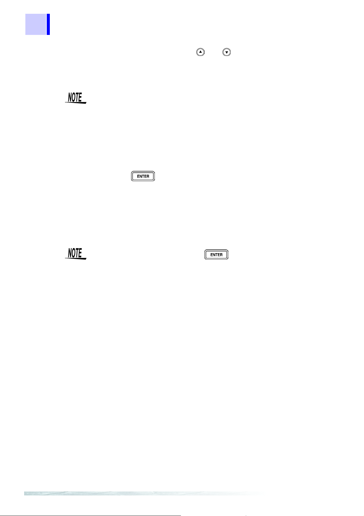
68
4.7 Panel Load Function
3. Use the numeric keypad or and to select the panel number to
load.
The number is entered at the bottom of the MAIN display area.
• Only saved number s can be s et. If a numbe r that was not save d with the
numeric keypad is set, the set number fl ashes and then changes to the
nearest saved number after one second elapses.
• At the time of s hipment, when the unit has been reset, or at any other
time when there are no measurement conditions saved, “– –” is displayed
at the bottom of the MAIN display area.
• Each time a panel number is changed, the LED (in the operation area) for
the measurement conditions of that panel number flashes.
4. Press to load the measurement conditions.
When the load condition is set to ALL (measurement conditions and compensation values) or hArd (measurement conditions), the unit switches to the
saved measurement mode.
When the load condition is set to Corr (compensation values), the unit returns
to the measurement mode it was in prior to the menu items being displayed.
• The panel is not loaded unless is pressed.
• When loa din g a panel from EXT I/O, the wait time (the time f ro m t he trigger being input to the start of measurement) varies depending on the load
condition.
•ALL: Approximately 300 ms
•Compensation values: Approximately 0.5 ms
•Measurement conditions: Approximately 300 ms
Page 75
4.8 Printing Function
4.8 Printing Function
The optional 9442 Printer and 9444 Connection Cable can be used to print
measurement values.
To avoid electric shock, turn off the power to all devices before plugging or unplugging any cables or peripherals.
4.8.1 Preparation Prior to Connecting the Printer
Things to Prepare • 9442 Printer (DPU-414 Seiko Instruments Inc.)
• 9443-01 AC Adapter (for Japan) (PW-4007-J1-E or PW-4007-JU1-E
(power cord CB-JP01-18B-E), Seiko Instruments Inc.)
• 9443-02 AC Adapter (for EU) (PW-4007-E1-E, Seiko Instruments Inc.)
• 9443-03 AC Adapter (for USA) (PW-4007-U1-E, Seiko Instruments Inc.)
• 1196 Recording Paper
• 9444 Connection Cable
(for connecting this unit and the pr inter)
69
4
9442 Printer Setup
Procedure
1. Turn off power of the 9442 Printer.
2. Turn the power back on while holding down the ON LINE switch, and
The settings of the software D IP SW need to be changed to use the 9442
Printer with this unit.
• At the time of shipment, the 9442 Pri nter is configured to be connected
and used with the Hioki 3166 Clamp On Power HiTester. Be sure to
change the settings of the software DIP SW.
• For details on handl ing the pri nter, be sure to careful read the ins tructi on
manual supplied with the printer.
• Use 1196 Recording Paper (therma l paper ; 10 roll s per set ) or the equi valent as the printer paper.
then let go of the switch when printing starts.
The current settings are printed.
The following is printed at the end of the printout.
Continue? :Push 'On-line SW'
Write? :Push 'Paper feed SW'
Page 76

70
4.8 Printing Function
3. Press the ON LINE switch to change the settings.
“Dip SW-1” is printed and the printer enters the configurati on state for the
software DIP SW1.
4. Set the switches numbered 1 to 8 of DIP SW1 to either ON or OFF in
accordance with the table below.
Press the ON LINE switch once to set a switch to ON and the FEED
switch once to set a switch to OFF.
You can confirm the input result that is printed each time a switch is
pressed. If a setting is configured incorrectly, repeat the procedure from
Step
Software DIP SW1 Settings
1. (page 69).
is the setting to use with thi s unit.
Switch
No.
1 Input method setting Parallel Serial
2 Print speed
3 Auto loading
4 CR function Carriage return
5 Setting command
6
Print density (set to
7
100%)
8
After you finish co nfiguring the switch numbered 8, the following is printed
again.
Function
Fast Slow
Enable Disable
Enable Disable
ON
ON
ON
(Press ON LINE)
OFF
(Press FEED)
Return
OFF
Continue? :Push 'On-line SW'
Write? :Push 'Paper feed SW'
5. Press the ON LINE switch again so that the printer enters the configu-
ration state and configure each of the settings for DIP SW2 and DIP
SW3 as shown in the table below.
Software DIP SW2 Settings
Switch
No.
1Print mode
2
3 Character type
4 Zero font
5
6
7
8 ON
Function
User-defined
character backup
International characters
Normal print
(40 digits)
Enable Disable
Normal characters Special characters
0Ø
ON
ON
ON
ON
(Press ON LINE)
OFF
(Press FEED)
Reduced print
(80 digits)
Page 77
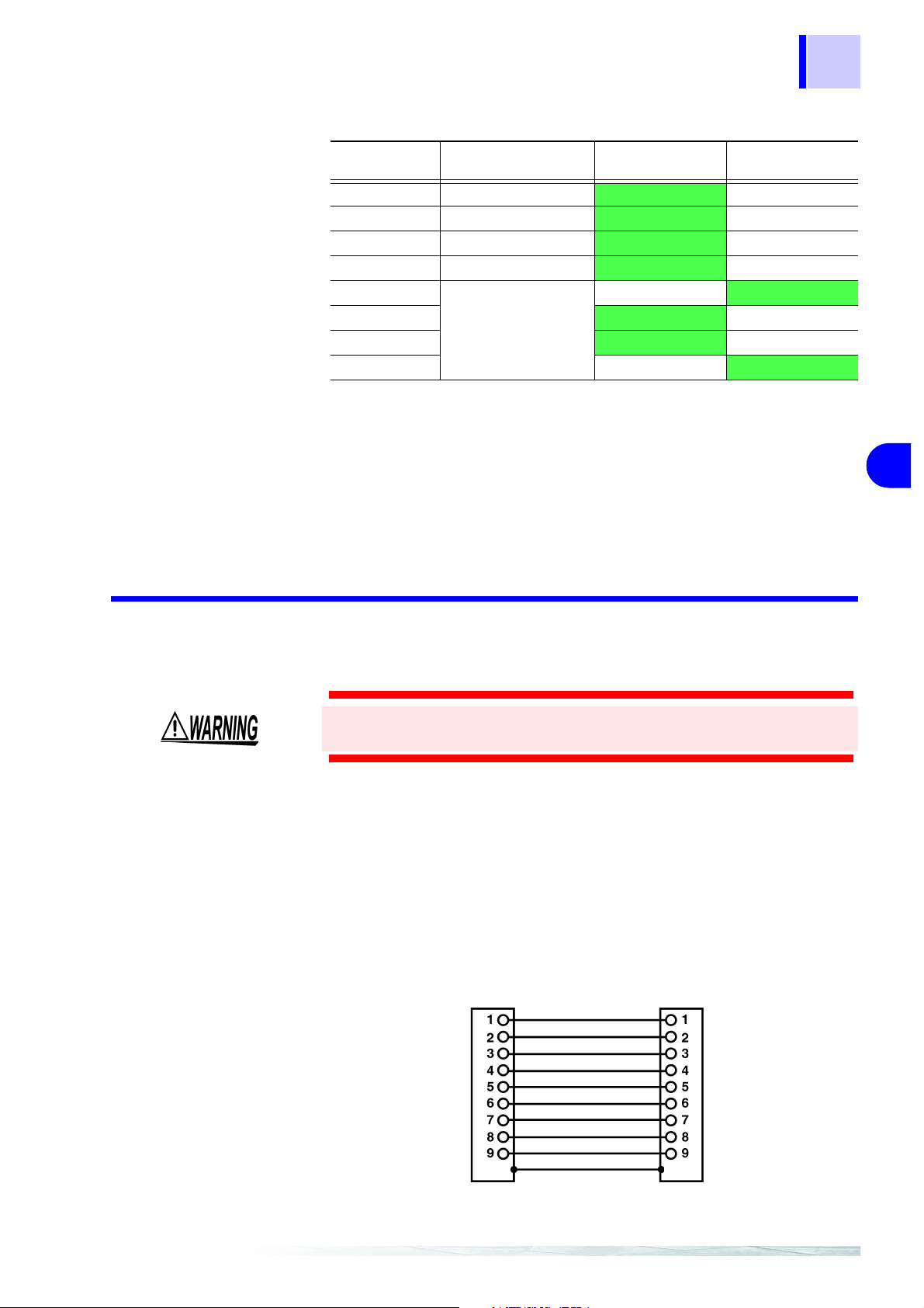
Software DIP SW3 Settings
C
71
4.8 Printing Function
Switch No. Function
1 Data bit length 8 bits 7 bits
2 Use parity
3 Parity setting
4 Control flow
5
6 ON
7
8
Baud rate
(Set to 19200 bps)
No Yes
Odd Even
H/W BUSY XON/XOFF
ON
ON
(Press ON LINE)
OFF
OFF
OFF
(Press FEED)
6. After you finish configuring the switch numbered 8 of DIP SW3, press
either the ON LINE switch or the FEED switch to complete the setup.
The following is printed.
Dip SW setting complete!!
4
4.8.2 Connection Procedure
To avoid electric shock, be sure to turn off the power of the printer and
unit before you connect or disconnect a cable.
Connect the 9442 Printer to the RS-232C connector of the unit.
Configure the printer and unit beforehand.
7.3.2 "Setting the Interface Communication Conditions" (p. 96)
Procedure
1. Turn off the power of the 3504 (3504-10) unit and the 9442 Printer.
2. Connect the 9444 Connection Cable to the unit and the printer.
onnection
BB(RxD)
BA(TxD)
CD(DTR)
AB(GND)
CA(RTS)
CB(CTS)
3504(3504-10)
9442 Printer
BA(TxD)
BB(RxD)
AB(GND)
CA(RTS)
Frame
Frame
Page 78
72
4.8 Printing Function
3. Turn on the power of the 3504 (3504-10) unit.
4. Turn on the power of the 9442 Printer.
4.8.3 Printing
Turn on the power of the 3504 (3504-10) unit before you turn on the
power of the
3504 (3504-10) unit, undefined values may be sent from the 3504 (35 04-
10)
unit because of BA(TxD) being unstable.
If is pressed when an ex terna l t rigge r is set , the m easur ement values are output to the printer after measurement finishes.
If is pressed when a n internal trigger is set, the meas urement values up until the time when the key is pressed are output to the printer.
9442 Printer. If the 944 2 Print er is on when you turn on the
1. Example when performing normal measurement
CP 100.034n F |D 0.00041
CP 100.029n F |D 0.00038
2. Example when performing comparator measurement
CP 100.052n F HI|D 0.00050 HI
CP 100.047n F IN|D 0.00045 IN
3. Example when performing BIN measurement (only for 3504)
CP 100.016n F |D 0.00042 BIN1
CP 100.023n F |D 0.00036 OUTB
Connecting a PC instead of the 9442 Printer enables you to receive the measurement values on the PC.
Set the RS-232C communication conditions on the PC as shown below.
• Bits per second: 19200
• Data bits: 8
• Parity: None
• Stop bits: 1
Flow control is automatically set to Hardware (RTS/CTS control) if the
interface used with the
3504 (3504-10) unit is a printer .
Page 79
5.1 Setting Beep Tones
Other Settings Chapter 5
5.1 Setting Beep Tones
Setting the Beep Tone for Judgment Results of Comparator and BIN (only for 3504)
Any of following three settings is possible for the beep tone.
• A beep tone is not played.
• A beep tone plays when th ere is an IN judgment (AND) fo r both C and D
during comparator measur ement and a judgment cor responding to a BIN
number during BIN measurement.
• A beep tone plays whe n there is a HI or LO judgment during comparator
measurement and an OUT OF BINS or D-NG judg ment during BIN m easurement.
73
Setting the Beep Tone for Key Operations
5.1.1 Setting the Beep Tone for Judgment Results of Comparator and BIN
1. In normal measurement mode, press .
The menu items are dis played at the top of the MA IN display area and the
setting items are displayed at the bottom of the MAIN display area.
• This setting cannot be changed in comparator mode and BIN mode.
• Use and to move through the menu items as follows.
“LoAd_A(C/h)”
“bEEP_K” ↔ ”CLK” (only for special specifications) ↔ ”SYnC” ↔
”IF.GPib(rS/Prnt)” ↔ “LoAd_A(C/h)” ↔ ...
↔ ”SAVE” ↔ ”Ld_tYP” ↔ ”JudGE” ↔ “bEEP_J” ↔
5
2. Use or to select the "bEEP_J" menu item. (Beep tone setting
screen for judgment results)
The setting items are as follows.
"oFF" : A beep tone is not played regardless of the judgment results.
"in" : A beep tone plays when there is an IN judgment (AND) for both C
and D during comparator measurement and a judgment
corresponding to a BIN number during BIN measurement.
"nG" : A beep tone plays when there is a HI or LO judgment during
comparator measurement and an OUT OF BINS or D-NG
judgment during BIN measu re men t.
Page 80

74
5.1 Setting Beep Tones
3. Use or to select a setting item.
Pressing or switches between “oFF”↔“in”↔“nG”↔“oFF”...
4. Press .
The beep tone set ting for judgment results is confir med. The " bEEP_K" indication is display ed in the MAIN display area. (Beep tone setting screen for
key operations)
The beep tone setting for judgment results is not confirmed unless
is pressed.
5. Press .
The unit returns to normal measurement mode.
5.1.2 Setting the Beep Tone for Key Operations
1. Press .
The menu items ar e displayed at the top of t he MAIN display area an d the
setting items are displayed at the bottom of the MAIN display area.
Use and to move through the menu items as follows.
“LoAd_A(C/h)”
“bEEP_K” ↔ ”CLK” (only for special specifications) ↔ ”SYnC” ↔
”IF.GPib(rS/Prnt)” ↔ “LoAd_A(C/h)” ↔ ...
↔ ”SAVE” ↔ ”Ld_tYP” ↔ ”JudGE” ↔ “bEEP_J” ↔
2. Use or to select the "bEEP_K" menu item. (Beep tone setting
screen for judgment results)
The setting items are as follows.
“on” : A beep tone plays when a key operation is performed.
“oFF” : A beep tone is not played when a key operation is performed
3. Use or to select a setting item.
Pressing or switches between “on”↔“oFF”.
4. Press .
The beep tone setting for key operations is confirmed.
Page 81

After confirmation, "CL K" is displayed at the top of th e MAIN display area if
there is a sync hron o us me as urem e nt f unc ti on an d "SY nC " (tri gge r sy nc hr on ization output func tion setting screen) i s displayed if there is no s ynchronous
measurement function.
The beep tone setting for key operations is not confirmed unless is
pressed.
5. Press .
The unit returns to the measureme nt mode it was in prior to the menu i tems
being displayed.
75
5.1 Setting Beep Tones
5
Page 82

76
g
5.2 Performing a System Reset
5.2 Performing a System Reset
Performing a system reset returns all the measurement conditions to their initial states at the time of shipment. These measurement conditions also
include measurement conditions saved for panels.
Reset Procedure
1. Turn the power of the unit off.
2. Turn the power back on while holding down , and then let go
of when the version information is displayed.
The version infor mation is displayed for approx imately 15 seconds after all
LEDs light up. Then, the system reset setting is displayed.
System reset settin
item
3. Use to set system reset while the indication is displayed.
A system reset is not performed.
A system reset is performed.
4. Press to confirm the setting.
If a system reset is perfo rmed, all the measur ement conditions are r eturned
to their initi al states at the time of shipme nt and the unit returns t o normal
measurement mode.
Page 83

The initial settings at the time of shipment are as follows.
Measurement Mode Normal Measurement Mode
Measurement Frequency 1 kHz
Measurement Signal Level 1 V
Measurement Speed NORMAL
Equivalent Circuit Mode AUTO
Measurement Range AUTO
Open Circuit Compensation OFF
77
5.2 Performing a System Reset
Open Circuit Compensation Value
Output Parameter
Short Circuit Compensation OFF
Short Circuit Compensation Value
Output Parameter
Load Compensation OFF
Load Compensation Value Output
Format
Trigger Mode INT (Internal Trigger)
Header ON
Trigger Synchronous Output Func-
tion
Lock Function OFF
Beep Tone Setting The key operation beep tone is ON and the comparator and BIN judg-
Panel Save All conditions are cleared
Comparator (1st/2nd Parameter)
ZPH
ZPH
Reference Values (C,D)=(100000, 0)
COEFficient
OFF
ment results beep tone is OFF.
Count Setting Value The upper limit and lower limit values are OFF.
Deviation Percent Sett ing V alue
C reference value: 1000 00
D reference value: 0
The upper limit and lower limit values are OFF.
5
BIN (only for 3504) (1st/2nd Parameter)
Count Setting Value The upper limit and lower limit values are OFF.
Deviation Percent Sett ing V alue
C reference value: 1000 00
D reference value: 0
The upper limit and lower limit values are OFF.
Interface Setting 3504 Interface :GP-IB
Address :1
Terminator :LF with EOI
3504-10 Interface :RS-232C
Baud Rate :9600 bps
Terminator :CR+LF
Reset EXT I/O Judgment Results ON
The settings of the RS-232C interface in the 3504 unit are initialized to 9600
bps for the baud rate and CR+LF for the terminator.
Page 84

78
5.3 Countermeasures Against Incorporation of External Noise
5.3 Countermeasures Against Incorporation of External Noise
The unit is designed not to malfunction as a result of noise incorporat ed from
the probes, fixture , and power li ne. However, extremely large l evels of no ise
may still cause measurement errors and malfunctions.
Refer to the followi ng examples of c ountermeasures against noise wh en the
unit malfu nctions, etc
5.3.1 Countermeasures Against Incorporation of Noise from the Power Line
You can use the following countermeasures to reduce the effect of noise
being incorporated from the power line.
Grounding Using a Protective Ground Wire
The unit is structured so that the ground wire of the power cable can be used
as protective gr ounding for t he unit. Pr otective g rounding pl ays an importa nt
role in not only the prevention of el ectrical accidents but also the use of an
internal filter to eliminate the incorporation of noise from the power line.
Use the supplied power cord.
Attaching a Noise Filter to the Power Line
Connect a commercial plug-in noise filter to the power outlet and then connect the unit to the output of the noise filter in order to supp ress the i ncorporation of noise from the power line.
Plug-in nois e fil ter s ar e comme rci all y av aila ble fr om v ario us specia li st manufacturers.
Page 85

5.3 Countermeasures Against Incorporation of External Noise
Attaching an EMI Suppression Ferrite Core to the Power Cord
Pass the power cord th rough a commer cially avail able EMI suppres sion ferrite core and secure the core as close as possible to the AC power inlet of the
unit in order to suppress the incorporation of noise from the power line.
Suppression is even more effective if you also attach an EMI suppression ferrite core close to the power plug of the power source.
If a toroidal ferr ite core or split ferrite c or e wi th a large enough internal di ameter is used, t he amount of noise suppress ion can be inc reased by passing
the power cord through the core several times.
EMI ferrite core s and ferrite beads are com mercially available from va rious
specialist manufacturers.
79
5.3.2 Countermeasures Against Incorporation of Noise from the Input Line (Types of Probe)
You can use the following countermeasures to reduce the effect of noise
being incorporated from, for example, a probe or fixture.
Attaching an EMI Suppression Ferrite Core to Commercial Cables
Noise from things like probes can be suppressed if y ou pass them through
commercially available EMI suppression ferrite cores and secure the cores as
close as possible to the measurement terminals. Furthermore, if large
enough ferrite cores are used, the amount of noise suppression can be
increased by passi ng things like probes through th e cores several times in
the same manner as with the power cord.
5
EMI Suppression Ferrite Core
Page 86

80
5.3 Countermeasures Against Incorporation of External Noise
Page 87

6.1 Measurement Using EXT I/O
79
Application
Measurement Chapter 6
6.1 Measurement Using EXT I/O
6.1.1 About the EXT I/O Connector
The EXT I/O connector includes the following functions.
• Output signal for comparator result
• Output signal for BIN result (only for 3504)
• Output end of measurement signal (/EOM)
• Output analog end of measurement signal (/INDEX)
• Input external trigger signal
• Select the panel number to load
81
Connector Used DDK 57RE-40500-730B (D29)
Applicable Connector DDK 57-30500
EXT I/O Connector Terminal
PIN No. I/O
1 IN /TRIG 26 IN /LD0
2 IN /LD1 27 IN /LD2
3IN /LD3 28IN /LD4
4 IN /LD5 29 IN /LD6
5 IN /LD-VALID 30 OUT /BIN1, /C-HI
6 OUT /BIN2, /C-IN 31 OUT /BIN3, /C-LO
7 OUT /BIN4, /D-HI 32 OUT /BIN5, /D-IN
8 OUT /BIN6, /D-LO 33 OUT /BIN7, /AND
9 OUT /BIN8 34 OUT /BIN9
10 OUT /BIN10 35 OUT /BIN11
11 OUT /BIN12 36 OUT /BIN13
12 OUT /BIN14 37 OUT /OUT OF BINS
13 OUT /INDEX 38 OUT /EOM
14 OUT /CV-ERR 39 OUT /D-NG
15 - Unused 40 - Unused
16 to 20 IN EXT DCV 41 to 45 OUT INT DCV
21 to 25 IN EXT COM 46 to 50 OUT INT COM
25 1
50 26
Signal Line
Name
*The output of BIN results is only for 3504.
PIN No. I/O
6
Signal Line
Name
Page 88

82
6.1 Measurement Using EXT I/O
EXT I/O Connector Signal Lines
All input and output signals other than the power signal are negative logic.
TRIG If a negative logic signal is inpu t in external trigge r mode, a single measu re-
ment begins at the corresponding LOW level (100
This is not valid during analog measurement (during output of INDEX
signal), even if a TRIG signal is input.
LD0Å`LD6 Selects the number of the panel to load.
If a trigger signal is input in external trigger mode, the selected panel is
loaded and used for measurement.
μs or more).
Panel
Number
Panel 1 0000001
Panel 2 0 0 0 0 0 1 0
Panel 4 0000100
Panel 8 0 0 0 1 0 0 0
Panel 160010000
Panel 32 0 1 0 0 0 0 0
Panel 641000000
Panel 99 1 1 0 0 0 1 1
LD-VA LID Inputs a negative logic signal from an external device so that the selected
panel number is recognized as valid.
C-HI, C-IN, C-LO Outputs the comparator judgment result for the measurement value of the
first parameter (MAIN PARAMETER).
D-HI, D-IN, D-LO Outputs the comparator judgment result for the measurement value of the
second parameter (SUB P A RAMETER).
AND Outputs a result if the judgment result AND is obtained for the measurement
value of the first parameter and the measurement value of the second parameter.
Outputs a result if both judgments re sults are IN or if one of eit her the firs t or
second parameters was not judged but the judgment result of the judged
parameter is IN.
/LD6 /LD5 /LD4 /LD3 /LD2 /LD1 /LD0
BIN1 to BIN14
OUT OF BINS
D-NG
/INDEX This is the analog end of me asu remen t signa l. Af ter t hi s sign al is set to ON (from
/EOM This is the end of measurement signal.
EXT DCV, EXT COM This terminal supplies power from an external devi ce. It enables an isolat ed
INT DCV, INT COM Outputs internal +5 V DC and internal COM of the unit.
CV-ERR This outputs a signal when the voltages of both ends of th e sample fall out-
Outputs judgment results for BIN measurement (only for 3504).
the trailing edge), the samp le can be changed.
connection to be estab lished between the unit and an ext ernal device. The
range of power voltages that can be connected is 5 to 24 V DC.
side the ±10% range of the set voltage.
Page 89

83
6.1 Measurement Using EXT I/O
6.1.2 Circuit Configuration and Connections of the EXT I/O Connector
• The range of power voltages that can be connected to the external DC
power supply EXT DCV and EXT COM termin als is 5 to 24 V DC. Do not
apply a voltage that exceeds +24 V DC. Doing so may damage the device.
Connect a device with an output capacitance o f a t l eas t 200 mA in order to
drive the circuit.
• Signal lines a re insulated to st op interferen ce between signal s. Be sure to
use protective grounding for the connected device. Otherwise the insulation
may be damaged.
• +5 V DC is output between the internal DC powe r supply INT DV C and
INT COM. The maxi mum current c apacity is 100 mA. Do not conn ect a
circuit that consumes 100 mA or more to an external device.
• INT COM is connected to the case.
• The maximum low level output current of the output signal is 30 mA.
When a current of mo re than 3 0 mA i s requi red, con nect, for example , a
transistor circuit, which is capable of current am plification and run on an
external power source, to the external device.
Circuit Configuration All input and ou tput sign al lines oth er than the po wer signal li ne are iso lated
by a photocoupler.
Internal DC power supply (5 V)*
INT DCV
Pull-up resistor
Ω (1/4 W)
3.3 k
The ground is connected to the
case
* A connection is possible when using an internal DC power supply voltage
of 5 V.
External DC power supply (5 to 24 V)*
EXT DCV
, C-HI
BIN1
BIN2, C-IN
EOM
TRIG
LD0 to LD6
External DC power supply (COM)*
EXT COM
Internal DC power sup ply (COM)*
INT COM
6
Page 90

84
6.1 Measurement Using EXT I/O
6.1.3 About Input and Output Signals
Electrical Characteristics of Output Signals
The output signals are photocoupler ope n collector output . Inside the unit, a
3.3 k
Ω pull-up resistor is used to connect to the exter nal DC power source
(EXT DCV).
Relation Between
External DC Po wer
Source Voltage
and Output Signal
Voltage/Current
External DC
Power
Source
55
24 24
It is not possible to dir ectly connect a cir cuit that has a maximum inp ut voltage V
so that the V
of 0.8 V or more. Add a transistor and buffer circuit capable of driving
IL
Output Signal (Internal Pull-up Resistor of 3.3 kΩ)
Low Level (Output Current)
High Level
(10 mA) (30 mA)
0.9 V12 12 1.1 V
becomes less than 0.8 V.
IL
Timing of Input Signals
Set the judgment condit ions with the comparator and input a trigger signa l
from EXT I/O in that state. (The trigger setting is set to external trigger.)
If you press , the judgment result is output from the EX T I/O comparator result output signal line.
Measurement Timing
Example
(Start-of-measurement signal)
(Analog end of measurement signal)
(End of measurement sign al)
, IN, LO, CV-ERR
HI
(Comparator result o utp ut)
TRIG
INDEX
EOM
T1
T2
Last judgment
result
Reset at the same time as TRIG: HIGH
Not reset at the same time as TRIG
T5
T3
T4
Judgment
result
: LOW
You can use a communication command to select whether the judgment
results for comparator measurement and BIN measur ement ar e reset when
the start-of-measurement signal is input or updated when measurement
ends.
Page 91

6.1 Measurement Using EXT I/O
85
Symbol Description
T1 TRIG width (LOW) : Trigger signal minimum time 100 μs
T2 From TRIG (LOW) to /INDEX (HIGH) : Time from trigger to circuit response 200 μs *1
T3 /INDEX width (HIGH) : Minimum chuck time, switching chuck
with /INDEX (LOW) is possible
T4 /EOM width (HIGH) : Measurement time 2.0 ms *2
T5 From /EOM width (LOW) to TRIG (LOW): Minimum time from end of measurement
to next trigger
*1: When the range is 8 and there is no trigger input for at least 10 minutes at the
external trigger, the response times may become 2 ms (1 k Hz) and 8 m s (120 Hz ).
When the panel number is being loaded by the panel load function, the response
times become approximately 0.5 ms (loading compensation values) and approximately 300 ms (ALL, loading measurement conditions).
When the trigger synchronous output function is enabled, wait times are included.
(The wait times at the time of shipment are approximately 2 ms [1 kHz] and 10 ms
[120 Hz] and can be changed from a PC.)
*2: These reference values are when the measurement frequency is 1 kHz, the mea-
surement speed is FAST, and the range is HOLD.
Approximate
1 ms *2
Time
0 s
6
Page 92

86
6.1 Measurement Using EXT I/O
6.1.4 About Measurement Times
Measurement times di ffer depending on the m easurement conditi ons. Refer
to the following values.
• All o f the va lues are r eferenc e values . Note that t hey ma y differ d epending on the conditions of use.
• A wait of 300 ms is included when the frequency, level, and range
change.
Analog M e as urement Signal
INDEX
End of Measurement Signal
EOM
The output time (T3) for an analog measurement signal (INDEX) depends on
the measurement frequency and measurement speed as shown below.
(When the range is HOLD.)
Measurement Speed
Measurement Frequency
120 Hz 8.3 33.3 133.3
1 kHz 1 4 24
(Allowable tolerance:
The output time (T4) for an end of measurement signal (EOM) can be
obtained by the following equation.
T4 = A + B + C + D
±5%±0.3 ms)
FAST NORM SLOW
T3 (ms) T3 (ms) T3 (ms)
A These measurement times are for when the unit is in normal measurement
mode and not performing open circuit and short circ uit compensation, and
when the range is HOLD.
Measurement
Frequency
120 Hz 10.0 37.5 146.0
1 kHz 2.0 5.5 29.5
(Allowable tolerance:
FAST (ms) NORM (ms) SLOW (ms)
±5%±0.5 ms)
Measurement Speed
B The calculation time differs depending on whether or not there is open circuit,
short circuit, or load compensation
Open Circuit and Short Circuit Compensat ion (ms)
No 0.0
Yes Max. 0.4 Each
C The calculation time differs if comparator is executed.
Measurement Mode (ms)
Normal Measurement Mode 0.0
Comparator Measurement Mode MAX 0.4
D The calculation time differs if BIN is executed. (Only for 3504.)
Measurement Mode (ms)
Normal Measurement Mode 0.0
BIN Measurement Mode MAX 0.4
Page 93

6.2 Measurement of High Impedance Components
6.2 Measurement of High Impedance Components
Since high i mpedance c omponents (f or example , capacitor s of 1 μF or less)
are susceptible to things like external ind uction noise, measurement values
may become unstable. When th is hap pen s, stable m easur ement can be pe rformed by measuring components on a metal plate connected to the GUARD
terminal (shielding process).
87
Resin Film
Metal Plate
When measuring compon ents on a metal plate, use, for examp le, resin film
as insulation to ensure terminals and the like are not short-circuited.
Open circuit compens ation is high impedance measurement, so be sure to
use the shielding process. If it is not used, the compensation values may
become unstable and affect the measurement values.
6
Page 94

88
6.3 Measurement of In-circuit Components
6.3 Measurement of In-circuit Components
6.3.1 Measurement Using Guardin g Technique
Measure an in-circuit component after providing guarding.
CC2
C3 C4×
-------------------+=
C3 C4+
HL
C
1
C
2
C
3
C
HL
C
1
C
2
C
3
C
When measuring the capacitance of
capacitor C
as shown in the diagram,
2
measure th e p arall el cap a cita nce by ad ding up the value of the curren t that flows
through capacitor C
and the values of
2
the current that flow s through capacitors
and C4, after the probes are con-
C
3
nected to both sides of capacitor C2.
4
If you use a guard terminal as shown in
the diagram, however, the current does
not flow through capacitor C
current that flows thr ough capacitor C
and the
4
is
3
absorbed by the guard terminal so that
you can measure the capacitance of
4
capacitor C
.
2
To guard terminal
• However, if, for example, the capacitance of C2 is less than that of C
(C2<< C3), this technique does not improve measurement precision.
• When two capaci tors or a capacitor and a coil are connected in paralle l
as shown in the diagram, you cannot measure each component separately.
Two capacitors connected
in parallel
A coil and a capacitor con-
nected in parallel
3
Page 95
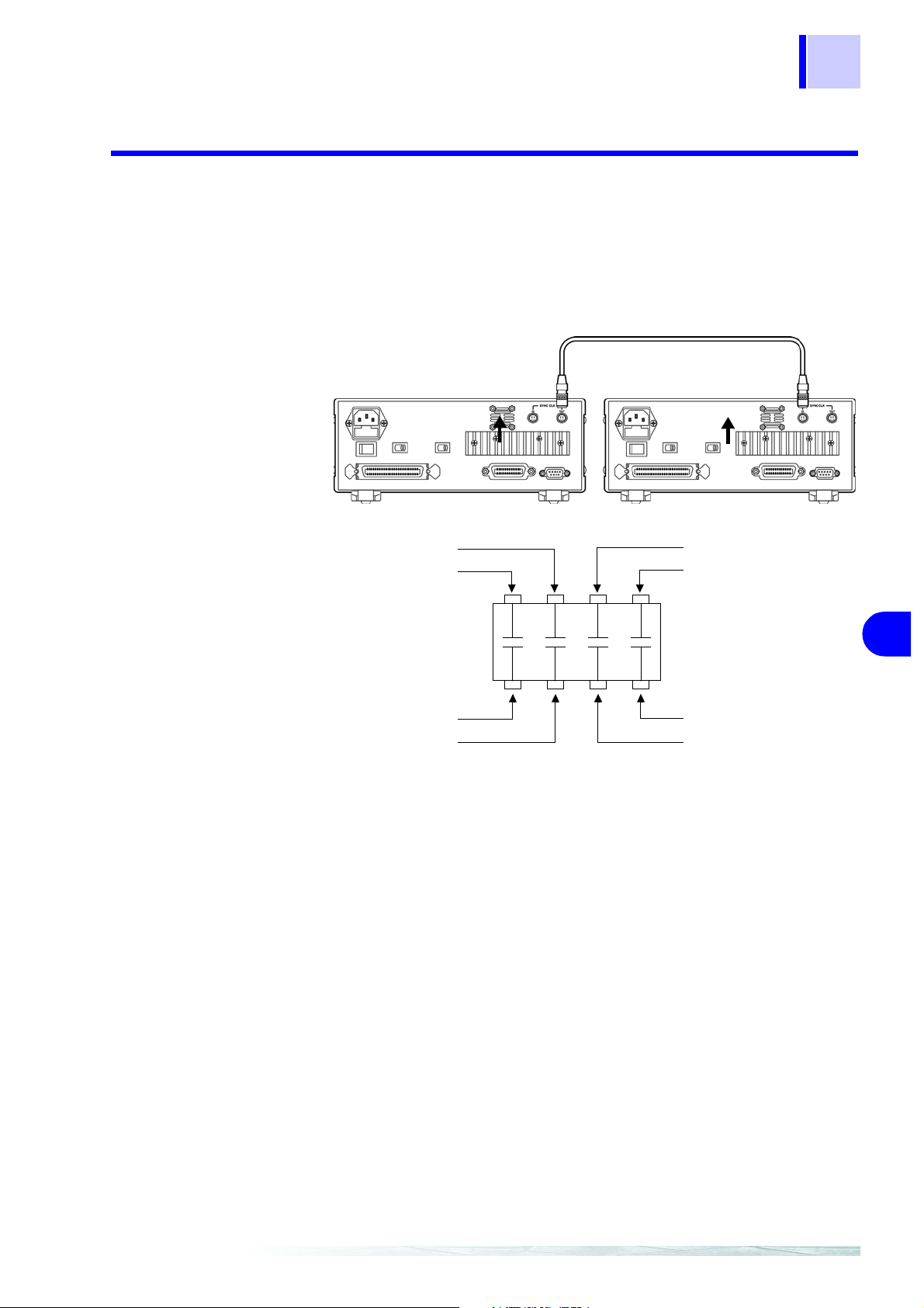
6.3 Measurement of In-circuit Components
6.3.2 Synchronous Measurement
You can measure an in-circuit component using multiple 3504 (3504-10)
units.
Configure the units for th e state of synchronous measurement and set the
measurement signal and frequency for each unit to the same conditions.
Setting Procedure : 4.3 "Synchronous Measurement Function (3504 special speci-
fication)" (p. 60)
89
OUT
H
4
L
4
IN
H
3
H
2
H
1
6
L
1
L
3
L
2
Page 96

90
6.3 Measurement of In-circuit Components
Page 97

7.1 Outline and Features
117
Controlling the Unit
from a PC Chapter 7
About Marks
The following marks are used in this section to indicate whether a description
applies to each of GP-IB and RS-232C. If no specific mark is shown, the
description applies to both.
Only for GP-IB (only for 3504)
:
Only for RS-232C
:
91
7.1 Outline and Features
You can connect a PC to the unit via the GP-IB interface or RS-232C interface and control the unit from the PC.
• All functions other than the power switch can be controlled.
• The buzzer tone can be switched on and off.
• The system ca n be rese t.
Measurement resul ts can be printed if you con nect an optional 9442 Pri nter
to the unit.
4.8 "Printing Function" (p. 69)
7
3504, 3504-10
RS-232C cable or GP-IB cable
• Use of the common commands of IEEE-488-2 1987 (required) is possible.
• This function is compliant with the following standard. : IEEE-488.1 1987
• This functi on was designed in reference to the foll owing standard: IEEE-
488.2 1987
Page 98

92
7.2 Specifications
7.2 Specifications
7.2.1 RS-232C Specifications
Transmission Method Communication method: Full duplex
Synchronous method: Start-stop synchronization
Transmission Speed 9600 bps, 19200 bps
Data Bits 8 bits
Parity None
Stop Bits 1 bit
Message Terminator (Delim-
iter)
Flow Control Hardware (RTS/CTS control), software (XON/XOFF control)
Electrical Specifications Input voltage level
CR+LF, CR
"Handshake (About Buffer Flow Control)" (p. 92)
5 to 15 V ON
-15 to -5 V OFF
Output voltage level
5 to 9 V ON
-9 to -5 V OFF
If a PC is used to read data from th e 3504 (350 4-10) un it immediatel y after
the power of the 3504 (3504-10) unit is turned on, undefined values may be
read because of BA(TxD) being unstable. After turning the power on, wait at
least six seconds before starting to read data.
Handshake (About Buffer Flow Control)
Control during
Receiving
When using hardware (RTS/CTS control):
When the data in the rece ive buffer exceeds 85% of t he buffer, CA(RTS) is
set to OFF and the controller is not ifi ed that th ere i s not mu ch space re maining in the buffer.
Processing of the data in the buffer continues, and then CA(RTS) is set to ON
and the controller is notified that there is sufficient remaining space in the
buffer when the amount of data becomes less than 25%
When using software (XON/XOFF control):
When the data in the receive buffer exceeds 75% of the buffer, XOFF(13H) is
sent and the controller is notif ied that there is not muc h space remaining in
the buffer.
Processing of the data in the buffe r continues, and then XON(11H) is sent
and the controller is notified that there is sufficient remaining space in the
buffer when the amount of data becomes less than 25%
.
.
Page 99

Input Buffer
Usage Amount
Buffer Space
85%
75%
25%
CA(RTS)
Send XOFF
93
7.2 Specifications
ON
OFF
Send XON
Control during
Sending
When using hardware (RTS/CTS control):
When CB(CTS) is confirmed to be OFF, the sending of data is halted. When it
is confirmed to be ON, the sending of data is resumed.
When using software (XON/XOFF control):
When XOFF is received, the sending of data is halted. When XON is
received, the sending of data is resumed.
7.2.2 GP-IB Specifications (Only for 3504)
Interface Functions
SH1 Supports all source handshake functions.
AH1 Supports all acceptor handshake functions.
T6 Supports standard talker functions.
Supports serial poll functions.
Talk only mode is not supported.
Supports the talker cancel function by MLA (My Listen Address).
L4 Supports standard listener functions.
Listener only mode is not supported.
Supports the listener cancel function by MT A (My Talk Address).
SR1 Supports all service request functions.
RL1 Supports all remote/local functions
PP0 Parallel poll functions are not supported.
DC1 Supports all device clear functions.
DT1 Supports all device trigger functions.
C0 Controller functions are not supported.
7
Code used: ASCII code
Page 100

94
7.3 Connection and Setting Procedures
7.3 Connection and Setting Procedures
7.3.1 Connecting the RS-232C Cable / GP-IB Cable
• Always turn both devices OFF when connecting and disconnecting
an interface connector. Otherwise, an electric shock accident may
occur.
• To avoid damage to the unit, do not short-circuit the terminal and do
not input voltage to the terminal.
After connecting the ca ble, be s ure to secu re the c onnec tor in place by tigh tening the screws.
RS-232C Connector Pin Configuration
1 2 3 4 5
6 7 8 9
D-sub 9-pi n male
M2.6 fixing screws
The input/output connector complies with the terminal (DTE) specifications.
Connector
(D-sub)
Pin No.
1
2
3
4
5
6
7
8
9
Interchange Circuit Name CCITT
Unused
Received Data
Transmitted Data
Data Terminal Ready
Signal Ground
Unused
Request to Send
Clear to Send
Unused
Connect the RS-232C cable.
When connecting the controller (DTE),
prepare a cross cable that meets the
specifications o f the c onn ector of the unit
and the connector of the controller
EIA
Circuit No.
104 BB RD RxD
103 BA SD TxD
108/2 CD ER DTR
102 AB SG GND
105 CA RS RTS
106 CB CS CTS
Abbreviation
JIS
Abbreviation
Common
Abbreviation
 Loading...