

Page 1
Warranty
3490
ANALOG MHiTESTER
(Insulation and Continuity Tester)
Instruction Manual
February 2015 Revised edition 10
Printed in Japan
3490A981-10 15-02H
Warranty malfunctions occurring under conditions of normal use in conformity with the Instruction Manual and Product Precautionary Markings will be repaired free of charge. This warranty is valid for a period
of three (3) years from the date of purchase. Please contact the distributor from which you purchased the product for further information on
warranty provisions.
Introduction
Thank you for purchasing the HIOKI Model 3490 ANALOG M
HiTESTER. T o obtain maximum performance from the instrument,
please read this manual first, and keep it handy for future reference.
Overview
The 3 range of this instrument can be used for both the Continuity
Test on protective conductors used in electrical installations of bui ldings, and the protective conductor resistance measurement test approved by IEC60364.
The 30 range is also optimal for the Polarity and Circuit Connecti on
Testing for Indoor Wiring approved by AS/NZS3017, guidelines for
tests and inspections on electrical installations in the Oceania region.
This instrument is not designed for the production line an d is not suitable for that purpose. Please use the 3154 Digital M HiTester for the
production line.
Inspection and Maintenance
Initial Inspection
When you receive the instrument, inspect it carefully to ensure that no
damage occurred during shipping. If damage is evident, or if it fails to
operate according to the specifications, contact your dealer or Hioki
representative.
Maintenance and Service
• To clean the instrument, wi pe it gently with a soft cloth moistened
with water or mild detergent. Never use solvents such as benzene,
alcohol, acetone, ether, ketones, thinners or gasoline, as they can
deform and discolor the case.
• If the instrument seems to be malfunctioning, contact your dealer or
Hioki representative.
• Pack the instrument so that it will not sustain damage during
shipping, and include a description of existing damage. We cannot
accept responsibility for damage incurred during shipping.
Safety
This manual contains information and warnings essential for safe operation of the instrument and for maintaining it in safe o perating con dition.
Before using it, be sure to carefully read the following safety precautions.
This instrument is designed to comply with IEC 61010
Safety Standards, and has been thoroughly tested for
safety prior to shipment. However, mishandling during
use could result in injury or death, as well as damage to
the instrument. Be certain that you understand the
instructions and precautions in the manual before use.
We disclaim any responsibility for accidents or injuries
not resulting directly from instrument defects.
Safety Symbol
In the manual, the symbol indicates particularly important information that the user should read before using the
instrument. The symbol printed on the instrument indicates that the user should refer to a corresponding topic in
the manual (marked with the symbol) before using the
relevant function.
Indicates that dangerous voltage may be present at this
terminal.
Indicates a double-insulated device.
Indicates AC (Alternating Current).
Indicates DC (Direct Current).
The following symbols in this manual indicate the relative
importance of cautions and warnings.
Indicates that incorrect operation presen ts a n extreme h azard that could result in serious injury or death to the user.
Indicates that incorrect operation presents a significant hazard that could result in serious injury or death to the user.
Indicates that incorrect operation presents a possibility of
injury to the user or damage to the instrument.
Indicates advisory items related to performance or correct operation of the instrument.
Other Symbol
Indicates a prohibited action.
This symbol indicates that the product conforms to regula-
tions set out by the EC Directive.
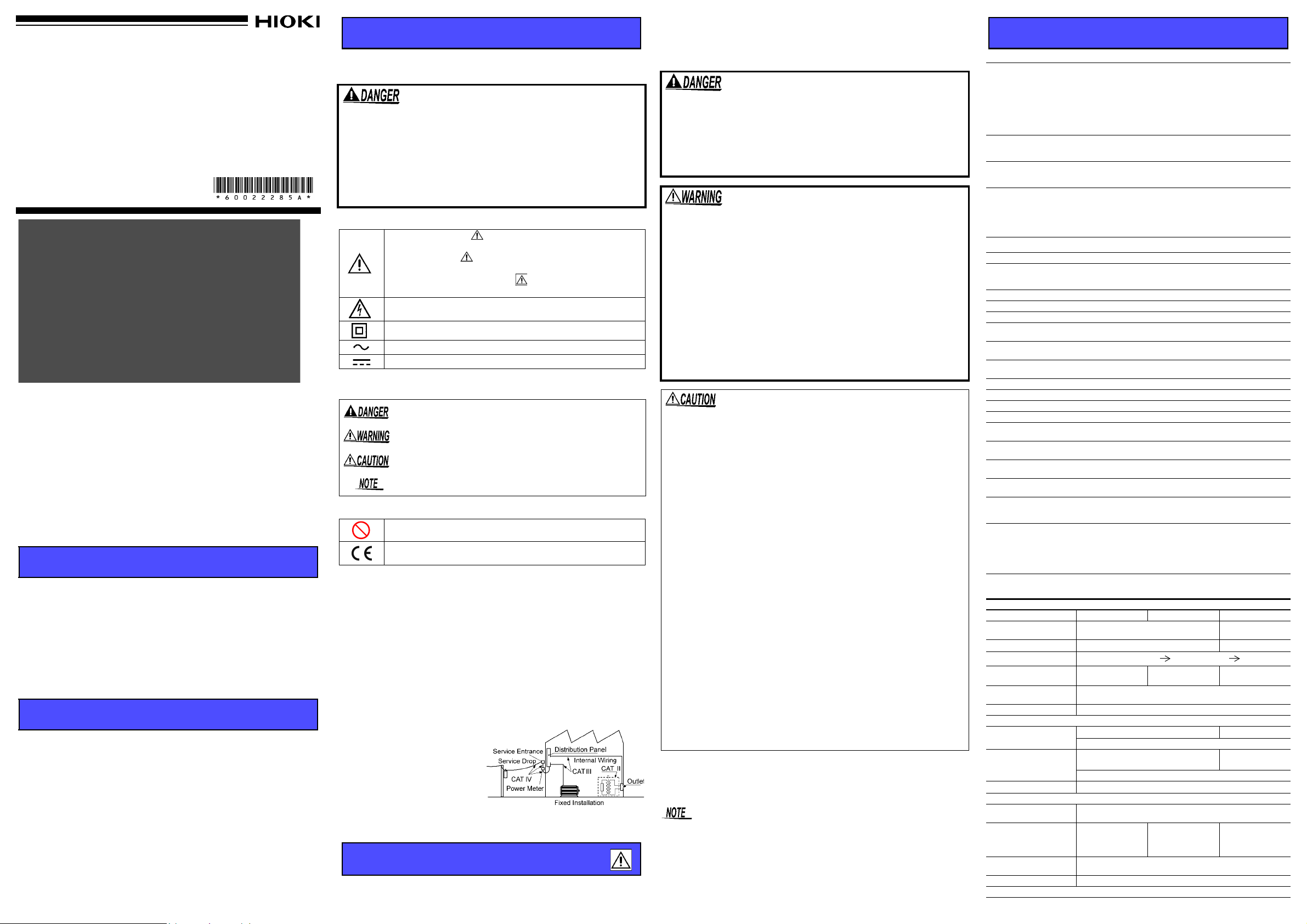
Measurement categories
This instrument complies with CAT III safety requirements.
To ensure safe operation of measurement instruments, IEC 60664
establishes safety standards for various electrical environments, categorized as CAT II to CAT IV, and called overvoltage categories. These
are defined as follows.
CAT II :Primary electrical circuits in equipment connected to an AC
CAT III:Primary electrical circuits of heavy equipment (fixed installa-
CAT IV:The circuit from the service drop to the service entrance, and
Using a measurement instrument in an environment designated with a higher-numbered
category than that for which the
instrument is rated could result in
a severe accident, and must be
carefully avoided.Use of a measurement instrument that is not
CAT-rated in CAT II to CAT IV
measurement applications could result in a severe accident, and must
be carefully avoided.
electrical outlet by a power cord (portable tools, household
appliances, etc.). CAT II covers directly measuring electrical
outlet receptacles.
tions) connected directly to the distribution panel, and feeders
from the distribution panel to outlets.
to the power meter and primary overcurrent protection device
(distribution panel).
Usage Notes
Follow these precautions to ensure safe operation and to obtain the full
benefits of the various functions.
Preliminary Checks
Before using the instrument the first time, verify that it operates normally to ensure that no damage occurred during storage or shipping. If you
find any damage, contact your dealer or Hioki representative.
• 1000 V or 600 V may be labeled depending on the supplied
test leads, but this is the rating of the test lead and not the
rating performance of the 3490. Please refer to the Specifications for the rating performance of this instrument.
• Before attaching to or removing the test lead from the
instrument, please remove the Test Lead from the tested
objected and turn the function switch to OFF.
• Do not use the instrument where it may be exposed to corrosive or combustible gases. The instrume nt may be damaged or
cause an explosion.
• Do not use the instrument where it may be exposed to oil,
chemicals, or solvents. Contact with these substances may
cause cracking in the instrument, resulting in damage or electric shock.
• Do not allow the instrument to get wet, and do not take measurements with wet hands. This may cause an electric shock.
• Please only use batteries for electrical supply. Any other electrical supply may damage the instrument and tested object
and cause electric shock.
• Before using the instrument, make sure that the insulation on
the test leads is undamaged and that no bare conductors are
improperly exposed. Using the instrument in such conditions
could cause an electric shock, so contact your dealer or Hioki
representative for replacements.
• This instrument is designed for use indoors. It can be operated at
temperatures between 0 and 50°C without degrading safety.
• Do not store or use the instrument where it could be exposed to direct sunlight, high temperature or humidity, or condensation. Under
such conditions, the instrument may be damaged and insulation
may deteriorate so that it no longer meets specifications.
• T o prevent accidents, please use the supplied L9787 Test Leads (or
the optional L9788-10).
• To avoid damage to the instrument, protect it from physical shock
when transporting and handling. Be especially careful to avoid physical shock from dropping.
• If the protective functions of the instrument are damaged, either remove it from service or mark it clearly so that others do not use it inadvertently.
• Although this instrument is dust resistant, it is not completely dustor waterproof. To prevent possible damage, avoid using in dusty or
wet environments.
• The protection rating for the enclosure of this device (based on
EN60529) is *IP40.
• Removable sleeves are attached to the metal pins at the ends of the
test leads. T o prevent a short circuit accident, be sure to use the test
leads with the sleeves attached when performing measurements in
the CAT III measurement category. Remove the sleeves from the
test leads when performing measurements in the CAT II measurement category. For details on measurement categories, see “Measurement categories” in the instruction manual.
• When performing measurements with the sleeves attached, be careful to avoid damaging the sleeves. If the sleeves are inadvertently
removed during measurement, be especially careful in handling the
test leads to avoid electric shock.
• To prevent an electric shock accident, confirm that the white or red
portion (insulation layer) inside the cable is not exposed. If a color
inside the cable is exposed, do not use the cable.
*IP40
4: Protected against access to hazardous parts with wire measuring 1.0 mm in diameter.
The equipment inside the enclosure is protected against entry by solid foreign objects
larger than 1.0 mm in diameter.
0: The equipment inside the enclosure is not prot ected against the har mful ef f ects of water.
• To avoid battery depletion, turn the function selector OFF after use. Battery
may drain if the switch is not turned to OFF.
• The test lead plug comes with a protective cap. Please remove this cap
before attaching it to the instrument.
• After measurement, please turn the function switch to OFF. The cover will not
close if the switch is not at OFF.
Specifications
Standard Specifications
• Insulation Resistance
DC voltage supply, current detection
• Low resistance measurement:
Functions
Automatic electric discharge
Auto Power Save
Indicator
DC current supply, voltage detection
• AC Voltage measurem ent : Average responding type
• Effective battery range indic ator: Built-in battery power in dicator
• Live circuit indicator: lights up when voltage is detected
between LINE terminal and EARTH terminal
Automatically discharges the electric charge still present in
the capacitance of the test object after the Insulation resistance measurement test.
When the function switch is not at OFF, the power will only
go off automatically 15 minutes after the last live circuit
alert has been displayed.
Indicator: Meter (Internal magnet type taut band method)
Indicator light
• Light device: LED
• Light automatic OFF function: Light goes off about 3 minutes after MEASURE key is switched to OFF or when
LIGHT key is pressed.
General Specifications
Guaranteed accuracy period 1 year
Operating Temperature &
Humidity
Operating Environment Indoors, Pollution Degree 2, Altitude up to 2000 m (6562-ft.)
Storage Temperature &Humidity 0 to 50C (32 - 122F), 90%RH or lower (non-condens ating )
Degree of protection IP40
Maximum rated voltage to
terminal
Maximum rated voltage to
earth
Dielectric strength
Power source Rated power voltage: 1.5 V DC × 4, LR6 alkaline battery × 4
Maximum rated power 3 VA
Continuous operating time Approx. 20 hours (at 500 V range, no load)
Drop Proof On concrete: 1 m/1 time
Dimensions
(excluding protrusions)
Mass
Accessories
Replacements
Options
Standards
0 to 40C (32 - 104F), 90%RH or lower (non-condensating)
40 to 50C
linear decrease up to 50%
600 V AC (AC voltage function)
600 V AC, Measurement Category III,
Anticipated Transient Overvoltage: 6000 V
7060 V AC, 50 Hz/60 Hz, Measurement terminals - electri-
cal enclosure, during 1 minute, current sensitivity 1 mA
Approx. 159W×177H×53D mm (6.26”W×6.97”D×2.09”D)
Approx. 610g (21.5oz)
(including battery, not including test lead)
L9787 Test Lead, Instruction manual, Shoulder strap,
LR6 alkaline battery × 4
FF0.5AH/ 1000 V (70 172 40.0.500: SIBA) (Very fast act-
ing, arc extinction type, high rupturing capacity type)
L9788-10 Test Lead with Remote Switch (Red)
L9787-91 Breaker Pin, L9788-92 Breaker Pin,
9804-02 Magnetic Adapter
Safety EN61010
EMC EN61326
Measuring equipment for Low voltage distribution system
EN61557-1/-2/-4* (the 3
*Subclause 4.3 of Part 4 (Interchanging of te st leads) is not
applicable when the L9788-10 is used.
(104 - 122F)
Measurement functions
Guaranteed for one year at 23C±5C (73F ±9F) and 90% RH.
Insulation Resistance Me as u r ement
Rated output voltage 250 VDC 500 VDC 1000 VDC
Effective maximum
indicated value
Center scale value
Response time
Possible number of
measurements
Effect of position
(Horizontal ±90)
Overload protection 660 VAC (10 sec.)
Accuracy
1st effective
measuring range
2nd effective
measuring range
0 M,
scale
Measurement terminal voltage characteristic
Open circuit voltage
(when no load is applied)
Lower limit measurement
resistance value to be
maintained rated
output
voltage
Rated current
Short circuit current 1.2 mA max.
Effect of temperature
1000 times
(at 0.25 M
0.25 M 0.5 M 1 M
1 mA (Tolerance: 1 to 1.2 times of the rating value)
(The current flow when rated
100 M
Within 3 sec. (
0.05 to 50 M
0.01 to 0.05 M
50 to 100 M
1 to 1.2 times of rated output voltage
measurement:
, at 50C and below relative with
RH
is applicable to part 4)
4000 M
50 M
1M
center value, 0 M)
1000 times
(at 0.5 M
±2% of scale length
2 to 1000 M
±2% of scale length
±2% of scale length
±2% of scale length
output
1000 to 4000 M
voltage is maintained)
1000 times
(at 1 M
0.5 to 2 M
Page 2
1st effective
2
1
3
4
5
6
7
8
9
10
11
12
13 14
15
15
15
16
15
17
17
1.Turn the function switch to OF F and
remove the test lead from the
instrument as a precaution.
2. Loosen the central fastening screw
at the back of the instrument and
remove the battery cover.
3.Replace all 4 batteries or the fuse.
4.Place back the battery cover and
tighten the screw.
Screw
Battery cover
Attaching the strap
Pass the ring on both
ends of the supplied
strap through each of
the four holes in the
instrument.
Source
(primary side)
Load
(secondary side)
Always turn off the breaker
or the measurement line.
OFF
Source
(primary side)
Load
(secondary side)
Do not press the
MEASURE key.
ON
the secondary side of the breaker.
Always connect the test lead to
Earth
electrode
measuring range
2nd effective
measuring range
, scale
0 M
Resistance Measurement
Ranges
Effective maximum
indicated value
Center scale value
Measuring range
Accuracy
Open-circuit voltage
Measuring current 200 mADC or more 20 mADC or more
Possible number of
measurements
(5sec ON, 25sec OFF)
Effect of temperature
Effect of position
(Horizontal ±9 0
Overload protection 720 VAC (10 sec., by Fuse)
AC Voltage Measurement
Measuring range 0 to 600 V
Accuracy
Frequency range 50/60 Hz
Input resistance 100 k or more (50Hz/60Hz)
Effect of temperature
Effect of position
(Horizontal ±9 0
Overload protection 660 VAC (10 s)
• Effect of temperature is applicable to the temperature range other than 18 to 28C
• Accuracy for the low resistance measurement is applica ble after zero adjustment (when
the temperature changes more than ±1C after zero adjustment, another zero adjustment is necessary)
• Accuracy is applicable after adjustment by meter movement zero adjuster
)
)
30
3
30
3
1.5
0 to 3
±0.09 ±0.9
1000 times
(at 1
±1.5% of scale length
±1.5% of scale length
±1.5% of scale length
15
0 to 30
4.1 to 6.9 V
±3% of effective maximum scale value
±3% of effective maximum scale value
±5% of maximum scale value
±5% of maximum scale value
±2% of maximum scale value
1000 times
(at 10
Names and Functions of Parts
□ L9788-10 Test Lead with Remote Switch (Red) (1.2 m)
Test lead with MEASURE key for the line side
measurement. Measurement can be started by pressing
the key. There is a ligh t at th e ti p which can be swit ch ed on
by pressing the LIGHT key on the 3490. Earth side lead is
not attached.
□ 9804-02 Magnetic Adapter
(Ø11 mm Corresponding standard screw: M6 Button head
screw)
Adaptor for connecting a Test lead to the round head screw
by means of magnetism.The tip of adaptor is a concave
shape in order to fit the round head screw.
Put an adaptor on the tip of the earth side lead of a L9787
Test Lead or L9788-11 Test Lead Set with Remote Switch
Replacing of Batteries and
Fuses
• To avoid electric shock, turn off the function switch and disconnect the test leads from the obje ct to b e measur ed, be fore
replacing the batteries or fuse.
• To avoid electric shock, turn off the MEASURE key and disconnect the test leads before replacing the batteries or fuse.
• After replacing the batteries or fuse, place back the cover and
tighten the screws before using the instrument.
• Do not mix old and new batteries, or different types of batteries. Also, be careful to observe battery polarity during installation. Otherwise, poor performance or damage from battery
leakage could result.
• Battery may explode if mistreated. Do not short-circuit,
recharge, disassemble or dispose of in fire.
• Handle and dispose of batteries in accordance with local regulations.
• Please use only the specified fuse. Specified fuse can be purchased, so contact your dealer or Hioki representative. Using
a non-specified fuse or shorting the fuse holder may cause a
life-threatening hazard.
Fuse type: FF0.5AH/ 1000 V (70 172 40.0.500: SI BA )
Fuse can be purchased from your Hioki distributor.
• To avoid corrosion from battery leakage, remove the batteries from the instrument if it is to be stored for a long time.
• Please use only alkali battery. Please do not use manganese, nickel-metal
hydride or Oxyride batteries.
(Very fast acting, arc extinction type, high rupturing capacity type)
battery range indicator. Battery power is high when a green light is
shown. Battery power is low when a red light is shown and replacement is recommended. Battery is drained when no light is shown.
Please replace the batteries then.
• Auto power save (power-saving function)
When the function switch is not at OFF , the power save function automatically
kicks in 15 minutes after the last time the MEASURE key is pressed and the
effective battery range indicator goes off. The automatic power save function
cannot be cancelled.
Reviving from power save
Turn off the function switch then return to the original position.
• Insulation Resistance Measurement
Observe the following to avoid electric shock, short circuits,
and damage to the instrument.
• When measuring insulation resistance, dangerous voltage is
applied to the measurement terminals. To avoid electric
shock, do not touch the probe.
• Never touch the object being measured immediately after
measuring. There is danger of electric shock from the charge
accumulated during high voltage testing.
• Discharge the subject conductor after measurement.
• Do not attempt to measure insulation resistance on a live
conductor. Doing so could damage the instrument or cause
an accident that might result in injury or death. Always turn
off power to the conductor being measured before starting.
• Insulation resistance is the ratio of leakage current to applied voltage, and is
therefore unstable. Depending on the specific object being measured, the
needle may not stabilize, but this is not a meter malfunction.
• Press the MEASURE key fully down until a click is heard. If the button is not
pressed down fully, the needle will not move from and a proper measurement cannot be made.
• Always release the MEASURE key after use.
1.Use the function switch to select the measurement voltage.
2. Connect the black test lead to the ground side of the object being
measured.
3.Connect the red test lead to the line to be measured.
4.Press the MEASURE key. (To make continuous measurements, pull
the button up.)
5.Read the value after the needle has stabilized.
1.Use the function switch to ~V (ACV).
2. Connect the black test lead to the ground side of the object being
measured.
3.Connect the red test lead to the line to be measured.
4.Read the value after the needle has stabilized.
• Low Resistance Measurement
Do not measure under a live circuit condition.
Before measuring, zero adjustment to cancel the test lead wiring resistance, etc. is necessary.
1.Turn the function switch to either 3 or 30 .
2.Short circuit the tip of the test lead.
3.Pull up the MEASURE key.
4. Turn the 0 AJD knob and adjust the needle until it points to the
center part of 0 of the low resistance scale. (Adjust to 0 , including the test lead line resistance for external resistance connected
directly to the test object.) Push down the MEASURE key.
5. Connect the test lead to the ground side of the object b eing measured.
6.Press the MEASURE key and read the indicated value.
7.Turn off the MEASURE key after using.
• Example of measuring the earthing conductor resistance
If an additional operating circuit is connected in parallel to the circuit
under measurement, the measurement error may occur due to the
effects of impedance of the circuit connected in parallel or transient
currents.
Measure the earthing conductor resistance at 3 range. Please refer
to the low resistance measurement for measuring method.
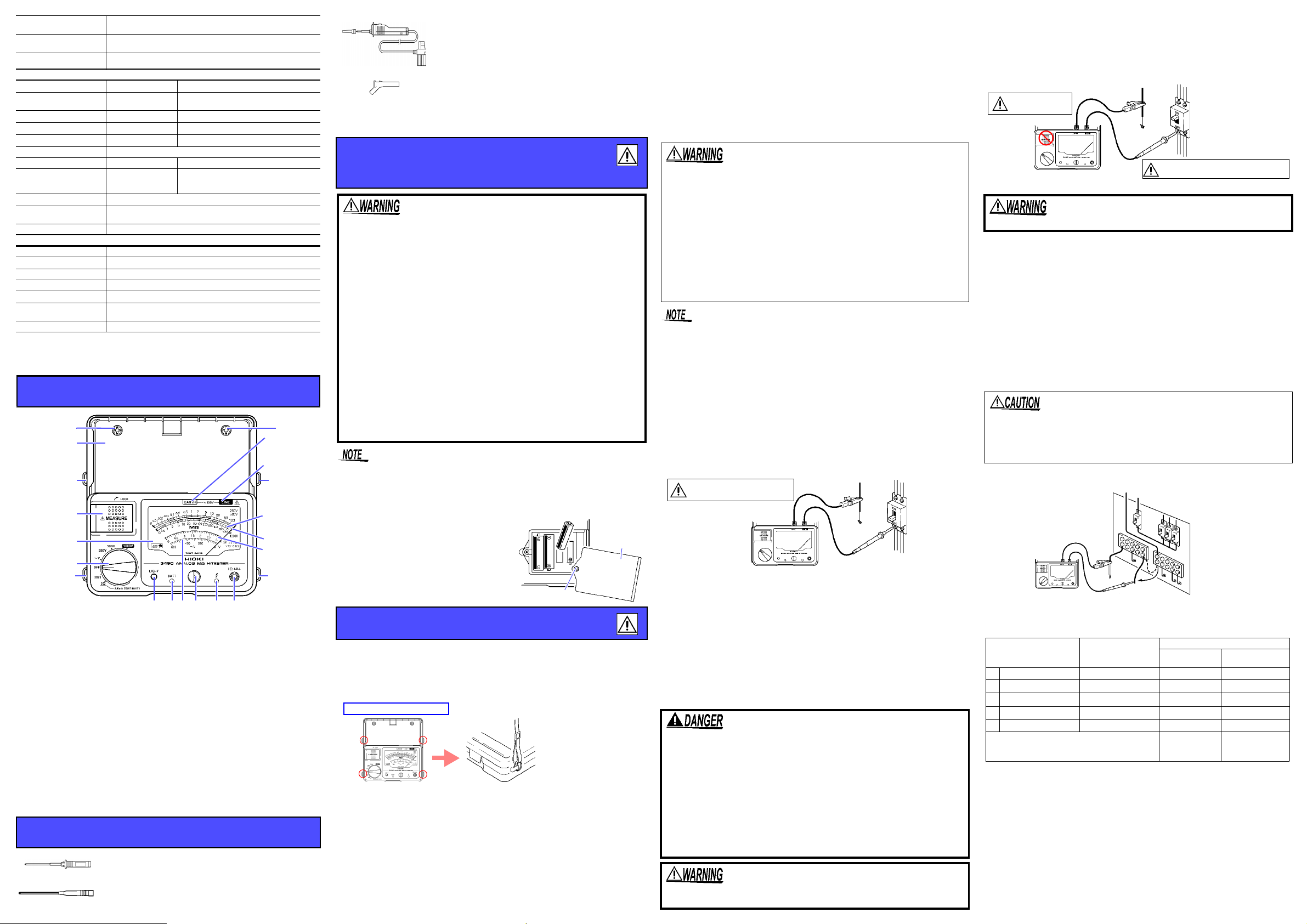
1. Function switch: Select measurement functions
2. MEASURE key: Press to measure insulation resistance or low resistance.
3. LIGHT key: Press this key to turn on the light
4. 0 ADJ Knob: Use in zero adjustment before low resistance measurement
5. Scale plate
6. Insulation resistance scale: Read blue scale at 250 V, 500 V and red scale
at 1000 V
7. Low resistance scale: Read as it is at 3 and multiply by 10 at 30
8. AC voltage scale
9. Indicator needle
10.Meter movement zero adjuster
11.EARTH terminal: Connect the black test lead
12.LINE terminal: Connect the red test lead
13.Effective battery range indicator: Green when battery power is high, red
14.Live circuit indicator: Lights up when voltage remains betwe en inp ut term inals
15.Strap opening: Pass the supplied strap through the opening
16.Test lead storage space: Stores the test lead without having to remove it
17.Sleeve stand: Attach the sleeve removed from the tip of the test lead.
when batter power is decreasing and no light when battery is drained
from the measurement terminal
Options
□ L9787-91 Breaker Pin
□ L9788-92 Breaker Pin
(Pin length 70 mm and 48 mm from the tip has width 2.5
mm. The rest have width 3.8 mm.) Breaker pin for L9787.
(Pin length 123 mm and 65 mm from the tip has width 2.6
mm. ) Breaker pin for L9788-10.
Measurement Procedures
Preparing for Measurement
1.Attach the strap.
2.Insert the batteries.
3.Connect the test lead (connect the black test lead to the EARTH terminal, and the red test lead to the LINE terminal)
Pre-measurement inspection
• Adjust the needle to point to zero before measuring. With the function
switch at OFF, turn the meter movement zero adjuster with a screw
driver until the needle points to the center part of the in the scale.
• Verifying the solid connection and integrity of the test leads
1.Turn the function switch to one of the Insulation Resistance Mea-
surementfunctions.
2.Short circuit the tips of the test leads.
3.Push down the MEASURE key, and confirm that the needle is
pointing to 0 M.
• Confirming the battery power
Set the function switch away from OFF and confirm the effective
*When measuring an insulation resistance that contains a ca-
pacitance element, a charge proportional to the measurement
voltage accumulates, and if undischarged could lead to an
electric shock accident.
6.Without removing the test leads from the item being measured,
release the MEASURE key.
7.The built-in discharge circuit automatically discharges the item. During a discharge, the needle will return slowly to the infinity (
) posi-
tion.
8.The discharge is completed when the needle reaches the . The time
required for discharge depends on the capacitance value.
• AC Voltage Measurement
• Test leads should only be connected to the secondary
side of a breaker, so the breaker can prevent an accident if a short circuit occurs. Connections should never
be made to the primary side of a breaker, because unrestricted current flow could cause a serious accident if a
short circuit occurs.
• Attempting to measure voltage in excess of the maximum input voltage and maximum rated voltage to earth
could destroy the instrument and result in personal
injury or death.
• To avoid electrical shock, be careful to avoid shorting
live lines with the test leads.
Never press the MEASURE key while measuring voltage. Doing so
could damage the circuitry or cause a life-threatening accident.
• Operation Uncertainty
The operation uncertainty and the variations of measurement value for
the respective Influence quantity approved by EN61557 are as follows:
Intrinsic uncertainty/
Influence quantity
A Intrinsic uncertainty Reference condition ±2 % ±3%
E
E
E
B
Influencing factor non-applicable for E4 to E
Position Hori zontal ±90 ±2% ±3%
1
Supply voltage 4.5 V to 6.8 V ±1% ±3%
2
Temperature 0C to 35C±1.5% ±3%
3
Operation uncertainty
Guaranteed range of operation uncertainty
Operation range
Insulation
Resistance
1st effective
measurement
10
Variation
Low
Resistance
±8% ±9%
0~ effective
range
maximum scale
value
• Measurement principles
1.Insulation Resistance Measurement
The insulation resistance of test object Rx is obtained by supplying a voltage V
to the test object and measuring the current leaking from the test object and the
voltage supplied using the formula (Voltage supplied, V)/(current leakage, l).
2.AC Voltage Measurement
This is obtained from converting the value of the current flowing from the
voltage source through the instrumen t to a vo ltage value.
3.Low Resistance Measurement
The resistance of test object Rx is obtained by supplying a specific current l to
the test object and measuring the voltage occurring between the test terminals
using the formula (inter-terminal voltage, V)/(su pplie d curren t l).
 Loading...