

Page 1
Feb. 2015 Edition 1
Printed in Japan
3481D980-00 15-02H
3481-20
VOLTAGE
DETECTOR
INSTRUCTION MANUAL
EN
Ideal for 100 V to 120 V installations.
Model 3481-20
Visual and audible
voltage detection indication
Auto Power OFF
Sensitivity-adjustable
×
Voltag e detection is not
○
performed properly.
it is parallel to the object.
Position the detecting element so that
Performance Check
Detection
The
white LED is still lighting up.
OK
OK
NG
2. Turn the switch ON.
Turn on the switch. In the state that the white LED is
lighting up, apply the detecting element t o the object t o
be detected. If there are several wires, conduct a voltage check of each wire separately. (Check some point s
for bundle of wires.)
The object cannot perform voltage detection. (It is not live or the earth potential is
below the Operating-voltage range)
The white LED lights up. The white LED does not light up or is dim.
The batteries are running
The red LED
flashes
and the buzzer sounds.
The red LED does not flash
or the buzzer does not so und.
The
instrument
is operating
The instrument may be malfunctioning.
properly. It can be used.
Do not use it.
The red LED flash and t he b uzzer sounds .
The object is live.
Switch
1. Inspect the instrument carefully to ensure that no damage.
There is no damage. The instrument is damaged.
Be sure to check the following before and after use to avoid
Contact your dealer or Hioki representative.
OK
NG
The red LED and buzzer
sound are getting off.
low. Replace the batteries.
NG
NG
The batteries are running
low. Replace the batteries.
3. Grip the instrument firmly and apply the
detecting element to a known power supply
(e.g., AC outlet) in order to check the
performance.
electrical shock.
Introduction
Thank you for purchasing the HIOKI “Model 3481-20 VOLTAGE DETECTOR.” To obtain maximum performance from the instrument, please read
this manual first, and keep it handy f or future refer ence.
Overview
This non-contact type of voltage detector unit enables the hot-line state of
AC voltage to b e che cked through the wire or c able covering.
Initial Inspection
When you receive the instrument, insp ect it carefully to ensure t hat no damage occurred during shipping. If damage is evident, or if it fa ils to operate ac-
cording to the specifications , contac t your deale r or Hioki repr esent ativ e.
Maintenance and Service
• To clean the instrument, wipe it gently with a soft cloth moistened
with water or mild detergent. Never use solvents such as benzene,
alcohol, acetone, ether, ketones, thinners or gasoline, as they can
deform and discolor the case.
• If the instrument seems to be malfuncti oning, co nfirm that the batt eries are not discharged, before contacting your dealer or Hioki representative.
Safety
This manual contai ns in format ion and warni ngs ess ential for s afe op eratio n
of the instrument and for maintaining it in safe operating condition. Before
using it, be sure to carefully read the fo llowin g safety prec auti ons.
This instrument is designed to comply with IEC 61010
Safety Standards, and has been thoroughly tested for safety
prior to shipment. However, mishandling during use could
result in injury or death, as well as damage to the instrument. Be certain that yo u understand the instructions an d
precautions in the manual before use. We disclaim any
responsibility for accidents or injuries not result in g dir ect ly
from instrument defects.
Safety Symbol
In the manual, the symbol indicates particularly important information that the user should read before using the instrument.
The symbol printed on the instrument indicates that the user
should refer to a corresponding topic in the manual (marked with the
symbol) before using the relevant function.
Indicates a double-insulated device.
Indicates AC (Alternating Current).
Indicates DC (Direct Current).
The following symbols in this manual indicat e the relative import ance of cautions and warnings.
Indicates that incorrect operation presents an extreme hazard
that could result in serious injury or death to the user.
Indicates that incorrect operation presents a significant hazard
that could result in serious injury or death to the user.
Indicates that incorrect operation presents a possibility of injury
to the user or damage to the device.
Indicates advisory items related to performance or correct operation of the instrument.
Symbols for Various Standards
Indicates the Waste Electrical and Electronic Equipment Directive
(WEEE Directive) in EU member states.
Indicates that the product conforms to regulations set out by the EC
Directive.
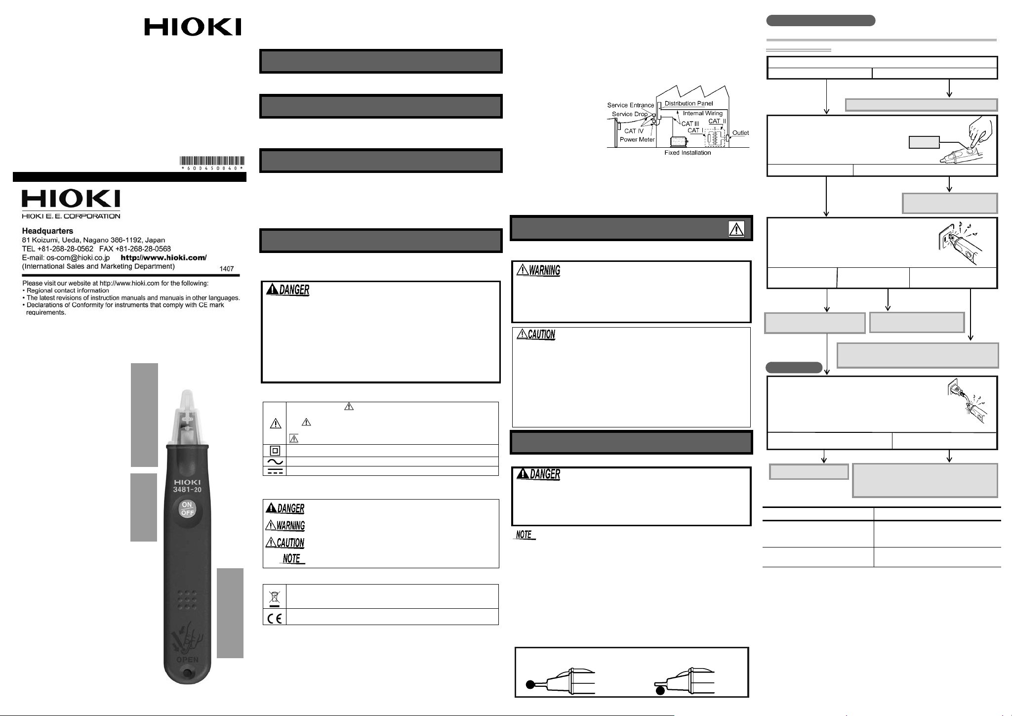
Measurement categories (Overvoltage categories)
This instrument complies with CAT IV (600 V) safety requirement s.
To ensure safe operation of measurement instruments, IEC 61010
establishes safety standards for various electrical environments,
categorized as CAT I to CAT IV, and called measurement categories. These are defined as follows.
CAT I: Secondary electrical circuits connected to an AC electrical
outlet through a transformer or similar device.
CAT II: P rimary electrical circuits in equipment conn ected to an AC
electrical outlet by a power cord (portable tools, household appliances, etc.)
CAT III:Primary electrical circuits of heavy equipment (fixed installations) connected directly to the distribution panel, and feeders
from the distribution panel to outlets.
CAT IV: The circuit from the service drop to the service entrance,
and to the power meter and primary overcurrent protection device
(distribution panel).
Higher-numbered categories correspond to electrical environments with
greater momentary
energy. So a measurement device designed for
CAT III environments can
endure greater momentary energy than a device
designed for CAT II.
Using a measurement instrument in an environment designated
with a higher-numbered category than that for which the instrument is rated could result in a severe accident, and must be carefully avoided. Never use a CAT I measuring instrument in CAT II,
III, or IV environments. The measurement categories comply with
the Overvoltage Categories of the IEC60664 Standards.
Usage Notes
Follow these precautions to ensure safe oper ation and to obtain the
full benefits of the various functions.
This instrument is measured on a live line. To avoid electric shock when measuring live lines, wear appropriate
protective gear, such as insulated rubber gloves, boots
and a safety helmet.
• This instrument is designed for use indoors. It can be operated at
temperatures between 0 and 40°C without degrading safety.
• This instrument is not designed to be entirely water- or dust-proof.
Do not use it in an espe cially dusty envi ronmen t, nor wher e it mi ght
be splashed with liquid. This may cause damage.
• To avoid damage to the instrument, protect it from physical shock
when transporting and handling. Be especially careful to avoid
physical shock from dropping.
• Do not look directly into the penlight nor shine the light at another
person's eye. Doing so may cause damage to the eye.
Detection
Performance Check and Voltage Detection
The maximum rated voltage between input terminals and
ground is 600 V AC. Attempting to measure voltages
exceeding 600 V with respect to ground could damage
the instrument and result in personal injury.
• The white LED indicates battery consumption but is not a guarantee
of the performance of the instrument. Be sure to check its performance using a known power source (e.g., AC outlet) prior to use.
• The instrument voltage detector works using a live AC circuit. It will
not work using an earthed wire or neutral point. If there are several
lines, such as 2-phase wires and 3-phase wires, perform voltage
detection on each line separately.
• The instrument cannot perform voltage detection on a shielded wire.
• Be sure to grip the instrument firmly during measurement. But, do
not touch the portion beyond the barrier. It will not produce any
detection.
• Make sure the detecting element properly contacts the object to be
measured. (See the below figure.)
VOL TAG E DE TE CT OR Object to be Me asur ed
The white LED still lighting up, and
the red LED flashes and the buzzer
sounds.
Only the white LED lights up.
Live.
Not live or below the Operating-voltage
range.
Page 2
The sensitivity will vary according to wire types or operating
Adjusting sensitivity
1.Slide the battery cover to the position where the sensitivity adjustment
trimmer appears.
2.Turn the trimmer with a precision screwdriver to adjust the sensitivity ,
placing the detecting element into contact with an object to be
detected.
1
2
Sensitivity
adjustment
trimmer
Clockwise:
Increase the sensitivity to detect a relat ively low volt age.
Counterclockwise:
Decrease the sensitivity to detect a rel atively high volt age
1
2
3
Turn the switch off.
Replace the old batteries with new
4
ones. Confirm correct polarity when
installing the new batteries.
Unlock the battery cover by pressing in
the opening with the tip of a pen,
screwdriver or other thin apparatus and
slide the cover towards the end of the
Slide the battery cover back
into locked position.
voltage detector.
Replacing the batteries
①
②
Barrier
Detecting
element
Switch
Model 3481-20
environments. Please adjust the sensitivity appropriately
depending on your operating environment.
Replacing the batteries
• Do not mix old and new batteries, or different types of batteries. Also, be careful to observe battery polarity during
installation. Otherwise, poor performance or damage from
battery leakage could result.
• Battery may explode if mistreated. Do not short-circuit,
recharge, disassemble or dispose of in fire.
• Handle and dispose of batteries in accordance with local
regulations.
• Keep batteries away from children to prevent accidental
swallowing.
• Use LR44 button alkaline battery.
• After use, alway s turn OFF the power to prevent battery drain.
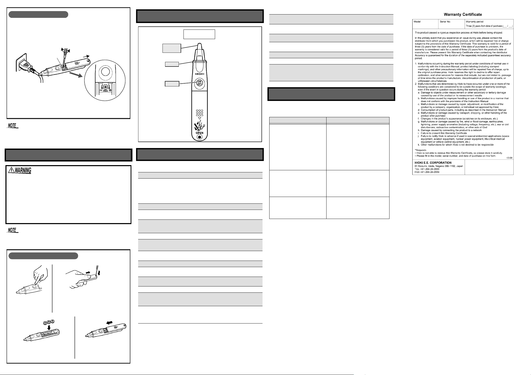
Name of Parts
Specifications
Basic Specifications
Function Detection
40 to 600 V AC
(When brought into contact with a 2-mm
Operating Voltage Range
Operating frequency 50 Hz/60 Hz
Pilot light
Additional Functions
Power supply Three LR44 button alkaline batteries.
Dimensions
Mass
Operating environment Indoors, altitude up to 2000 m (6562 ft.)
Operating temperature and
humidity
Storage temperature and
humidity
Product warranty period 3 years
Accessories
Standards Safety
lated cable equivalent to 600 V polyvinyl chloride insulated wire )
Maximum sensitivity variable range
40 to 80 V AC
flashes
The red LED
when the wire is live.
Light
Battery check (The white LED is dim or out
when the batteries are low.)
Approx. 20W× 126H × 15D mm (0.79”W ×
4.96”H × 0.59”D)(excluding projections)
Approx. 30 g (1.1 oz.)
(including three LR44 button alkaline batteries)
0°C to 40°C (32
(no condensation)
-20°C to 60°C (-4°F to 140°F), 80%RH or less.
(no condensation)
Instruction manual
Three LR44 button alkaline batteries
(Installed in the instrument, for operation check)
EN61010, Pollution degree2,
Measurement category IV 600 V
(anticipated transient overvoltage 8000 V)
EN61326
EMC
and the buzzer sounds
°F
to 104°F), 80%RH or less.
2
insu-
Electrical Specifications
Maximum rated voltage
to earth
Dielectric strength
Rated supply voltage
Operating supply-voltage range
Maximum rated power 550 mVA (Max.)
Continuous operating time Approx.5 hours (Power ON Standby state)
Auto power off
600 V AC
8.54 kV rms(between the detecting element
and main body)
1.5 V DC × 3
From 4.95 V to the voltage at which the white
LED goes out (central value: 3.6 V)
The power will be turned off automatically if
the instrument remains idle for 3 minutes after
the power is turned on. To reset, turn the
power on again using the Power ON switch.
If a malfunction is suspected
Although the following phenomena, which are unavoidable in the det ecti on
principle, can be ob ser ve d, t he instrument has no malfunction.
Phenomenon Cause
Even after the sensitivity adjustment or at a distance of tens of
millimeters from circuits, the instrument detects the live circuits
with a voltage of 200 V AC or
higher.
The instrument incorrectly detects metalware including steel
desks as live.
If the instrument is rapidly moved
closer to or away from non-live circuits or DC circuits, the instrument
detects live st at e te mp orar ily.
Model 3481-20 is intended mainly to
detect circuits with a volt age of 10 0 V
AC. The sensitivity variable range is
specified as from 40 V to 80 V AC in
consideration of safety. Thus, the instrument may detect circuits with a
voltage of 200 V AC or higher even
after the sens itivity adjus tment or a t a
distance from the circuit.
Metalware close to AC power may
charge AC potential (induced potential) to ground due to the influence of
electrostatic capacitance, resulting in
incorrectly detecting.
The non-live circuits or DC circuits
may charge static electricity, temporarily resulting in incor rectly detecting.
 Loading...