

Page 1

Instruction Manual
3470
MAGNETIC FIELD HiTESTER
December 2008 Revised edition 4 3470A981-04 08-12H
Page 2

Page 3

Contents
i
Contents
Introduction ................................................................................1
Inspection ..................................................................................2
Safety Information ................... .................... ................... ...........4
Operating Precautions ................. ................... .................... .......6
1Overview 9
1.1 Product Overview ...............................................9
1.2 Features ........................................................... 11
1.3 Measurement Example ....................................13
1.4 Names and Functions of Parts .........................17
1.4.1 3470 Magnetic Field HiTester ............................17
1.4.2 3471 Magnetic Field Sensor ..............................21
1.4.3 3472 Magnetic Field Sensor ..............................22
1.5 Definition of Measurement Items ......................23
1.6 Screen Configuration and Key Operation
Work Flow ........................................................24
1.7 Measurement Work Flow ................................. 27
2 Measurement Preparations 29
1
2
3
4
5
6
7
8
2.1 Supplying Power ..............................................29
2.1.1 Connecting the AC Adapter ..............................29
2.1.2 Inserting and Replacing Batteries ......................30
2.2 Connecting a Magnetic Field Sensor ...............32
2.3 Turning the Power On and Off .........................33
3 Measurement Procedure 35
3.1 Measurement Preparations ..............................3 5
3.2 Pre-measurement Check .................................37
3.3 Measuring Magnetic Flux Density .................... 38
3.4 Measuring Exposure Level (General Public) .... 41
10
11
APP
Index
Page 4

ii
Contents
3.4.1 Preparing for Exposure Measurements .............41
3.4.2 Exposure Level ..................................................43
3.4.3 Measurement Procedure ...................................45
3.5 Measuring Exposure Level (Occup.) ................ 48
3.6 Holding Maximum Value of the Resultant
RMS Values .....................................................51
3.7 Checking and Deleting Saved Data .................52
3.7.1 Checking Saved Data ........................................52
3.7.2 Deleting Saved Data ..........................................54
3.7.3 Deleting All Saved Data .....................................57
4 Advanced Functions 59
4.1 Checking Remaining Battery Power ................. 59
4.2 Function for Saving Settings (Saving Set
Modes and Measurement Ranges) .................. 60
4.3 Initializing Function (Returning Settings to
Their Factory Defaults) .....................................61
4.4 Other Functions ................................................62
4.4.1 Setting Auto Power Off (Sav ing Battery Power) 62
4.4.2 Setting Audible Key Feedback ..........................64
4.4.3 Changing Unit Indication ....................... ............66
4.4.4 Setting the Slow Function ..................................68
4.4.5 Turning on the MEM. MODE key in MAX.
HOLD or output mode .......................................70
5 Using Application Software 73
5.1 Overview ..........................................................73
5.2 Installing ........................................................... 74
5.2.1 Installing the Driver ............................................74
5.2.2 Installing software ..............................................82
5.3 Graphic Representation of Measurement
Values ..............................................................85
5.4 Transferring Recorded Data to a PC ................ 88
5.5 Configuring the 3470 ........................................91
Page 5

Contents
5.6 Viewing Version Information .............................93
6 Advanced Measurements 95
6.1 Outputting Waveform and Resultant
RMS Values .....................................................95
7 Specifications 101
iii
1
2
7.1 3470 Magnetic Field HiTester ........................101
7.1.1 Basic Specifications .........................................101
7.1.2 General Specifications .....................................103
7.1.3 Application Software ................................. .......104
7.1.4 Equations and Functions .................................105
7.2 3471 Magnetic Field Sensor ...........................107
7.3 3472 Magnetic Field Sensor ...........................108
8 Maintenance and Service 109
8.1 Troubleshooting ..............................................109
8.2 Error Indication ...............................................110
8.3 Version Display ..............................................110
8.4 Cleaning ......................................................... 110
8.5 Service ...........................................................110
Appendix 111
Appendix 1 ICNIRP Guideline (Basic Restrictions) ..111
Appendix 2 Coupling Factor in the ICNIRP
Guidelines .............................................112
Appendix 3 Graph Showing the Range of
ICNIRP 1998 Guidelines ....................... 113
3
4
5
6
7
8
10
11
APP
Index
Page 6

iv
Contents
Page 7
Introduction
Thank you for purchasing the HIOKI “Model 3470 Magnetic Field HiTester.” To obtain maximum performance from the instrument, please
read this manual first, and keep it handy for future reference.
1
Introduction
This instruction manual contains instructions for use of the device
with the3471 and 3472 Magnetic Field Sensor.
Note
While every effort has been made to ensure that the content of this manual is correct, we would appreciate it if you notified your dealer or local
Hioki agent should you notice any unclear, incorrect or missing informa
tion.
Trademarks in this manual
Microsoft, Windows, and Windows NT are registered trademarks of
Microsoft Corporation in the United States and/or other countries.
Notation
• Unless otherwise specified, “Windows” represents Windows 98, Me,
Windows NT, Windows 2000, Windows XP.
• Dialog box represents a Windows dialog box.
• Menus, commands, dialogs, buttons in a dialog, and other names on
the screen and the keys are indicated in brackets.
Mouse Operation
Click: Press and quickly release the left button of the mouse.
Right-click: Press and quickly release the right button of the mouse.
Double click: Quickly click the left button of the mouse twice.
Drag: W hile ho lding dow n the left button of the mouse, move the
Activate: Click on a window on the screen to activate that window.
mouse and then releas e the left button to deposit the chosen item in the desired position.
-
2
3
4
5
6
7
8
9
10
11
12
13
Page 8

2
Inspection
Inspection
Verifying Package Contents
When you receive the instrument, inspect it carefully to ensure that no
damage occurred during shipping. If damage is evident, or if it fails to
operate according to the specifications, contact your dealer or Hioki rep
resentative.
3470-01 Magnetic Fiel d HiTester
-
3470 (1) USB cable (1)CD (PC application
software) (1)
LR6 alkaline battery (4)
3471 Magnetic Field Sensor (1)
9445-02 AC Adapter
or
9445-03 AC Adapter (EU)
(1)
Carrying Case (1)
Instruction manual
(1)
Page 9

Inspection
3470-02 Magnetic Fiel d HiTester
3
3470 (1) USB cable (1)CD (PC application soft-
LR6 alkaline battery (4)
9758 Extention Cable
(1) 9759 Output Cable (1 ) Carrying Case (1)
ware) (1)
9445-02 AC Adapter
or
9445-03 AC Adapter (EU)
(1)
3471 Magnetic Field Sensor (1) 3472 Magnetic Field
Instruction man-
ual (1)
Sensor (1)
2
3
4
5
6
7
8
This instrument has been calibrated to operate with the provided sensor and should be used only with this sensor. Thus if multiple instruments are used, Before use make sure that the matching number (up
to the hyphen) on the tester and the sensor are identical.
Shipping precautions
Use the original packing materials when transporting the instrument, if
possible.
9
10
11
12
13
Page 10

4
Safety Information
Safety Information
This instrument is designed to comply with IEC 61010 Safety
Standards, and has been thoroughly tested for safety prior to
shipment. However, mishandling during use could result in injury
or death, as well as damage to the instrument. Be certain that you
understand the ins truct i ons and precautions in the manual before
use. We disclaim any responsibility for accidents or injuries not
resulting directly from instrument defects.
This manual contains information and warnings essential for safe operation of the instrument and for maintaining it in safe operating condition.
Before using it, be sure to carefully read the f ollowing sa fety precautions.
Safety Symbols
In the manual, the symbol indicat es p art icul ar ly im por tant information that the user should read before using
the instrument.
The symbol printed on the instrument indicates that
the user should refer to a corresponding topic in the manual (marked with the symbol) before using the relevant
function.
Indicates DC (Direct Current).
The following symbols in this manual indicate the relative importance of
cautions and warnings.
Indicates that incorrect operation presents an
extreme hazard that could result in serious injury or
death to the user.
Indicates that incorrect operation presents a significant hazard that could result in serious injury or
death to the user.
Indicates that incorrect operation presents a possibility of injury to the user or damage to the instrument.
Indicates advisory items related to performance or
correct operation of the instrument.
Page 11
Other Symbols
(⇒ p. )
*
5
Safety Information
Indicates the location of reference information.
Indicates that descriptive information is provided below.
Indicates a prohibited action.
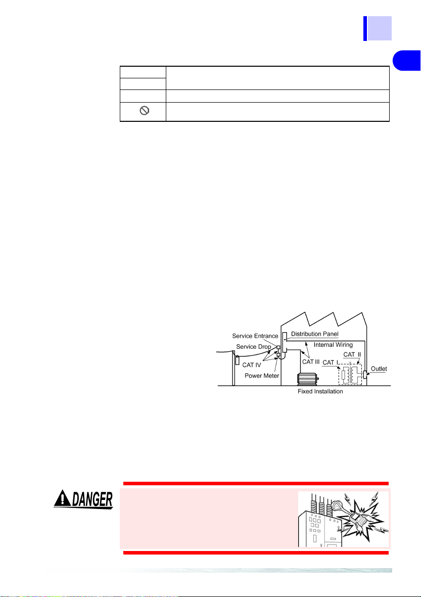
Measurement Categories (Overvoltage categories)
To ensure safe operation of measurement instruments, IEC 61010
establishes safety standards for various electrical environments, catego
rized as CA T I to C AT IV, and call ed measurement cat egories. The se are
defined as follows.
CAT I : Secondary electrical circuits connected to an AC electrical
CAT II : Primary electrical circuits in equipment connected to an AC
CAT III : Primary electrical circuits of heavy equipment (fixed installa-
CAT IV : The circuit from the service drop to the service entrance, and
Higher-numbered categories correspond to electrical environments with
greater momentary
energy. So a measure
ment device designed for
CAT III envir onment s can
endure greater momen
tary energy than a device
designed for CAT II.
Using a measurement instrument in an environment designated with a
higher-numbered category than that for which the instrument is rated
could result in a severe accident, and must be carefully avoided.
Never use a CAT I measuring instrument in CAT II, III, or IV enviro nment s.
The measurement categories comply with the Overvoltage Categories of
the IEC60664 Standards.
outlet through a transformer or similar device.
electrical outlet by a power cord (portable tools, household
appliances, etc.)
tions) connected directly to the distribution panel, and feeders
from the distribution panel to outlets.
to the power meter and primary overcurrent protection device
(distribution panel).
-
-
2
-
3
4
5
6
7
8
9
10
Do not touch high voltage lines with the
sensor or the instrument. They are not
insulated and the application of high volt
age to this instrument may expose testing
personnel to high voltage that may at
worst lead to electric shock and death.
-
11
12
13
Page 12

6
Operating Precautions
Operating Precautions
Follow these precautions to ensure safe operation and to obtain the full
benefits of the various functions.
Preliminary Checks
• Before using the instrument the first time, verify that it operates normally to ensure that the no damage occurred during storage or shipping. If you find any damage, contact your dealer or Hioki
representative.
• Before using the instrument, make sure that the insulation on the
cables is undamaged and that no bare conductors are improperly
exposed. Using the instrument in such conditions could cause an
electric shock, so contact your dealer or Hioki repr esent ative for rep air.
Installation Environment
Operating temperature/humidity range: 0 to 40°C, 80%RH or less
(no condensation)
Temperature and humidity for guaranteed accuracy: -10 to 50°C,
80%RH or less (no condensation)
Avoid the following locations that could cause an accident or damage to the instrument.
Exposed to direct sunlight
Exposed to high temperature
Exposed to liquids
Exposed to high humidity
or condensation
Exposed to high levels of
particulate dust
In the presence of corrosive or explosive gases
Exposed to strong electromagnetic fields
Near electromagnetic
radiators
Subject to vibration
Connections
Connect only designated devices to the instrument terminals. To prevent damage, do not apply a voltage that is outside the specified range
to the instrument.
Page 13

Handling
7
Operating Precautions
• The instrument and the 3471 and 3472 Magnetic Field Sensors are
built mainly from nonmagnetic metals and contain hardly any mag
netic materials. Thus if the inst rument is heated by an all metal IH and
other induction heating system the sensor may melt or be damaged,
because of the nonmagnetic metals.
• The 3471 and 3472 Magnetic Field Sensors have a plastic housing that
may melt if brought into contact with a hot measurement object (cookpot
or other hot object).
• Do not expose cables t o exces siv e str ess as they may br eak . Esp ec iall y,
the 9758 Exten tion Ca ble and 975 9 Output C able shou ld be hand led with
care.
Handling with the CD
• Always hold the disc by the edges, so as not to make fingerprints on
the disc or scratch the printing.
• Never touch the recorded side of the disc. Do not place the disc
directly on anything hard.
• Do not wet the disc with volatile alcohol or water, as there is a possibility of the label printing disappearing.
• To write on the disc label surface, use a spirit-based felt pen. Do not
use a ball-point pen or hard-tipped pen, because there is a danger of
scratching the surface and corrupting the data. Do not use adhesive
labels.
• Do not expose the disc directly to the sun's rays, or keep it in conditions of high temperature or humidity, as there is a danger of warping,
with consequent loss of data.
• To remove dirt, dust, or fingerprints from the disc, wipe with a dry
cloth, or use a CD cleaner. Always wipe radially from the inside to the
outside, and do no wipe with circular movements. Never use abra
sives or solvent cleaners.
• Hioki shall not be held liable for any problems with a computer system
that arises from the use of this CD, or for any problem related to the
purchase of a Hioki product.
-
-
2
3
4
5
6
7
8
9
10
11
12
13
Page 14

8
Operating Precautions
Page 15

1.1 Product Overview
Overview 1
1.1 Product Overview
The 3470 Magnetic Field HiTester is designed to measure magnetic flux
density and level of magnetic field exposure.
• It can be used to assess conformance to ICNIRP 1998 and EN50366
(IEC62233) and in research on magnetic field exposure.
• The instrument is designed to be used with the 3471 and 3472 Magnetic Field Sensors.
Make sure that the matching number (up to the hyphen) on the tester
and the magnetic field sensor are identical.
9
1
2
3
4
• Magnetic field exposure refers to the exposure that may affect human
health.
The 3470 Magnetic Field HiTester can be used to measure conformance to Guidelines for Limiting Exposure to Time-varying Elec-
tric, Magnetic, and Electromagnetic Fields (ICNIRP 1998) and a
standard for measuring magnetic fields of electrical household
appliances (EN50366).
For more information on ICNIRP: "Appendix" (P.111)
• This tester can measure magnetic flux density and magnetic field
exposure generated by products manufactured at a customer site or
produced by devices in a customer environment.
It can measure magnetic flux density and magnetic field exposure
generated by products manufactured at a customer site or produced
by devices in a customer environment.
5
6
7
8
9
10
11
12
13
Page 16

10
1.1 Product Overview
Functions Functions in detail Reference
Basic Magnetic flux
Application Output
density
measurements
Exposure
level
measurements
functions
Application
software use
*1: Available units are T, G, and A/m and the magnetic permeability of air being 4π×10-7 H/m,
*2: This value is obtained by inverse filtering of magnetic flux density values stated in
Measuring the magnetic flux density of appli-
*1
ances and environments
Magnetic flux density (10 Hz to 400 kHz):
For wide range measurement s of magne tic fl ux densit y
Magnetic flux density (10 Hz to 2 kHz):
For magnetic flux density of power frequencies
Magnetic flux density (2 kHz to 400 kHz):
For magnetic flux density of hig h frequencies other
than power frequencies
*2
Measuring the exposure level of appliances
and environmen t s
Exposure level (general public):
This level is used f or measuring exposur e to magnetic fields prevalent in environments where we can
assume the presence of people of all age groups and
health conditions (people who are not normally
aware of the presence of magne tic field s) as well as
exposure to magnetic fields gener ated by appli anc
es and other consumer devices manufactured to
conform to EN50366 (or IEC6233) and other st an
dards.
This level corresponds t o the general public exp osure level in ICNIRP 1998.
Exposure level (occupational):
This level applies to measurements of exposure to
magnetic fields in environments that involve
adults only who are generally exposed under
known conditions and are trained to be aware of
potential risk and to take ap propriate prec autions.
This level corres ponds to the occupational ex po
sure level in ICNIRP 1998.
A function that makes it possible to output
3.3 (P . 38)
3.4 (P . 41)
-
-
-
6.1 (P . 95)
3.5 (P . 48)
waveforms and resultant RMS value of magnetic flux density or exposure levels.
• This function allows you to do the following:
5 (P. 73)
• to set up the 3470 from your PC
• to upload data saved on the 3470 to your PC
• to monitor RMS values
4
the relationships between th e differ ent uni ts are as fol lows : 1T=10
the ICNIRP1998 Guideline.
Use the exposure level figures indicated for the general public in IEC62233 or Since
the reference levels for magnetic field exposure indicated in ICNIRP1998 for occu
pational exposure is approximately five times that of general public exposure, the indicated values for occupational exposure is roughly a fifth of general public exposure.
"Appendix" (P.111)
G, 1 A/m=4π×10-7 T.
-
How big is the magnetic field?
Page 17

1.2 Features
11
1.2 Features
Easy to view LCD displ ay
The large LCD display makes for ease of viewing measurement values.
Automatic recognition of magnetic field sensors
Two magnetic field sensors of different sizes, the 3471 and 3472, are
available for the tester
The 3471, inte nded fo r normal appli cation , has a cr oss- sectio nal a rea of
2
100 cm
The 3472 sensor has a cross-sectional area of 3 cm2 and is designed
for measuring d et a ile d di stri but ion .
The 3470 automatically recognizes an attached sensor so there is no
need to set a conversion rate whenever a sensor is connected.
Switchable measu re ment methods
The tester allows the user to switch between the following measurement
modes: magnetic flux density, exposure (General Public), and exposure
(Occup.).
Switchable axis
The user can switch between different axes (x-axis, y-axis and z-axis
and resultant values) in each measurement mode
.
3471
3472
1
2
3
4
5
6
7
8
9
Waveform and resultant RMS value output
Both waveform ( ) and resultant RMS ( ) output can be
selected.
With a 9759 Output Cable you can connect the 3470 to an oscilloscope
or recorder for output of waveforms and resultant RMS values.
Waveform output :
Resultant RMS
value output :
enables measurement of magnetic field waveforms when
the tester is connected to an oscilloscope or recorder.
permits recording of resultant values on a recorder or logger, which is convenient for long-term measurements.
10
11
12
13
Page 18

12
1.2 Features
Memory function
Records up to 99 measurement data.
Function for saving settings
Measuring conditions can be stored to enable quick access to the same
operating conditions each time you power up.
Dual power supply
The tester can be powered both by battery and AC power to enable
measurements in the field as well as permitting installation for long-term
measurements.
Page 19

1.3 Measurement Example
1.3 Measurement Example
This section provides a measurement example using this tester.
Objective: to measure magnetic field exposure generated by products to determine
whether they pass or fail the requirements to obtain a CE marking.
Measurement location : Anechoic chamber*1
Device under test : exposure level (general public) of magnetic
Measurement location, distance*2: around, 30 cm
State of device under test *2 : Half-filled with water, and maxiMeasurement time : a few seconds at each measurement point
fields generated by an electric rice cooker
*3
mum heat setting
DUT (device under test)
13
1
2
3
4
5
Be sure to measure areas that
generate maximum exposure to
magnetic fields.
In this example, r1 = 30 cm.
Storage of measurement data: tester memory and PC memory
Required equipment : 3470
*1: A location where magnetic fields other than that generated by the DUT is minimal
and where the re are no magnet ic fie lds or me tal ob jects in the vi cinity that c ould be
affected by the measurements. An anechoic chamber is not required if the above
conditions can be met.
Measurements performed in an anechoic chamber should be performed at a certain distance from the walls, which are made of a magnetic material.
*2 : Since this state depends on the DUT, refer to the IEC62233, EN50366 or other rel-
evant specifications to determine the required state of the DUT during testing.
*3 : This value comes from IEC62233 Ed.1.0. Note that it may change when the stan-
dard is revised.
3471 or 3472 sensor
Batteries
AC adapter
Product whose magnetic field is to be
tested
PC
6
7
8
9
10
11
12
13
Page 20

14
1
1.3 Measurement Example
Preparations
1. Insert batteries in the tester or connect it to the AC adapter and fold
out the stand. Also connect the 3471 or 3472 M agnetic Field Sensors.
Insert th e sensor in the sensor
terminal.
Plug the adapter into the AC
adapter terminal and the
mains plug into an AC wall
outlet.
Insert batteries in the battery
compartment on the rear and fold
out the stand.
2. Connect the tester to a PC using a USB cable.
USB cable
3. Install the driver and the PC software on the PC.
Page 21

15
2
3
1.3 Measurement Example
Setup, measurements and data storage
1. Select Exposure (general public) measurement mode.
2. Select Auto range. ([AUTO] on the display lights. )
3. Place the magnetic field sensor near the DUT. (A distance of 30 cm if
the DUT is an electric cooker)
Read the indicated value and press
to save the m easurement data.
4. Read the indicated value and store the measurement data in the
tester.
1
2
3
4
5
Processing data after measurement
1. Start up the software and transfer the measurement data stored in the
instrument to the PC.
2. Analyze the data transferred to the PC using Excel or other spreadsheet program.
6
7
8
9
10
11
12
13
Page 22

16
1.3 Measurement Example
Analysis flow chart
START
Measurement data ± accuracy
< 100%
*
Yes
≥100%
(Measurement data ± accuracy) ×
coupling factor (0 to 1)
≤100%*
Yes
≥100%
Exceeds
Does not comply
* : Whether tester accur acy sho uld be added or subt racted depen ds on th e sta ndpoint
of testing personnel. Refer to the instructions in the IEC62233 standards.
For details on the coupling factor, refer to Appendix 2 "Coupling Fa ctor in the ICNIRP Guidelines" (P.112).
*2 : This cannot be measured by a magnetic field tester.
Calculate the induced current
density with the human body
model and a numerical analysis.
Evaluation goes below the basic
restrictions.
Yes
Complies
Page 23

1.4 Names and Functions of Parts
1.4 Names and Functions of Parts
1.4.1 3470 Magnetic Field HiTester
17
1
Front
Display
(P. 20)
AC adapter terminal
Connect the AC adapter here.
2.1.1 (P. 29)
Back
Matching number
Use the tester with a sensor
that has an identical matching
number (up to the hyphen).
Sensor terminal
Connect the 3471, 3472
Magnetic Fi eld Sensor o r
a 9758 Extent ion Ca ble.
2.2 (P. 32)
Keys
(P. 18)
Output terminal
Connect a 9759 Output Cable.
USB terminal
Connect a USB cable.
Stand
When setting up the meter on a desk or other flat surface fold
out the stand to make sure that the magnetic field sensor
does not come into contact with the surface underneath.
6.1 (P. 95)
Camera tripod screw
Attach a commercially available camera tripod here.
2
3
4
5
6
7
8
9
10
When using the
handle as a stand
for the device, do
not press down too
hard on the device
as this can damage the handle.
Battery
compartment lid
Open to insert or replace batteries.
2.1.2 (P. 30)
11
12
13
Page 24

18
1.4 Names and Functions of Parts
keys
1
7
8
2
3
5
4
Keys Description
1
2 Switches magnetic fiel d mea sur em ent modes as sho w belo w:
3
4
5
6 Shows saved measurement data.
• Turns the power on and off.
• Holding down while turning on the power initia lizes the memory and
the saved settings (returning them to their factory defaults).
For details on the factory defaults: 4.3 (P. 61)
• Holding down th e whi le power in g up al lows you t o set the Au to po we r
off, audible key feedback, unit indication, slow function, and MEM.MODE
key
enable/disable.
4.4 (P. 62)
Magnetic flux density (10 Hz to 400 kHz) → magnetic flux density (10 Hz to 2 kHz) →
magnetic flux density (2 kHz to 400 kHz)
sure level (Occup.) → magnetic field density (10 Hz to 400 kHz) → ...
3.3 (P. 38)
• Swit ches between Auto and Manual ranges.
Manual range: (magnetic flux density mode) AUTO → r0 (2 μT/20 mG/1.6
A/m)→ r1 (20 μT/200 mG/16 A/m) → r2 (200 μT/2 G/160 A/m) → r3 (2 mT/
G/1600 A/m)→ AUTO...
20
(exposure level mode) AUTO → r0 (20%) → r1 (200%) → r2 (2000%) →
AUTO...
Auto range: automatically selects appropriate range during measurements.
• Switches measurement ranges duri ng ma nual range.
3.3 (P. 38)
• Magnetic flux density switching is performed by converting from T (Tesla).
For this reason, for example, 1.592 A/m is the maximum indicated value in
the 1.6 A/m range.
• Use to output.
• Switches between the following output functions.
OFF → Waveform output → r e s u ltant RMS va lue output → OFF...
• This mode disables the auto power off mode.
6.1 (P. 95)
• Holds the maximum value. (Each new maximum value updates the indicated
value.)
• Press this key again to unhold.
• 3.6 (P. 51)
3.7 (P. 52)
→ exposure level (General Public) → expo-
6
Page 25

1.4 Names and Functions of Parts
Keys Description
7
8 Switches the displayed axis as shown below:
• Stores measurement data in memory.
• Clears displayed measurement data when viewing memory data.
3.7 (P . 52)
XYZ→X→Y→Z→XYZ...(XYZ indicates a resultant value
1.5 "Definition of Measurement Items" (P.23)
*
) *:
X2+Y2+Z
19
1
2
2
3
4
5
6
7
8
9
10
11
12
13
Page 26

20
.
1.4 Names and Functions of Parts
Display
Note: Icons no t de scr i b ed be lo w c a nno t b e u s ed wi t h t his t e st e r
76
8
1, 2
3, 4
9
10
11
12
5
Memory
View Mode
Displays saved data.
3.7 (P . 52)
Magnetic flux density mode
Displays t he s ele c t ed ma gn eti c f lux d en s ity mode.
3.3 (P. 38)
Icons Description
1 Lights when Auto Range is selected.
2 Lights when measurement data is being stored.
3 Shows displayed axis. (XYZ indicates a resultant value*.)
*
1.5 "Definition of Measurement Items" (P.23)
4 Lights when holding a maximum value.
5 Lights when bat ter y vo ltage becomes too l ow. (Replace the batteries w hen t hi s
6 Lights during output of waveform.
7 Lights during output of a resultant RMS value.
8 Lights when automatic power off is on.
9 Indicates the number of the measurement data stored in memory.
10 Indicates that a measurement value is an RMS value.
11 Indicates the unit used for indicating exposure level.
12
3.6 "Holding Maximum Value of the Resultant RMS Values" (P.51 )
icon lights.)
"Function for checking low battery voltage" (P.36)
3.7 "Checking and Deleting Saved Data" (P.52)
Flashes during the slow function is on.
3.4 "Measuring Exposure Level (General Public)" (P .41) ,3.5 "Measuring Exposure Level
(Occup.)" (P. 48)
• Indicates the unit used for indicating magnetic flux density.
3.3 "Measuring Magnetic Flux Density" (P.38)
• "mV" indication isn’t used in this instrument.
X2+Y2+Z
2
Exposure level mode
Displays the selected exposure level modes as
follows:
General Public
Occup. (Occupational)
3.4 (P. 41) ,3.5 (P. 48)
Page 27
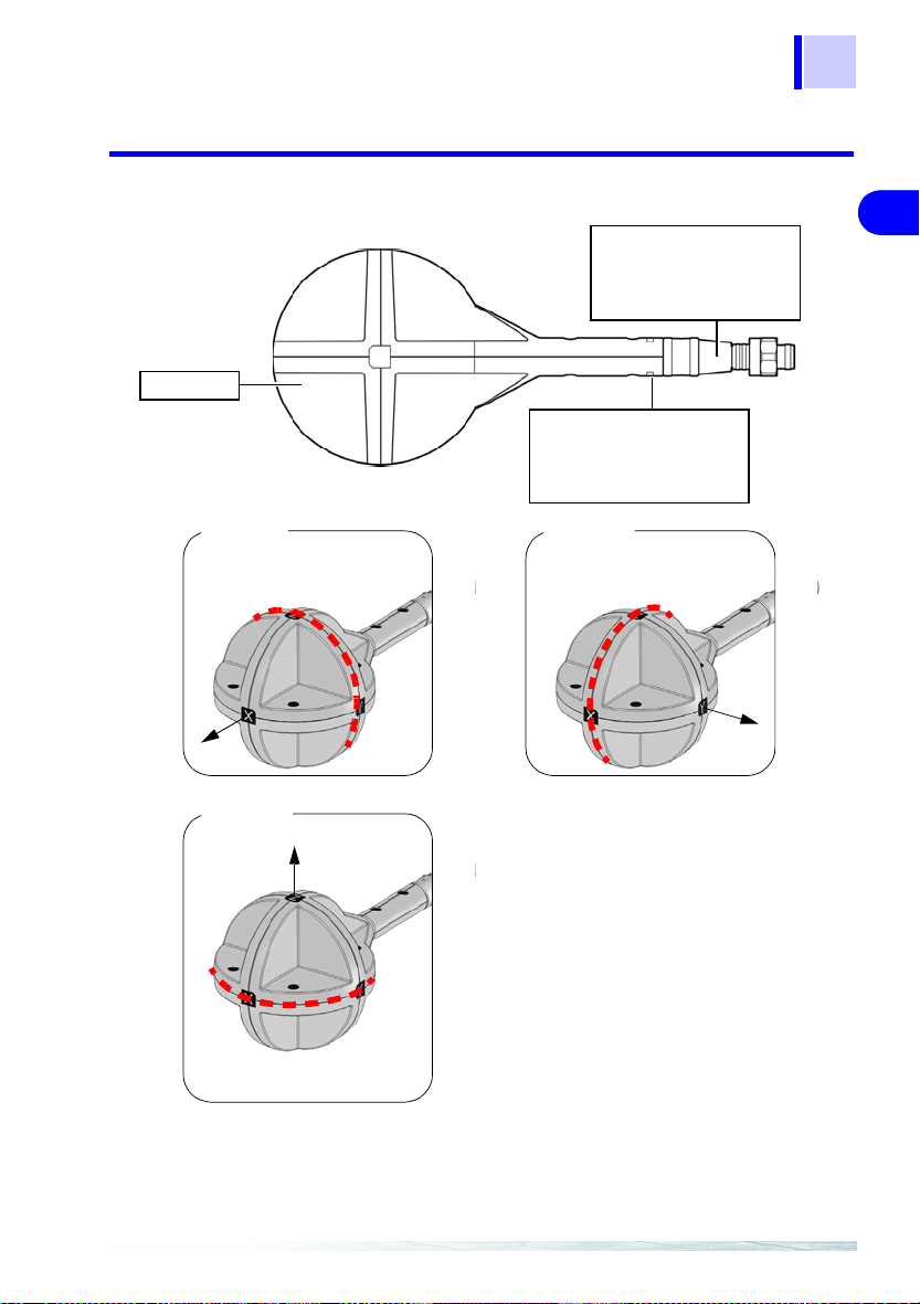
1.4 Names and Functions of Parts
1.4.2 3471 Magnetic Field Sensor
z
yx
Sensor
Output conn ector
Connects to the 3470 sensor
connector.
2.2 (P. 32)
Matching number
Use the tester with a sensor
that has an identical matching
number (up to the hyphen).
21
1
2
3
4
x-axis coil
The dotted line indicates the
x-axis coil.
x-axis
z-axis coil
z-axis
The dotted line indicates the
z-axis coil.
y-axis coil
The dotted line indicates the
y-axis coil.
y-axis
5
6
7
8
9
10
11
12
13
Page 28

22
1.4 Names and Functions of Parts
1.4.3 3472 Magnetic Field Sensor
Output connector
Connects to the 3470 sensor connector.
2.2 (P. 32)
The line indicates the
x-axis coil.
z
yx
Matching number
Sensor
y-axis coil z-axis coil
The line indicates the
z-axis coil.
Use the tester with a sensor
that has an identical matching
number (up to the hyphen).
y-axis
x-axis
x-axis coil
z-axis
The line indicates the z-axis coil.
Page 29
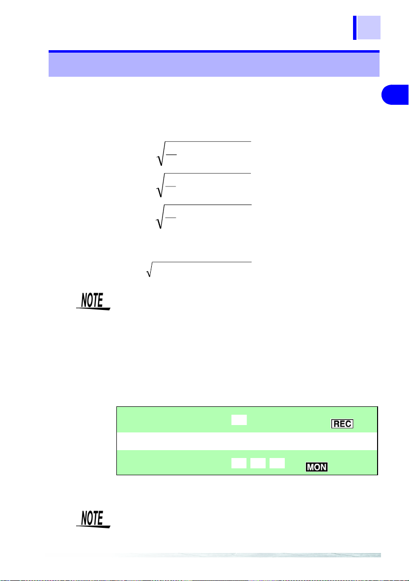
1.5 Definition of Measurement Items
)(tx)(ty)(tz)(ˆtx)(ˆty)(ˆt
)
ˆ
tR
)
ˆ
tR
)(ˆtx)(ˆty)(ˆtz)(tx)(ty)(t
1.5 Definition of Measurement Items
Instantaneous values obt ained from the x- axis, y-axis and z-axis sensors
at time t are referred to as, respectively,
RMS values are respectively , and . The RMS values used
by this tester represent the values shown below. (T when the slow function is turned off is about 0.12 s and about 1 s when the function is on.)
t
ˆ
tx
)(
ˆ
ty
)(
ˆ
tz
)(
1
=
=
=
∫
−
Tt
T
t
1
∫
−
Tt
T
t
1
∫
−
Tt
T
2
dttx
)}({
2
dtty
)}({
2
dttz
)}({
, and while the
z
23
1
2
3
4
A resultant RMS value represents the following.
ˆ
• The IEC62233 and EN50366 standards state that "Transient magnetic fields with a duration of less than 200 ms, e.g. during switching
events, are disregarded. If a switching action o ccurs d uring t he mea
surements, the measurement has to be repeated."
Transient responses may not be correctly measured when slow
function is off. Make a new measurement if this happens.
• T o make a 1 s measurement that includes transient responses, measure using the slow function while being mindful of the timing that
transient responses occur.
4.4.4 "Setting the Slow Function" (P.68)
The above can be summarized as shown below.
Resultant RMS value :
RMS value (per axis):
Instantaneous value (per axis):
These are the same both in magnetic flux density mode and exposure
level mode.
Resultant RMS and RMS values (for each axis) can be viewed on a
PC using the application software (on CD) supplied with the tester .
5.1 "Overview" (P.73)
ˆ
{}{}{}
)(
)(
(
ˆ
)(
222
ˆ
)(
tztytxtR ++=
(
, , :
, , :
-
LCD reading, RMS
:
output ( )
LCD reading
z
Waveform output
(
)
5
6
7
8
9
10
11
12
13
Page 30

24
.
.
1.6 Screen Configuration and Key Operation Work Flow
1.6 Screen Configuration and Key Operation
Work Flo w
3.3 (P . 38)
Magnetic flux density mode
(10 Hz to 400 kHz)
3.3 (P . 38)
Press .
Magnetic flux density mode
(10 Hz to 2 kHz)
Measurement mode
Tindicates selected mode.
Magnetic flux density
mode
3.5 (P. 48)
Exposur level
(Occup.) mode
Exposure
level mode
Press
3.3 (P . 38)
Press .
Magnetic flux density mode
(2 kHz to 400 kHz)
Press .
3.4 (P. 41)
Exposure level
(General Public) mode
Press
Page 31

1.6 Screen Configuration and Key Operation Work Flow
Screens for verifying and setup
25
Screen name Screen access method Screen displayed
Check Battery status
Check Saved Data
Set Auto Power Off When the power is off, hold
Press to view battery
status.
3.1 (P. 35), 4.1 (P. 59)
Press in each measurement mode.
3.7.1 (P. 52)
down and and
press or to turn
on
[APS].
4.4.1 (P. 62)
1
2
3
4
5
6
7
8
Set Audible Key
Feedback
When the power is off, hold
down and . And
press or to turn
BEEP].
on [
4.4.2 (P. 64)
9
10
11
12
13
Page 32

26
1.6 Screen Configuration and Key Operation Work Flow
Screen name Screen access method Screen displayed
Change Unit Indication When the pow e r is of f, ho l d
down and . And
press or to turn
on [
Unit].
4.4.3 (P.66)
Set Slow Function When th e p o wer i s off , h o l d
down and . And
press or to turn
SLou].
on [
4.4.4 (P. 68)
Enable/disable MEM.
MODE Key in MAX.
HOLD or Output Mode
QuickSet
The slow function is on in
Exposure l evel (General
Public) mode when powering on.
When the power is off, hold
down and . And
press or to turn
on [
MEM.M].
4.4.5 (P. 70)
When the power is off, hold
down and .
(P. 42)
Page 33

1.7 Measurement Work Flow
1.7 Measurement Work Flow
This section describes measurement work flow.
Supplying power
1.
2.1.1 "Connecting the
AC Adapter" (P.29)
2.1.2 "Inserting and
Replacing Batteries"
(P.30)
Connect a mag-
2.
netic field sensor.
2.2 "Connecting a
Magnetic Field Sensor" (P.32)
27
1
2
3
4
5
6
7
Turn on the power.
3.
2.3 "Turning the Power
On and Off" (P.33)
8
9
10
11
12
13
Page 34

28
5.
1.7 Measurement Work Flow
4. Pre-measurement check
3.2 "Pre-measurement Check" (P.37)
Measuring magnetic fields
3.3 "Measuring Mag-
netic Flux Density"
(P.38)
Transfer the mea-
6.
surement data to a
PC and use the
application soft
ware to analyze
the data.
5.3 "Graphic Repre-
sentation of Measurement Values" (P.85)
5.4 "Transferring
Recorded Data to a
PC" (P.88)
-
Page 35

2.1 Supplying Power
9
Measurement Preparations 2
2.1 Supplying Power
2.1.1 Connecting the AC Adapter
Use only the specified Model 9445-02 AC Adapter (SA110-09S-I,
SINO-AMERICAN) AC adapter input voltage range is 100 to 240
VAC (with ±10% stability) at 50/60 Hz. To avoid electrical hazards
and damage to the instrument, do not apply voltage outside of
this range.
• Make sure the power is turned off before connecting or disconnecting the AC adapter.
• Use the AC adapter for long-term measurements.
Connect the AC adapter according to the steps below
1. Connect the 9445-02 AC Adapter to the AC adapter terminal.
29
2
2
3
4
5
6
7
8
445-02 AC Adapter
9
10
2. Connect th e AC adapter plug to an AC wall outle t .
This completes AC adapter connection.
11
12
13
Page 36

30
2.1 Supplying Power
2.1.2 Inserting and Replacing Batteries
• Do not mix old and new batteries, or different types of batteries.
Also, be careful to observe battery polarity during installation.
Otherwise, poor performance or damage from battery leakage
could result.
• To avoid the possibility of explosion, do not short circuit, disassemble or incinerate batteries.
• Handle and dispose of batteries in accordance with local regulations.
• The indicator appears when battery voltage becomes low.
Replace the batteries as soon as possible.
• Use battery power to run the tester for brief measurement sessions
in locations without AC power.
• Disconnecting and connecting the AC adapter during measurements when the tester is both battery and AC powered may cause
the measurement values to fluctuate greatly.
Use the following steps to insert (replace) the batteries.
Required batteries: LR6 alkaline battery
1. Remove th e battery compartment li d.
Remove
Battery compartment lid
2. When replacing batteries, first remove the old batteries.
Page 37

31
2.1 Supplying Power
3. Insert the batteries taking care to match the pola rit y correctly.
2
2
3
4. Attach the battery compartment lid.
Attach
Battery compartment lid
This completes the battery insertion (replacement) procedure.
4
5
6
7
8
9
10
11
12
13
Page 38

32
2.2 Connecting a Magnetic Field Sensor
2.2 Connecting a Magnetic Field Sensor
Use the sensor within its specifie d range. In a high frequency and strong magnetic field, the sens or w ill output
a high voltage that may cause electric shock or sensor
damage when someone touches an unconnected output
terminal.
Observe the rating and the derating curve of the sensor
during operation.
Connect the magnetic field sensor (3471 or 3472) accor ding to the st eps
below.
The 3471, intended for normal application, has a cross-sectional
area of 100 cm
The 3472 sensor has a cross-sectional area of 3 cm2 and is
designed for measuring detailed magnetic field distribution.
2
.
Locate the Z-axis of the magn etic field sen sor facing forwa rd,
insert the output connector of the sensor in the 3470 sensor
connector and screw the nut of the se nsor in to firmly at tach
the sensor.
The sensor automatically recognize s the connected m agnetic
field sensor.
Output connector
Sensor connector
To avoid damaging the output cable, grasp the connector, not the
cable, when unplugging the cable.
This completes connection of 3471 and 3472 magnetic field sensors.
Page 39

2.3 Turning the Power On and Off
2.3 Turning the Power On and Off
Turn the power on (off) according to the steps below.
T urning on the power
Press .
33
2
2
3
4
5
T urning the power off
Hold down for 2 seconds or m ore.
2 seconds
or more
6
7
8
9
10
11
12
13
Page 40

34
2.3 Turning the Power On and Off
Page 41

3.1 Measurement Preparations
Measurement Procedure 3
3.1 Measurement Preparations
35
Before the start of measurements, make the following preparations in
the stated order.
1. Press to turn on the power.
2. Make sure th at all s egm ents on the LCD display light.
After this it will display the model name (3470) and battery status.
2
3
3
4
5
6
7
8
9
10
11
12
13
Page 42

36
3.1 Measurement Preparations
Function for checking low battery voltage
When battery voltage goes low and lights, the power is
forcibly turned off. At this time, [BAtt] [Lo] also appear.
3. The magnetic flux den si ty m ode screen appears.
This ends measurement preparations.
• When a setup has been saved (for details refer to 4.2 "Function for
Saving Settings (Saving Set Modes and Measurement Ranges)"
(P.60)), the set measurement mode screen appears.
• To initialize the tester (to return it to its factory defaults), turn off the
power and then hold down
4.3 "Initializing Function (Returning Settings to Their Factory Defaults)" (P.61)
and press .
Page 43

3.2 Pre-measurement Ch eck
This instrument has been calibrated to operate with the optional sensors and should be used only with these sensors. Thus if multiple
instruments are used, make sure that each instrument is combined
with the correct sensor.
Check the following before using the tester.
Inspection flow chart
1.
Check whether the magnetic field sensor, the
tester case, the 9759 Output Cable and the USB
cable are damaged.
Damaged
3.2 Pre-measurement Check
Do not use the tester if any of
the cables are da maged and
the cable metal core is visible.
37
2
3
3
4
5
No
damage
2.
Check if the battery is
depleted after powering
up. Check battery status.
4.1 "Checking Remaining Battery
Power" (P.59)
Sufficient
battery
power
Start
measurements
Magnetic field sensor and tester case must be repaired. Contact your
dealer (agent) or local sales office.
Replace the 9759 Output Cable and USB cable with new cables.
Insufficient
battery
power
lights when battery power is low.
The tester is not able to make accurate measurements when battery
power is low. Replace the battery.
2.1.2 "Inserting and Replac-
ing Batteries" (P.30)
6
7
8
9
10
11
12
13
Page 44

38
3.3 Measuring Magnetic Flux Density
3.3 Measuring Magnetic Flux Density
Measure magnetic flux density according to the steps below.
5
21
1. Press to open the magne ti c flux density mode screen.
: wide range measurements
: power frequency range measurements
: extended power frequency range measurements
Page 45

3.3 Measuring Magnetic Flux Density
2. Press to select measure m ent range.
Range number
Ranges are switched in the order
shown belo w.
AUTO r0 r1 r2 r3
39
2
3
3
Range type Range number Range
Auto-range
Manual range r0 2 μT/20 mG/1.6 A/m
Magnetic flux density switching is performed by converting from T
(Tesla).
For this reason, for example, 1.592 A/m is the maximum indicated value
in the 1.6 A/m range.
• The ranges for the x, y and z axes are interlocked with maximum
range and are automatically switched.
Range of guaranteed accuracy
At resultant value R, a count of less than 100 is outside guaranteed
accuracy.
Use an appropriate range.
Guaranteed accuracy range for resultant value R
Magnetic flux density (10 Hz - 400 kHz, 10 Hz - 2 kHz, 2 kHz - 400 kHz)
Fixed range
※0.1 uT
※The magnetic flux densi t y for 3472 (10 Hz - 400 kHz, 10 Hz - 2 kHz) is 0.4 uT.
1 uT 20 uT
2 uT
3.464 uT
10 uT
appears on the
display
r1 20 μT/200 mG/16 A/m
r2 200 μT/2 G/160 A/m
r3 2 mT/20 G/1600 A/m
0.1 mT 2.0 mT
200 uT
34.64 uT
Automatically selects
appropriate range dur
ing measurements.
346.4 uT
3.464 mT
-
r3
r2
r1
r0
4
5
6
7
8
9
10
11
12
13
Page 46

40
3.3 Measuring Magnetic Flux Density
3. Place the mag netic field se nsor near the DUT.
• For accurate measurements, the tester should be located further
away from the DUT than the sensor.
• Although few magnetic materials are used in the magnetic field
tester, the battery is a magnetic material and may affect measure
ments if located close to the DUT. In this situation, it may be a good
idea to use an extension cable to increase the distance between the
sensor and the tester or to remove the battery and use the AC
adapter.
-
4. Read the indicated value.
5. Press to save the mea s urement data.
This ends magnetic flux density measurements.
Page 47

3.4 Measuring Exposure Level (General Public)
3.4 Measuring Exposure Level
(General Public)
Use this mode to make measurements that conform to EN50366 and
IEC62233.
3.4.1 Preparing for Exposure Measurements
41
2
Use the flow chart below to determine whether to use the slow function
setting.
Slow function setting assessment flow chart
Use this test to determine whether the test of a household appliance
should conform to IEC62233 or EN50366.
START
Waveform of mag-
netic field to be mea-
sured is known
Yes
Yes No
Turn off the slow
function
*: Since turning the slow function on or off will not change the value of a magnetic field
that periodically fluctuates by 10 Hz or more, turn the slow function off to speed up
measurements.
This is beca use movi ng t he sen sor caus es th e det ec tion of AC curr ent gene rate d by
a DC magnetic field such as the terrestrial magnetic field and other AC magnetic
fields. Twice the integral time is then required including processing time for the mea
surement value to stabilize.
A magnetic field that
periodically fluctu-
ates by 10 Hz or
more?*
No
Turn on the slow
function
-
3
3
4
5
6
7
8
9
10
11
12
13
Page 48

42
3.4 Measuri ng Exposure Level (General Public)
The result of the flo w chart assessment is "Turn on the
slow function."
Use the steps below to open the "QuickSet" screen. (An exposure level
(General Public) measurement can be started after turning on the slow
function.)
When the power is of f, hold dow n and press .
The "QuickSet" screen opens
After this follow the procedures 2. (P.46) described in 3.4.3
"Measurement Procedure" to perform an exposure level (General Public) measurement.
The result of the flow chart assessment is "Turn off the
slow function."
The result of the flow chart assessment is "Turn off the slow function."
Turn off the slow function as described in 4.4.4 "Setting the Slow Function" (P.68). (The default setting is "Off.")
Page 49

43
g
3.4 Measuring Exposure Level (General Public)
The table below shows the measurement and internal processing times
with the slow function on and when it is off.
Slow function on
1 s 1 s 1 s 1 s 1 s 1 s 1 s 1 s
Measure-
Internal
ment
processing
Measurement
Internal
processing
Measurement
Internal
processing
Measurement
Internal
processin
2
Slow function off
0.12 s 0.13 s 0.12 s 0.13 s 0.12 s 0.13 s 0.12 s 0.13 s
Measure-
Internal
processing
ment
3.4.2 Exposure Level
• Values obtained in an exposure measurement are not measures of
the risk a specific magnetic field poses.
• In Exposure Level mode, first order filters are used to approximate
magnetic density flux levels in the ICNIRP guideline. Thus corner
frequencies cause a difference of at most 3 dB, but this corresponds
to the "smoothed edges" referred to in IEC62233 or EN50366.
• A discussion of acute health effects of exposure must acco unt for coupling factors such as the human body and magnetic fields, threshold
values under basic restrictions and safety factors (reduction factor) for
general public and occupational exposure.
Reference:
In IEC62233, the coupling factor at 10 cm as described in ICNIRP is
"0.14" for small and "0.16" for large ones while the safety factor
(reduction factor) (the reduction factor for public exposure is "50" (1/
50 of the threshold value) for threshold values for occupational expo
sure is "10" (1/10 of the threshold value).
For details, see "Appendix" (P . 111).
Measurement
Internal
processing
Measurement
1 s
Internal
processing
Measurement
Internal
processing
3
3
4
5
6
7
8
9
10
11
-
12
13
Page 50

44
3.4 Measuri ng Exposure Level (General Public)
• In measuring non-uniform magnetic fields (see figure below) where
the sensor may come into contact with a source, it is recommended
that measurements be conducted at a distance from the three coils
and at an angle (indicated by
ropy of each axis.
The IEC62233 and EN50366 standards do not mention sensor angle.
Reference
Uniform magnetic field
in the figure below) to maintain isot-
Non-uniform magnetic
field
Magnetic field s ensor
Magnetic
field
field
Magnetic
Magnetic field
Magnetic fiel d
Source
Measure at an angle away from the three coils
The locatio ns indicat ed by (8 points on t he spheri cal sens or surfac e) should be
maintained in a vertical attitude relative to the DUT.
Page 51

3.4 Measuring Exposure Level (General Public)
3.4.3 Measurement Procedure
Measure exposure level (General Public) according to the steps below
45
5
21
1. Press to open the exposure level (General Public)
mode screen.
2
3
3
4
5
6
7
8
9
10
11
12
13
Page 52

46
accuracy range
3.4 Measuri ng Exposure Level (General Public)
2. Press to select meas urement range.
Range number
Ranges are switched in the order
shown below .
AUTO r0 r1 r2
Range type Range number Range
Auto-range
Manual range r0 20%
appears on the
display
r1 200%
r2 2000%
Automatically selects
appropriate range dur-
ing measurements.
Range of guaranteed accuracy
At resultant value R, a count of less than 100 is outside guaranteed
accuracy.
As a result, when R is 99% or less in range r2, it is not within guaranteed accuracy .
Use an appropriate range.
Guaranteed accuracy range for resultant value R
Exposure level (General Public, Occup.) Fixed range
10% 200%
1% 20%
Guaranteed
100% 2000%
346.4%
34.64%
Conditional guaranteed accuracy range (when none of x, y, z are O.L.)
3464%
r2
r1
r0
Page 53

3.4 Measuring Exposure Level (General Public)
DUT
m
3. Place the magnetic field sensor near the D U T.
47
2
3
3
• For accurate measurements, the tester should be located further
away from the DUT than the sensor.
• Although few magnetic materials are used in the magnetic field
tester, the battery is a magnetic material and may affect measure
ments if located close to the DUT. In this situation, it may be a good
idea to use an extension cable to increase the distance between the
sensor and the tester or to remove the battery and use the AC
adapter.
• For details on measuring distance from DUT, sensor location and
operating conditions, refer to the following documents.
(IEC62233 or EN50366)
• The center of the 3471 sensor is located at right
angles to the x, y and z axes. Since the distance from the center to the spherical surface is
61 mm and the distance to the DUT is a mm,
locate the tester so that the distance from the
surface of the DUT to the center of the sensor
is (a + 61 mm). Calculate the measurement dis
tance from the surface of protrusions on the DUT.
-
4. Read the indicated value.
5. Press to save the measurement data.
4
-
5
6
a mm
61 m
7
8
9
10
11
This ends exposure (General Public) measurements.
12
13
Page 54

48
3.5 Measuri ng Exposure Level (Occup.)
3.5 Measuring Exposure Level (Occup.)
Measuring Exposure Level (Occup.)
5
21
1. Press to open the exposure level (Occup.) mode screen.
Page 55

3.5 Measuring Exposure Level (Occup.)
accuracy range
2. Press to select measure m ent range.
Range number
Ranges are switched in the order
shown below.
AUTO r0 r1 r2
Range type Range number Range type
Auto-range
Manual range r0 20%
appears on the
display
r1 200%
r2 2000%
Automatically selects
appropriate range dur-
ing measurements.
49
2
3
3
4
5
6
Range of guaranteed accuracy
At resultant value R, a count of less than 100 is outside guaranteed
accuracy.
As a result, when R is 99% or less in range r2, it is not within guaranteed accuracy.
Use an appropriate range.
Guaranteed accuracy range for resultant value R
Exposure level (General Public, Occup.) Fixed range
10% 200%
1% 20%
Guaranteed
100% 2000%
346.4%
34.64%
Conditional guaranteed accuracy range (when none of x, y, z are O.L.)
3464%
r2
r1
r0
7
8
9
10
11
12
13
Page 56

50
3.5 Measuri ng Exposure Level (Occup.)
3. Place the mag netic field se nsor near the DUT.
• For accurate measurements, the tester should be located further
away from the DUT than the sensor.
• Although few magnetic materials are used in the magnetic field
tester, the battery is a magnetic material and may affect measure
ments if located close to the DUT. In this situation, it may be a good
idea to use an extension cable to increase the distance between the
sensor and the tester or to remove the battery and use the AC
adapter.
-
4. Read the indicated value.
5. Press to save the m easurement data.
This ends exposure level (Occup.) measurements.
Page 57

51
3.6 Holding Maximum Value of the Resultant RMS Values
3.6 Holding Maximum Value of the Resultant
RMS Values
This function holds the maximum value of the resultant RMS value R
and the values of each axis.
1, 2
2
3
3
1. Press to hold the maximum value of the resultant RMS
value R and the icon lights.
The update of the maximum value will occur as a bigger resultant
RMS value is observed. Therefore it is possible that the value of x, y,
or z axis may decrease.
2. Press again to turn off an d clear held maximum
data value.
The screen returns t o the st ate i t had befor e was pres sed.
4
5
6
7
8
9
10
11
12
13
Page 58

52
3.7 Checking and Deleting Saved Data
3.7 Checking and Deleting Saved Data
3.7.1 Checking Saved Data
Use the following steps to check saved measurement data.
You can save up to 99 data.
3
2
1, 2
1. Press to open the scree n w it h th e s av ed data.
Page 59

53
3.7 Checking and Deleting Saved Data
2. Press (S) or (T) to select the memory number of
measurement data you wish to check.
Memory number
3. Press to return to the meas urement mode screen.
This completes saving measurement data
blinks when measurement data is saved with the slow function
ON.
2
3
3
4
5
6
7
8
9
10
11
12
13
Page 60

54
3.7 Checking and Deleting Saved Data
3.7.2 Deleting Saved Data
Use the following steps to delete saved measurement data.
3
2
1, 2
1. Press to open the scree n w it h th e s av ed data.
Page 61

3.7 Checking and Deleting Saved Data
2. Press and hold for 2 seconds or more.
This deletes the measur ement data with the highest memory
number.
Data can deleted only when moved to the highest memory
number.
Highest memory
number
[dAtA] [cLr] appea r when data is deleted.
55
2
3
3
4
5
6
The data for the next highest m em ory number appears.
7
8
9
10
11
12
13
Page 62

56
3.7 Checking and Deleting Saved Data
3. Press to return to th e m eas urement mode screen.
This completes deleting measurement data.
Page 63

3.7.3 Deleting All Saved Data
Use the following steps to delete all saved measurement data.
When the power is off, hold down and press .
This deletes all saved data.
[dAtA] [cLr] appea r when data is deleted.
3.7 Checking and Deleting Saved Data
57
2
3
3
4
5
6
Then the model name (3470), battery status and the measurement mode screen appear.
This completes deleting all saved data.
7
8
9
10
11
12
13
Page 64

58
3.7 Checking and Deleting Saved Data
Page 65

4.1 Checking Remaining Battery Power
Advanced Functions 4
4.1 Checking Remaining Battery Power
59
Use the procedure below to check remaining battery power.
Press .
The measurement mode screen appears after showing battery status.
2
3
4
4
5
6
7
8
9
The screen indicates 100% battery power regardless of battery status
when the 9445-02 AC Adapter is connected. (A reading of 100% may
not appear when the USB cable is connected.)
10
11
12
13
Page 66

60
4.2 Function for Saving Settings (Saving Set Modes and Measurement Ranges)
4.2 Function for Saving Settings (Saving Set
Modes and Measurement Ranges)
A frequently used mode can be saved for immediate access.
The saved mode appears as soon as the tester is powered up.
Follow the steps given below.
Select the mode or range y ou wish to access upon po wering
up and hold down
[SAvE] [End] appear and the tester returns to the screen prior
to saving settings.
for 2 seconds or more.
Approx. 2 s
Page 67

61
4.3 Initializing Function (Returning Settings to Their Factory Defaults)
4.3 Initializing Function (Returning Settings to
Their Factory Defaults)
This function initializes all settings returning them to their factory default s
and deletes all saved data. Follow the steps given below.
When the power is off , h old dow n to press .
[All clr] appears.
After this it displays the model name (3470) and battery status, and
is restarted using the factory default settings.
The factory default settings are listed in the table below.
Item Settings
Mode Magnetic flux density
Range AUTO
Output None
Auto power off Enabled
Buzzer Enabled
Axis XYZ
Slow function OFF
Unit T
(10 Hz to 400 kHz)
2
3
4
4
5
6
7
8
9
10
11
12
13
Page 68

62
4.4 Other Functions
4.4 Other Functions
The following sections describe other functions that a user should know .
4.4.1 Setting Auto Power Off (Saving Battery Power)
• This funct ion saves bat tery power w hen the user forgets to tur n off the
power.
• The tester is automatically turned off 10 m inutes a fter the last key press.
• lights when th e au to p o we r o f f fu n ctio n is on. B efo re tu rni ng o ff th e
tester, the icon flashes and sounds a buzzer tone (for about 30 s).
Pressing any key during this interval p ostpone s shutdo wn by 10 minute s.
Follow the steps given below.
1, 4
3
2
1, 2
1. When the power is off, hold down and pr ess .
Page 69

4.4 Other Functions
2. Press (S) or (T) to turn on .
63
2
3
3. Press and select [y] or [n].
[y] : set auto power off.
[n] : cancel auto power off.
y
n
4. Press to save the se tting.
[SAvE] [End] appear and the pow er is tu rned off.
4
4
5
6
7
8
9
10
11
12
13
Page 70

64
4.4 Other Functions
4.4.2 Setting Audible Key Feedback
This function causes the keys to generate a beep when pressed.
Follow the steps given below.
1, 4
3
2
1, 2
1. When the power is off, hold down and pr ess .
2. Press (S) or (T) to turn on [bEEP].
Page 71

3. Press and select [y] or [n].
[y] : audible key feedback is on.
[n] : audible key feedback is off.
y
65
4.4 Other Functions
2
n
3
4. Press to save the se tting.
[SAvE] [End] appear and the pow er is tu rned off.
4
4
5
6
7
8
9
10
11
12
13
Page 72

66
4.4 Other Functions
4.4.3 Changing Unit Indication
Use this function to change the unit indication. (The default unit is T.)
Follow the steps given below.
1, 4
3
2
1, 2
1. When the power is off, hold down and pr ess .
2. Press (S) or (T) to turn on [Unit].
Page 73

4.4 Other Functions
3. Press and select [T], [G], or [A/m].
67
4. Press to save the se tting.
[SAvE] [End] appear and the pow er is tu rned off.
T, G, or A/m
2
3
4
4
5
6
7
8
9
10
11
12
13
Page 74

68
4.4 Other Functions
4.4.4 Setting the Slow Function
This function performs 1 s sampling and then displays the measurement
value.
Follow the steps given below.
1, 4
3
2
1, 2
1. When the power is off, hold down and pr ess .
2. Press (S) or (T) to turn on [SLou].
Page 75

3. Press and select [y] or [n].
[y] : sets the slow function.
[n] : cancels the slow function.
y
69
4.4 Other Functions
2
n
3
4. Press to save the se tting.
[SAvE] [End] appear and the pow er is tu rned off.
blinks while measuring with the slow function on.
4
4
5
6
7
8
9
10
11
12
13
Page 76

70
4.4 Other Functions
4.4.5 Turning on the MEM. MODE key in MAX. HOLD or output mode
Use this function to turn on or of f the during MAX. HOLD or during
output.
Checking saved data during output results in output off
Follow the steps given below.
1, 4
3
2
1, 2
1. When the power is off, hold down and press .
2. Press (S) or (T) to turn on [MEM.M].
Page 77

3. Press and select [y] or [n].
71
4.4 Other Functions
[y] :
[n] :
enables in MAX. HOLD mode and output
modes.
disables in MAX. HOLD mode and output
modes.
y
n
4. Press to save the se tting.
[SAvE] [End] appear and the pow er is tu rned off.
2
3
4
4
5
6
7
8
9
10
11
12
13
Page 78

72
4.4 Other Functions
Page 79

5.1 Overview
Using Application Software 5
5.1 Overview
73
The application software supplied with the 3470 provides the following
functions.
Functions Functions in detail See:
Graphic representation
of measurement values
Transfer recorded data
to a PC
Configure the 3470
from a PC
View application software version
The supplied PC driver and the ap plic ation software must be installed o n
a PC to enable downloading data from the 3470 tester.
5.2 "Installing" (P.74)
Operating environment
Supported
operating
system
Hard
disk capacity
Interface
USB hubs with a power consumption exceeding 100 mA must be selfpower hubs.
CD configuration
Folder
File
Select "small font" for the operating system since "large font" may
cause irregularities in screen indications.
Japanese
English
HiUsbSgl.inf File for installing driver
HiUsbSgl.sys 3470 USB device driver
accuracy.dat Accuracy file
Analyzing measurement data on a PC5.3 (P. 85)
5.4 (P. 88)
Configuring the 3470 from a PC 5.5 (P. 91)
Checking version of application software
• Windows 98, Me, 2000, XP
• The hardware environment comprising CPU,
memory, display, etc. must conform to operating
system recommendations.
• 10 MB or more free disk space
• USB Ver. 1.1 or greater
• One 3470 unit can be connected at any one time
Folder containing the application configuration file
5.6 (P. 93)
2
3
4
5
5
6
7
8
9
10
11
12
13
Page 80

74
1
2
5.2 Installing
5.2 Installing
The major installation procedures are listed below.
Install the driver.
5.2.1 "Installing the Driver" (P.74)
Install the PC software.
5.2.2 "Installing software" (P.82)
5.2.1 Installing the Driver
The driver installation procedures are described below.
Do not connect and disconnect the USB cable during operations. Disconnecting the USB cable will prevent normal completion of the installation procedure.
• Only one 3470 tester can be connected to one PC.
• You may be informed that a new device has been detected also
when a 3470 tester with a different serial number is connected.
Install the device driver according to the on-screen instructions.
1. Turn on the tester.
2. Use the supplied USB cable to connect the 3470 tester wit h
the PC where the driver is to be ins talled .
(PC operations)
The 3470 tester is recognized as "HIOKI Single USB Products."
After the "Found New Hardware" screen, the "Fou nd New Hardware Wiz-
ard" appears.
The procedures for "Found New Hardware Wizard" depends on the PC
operating system.
Page 81

75
5.2 Installing
Insert the CD according to the instructions that appear to install the
driver.
Installation procedures for each operating system are provided below.
"WindowsXP" (P.75)
"Windows2000" (P.76)
"WindowsMe" (P.78)
"Windows98" (P.79)
WindowsXP
1. Insert the supplied C D in the CD-ROM drive.
2. Select "Install the software automatically" and click [Next].
3. Click [Continue].
The "Found New Hardware Wizard" appears.
2
3
4
5
5
6
7
8
9
Clicking this button starts file copying. When the operating system
detects the software, a message noti fies the use r that this sof tware i s not
recognized by Microsoft. Select [
Continue Anyway].
10
11
12
13
Page 82

76
5.2 Installing
4. Click [Finish].
5. Remove the CD from the CD-ROM drive when the "Found
Windows2000
1. Click [Next] when the "Found New Hardware Wizard" appears.
New Hardware Wizard" screen closes.
To install further software, go to Section 5.2.2 "Installing software" (P.82)
2. Insert the supplied CD in the CD-ROM drive.
Page 83

77
5.2 Installing
3. Select "Search for a suitable driver for my device" and click
[
Next].
2
3
4
4. Select "CD-ROM drives" (deselect other alternatives) and click
Next].
[
5
5
6
5. Click [Next].
7
8
9
10
11
12
13
Page 84

78
5.2 Installing
6. Click [Finish].
7. Remove the CD from the CD-ROM drive when the "Found
WindowsMe
New Hardware Wizard" screen closes.
To install further software, go to Section 5.2.2 "Installing software" (P.82)
1. Insert the supplied CD in the CD-ROM drive.
The "Add New Hardware Wizard" appears.
2. Select "Automatic search for a better driver" and click [Next].
Page 85

3. Click [Finish].
79
5.2 Installing
2
3
4. Remove the CD from the CD-ROM drive when the "Add New
Windows98
1. Click [Next] when the "Add New Hardware Wizard " appears.
Hardware Wizard" screen closes.
To install further software, go to Section 5.2.2 "Installing software" (P.82)
4
5
5
6
7
8
9
10
11
12
13
Page 86

80
5.2 Installing
2. Select "Search for the b est driver for your device" and click
[
Next].
3. Insert the supplied CD in the CD-ROM drive.
4. Select "CD-ROM drive" (deselect other alternatives) and click
[
Next].
5. Click [Next].
Clicking this button starts file copying.
Page 87

5.2 Installing
6. Click [Finish] in the nex t sc reen that appears.
81
2
3
7. Remove the CD from the CD-ROM drive when the "Add New
Hardware Wizard" screen closes.
To install further software, go to Section 5.2.2 "Installing software" (P.82)
4
5
5
6
7
8
9
10
11
12
13
Page 88

82
5.2 Installing
5.2.2 Installing software
The software installation procedures are described below.
1. Close all currently active applic at ions on the PC.
2. Insert the CD (PC application software) supplied with the
instrument into the CD-ROM drive.
3. Open the folder [Eng lish] included on the CD, then execute
Setup.exe.
This will activate the installer and open the "DATA VIEWER for 3470
" window.
(EN)
4. Click [Next].
4.
Page 89

83
5.2 Installing
5. Click [Change], then specify the installing destination folder.
Click [Next].
Click this button when specify
the installing destination.
6. Click [Install].
2
3
4
5
5
6
7. When installati on ends, click [Finish] in the checking window.
Installation is now complete.
7
8
9
10
11
12
13
Page 90

84
5.2 Installing
Uninstallation
1. Select [Setup] - [Control Panel] from the [Start] menu, then
2. Select "
3. Uninstall the program by following the procedure appearing on
Select [Program] - [HIOKI] - [DATA VIEWER for 3470] - [DATA VIEWER for
3470 (EN)
click [
[
Change/Remove].
the screen.
] from the [Start] menu of Windows to activate the application.
Add/Remove Programs].
DATA VIEWER for 3470 (EN)
," then click [
Remove
] or
Page 91

5.3 Graphic Re presentation of Measurement Values
5.3 Graphic Representation of Measurement Values
Measurement values obtained using the 3470 tester can be imported to
a PC for graphic representation.
85
1. Turn on the 3470 and select [HIOKI]-[DATA VIEW ER for 3470]-
[
DA TA VIEWER for 3470 (EN)] from the Start button on the PC.
2
3
2. Connect the tester to a PC using the supplied USB cable.
(Push the cable plugs all the way in.)
4
5
5
USB cable
6
on the 3470 lights an d all key operations o ther than
the are disabled.
• Only one 3470 tester can be connected to a PC at one time.
• The effective value logger can obtain up to 32000 data.
7
8
9
10
11
12
13
Page 92

3.
7.
2
86
5.3 Graphic Representation of Measurement Values
3. Click the "Effective Value Logger" tab in the "HIOKI DATA
VIEWER for 3470" window to open the "Effective Value
Logger" screen.
6.
Menu item Description
Fixed Interval Samples at fixed intervals to obtain 20 points per
Average Calculates the average of sampling data obtained in
Maximum Indicates data when resultant RMS value R is at its
Drop-down list box for
sampling interval
R/ x/ y/ z Turn R, x, y and z data indication On and Off.
File Read Represents saved data in graphic form and saves it
CSV Save Saves graph data.
Start Starts measurements.
Stop Stops measurements.
Print Prints graphs
division.
drawing 1 point.
(Equation)
t
ˆ
x
ˆ
y
ˆ
z
ˆ
maximum among the sampling data obtained in
drawing 1 point.
Selects sampling interval. When the slow function is
set to ON, 1 s/div and 5 s/div are not available.
2
dtx
∫
Tt
−
T
t
2
dty
∫
Tt
−
T
t
2
dtz
∫
Tt
−
T
22
ˆˆ
ˆ
zyxR ++=
N
11
2
==
==
==
ˆ
x
∑
n
N
n
=
1
N
11
2
ˆ
y
∑
n
N
n
=
1
N
11
2
ˆ
z
∑
n
N
n
=
1
as graph data.
Page 93

87
5.3 Graphic Re presentation of Measurement Values
4. Set sampling method, sampling interval and start measure-
ments.
Sampling method
Sampling interval
2
5. Click the mo use to mo ve the ver tical line s in the grap h and to
indicate the data for the corresponding time interval at the bot
tom of the screen.
3
-
4
5
5
6
7
6. Click [Stop] to stop measuring. Then click [CSV Save] to save
the graph data.
Click [File Read] to read out saved dat a. Or click [Print] to print the graph.
8
9
7. Disconnect the USB cable from the tester and the PC and turn
off the tester.
10
11
12
13
Page 94

88
5.4 Transf erring Recorded Data to a PC
5.4 Transferring Recorded Data to a PC
Use this function to transfer data from the 3470 tester to a PC. The data
can be saved in the CSV format on the PC.
1. Turn on the 3470 and select [HIOKI]-[DATA VIEWER for 3470]-
DA TA VIEWER for 3470 (EN)] from the Start button on the PC.
[
2. Connect the tester to a PC using the supplied USB cable.
(Push the cable plugs all t he way in.)
USB cable
on the 3470 ligh ts and all key operation s other than
the are disabled.
• Only one 3470 tester can be connected to a PC at one time.
• The prescribed accuracy range is not considered in R+Accuracy and
R-Accuracy*.
*: R+Accuracy and R-Accuracy are the results of + and - accuracy
calculations of resultant RMS values and indicates that R is within
this range. These values may be used in the standard.
Page 95

89
5.4 Transferring Recorded Data to a PC
3. Click the "Entire Read" tab in the "HIOKI DATA VIEWER for
3470" window to open the "Entire Read" screen.
3.4. 6. 5.
2
3
4
Screen item Description
Read Transfers data from the 3470 tester to a
Memory Clear Deletes data recorded on the 3470.
CSV Save Saves displayed data.
File Read Displays saved data.
Unit Change drop-down list box Selects unit for magnetic flux density data.
Unit Change Changes unit for indicated magnetic flux
Displayed Value on the 3470
Rxyz /
Print Prints displayed data.
PC.
density data to unit selected in the Unit
Change drop-down list box.
Selects Rxyz or value displayed on the
3470.
4. Click [Read] to transfer rec orded data to a PC.
Do not disconnect the USB cable during t ransfer or the tra nsfer will not
end normally.
5
5
6
7
8
9
10
11
12
13
Page 96

90
5.4 Transf erring Recorded Data to a PC
5. Then click [CSV Save] to save the displayed data.
Click [File Read] to read out saved data. Or click [Print] to print the displayed data.
6. Use [Memory Clear] to delete recorded data on the 3470 that
is no longer needed.
7. Disconnect the USB cable from the tester and the PC and turn
off the tester.
Page 97

5.5 Configuring the 3470
Use the instructions below to configure and store the settings that the
3470 use when powered up.
1. Turn on the 3470 and select [HIOKI]-[DATA VIEW ER for 3470]-
DA TA VIEWER for 3470 (EN)] from the Start button on the PC.
[
91
5.5 Configuring the 3470
2
2. Connect the tester to a PC using the supplied USB cable.
(Push the cable plugs all the way in.)
USB cable
on the 3470 lights an d all key operations o ther than
the are disabled.
Only one 3470 tester can be connected to a PC at one time.
3
4
5
5
6
7
8
9
10
11
12
13
Page 98

92
5.5 Configuring the 3470
3. Click the "Configuration" tab in the "HIOKI DATA VIEWER for
3470" window to open the "Configuration" screen.
3.4. 5.6.
Screen item Description
Configure the 3470 Configures the 3470.
Initialize the 3470 Returns the 3470 to its factory defaults.
Setting Save Saves made settings.
Setting Re ad Reads saved settings.
4. Click [Configure the 3470] to set up the 3470 tester.
5. Then click [Setting Save] to save the displayed data.
Click [Setting Read] to read out saved data.
Be sure not to change the file extension as this will prevent normal
reading of file data.
6. Use [Initialize the 3470] to return the 3470 settings to their fac-
tory defaults.
7. Disconnect the USB cable from the tester and the PC and turn
off the tester.
Page 99

5.6 Viewing Version Information
5.6 Viewi ng Version Information
Use this function to view the version of the "HIOKI DATA VIEWER for 3470".
1. Turn on the 3470 and select [HIOKI]-[DATA VIEW ER for 3470]-
[
DA TA VIEWER for 3470 (EN)] from the Start button on the PC.
2. Connect the tester to a PC using the supplied USB cable.
(Push the cable plugs all the way in.)
USB cable
93
2
3
4
5
5
on the 3470 lights an d all key operations o ther than
the are disabled.
Only one 3470 tester can be connected to a PC at one time.
3. Click the "Version" tab in the "HIOKI DATA VIEWE R for 3470"
window to open the "
Version" screen.
6
7
8
9
10
11
12
13
Page 100

94
5.6 Viewing Version Information
4. Disconnect the USB cable from the tester and the PC and turn
off the tester.
 Loading...