

Page 1

INSTRUCTION MANUAL
3460-50
2D THERMO HiTESTER
Page 2

Page 3

Contents
Introduction
Inspection
Safety Notes
Notes on Use
Chapter 1 Summary
1.1 Product Summary 1
1.2 Characteristic
1.3 Names of Parts
1.4 Switches and Controls
Chapter 2 Prior to Use 11
Chapter 3 Making Measurements
3.1 Measurement Screen 17
3.2 Measurement
3.3 Storage Image and Temperature Data
3.3.1 Measurement with Record Button 24
3.3.2 Logging Recording
3.3.3 Storage File
3.3.4 CSV File Data
3.4 View Saved Images 27
17
20
24
24
25
26
Chapter 4 Setting 29
4.1 Measurement Condition Setting
(PRESET)
4.2 Clock
4.2.1 Set DATE/TIME (clock date and time) 32
30
31
i
i
ii
v
1
2
3
8
Page 4

4.2.2 DISPLAY STYLE (display pattern) 32
4.2.3 Set AUTO POWER OFF
32
4.3 Automatic Data Recording (Logging)
Measurement (AUTO MODE)
4.4 Color Scale
33
35
Chapter 5Transfer Function 37
5.1 Interface Specifications 37
5.2 Connection
5.3 Transmission Data Format
5.3.1 Temperature Measurement Data 39
5.3.2 Data Timing
38
39
40
5.4 Temperature Measurement Result
Sequence and Measurement Location
41
Chapter 6 Specification 43
6.1 Product Specification 43
6.2 Measurement Range
46
Chapter 7 Maintenance and Service 49
7.1 Troubleshooting 49
7.2 Maintenance
7.3 Emissivity Table
7.4 Questions and Answers about
Measurement
51
52
53
Page 5

―――――――――――――――――――――――――――
Introduction
Thank you for purchasing the HIOKI "3460-50 2D
THERMO HiTESTER". To obtain maximum
performance from the product, please read this
manual first, and keep it handy for future reference.
Request
We have tried to bring this manual as close to
perfection as we could achieve. If perchance you
find any unclear portions, mistakes, omissions, or the
like, we would be most obliged if you could please
notify us of them via any Hioki agent, or directly.
Inspection
When you receive the product, inspect it carefully to
ensure that no damage occurred during shipping. If
damage is evident, or if it fails to operate according
to the specifications, contact your dealer or Hioki
representative.
Before using the product the first time, verify that it
operates normally to ensure that the no damage
occurred during storage or shipping. If you find any
damage, contact your dealer or Hioki representative.
Accessories supplied
Check the Supplied Accessories
Strap 1
LR6 (AA) alkaline batteries 6
Compact Flash Card (16 MB) 1
Instruction Manual 1
――――――――――――――――――――――――
Introduction
i
Page 6
ii
―――――――――――――――――――――――――――
Safety Notes
CAUTION
Incorrect measurement procedures could result in
injury or death, as well as damage to the equipment.
Please read this manual carefully and be sure that
you understand its contents before using the
equipment. The manufacturer claims no liability for
any damage caused by this system except for
damage resulting from a defect in the system itself.
This manual contains information and warnings
essential for safe operation of the product and for
maintaining it in safe operating condition. Before
using the product, be sure to carefully read the
following safety notes.
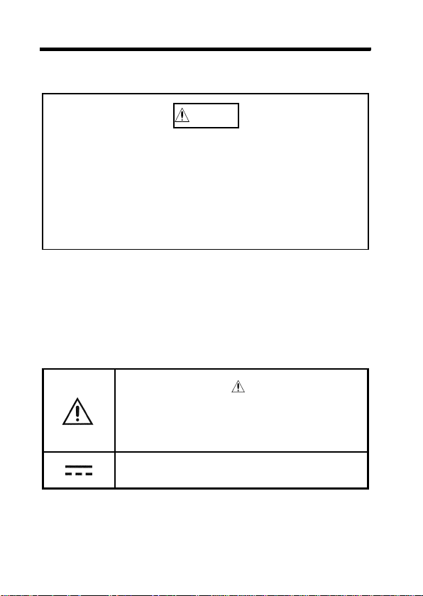
Safety symbols
In the manual, the symbol indicates
particularly important information that the
user should read before using the
product.
Indicates DC (Direct Current).
――――――――――――――――――――――――
Safety Notes
Page 7
―――――――――――――――――――――――――――
iii
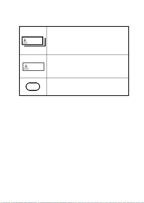
The following symbols in this manual indicate the
relative importance of cautions and warnings.
Indicates that incorrect operation
WARN ING
presents a significant hazard that could
result in serious injury or death to the
user.
Indicates that incorrect operation
CAUTION
presents a possibility of injury to the
user or damage to the product.
NOTE
Advisory items related to performance
or correct operation of the product.
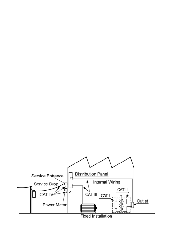
Measurement categories (Overvoltage
categories)
To ensure safe operation of measurementproducts,
IEC 61010 establishes safety standards for various
electrical environments, categorized as CAT I to
CAT IV, and called measurement categories. These
are defined as follows.
CAT I: Secondary electrical circuits connected to an
AC electrical outlet through a transformer or
similar device.
CAT II: Primary electrical circuits in equipment
connected to an AC electrical outlet by a
power cord (portable tools, household
appliances, etc.)
CAT III: Primary electrical circuits of heavy
――――――――――――――――――――――――
Safety Notes
Page 8
iv
―――――――――――――――――――――――――――
equipment (fixed installations) connected
directly to the distribution panel, and feeders
from the distribution panel to outlets.
CAT IV: The circuit from the service drop to the
service entrance, and to the power meter and
primary overcurrent protection device
(distribution panel).
Higher-numbered categories correspond to electrical
environments with greater momentary energy. So a
measurement device designed for CAT III
environments can endure greater momentary energy
than a device designed for CAT II.
Using a measurement product in an environment
designated with a higher-numbered category than
that for which the product is rated could result in a
severe accident, and must be carefully avoided.
Never use a CAT I measuring product in CAT II,
III, or IV environments.
The measurement categories comply with the
Overvoltage Categories of the IEC60664 Standards.
――――――――――――――――――――――――
Safety Notes
Page 9
―――――――――――――――――――――――――――
Notes on Use
Follow these precautions to ensure safe operation
and to obtain the full benefits of the various
functions.
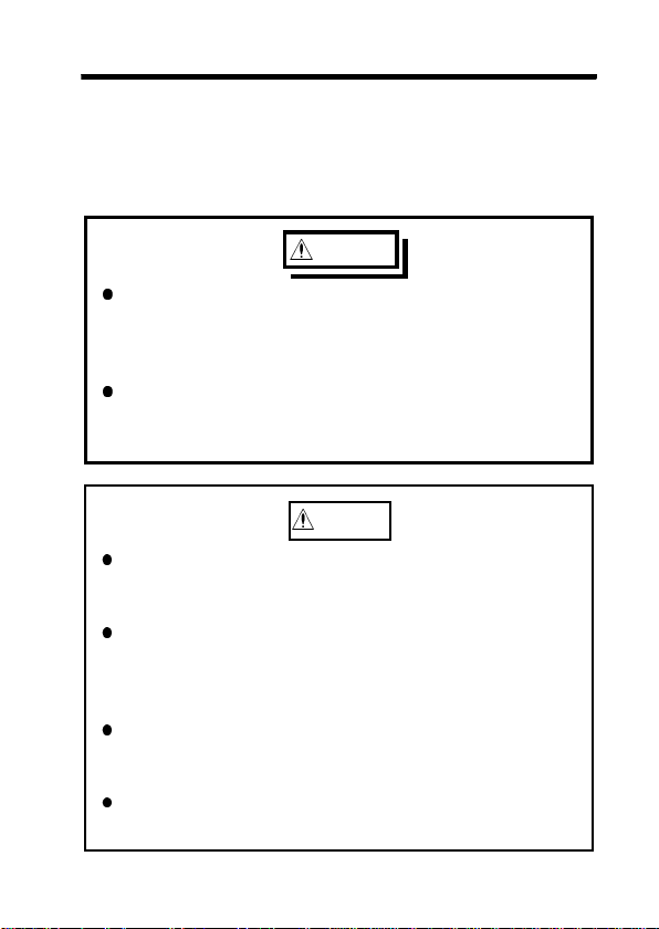
WARNING
Do not use the product where it may be
exposed to corrosive or combustible gases.
The product may be damaged or cause an
explosion.
To avoid electric shock, do not allow the
product to get wet, and do not use it when your
hands are wet.
CAUTION
To avoid system damage and malfunction by
making sure that the object to be measured does
not touch the system.
Do not touch the lens with a hard object, apply
undue pressure to the lens, or insert a foreign
substance in the unit. These actions will cause
system damage or malfunction.
Do not point the lens at the sun or at any other
source of strong light. If you do, the sensor may
be damaged.
Do not touch the LCD screen surface, since doing
so may cause erroneous display or distortion.
v
――――――――――――――――――――――――
Notes on Use
Page 10
vi
―――――――――――――――――――――――――――
CAUTION
To avoid damage to the product, protect it from
vibration or shock during transport and handling,
and be especially careful to avoid dropping.
Do not store or use the product where it could be
exposed to direct sunlight, high temperature or
humidity, or condensation. Under such conditions,
the product may be damaged and insulation may
deteriorate so that it no longer meets
specifications.
This product is designed for indoor use, and
operates reliably from 0
to 40 .
This product is not designed to be entirely water- or
dust-proof. To avoid damage, do not use it in a
wet or dusty environment.
Do not use the product near a device that
generates a strong electromagnetic field or
electrostatic charge, as these may cause
erroneous measurements.
If the protective functions of the product are
damaged, either remove it from service or mark it
clearly so that others do not use it inadvertently.
Do not disassemble or modify the system, since
doing so may prevent the system from satisfying
the specifications.
――――――――――――――――――――――――
Notes on Use
Page 11

―――――――――――――――――――――――――――
NOTE
Accurate measurement may be impossible in the
presence of strong magnetic fields, such as near
vii
transformers and high-current conductors, or in the
presence of strong electromagnetic fields such as
near radio transmitters.
If the set emissivity differs from the emissivity of
the object, a measurement error may result.
To avoid corrosion from battery leakage, remove
the batteries from the product if it is to be stored
for a long time.
To avoid problems with battery operation, remove
the batteries from the product if it is to be stored
for a long time.
――――――――――――――――――――――――
Notes on Use
Page 12

viii
―――――――――――――――――――――――――――
――――――――――――――――――――――――
Notes on Use
Page 13

―――――――――――――――――――――――――――
Chapter 1
Summary
1.1 Product Summary
1. Theory of Measurement
Every object emits infrared energy in accordance
with its temperature. By measuring the amount of
this radiant energy, it is possible to determine the
temperature of the emitting object.
2. About infrared
Infrared radiation is a form of light (electromagnetic
radiation), and has the property that it passes easily
through air, while it is easily absorbed by solid
matter.
With 3460-50 2D THERMO HiTESTER, accurate
measurement is possible, irrespective of the air
temperature or the measurement distance.
3. Emission Thermometer Structure
Infrared radiation which has been emitted from the
object is focused upon an infrared radiation sensor,
via an optical system which includes a lens which is
transparent to infrared radiation, an 8μm cuton
filter, etc..
1
The output signal from the infrared radiation sensor
is input to an electronic circuit along with the
output signal from a standard temperature sensor.
――――――――――――――――――――――――
Chapter 1 Summary
Page 14

2
―――――――――――――――――――――――――――
The electronic circuit calculates the object
temperature while applying standard temperature
compensation, thermal emissivity compensation,
etc., and displays the result.
1.2 Characteristic
Measures two-dimensional temperature using the
thermopile array (8 x 8 elements)
Equipped with a 3.8-inch color LCD
Built-in CMOS camera enables simultaneous display
of temperature image and optical image on a screen.
Compact and lightweight
Data stored on a compact flash card
The temperature alarm helps detect abnormal
temperatures.
Provided with an NTSC video terminal; images can
be recorded on a video recorder (video cable
available as an option).
Logging function and alarm function are available.
Temperatures can be recorded, monitored, and
alarms sent by connecting to a PC and creating a
program. (Interface cable is supplied separately.)
――――――――――――――――――――――――
Chapter 1 Summary
Page 15
―――――――――――――――――――――――――――
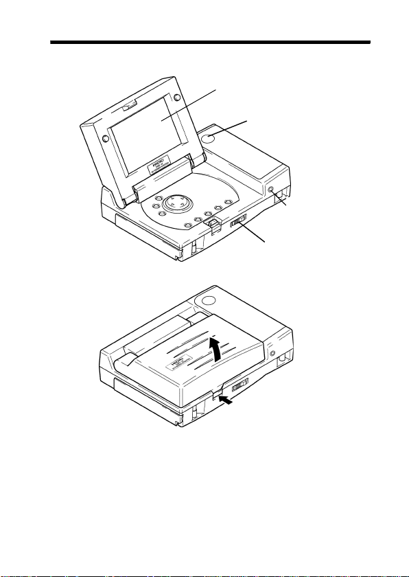
1.3 Names of Parts
Whole
LCD display
REC button
Power switch
Push and open
Interface
terminal
3
――――――――――――――――――――――――
Chapter 1 Summary
Page 16
4
―――――――――――――――――――――――――――
Front
Measurement/
hold button (HOLD)
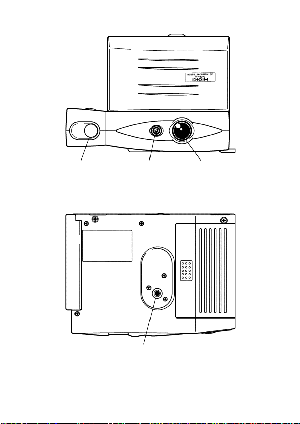
Bottom
――――――――――――――――――――――――
Chapter 1 Summary
Visible camera lens Infrared lens
Screw hole for
camera tripod
Battery cover
Page 17
―――――――――――――――――――――――――――
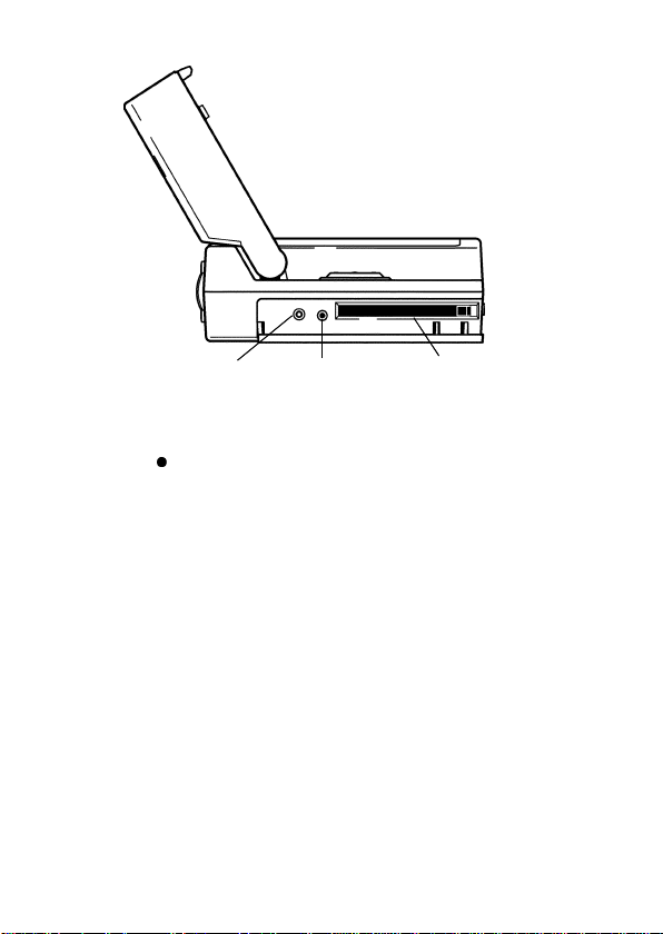
Side
5
Exclusive use
AC adapter
input terminal
Video Output
Terminal
Compact flash card
slot
[Video Output Terminal]
The terminal outputs the same video signals as those
output to the LCD screen. To view the images on a
TV, use the optional cable to connect this terminal
to the TV monitor input terminal. The video image
size is 1/4 of a full screen.
The cable and AC adapter are included within the
3915 OPTION PACK.
Make sure the power is turned off before connecting
or disconnecting the AC adapter.
――――――――――――――――――――――――
Chapter 1 Summary
Page 18
6
―――――――――――――――――――――――――――
WARNING
To avoid damage, turn the product off before
connecting the AC adapter to the product and
to AC power.
Use only the AC adapter supplied with Model
3915 OPTION PACK. AC adapter input voltage
range is 100 to 240 VAC (with 10% stability) at
50/60 Hz. To avoid electrical hazards and
damage to the product, do not apply voltage
outside of this range.
Make sure the power is turned off before
connecting or disconnecting the AC adapter.
NOTE
To ensure proper system operation, do not use the
AC adapter with an unstable power supply. In
particular, be careful about the mixing-in of impulse
components.
――――――――――――――――――――――――
Chapter 1 Summary
Page 19
―――――――――――――――――――――――――――
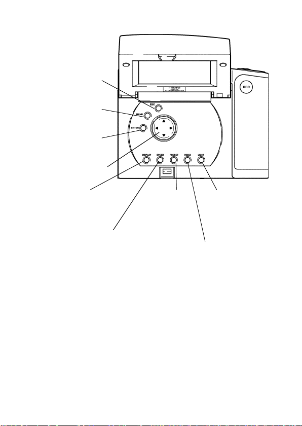
LCD display,
operation panel
Cancel Button
(ESC)
Menu Button
(MENU)
Input Button
(ENTER)
Cursor Button
7
Display Selector
Button (DISPLAY)
Measurement Speed
Selector Button
(SPEED)
Measurement
Condition
Selector Button
(PRESET)
――――――――――――――――――――――――
Backlight
Brightness
Setting Button
(LIGHT)
Index Display Button
(INDEX)
Chapter 1 Summary
Page 20
8
―――――――――――――――――――――――――――
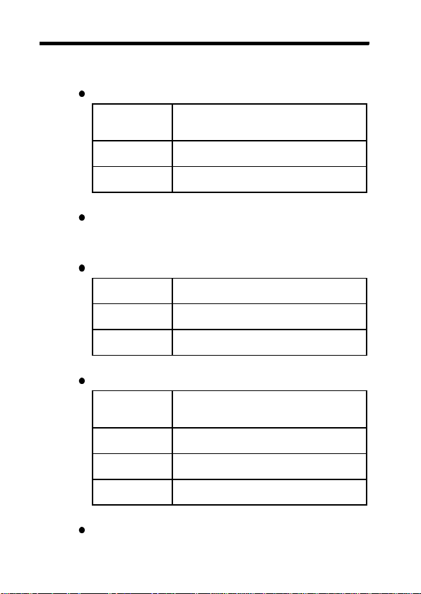
1.4 Switches and Controls
Input Button (ENTER)
During
Measurement/
Hold
During
Menu Screen
During
Index Screen
Menu Button (MENU)
Displays the menu for option settings.
Cancel Button (ESC)
During
Menu Screen
During
Setting Screen
During
Index Screen
Cursor Button
During
Measurement/
Hold
During
Menu Screen
During
Setting Screen
During
Index Screen
Set distance to object. (see page 22)
Use the cursor button to enter the
setting screen of the menu option.
Displays full-screen the image data
selected with the cursor button.
Returns to the measurement mode.
Returns to the menu screen with
confirming the setting.
Deletes the image data selected with
the cursor.
Use the cursor button to choose a
measurement point for which
numeric data must be displayed.
Use this screen to choose a setting
option.
Use this screen to choose an option
or edit the setting.
Selects image data.
Display Selector Button (DISPLAY)
Chooses a display mode (see page 21).
――――――――――――――――――――――――
Chapter 1 Summary
Page 21

―――――――――――――――――――――――――――
Measurement Speed Selector Button (SPEED)
Chooses a temperature measurement speed.
The resolution for high speed measurement is 1
NORMAL Display resolution is 0.1 . You can
FAST Display resolution is 1 .Moving
select a function that displays a
moving average for 10 data points,
or approx. 2 seconds of
measurements.
average is not available.
.
Measurement Condition Selector Button
(PRESET)
Selects a set of preset measurement conditions
including emissivity, scale, and alarm. The settings
for each preset are edited in the PRESET setting
screen. To go to the setting screen, enter the setting
mode (SETTING) and select the measurement
condition (PRESET) in the menu.
Index Display Button (INDEX)
Enters the index display mode and displays a list of
recorded image data.
Backlight Brightness Setting Button (LIGHT)
Adjusts the brightness of the LCD backlight (4
adjustable levels from no light to maximum
brightness).
When brightness is set to maximum, if no key
operation occurs for approximately 10 seconds,
brightness is automatically reduced to intermediate
or minimum settings (depending on the power
9
――――――――――――――――――――――――
Chapter 1 Summary
Page 22

10
―――――――――――――――――――――――――――
supply conditions).
Brightness cannot be set to the maximum setting
when the battery indicator indicates "Replace."
During automatic data recording, brightness is set to
the minimum setting.
Hold Button (HOLD)
The image is held on the LCD by pressing hold
button. (See page 4)
Record Button (REC)
Save the temperature data to the compact flash card.
(See page 3 and 24)
――――――――――――――――――――――――
Chapter 1 Summary
Page 23

―――――――――――――――――――――――――――
11
Chapter 2
Prior to Use
Prior to operating the thermometer, carry out the
following:
1. Attaching the strap
Attach the strap to the instrument to help prevent its
being dropped.
2. Loading the battery
Place the battery correctly in the battery box at the
back of main body.
For loading the battery, see page 14 "5. Battery
replacement".
3. Setting the date and time
When using the unit after replacement of the
battery, set the date and time. (See page 31)
――――――――――――――――――――――――
Chapter 2 Prior to Use
Page 24

12
―――――――――――――――――――――――――――
4. Installation of Compact Flash Card
CAUTION
Inserting a compact flash card upside down,
backwards or in the wrong direction may damage
the product.
Open the cover on the side of the system and insert the
compact flash card into the slot. Make sure that the
card faces in the correct direction and is fully inserted.
Compact Flash Card
The card stores image data and transfers data to a PC and
PDA (personal digital assistant) without special software.
Image: JPEG format
Measurement: CSV format
The system supports an 16-1 GB compact flash
cards ranging from 16 to 1 GB.
――――――――――――――――――――――――
Chapter 2 Prior to Use
Page 25

―――――――――――――――――――――――――――
WARNING
13
Use only PC Cards (Compact flash cards) sold by
HIOKI. Compatibility and performance are not
guaranteed for PC cards (Compact flash cards)
made by other manufacturers. You may be unable
to read from or save data to such cards.
Hioki options PC cards (includes adapter)
9726 PC CARD 128M, 9727 PC CARD 256M
9728 PC CARD 512M, 9729 PC CARD 1G
NOTE
An adapter is required to use a compact flash card
in the PC card slot of a PC.
To avoid data save or read errors, do not remove
the card when data is being saved or read. The
card can be inserted or removed at any time unless
data is being saved or read.
――――――――――――――――――――――――
Chapter 2 Prior to Use
Page 26

14
―――――――――――――――――――――――――――
5. Battery replacement
WARNING
To avoid electric shock, turn off the power
switch and disconnect the connection cables
before replacing the batteries.
Do not mix old and new batteries, or different
types of batteries. Also, be careful to observe
battery polarity during installation. Otherwise,
poor performance or damage from battery
leakage could result.
Attempting to charge alkaline batteries may
cause them to explode.
To avoid the possibility of explosion, do not
short circuit, disassemble or incinerate
batteries.
Handle and dispose of batteries in accordance
with local regulations.
NOTE
――――――――――――――――――――――――
Chapter 2 Prior to Use
The batteries are not pre-installed in the system.
Install the batteries as shown in the illustration.
Page 27

―――――――――――――――――――――――――――
NOTE
The supplied batteries are designed for a display
monitor. Thus, battery life may be short.
15
Do not use manganese batteries; use only alkaline
batteries.
Reset the system clock after replacing the batteries
(page 31).
To avoid corrosion from battery leakage, remove
the batteries from the product if it is to be stored
for a long time.
5. Battery Indicator
Remaining battery power is indicated in three levels
on the LCD.
When "Replace" is displayed, replace the batteries
immediately.
Normal Low Replace
NOTE
When "Replace" starts flashing, power will be shut
off within 5 minutes.
When "Replace" is displayed, the backlight
brightness cannot be set to maximum.
If you continue to use the tester after "Replace"
appears, either by switching to the AC adapter or
reducing backlight brightness, make sure that
temperature measurements are updated.
――――――――――――――――――――――――
Chapter 2 Prior to Use
Page 28

16
―――――――――――――――――――――――――――
――――――――――――――――――――――――
Chapter 2 Prior to Use
Page 29

―――――――――――――――――――――――――――
)
)
17
Chapter 3
Making
Measurements
3.1 Measurement Screen
tored
mage
esolution
Battery
indicator
No. of shots
taken/
No. of shots
remaining Date Time
Color scale
(upper limit
Alarm
setting
(upper limit
Alarm
setting
(lower limit)
Color scale
(lower limit)
Distance
Selected
frame
temperature
Example of a color frame display
――――――――――――――――――――――――
Measurement
speed
Measurement
condition
Chapter 3 Making Measurements
Status
Page 30

18
―――――――――――――――――――――――――――
Battery Indicator
Indicates the remaining battery power in three
levels.
When
is displayed, replace the batteries
immediately.
Number of Shots Taken/Number of Shots
Remaining
Indicates the number of shots remaining according
to the space remaining on the compact flash card.
The number of shots remaining is an estimate. The
actual number may be smaller or larger than the
number shown, as the size of data varies with
objects to measure. The maximum number of shots
remaining is 999.
Date/Time
Indicates date and time using the built-in clock.
Status
Indicates the operating status.
HOLD: Holding the image
MEAS: Performing measurement
REC: Performing the record
AUTO: Performing the record of data Automatically
WAIT: Waiting for start of automatic data recording
Color Scale Upper Limit Temperature
Indicates the upper limit temperature of the preset
selected with the PRESET button.
Color Scale Lower Limit Temperature
Indicates the lower limit temperature of the preset
selected with the PRESET button.
Alarm Upper Limit Temperature
Sets the upper limit on the measurement condition
setting screen (PRESET). The upper limit is
marked on the side of the scale.
――――――――――――――――――――――――
Chapter 3 Making Measurements
Page 31

―――――――――――――――――――――――――――
19
Alarm Lower Limit Temperature
Sets the lower limit on the measurement condition
setting screen (PRESET). This is marked on the
side of the scale.
Selected Frame Temperature
The selected frame is marked by a white cross
cursor. The cursor is moved up and down and right
and left with the cursor button.
Temperature Frame
Indicates the average temperature in the frame with
a color from the color scale.
Measurement Speed
Indicates the selected response speed. There are two
speed modes: high-speed mode (FAST) and
standard speed mode (NORMAL).
Measurement Condition
Indicates the measurement condition No. (1 to 3)
selected with the PRESET button.
Color Scale
This is a temperature color scale used for a frame or
mosaic display. There are three display patterns
available. Enter the setting mode (SETTING),
select COLOR SCALE in the menu, and choose a
display pattern from the COLOR SCALE setting
screen.
Stored Image Resolution
Sets the resolution of an image file. Select between
QVGA (320 x 240) and VGA (640 x 480). (page
24)
Distance
Sets the distance from the object to be measured.
Select between 0.5 m (0.5), 1.0 m (1.0), and 2.0 m
& over (
――――――――――――――――――――――――
). (page 22)
Chapter 3 Making Measurements
Page 32

20
―――――――――――――――――――――――――――
3.2 Measurement
(1) Turn on power
Open the LCD and slide the power switch to the
right. Following the opening screen, the visible
image, temperature data, and other information will
appear on the screen.
NOTE
After the power switch is moved to the ON
position, the LCD will first display a blue screen,
then the opening screen.
On any one occasion, slide the power switch to the
On position only once. Do not slide it back and
forth. If power does not turn on when you first slide
the switch to the On position, see Chapter 7 (P50).
――――――――――――――――――――――――
Chapter 3 Making Measurements
Page 33

―――――――――――――――――――――――――――
21
(2) Choose display mode
Choose a display mode using the Display Selector
button (DISPLAY).
Visible image only
Temperature
mosaic color display
Temperature frame
color display
――――――――――――――――――――――――
Chapter 3 Making Measurements
Page 34

22
―――――――――――――――――――――――――――
(3) Set distance to object
Press the input button (ENTER) and select a
distance to the object to be measured. Select from
0.5 m (0.5), 1.0 m (1.0), and 2.0 m & over ( ),
whichever most closely matches the actual distance.
(4) Measure temperature
(In the temperature frame color display mode or the
temperature mosaic color display mode)
Point the lens at the object. A visible image of the
object and the temperature measurement appear on
the screen. While the system is measuring, the
MEAS indicator is shown at the bottom right-hand
portion of the screen.
Press the measurement/hold button (HOLD)tohold
the image on the screen to the bottom right-hand
portion of the screen. Press the measurement/hold
button (HOLD) once again to release the image and
to display measurement results.
The temperature of the measuring point selected
with the cursor button is displayed at the bottom
left-hand portion of the screen.
――――――――――――――――――――――――
Chapter 3 Making Measurements
Page 35

―――――――――――――――――――――――――――
NOTE
If the emissivity is not set to the emissivity of the
object, the system will not display the correct
23
measurement results.
(See "Emissivity Table" on page 52 and
"Measurement Condition Setting" on page 30.)
When the emissivity of the object is low, the
thermal radiation from nearby heat sources may be
reflected on the measured surface, causing
measurement errors. Move the heat sources away
or shade the object from the heat sources.
When the distance to the object is set to 2.0 m &
over (
), the 3460-50's two optical axes are
parallel, parallax (the displacement between the
visual image optical axis and the optical axis of the
temperature sensor unit) is independent of the
distance from the measurement target, and is 26
mm in the horizontal direction and 0 mm in the
vertical direction.
(5) Turn off power
Slide the power switch to the right again.
When the Auto Power Off (page 32) is enabled
(ON), if the system has been idle for one minute,
power will be automatically turned off.
――――――――――――――――――――――――
Chapter 3 Making Measurements
Page 36

24
―――――――――――――――――――――――――――
3.3 Storage Image and Temperature
Data
Simultaneously press the cancel button (ESC) and
the input button (ENTER) to select between QVGA
(320 x 240) and VGA (640 x 480) for window size.
3.3.1 Measurement with Record Button
The image is held on the LCD by pressing the hold
button (HOLD). Press the record button (REC)for
saving the temperature data to the compact flash
card.
3.3.2 Logging Recording
You can set the system to perform automatic
logging. Set the recording start and end times.
(page 33)
――――――――――――――――――――――――
Chapter 3 Making Measurements
Page 37

―――――――――――――――――――――――――――
25
3.3.3 Storage File
ThefileextensionfortheimagedatafileisJPG.The
file extension for the temperature data file is CSV.
Image data is saved to the PICT folder, list of image
data is saved to the IPICT folder, while temperature
data is saved to the DATA folder.
Image : PICTxxxx.JPG
PICT0001.JPG
Each temperature data : DATAxxxx.CSV
DATA0001.CSV
Cumulative data : LOGDATA.CSV
LOGDATA.CSV
Image data files are paired with corresponding data files.
A new data file is named by incrementing the
number assigned for the previous data filename by
1. If no data file exists, the new data file is
assigned the name DATA0001.CSV.
If the last data file is DATA9999.CSV, the new data
file will be assigned the name DATA0001.CSV.
The images are recorded as shown on the screen.
The size of an image file is approximately 90 KB.
This may vary slightly from image to image and
from object to object. The supplied 16 MB card
will hold about 100 to 200 image and data files.
The data can be transferred to a PC using a
commercially-available compact flash card adapter.
The image data can be viewed in Internet
Explorer
(note1)
or other browser software.
(note1) Internet Explorer is a registered trademark of Microsoft
Corporation (USA).
――――――――――――――――――――――――
Chapter 3 Making Measurements
Page 38

26
―――――――――――――――――――――――――――
Temperature data can be read in EXCEL
(note2)
or
other software. You can copy or delete this data on
a PC.
3.3.4 CSV File Data
The CSV files store the following data:
Each image data: CSV file
Year/month/day, hour:minute:second, CH1
measurement --- CH64 measurement
2001/10/15, 11:55:36, 1000.0, 985.5, --- 123.4
Cumulative data: CSV file
No., year/month/day, hour:minute:second, CH1
measurement --- CH64 measurement
1, 2001/10/15, 11:55:36, 1000.0, 985.5, --- 123.4
2, 2001/10/15, 12:12:55, 856.3, 732.5, --- 55.8
Each channel corresponds to an individual
temperature display frame, as shown below.
(note2) Excel is a trademarks of Microsoft Corporation (USA).
――――――――――――――――――――――――
Chapter 3 Making Measurements
Page 39

―――――――――――――――――――――――――――
27
3.4 View Saved Images
Press the INDEX button to view a list of saved
images. Select an image in the list by using the
cursor button, then press the ENTER button. The
selected image will then be enlarged. Press the
ESC button to return to the list.
To delete an image, select an image, press the ESC
button, then press the ENTER button. Press the
DISPLAY button or INDEX button to return to
measurement mode.
NOTE
When many images are recorded (involving several
tens of files), it may take more time to read the
images.
――――――――――――――――――――――――
Chapter 3 Making Measurements
Page 40

28
―――――――――――――――――――――――――――
――――――――――――――――――――――――
Chapter 3 Making Measurements
Page 41

―――――――――――――――――――――――――――
29
Chapter 4
Setting
Press the MENU button to enter the setting mode
(SETTING). To return to measurement screen,
press the ESC button.
Choose a setting option using the up/down cursor
button.
The following setting options are available:
PRESET (measurement conditions)
You can register up to 3 combinations of color scale
temperature range, emissivity, and alarm
upper/lower limits.
CLOCK (time setting)
Set the time and choose the clock display pattern.
――――――――――――――――――――――――
Chapter 4 Setting
Page 42

30
―――――――――――――――――――――――――――
AUTO MODE (automatic data recording setting)
Enter the settings for the logging recording.
COLOR SCALE
Choose a color scale to display.
4.1 Measurement Condition Setting
(PRESET)
This is used to edit the settings of the measurement
condition presets 1 to 3. Select PRESET in the
menu and press ENTER to enter this screen.
Set SCALE (color scale temperature range), ε
(emissivity), and ALARM (alarm upper/lower
limits).
Move a cursor to the digit place you want to edit
using the right/left cursor button.
Increase or decrease the number using the up/down
cursor button.
――――――――――――――――――――――――
Chapter 4 Setting
Page 43

―――――――――――――――――――――――――――
The alarm upper/lower limits may be selected within
the measurement temperature range. The upper
limit must be greater than the lower limit.
The presets set on this screen are selected with the
measurement condition selector button (PRESET).
Press the ESC button to return to the Menu screen
(SETTING).
<Setting Range>
SCALE, ALARM : -50 to 1000
ε : 0.10 to 1.00 by every 0.01
by every 1
31
4.2 Clock
This sets date and time for the built-in clock and
auto power off function. Select CLOCK from the
menu and press ENTER to enter this screen.
Choose DATE/TIME (clock date and time),
DISPLAY STYLE (display pattern), or AUTO
POWER OFF.
――――――――――――――――――――――――
Chapter 4 Setting
Page 44

32
―――――――――――――――――――――――――――
The confirmed setting is shown in red.
Press the ESC button to return to the Menu screen
(SETTING).
4.2.1 Set DATE/TIME (clock date and time)
Move the cursor to DATE/TIME using the right/left
cursor button. Select the decimal place to be edited
using the right/left cursor button. Increase or
decrease the number by using the up/down cursor
button.
4.2.2 DISPLAY STYLE (display pattern)
Move the cursor to DISPLAY STYLE using the
right/left cursor button.
Choose 1 or 2 for the display pattern (DISPLAY
STYLE) using the up/down cursor button.
4.2.3 Set AUTO POWER OFF
Move the cursor to AUTO POWER OFF using the
right/left cursor button.
To set AUTO POWER OFF, choose between ON
and OFF using the up/down cursor button.
When the Auto Power Off is enabled (ON) and the
system has been idle for one minute, power will
automatically be turned off. To turn power on
again, slide the power switch to the right as in the
regular operation procedure.
――――――――――――――――――――――――
Chapter 4 Setting
Page 45

―――――――――――――――――――――――――――
33
4.3 Automatic Data Recording
(Logging) Measurement (AUTO
MODE)
This sets the time to start measurement (START),
the time to end measurement (END), and the
measurement interval (INTERVAL) for logging
measurements.
When INTERVAL is set to 00:00, the system does
not perform logging measurement.
Select AUTO MODE in the menu and press
ENTER to enter this screen.
Set the conditions for automatic data recording.
Chosen setting is shown in red.
START : Start time (year/month/day/hour/minute)
END : End time (year/month/day/hour/minute)
INTERVAL : Measurement interval (hour/minute)
Move the cursor to the field you want to edit using
the right/left cursor button.
Increase or decrease the number using the up/down
cursor button.
――――――――――――――――――――――――
Chapter 4 Setting
Page 46

34
―――――――――――――――――――――――――――
When INTERVAL is set to 00:00, the system does
not perform automatic data recording.
SAVE DATA : Sets whether or not to save the
image.
1:ALL PICTURE : Save the image at every
recording.
2:FIRST PICTURE: Save the image at the start of
recording only.
3:FIRST AND LAST PICTURE:
Save the image at the start and
end of recording.
Choose from 1 to 3 using the up/down cursor
button.
<Default Setting>
START : The start time entered in this screen.
END : The end time entered in this screen.
INTERVAL : 00:00
SAVE DATA : 1: ALL PICTURE
Press the ESC button to return to the Menu screen
(SETTING).
Press the ESC button during automatic data
recording to return to measurement screen.
Press the menu button (MENU) view the setting for
automatic data recording on the SETTING (AUTO
MODE) screen. When the setting is being displayed,
data recording is suspended. Press the menu button
(MENU) to return to the measurement screen and
resume data recording.
――――――――――――――――――――――――
Chapter 4 Setting
Page 47

―――――――――――――――――――――――――――
35
4.4 Color Scale
This selects among three display patterns of the
color scale used for temperature color frame or
mosaic display.
Select COLOR SCALE in the menu and press
ENTER to enter this screen.
Choose a pattern using the up/down cursor button.
On the scale, the top is high and the bottom is low.
Press the ESC button to return to the Menu screen
(SETTING).
――――――――――――――――――――――――
Chapter 4 Setting
Page 48

36
―――――――――――――――――――――――――――
――――――――――――――――――――――――
Chapter 4 Setting
Page 49

―――――――――――――――――――――――――――
37
Chapter 5
Transfer Function
Temperature measurement data is sent from the
interface terminal on the main unit. Temperatures
can be recorded, monitored, and alarms sent by
connecting to a PC and creating a program.
NOTE
The data transfer function on the main unit is only
able to transmit temperature measurement data
repeatedly. The unit cannot be controlled via a PC
(e.g. to change settings) and it is not possible to
acquire camera image data.
5.1 Interface Specifications
Item Specifications Remarks
Output data Temperature measurement
Transmission
interval
Interface RS-232C No flow control
Signal SD、GND Transmission only;
Transfer format Asynchronous : 38400 bps
――――――――――――――――――――――――
data (fixed-length binary data)
0.2 s
Data bit : 8
Startbit :1
Stop bit : 2
Parity bit : None
Chapter 5Transfer Function
no reception
Page 50

38
―――――――――――――――――――――――――――
5.2 Connection
WARNING
Always turn both devices OFF when connecting
and disconnecting an interface connector.
Otherwise, an electric shock accident may occur.
To avoid damage to the product, do not shortcircuit the terminal and do not input voltage or
current to the terminal.
1. Insert the interface cable plug into the interface
terminal on the main unit.
2. Connect the interface cable RS-232C connector to
the PC COM port.
Interface
Interface
terminal
terminal
――――――――――――――――――――――――
Chapter 5Transfer Function
Page 51

―――――――――――――――――――――――――――
39
5.3 Transmission Data Format
5.3.1 Temperature Measurement Data
Temperature measurement data is transmitted
repeatedly at intervals of approximately 200 ms
while measurement is in progress. Data is sent each
time as 133-byte fixed length binary data.
1st byte Header Measurement successfully
2nd byte Emissivity setting
3rd/4th bytes Sensor
5th-132nd bytes Temperature
133rd byte Check sum Last 8 bits of sum from 1st to
×
100
temperature
measurement results
completed
Invalid data
Not calibrated - Measurement
not possible
Data error - Calculation
not possible
64H for setting 1.00
2 bytes (first byte first)
2 bytes×64 points
132nd byte
Sensor temperatures and temperature measurements are
expressed as 2-byte data. Details are as shown below.
Sensor temperature,
temperature measurement
0000 Invalid temperature data (e.g. measurement
0001〜FFFEH Temperature (Celsius)×50+4096
FFFFH Data error (error occurred during
Status, conversion formula
results have not been saved)
measurement or calculation)
Example: 0℃→a Internal data 1000H
1000℃→ a Internal data D350H
:
20H
:
21H
:
22H
:
23H
――――――――――――――――――――――――
Chapter 5Transfer Function
Page 52

40
―――――――――――――――――――――――――――
5.3.2 Data Timing
200 msec
→
Power O N
Data
1st 2nd
n
n+1st
Temperature measurement data (133 bytes) is
transmitted automatically at 200 ms intervals.
Transmission of temperature measurement data takes
approximately 40 ms.
Measurement data is sent repeatedly, so the header
data must first be detected before receiving the
following 133 bytes to process the data. The header
data cannot be detected if it is not distinct from the
temperature measurement data. Processing is
therefore required to cope with this situation, such
as clearing the receipt buffer if no data is received
within a preset time interval.
――――――――――――――――――――――――
Chapter 5Transfer Function
Page 53

―――――――――――――――――――――――――――
41
5.4 Temperature Measurement Result
Sequence and Measurement Location
Each measurement data transmission contains 64
temperature measurement results. The sequence and
measurement locations are as shown below.
Measurement surface
upper
AB CD E F G H
8
57 49 41 33 25 17 9 1
7
58 50 42 34 26 18 10 2
6
59 51 43 35 27 19 11 3
5
left
60 52 44 36 28 20 12 4
4
61 53 45 37 29 21 13 5
62 54 46 38 30 22 14 6
3
63 55 47 39 31 23 15 7
2
1
64 56 48 40 32 24 16 8
lower
right
The figures in the table indicate the temperature
data transmission sequence.
――――――――――――――――――――――――
Chapter 5Transfer Function
Page 54

42
―――――――――――――――――――――――――――
――――――――――――――――――――――――
Chapter 5Transfer Function
Page 55

―――――――――――――――――――――――――――
43
Chapter 6
Specification
6.1 Product Specification
Temperature Measurement
Detection element Thermopile array
Measurement range -50 to 1000
Sampling rate Approx. 0.2 seconds
Number of elements 64 (Horizontal 8 x vertical 8)
Measurement view
angle for one element
Measurement view
angle
Infrared wavelength 8to16μm
Radiation ratio
correction
Resolution 0.1
Accuracy 10%rdg. 2 (-50.0 to -0.1 )
Relative accuracy 1.0 (P-P, 23 )
Note 1: At the standard measurement speed (
3.1square (55 mm square at 1 m)
24.8 square (440 mm square at 1 m)
0.1 to 1.00 (steps of 0.01)
(Note 1)
2.0 (0.0 to 200.0 )
1%rdg. (200.1 to 1000.0 )
(Note 1)
NORMAL
)
Visual Photography
Detection element Color CMOS
Frame Time Approx. 0.5 seconds
Number of pixels Approx. 300,000 pixels (640 x 480)
Image angle Horizontal 50.0 x vertical 37.5
Smallest distance 0.5 m
Display
――――――――――――――――――――――――
(Horizontal 930 mm x vertical 680 mm
when the object is 1 m away)
Chapter 6 Specification
Page 56

44
―――――――――――――――――――――――――――
Display element Transmission type color TFT liquid
Size 3.8 inch
Number of pixels Approx. 76800 pixels (320 x 240)
Display colors 65535 colors (16-bit)
Backlight Cold cathode tube
Backlight brightness 3 adjustable levels + no light
Temperature indication
(each element)
Temperature indication
(selected element)
Parallax error 26 mm constant (Correction possibility
Optical axis deviation 1.15 or less
Functions
Temperature units
Logging measurement Specified in units of minutes (hh:mm)
Interval 00:01 to 24: 00
Measurement data
memory
Storage format JPEG file (image data, Definition 320 x
Battery remaining
indicator
Other functions Image data deletion, audible click,
crystal
Frame color display (Display range
and display pattern are selectable.)
Indicated by numerals
with software)
(20 mm when the object is 1 m away,
excluding parallax error)
Compact flash card (16 to 1 GB)
240, 640 x 480: Selection possibility)
CSV file (temperature value data)
3-level display
alarm/buzzer, automatic power off, clock
Basic Specifications
Data output RS-232C (Temperature data only)
Image output NTSC video output
Power source LR6 (AA) alkaline batteries x 6,
Rated power source
voltage
――――――――――――――――――――――――
Chapter 6 Specification
AC adapter (S-8392, KAGA
COMPONENTS) (3915 OPTION
PACK)
1.5 V DC x 6 (LR6),
9 V DC (Exclusive use AC adapter )
Page 57

―――――――――――――――――――――――――――
Maximum rated power 13.5 VA
Continuous operating
time
Dimensions Approx. 165W x 55H x 123D mm
Mass Approx. 700 g,
Accessories supplied LR6 (AA) alkaline batteries x 6, Strap,
Options 3915 OPTION PACK (Portable case,
Environment condition
Operating temperature
and humidity range
Storage temperature
and humidity range
Temperature and
humidity for
guaranteed accuracy
Guaranteed accuracy
period
Location for use Indoor
Standards applying
Safety
EMC
Approx. 70 minutes (intermediate
level, about 23
Approx. 6.57" W x 2.17" H x 4.84" D
(The main unit only with the LCD closed)
Approx. 24.7 oz. (excluding battery)
Compact flash card (16 MByte),
Instruction manual
Video cable, AC adapter) Serial
communication cable, Black body spray,
Black body tape, PC cards (compact
flash and PC card adapter set) (9726
PC CARD 128M, 9727 PC CARD 256M,
9728 PC CARD 512M, 9729 PC CARD
1G) , PC card adapter (for compact
flash card)
0to40 , 32 to 104
35 to 75% RH; no condensation
-20 to 50 , -4 to 122
80% RH or less; no condensation
23 5 ,73 9
35 to 75%RH; no condensation
1 year
EN61010
Pollution Digree 2
EN61326
EN61000-3-2
EN61000-3-3
)
45
――――――――――――――――――――――――
Chapter 6 Specification
Page 58

46
―――――――――――――――――――――――――――
6.2 Measurement Range
Measurement range
The measurement range is proportional to the
distance between the 3460-50 and the object.
――――――――――――――――――――――――
Chapter 6 Specification
Page 59

―――――――――――――――――――――――――――
47
Parallax error
Temperat ure M easurement Ran ge
of Object 1 m Distant
Temperature frame
on the screen
Actual temperature
measurement frame
Temperat ure M easurement Ran ge
of Object 10 m Distant
Temperature frame
on the screen
Actual temperature
measurement frame
The axes of the camera and the thermopile array are
26 mm apart from each other in parallel.
Parallax error may be ignored if the distance to the
object is set properly.
――――――――――――――――――――――――
Chapter 6 Specification
Page 60

48
―――――――――――――――――――――――――――
Measurement Area of Each Temperature
Element (distance: 1.0 m)
Temperature frame on the screen
Actual temperature measurement
range (maximum)
The measurement result shows the average
temperature in the measurement area.
This range assumes that the optical efficiency is
90%.
――――――――――――――――――――――――
Chapter 6 Specification
Page 61

―――――――――――――――――――――――――――
49
Chapter 7
Maintenance and
Service
7.1 Troubleshooting
If damage is suspected, check the "Troubleshooting"
section before contacting your dealer or Hioki
representative.
When sending the product for repair, remove the
batteries and pack carefully to prevent damage in
transit. Include cushioning material so the
instrument cannot move within the package. Be sure
to include details of the problem. Hioki cannot be
responsible for damage that occurs during shipment.
――――――――――――――――――――――――
Chapter 7 Maintenance and Service
Page 62

50
―――――――――――――――――――――――――――
Problem Cause Solution
No display /
Power does
not come
on
Measured
temperature
value
peculiar
Batteries are dead. Replace the batteries.
Backlight is set to
no light.
The internal circuit
is in a reset state
due to a drop in
voltage (including
temporary drops).
Lens dirty and
Adhesion of the
drop of water
There is a high heat
source nearby.
The thermal
emissivity value is
not appropriate.
Remaining battery
power is low.
The temperature of
the 3460-50 is
unstable.
Press the LIGHT button.
Disconnect the AC adapter
and remove the batteries.
Wait at least one minute,
then reconnect the adapter
and reinstall the batteries.
Clean the lens.
Move the heat source
away or shade the object
from the thermal radiation
of the heat source.
Set the thermal emissivity
to an appropriate value.
Replace the batteries.
Wait until the temperature
stabilizes.
――――――――――――――――――――――――
Chapter 7 Maintenance and Service
Page 63

―――――――――――――――――――――――――――
51
7.2 Maintenance
Infrared lens
The infrared lens is the most critical component for the
temperature measurements. A dirty lens may cause
measurement errors or shorten the life of the lens.
If the lens is dirty
Ifthelensisdirty,cleandustetc.offitusinga
camera lens cleaning tissue, blower or similar means.
Wipe off moisture with gauze or cotton swab.
If the lens is very dirty, clean it using a cotton bud
containing a small quantity of alcohol.
Body
To clean the product, wipe it gently with a soft
cloth moistened with water or mild detergent. Never
use solvents such as benzene, alcohol, acetone,
ether, ketones, thinners or gasoline, as they can
deform and discolor the case.
Wipe the LCD gently with a soft, dry cloth.
――――――――――――――――――――――――
Chapter 7 Maintenance and Service
Page 64

52
―――――――――――――――――――――――――――
7.3 Emissivity Table
When the emissivity of the object is low, the
readings may become unstable. In that case, use the
blackbody spray or blackbody tape available as
optional equipment.
Use the table below as a guide. Emissivity varies
depending on the smoothness of the surface and the
thickness of the material besides the material itself.
Substance
Thermal
emissivity
Asphalt 0.90 to 0.98 Charcoal
Concrete 0.94 Lacquer 0.80 to 0.95
Cement 0.96 Lacquer (matt) 0.97
Sand 0.90 Rubber (black) 0.94
Earth 0.92 to 0.96 Plastic 0.85
Water 0.92 to 0.96 Timber 0.90
Ice 0.96 to 0.98 Paper 0.70 to 0.94
Snow 0.83 Aluminium
Glass 0.90 to 0.95 Chromium
Ceramic 0.90 to 0.94 Copper oxides 0.78
Marble 0.94 Iron oxides 0.78 to 0.82
Fluorite 0.30 to 0.40 Nickel oxides 0.90
Plaster 0.80 to 0.90 Titanium
Mortar 0.89 to 0.91 Zinc oxides 0.11 to 0.28
Brick (red) 0.93 to 0.96 Brass oxides 0.56 to 0.64
Textiles 0.90 Uneven
Cloth (black) 0.98 Rolled
Human skin 0.98 Heavily rusted
Leather 0.75 to 0.80
――――――――――――――――――――――――
Chapter 7 Maintenance and Service
Substance
(powder)
oxides
oxides
oxides
bronze
surfaces
stainless steel
iron
Thermal
emissivity
0.96
0.76
0.81
0.40 to 0.60
0.55
0.45
0.69
Page 65

―――――――――――――――――――――――――――
53
7.4 Questions and Answers about
Measurement
Q: Why can't I measure the temperature on the other
side of a glass pane?
A: Normal glass absorbs infrared radiation of the
wavelength (8 to 16 μm) which this device uses for
temperature measurement. Therefore this device
cannot measure the temperature of an object on the
other side of a glass sheet, but instead measures the
temperature of the glass sheet itself.
Q: Light is shining on an object. Why can't I measure
its temperature accurately?
A: Since fluorescent light includes almost no infrared
radiation, it has almost no effect upon normal
temperature measurement. However sunlight and
incandescent lights emit radiation which includes
substantial amounts of the infrared radiation used by
this device for temperature measurement, and
accordingly may produce significant measurement
discrepancies.
――――――――――――――――――――――――
Chapter 7 Maintenance and Service
Page 66

54
―――――――――――――――――――――――――――
Q: Why can't I measure the temperature of a gas,
vapor, or flame?
A: Since gases, vapors, and flames are transparent to
infrared radiation, their temperatures cannot be
measured in this way.
Q: Why can't I measure temperature through rain or
fog?
A: Since rain and fog reflect and absorb infrared
radiation, accurate measurement through them is
impossible.
Q: Doesn't the measurement distance affect the
resulting measured value for temperature?
A: Air hardly absorbs at all infrared radiation of the
wavelengths (8 to 16 μm) used by this device for
temperature measurement. Therefore accurate
temperature measurement is possible, irrespective of
the measurement distance.
――――――――――――――――――――――――
Chapter 7 Maintenance and Service
Page 67

Page 68

Page 69

HIOKI 3460-50 2D THERMO HiTESTER
Instruction Manual
Publication date: December 2007 Revised edition 2
Edited and published by HIOKI E .E. CORPO RATION
Technical Support Section
All inquiries to International Sales and Marketing De-
partment
81 Koizumi, Ueda, Nagano, 386-1192, Japan
TEL: +81-268-28-0562 / FAX: +81-268-28-0568
E-mail: os- c om@hioki.co.jp
URL http://www.hioki.com/
Printed in Japan 3460C981-02
• All reasonable care has been taken in the production
of this manual, but if you find any points which are
unclear or in error, please contact your supplier or the
International Sales and Marketing Department at
HIOKI headquarters.
• In the interests of product development, the contents
of this manual are subject to revision without prior
notice.
• The content of this manual is protected by copyright.
No reproduction, duplication or modification of the
content is permitted without the authorization of Hioki
E.E. Corporation.
Page 70

HEAD OFFICE
81 Koizumi, Ueda, Nagano 386-1192, Japan
TEL +81-268-28-0562 / FAX +81-268-28-0568
E-mail: os-com@hioki.co.jp
URL http://www.hioki .c om/
HIOKI USA CORPORATION
6 Corporate Drive, Cranbury, NJ 08512, USA
TEL +1-609-409-9109 / FAX +1-609-409-9108
3460C981-02 07-12H
Printed on recycled paper
 Loading...