

Page 1
HIGH VOLTAGE
INSTRUCTION MANUAL
3455
INSULATION HiTESTER
www. .com
information@itm.com1.800.561.8187
Page 2

1
2
3
4
5
6
7
8
9
10
11
付録
索引
i
Contents
Introduction ...................................................... 1
Verifying Package Contents / Open the case ..1
Safety Infor ma tion ............ .. ........................... .. 5
Operating Precautions .....................................8
1 Overview 13
1.1 Product Overview .................................13
1.2 Features .............. ............. .............. ......15
1.3 Measure me nt Overview ......... .. ............17
1.4 Names and Functions of Parts .............24
1.5 Screen Setup .......................................28
2 Measurement Preparations 31
2.1 Supplying Power ..................................31
2.1.1 Installing or Replacing the Battery ......31
2.1.2 Installing the Battery Pack
(Rechargeable nickel-hydrogen battery) 34
2.1.3 Connecting the AC Adapter ................39
2.1.4 Charging the Battery Pack .................41
2.2 Turning Power On and Off ...................44
2.2.1 Auto Power Off ...................................45
2.3 Setting and Checking Date and Time ..46
2.3.1 Setting Date and Time ........................46
2.3.2 Checking Date and Time ....................49
2.4 Connecting Test Lead ..........................50
2.5 Connecting Temperature Sensor .........52
www. .com
information@itm.com1.800.561.8187
Page 3

ii
3 Measurement 53
3.1 Pre-Operation Inspection .....................53
3.2 Measuring Insulation Resistance .........56
3.2.1 Starting Measurement .........................58
3.2.2 Ending Measurement ..........................64
3.2.3 Checking and Deleting Held Data .......66
3.2.4 Automatic Discharge Function ............67
3.2.5 Switching to Leakage Current Indication 68
3.2.6 Insulation Resistance Measurement
Basis ...................................................69
3.2.7 Use of GUARD Terminal .....................71
3.3 Measuring Voltage ...............................73
3.4 Measuring Temperature .......................76
3.4.1 Measurement Procedure ....................76
4 Advanced Measurement 79
4.1 Using Time r .... .............. .............. ..........79
4.1.1 Setting Timer/Conducting Insulation
Resistance Measurement ...................79
4.2 Displaying PI and DAR .........................83
4.3 Temperature Correctio n ( T C ) ... ............87
4.3.1 Performing Temperature Correction ...88
4.3.2 Exiting Temperature Correction Mode 92
4.4 Step Voltage Test .................................93
4.4.1 Setting and Conducting a Step Voltage
Test .....................................................94
4.4.2 Viewing Detai led Da ta o f Each Ste p af ter
Step Voltage Test .......................... .....97
4.4.3 Exiting Step Voltage Test Mode ..........99
www. .com
information@itm.com1.800.561.8187
Page 4

1
2
3
4
5
6
7
8
9
10
11
付録
索引
iii
5 Recording Measurement Data
(Memory Function) 101
5.1 Recording Measurement Data ...........103
5.1.1 Manual Recording (Recording result
of one measurement session) ..........103
5.1.2 Logging Recording (Recording at
regular intervals) ...............................106
5.2 Checking Recorded Data ...................115
5.3 Deleting Recorded Data .....................120
5.3.1 Deleting Data of Chosen No. ............120
5.3.2 Deleting all Data ...............................121
6 Other Functions 123
6.1 Changing and Checking Interval Setting
for PI Calculation ................................123
6.1.1 Changing Interval Setting .................123
6.1.2 Checking Interval Setting .................125
6.2 Changing and Check i ng Vol tag e
Application Time for Step Voltage Test .126
6.2.1 Changing Time Setting ..................... 126
6.2.2 Checking Time Setting .....................128
6.3 Entering Temperature and Humidity
Measured with External Thermometer
and Hygrometer .................................129
6.3.1 Entering and Saving .........................130
6.3.2 Clearing Indications of Temperature
and Humidity Stored Data ................133
6.4 Communicating with PC ..................... 134
6.4.1 Installing Data Analysis Software for
3455 .................................................135
6.4.2 Installing Driver .................................136
6.4.3 Downloading Data to Save to PC/
Setting up Tester on PC ...................145
www. .com
information@itm.com1.800.561.8187
Page 5

iv
7 Specifications 147
7.1 General Specifications .......................147
7.2 Measurement Specifications .............. 152
7.2.1 Insulation Resistance Measurement .152
7.2.2 Leakage Current Measurement ........155
7.2.3 Voltage Measurement .......................156
7.2.4 Temperature Measurement ..............157
8 Maintenance and Service 159
8.1 Troubleshooting .................................160
8.2 Cleaning ............................................. 162
8.3 Error Display ......................................162
8.4 Performing System Reset ..................165
8.5 Discarding the Instrument ..................166
Appendix 169
Appendix 1 Test Voltage Characteristic
Graph ......................................169
Appendix 2 Example of Insulation Resistance
Criteria ..................................... 170
Appendix 3 Example of PI Criteria
(Polarization Index) ................. 170
Appendix 4 Temperature Correction Table 171
www. .com
information@itm.com1.800.561.8187
Page 6

Introduction
1
2
3
4
5
6
7
8
9
10
11
付録
索引
1
Introduction
Thank you for purchas i ng the HIOKI “Model
3455 HIGH VOLTAGE INSULATION HiTESTER” To obtain maximum performance
from the instrument, please read this manual first, and keep it handy for future reference.
• Windows and Internet Explorer are registered trademark of Microsoft Corp oration in
the United States and/or other countries.
• Adobe and Adobe Reader are registered
trademark of Adobe Systems Incorporated.
V erifying Package Contents / Open
the case
When you receive the instrument, inspect it
carefully to ensure that no damage
occurred during shipping. In particular,
check the accessories, panel switches, and
connectors. If da mage is evide nt, or if it f ails
to operate according to the specifications,
contact your dealer or Hioki representative.
Open the case by releasi ng the two latc hes.
(See next page.)
Registered trade mark
Open the case
Appearance of Case
Cover
Latches
Handle
www. .com
information@itm.com1.800.561.8187
Page 7

Verifying Package Contents / Open the case
2
Procedure
1. Draw the latch outwards with your fin-
ger.
2. While raising the entir e latch, place a
finger on the top of th e latch and pull
it out.
www. .com
information@itm.com1.800.561.8187
Page 8
Verifying Package Contents / Open the case
1
2
3
4
5
6
7
8
9
10
11
付録
索引
3
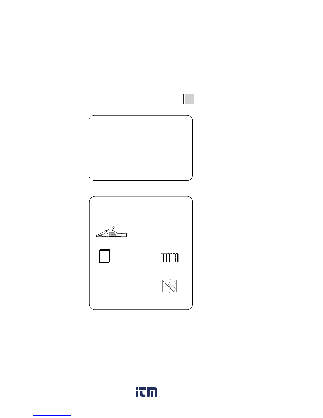
Main Unit
Accessories
3455 HIGH VOLTAGE INSULATION HiTESTER 1
9750-01,-02,-03 TEST LEAD (Red, Black, Blue)
Lead length Approx. 3 m 1 each
LR6 alkaline battery 6Instruction Manual
(This book) 1
USB Cable 1
9751-01,-02,-03 ALLIGATOR CLIP(Red, Black, Blue)
1 each
CD-R (Data Analysis
Software for 3455) 1
www. .com
information@itm.com1.800.561.8187
Page 9

Verifying Package Contents / Open the case
4
Options
9750-11,-12,-13 TEST LEAD
(Red, Black, Blue Lead length Approx. 10 m)
The specifications for the 9750-11 and
9750-12 models differ from the standard
specifications in regards to temperature
characteristics.
❖See 7.2"Measurement Specifications" (page
152).
9631-01,-05 TEMPERATURE SENSOR
Used for temperature measurement.
9631-01: Lead length Approx. 1 m
9631-05: Lead length Approx. 6 cm
9459 BATTERY PACK
(Rechargeable nickel-hydrogen battery)
The 9753 AC ADAPTER is required for
charging.
9753 AC ADAPTER
Input : 100 to 240 VAC
Output: 12 VDC 3.33 A
www. .com
information@itm.com1.800.561.8187
Page 10
Safety Information
1
2
3
4
5
6
7
8
9
10
11
付録
索引
5
Safety Information
Safety Symbols
This manual contains information and warnings essential for safe operation of the
instrument and for maintaining it in safe
operating conditi on. Before using it, be su re
to carefully read the following safety precautions.
The following symbols in this manual indicate the relative i mp or tance of cautions and
warnings.
This instruments designed to comply
with IEC 61010 Saf ety Standard s, an d has
been thoroughly tested for safety prior to
shipment. However, mishandling during
use could result in injury or death, as well
as damage to the instrument. Be certain
that you understand the instructions and
precautions in the manual before use. We
disclaim any responsibility for accidents
or injuries not resulting directly from
instrument defects.
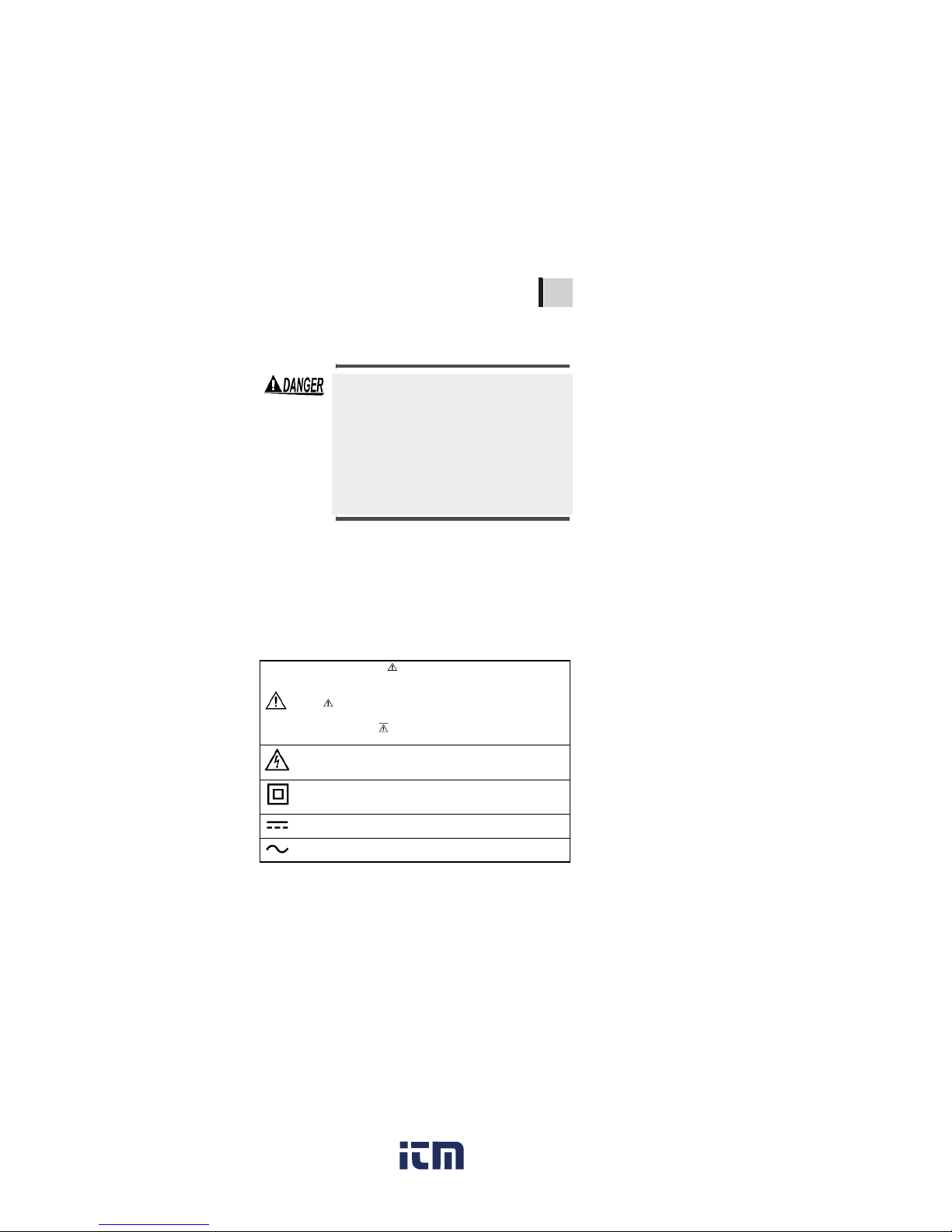
In the manual, the symbol indicates particularly important information that the user should read before using the
instrument.
The symbol printed on the instrument indicates that the
user should refer to a corresponding topic in the manual
(marked with the symbol) before using the relevant function.
Indicates that dangerous voltage may be present at this terminal.
Indicates a double-insulated device.
Indicates DC (Direct Current).
Indicates AC (Alternating Current).
www. .com
information@itm.com1.800.561.8187
Page 11
Safety Information
6
Other Symbols
Accuracy
We define measurement tolerances in
terms of rdg. (re ading) and dgt. (dig it) values, with the following meanings:
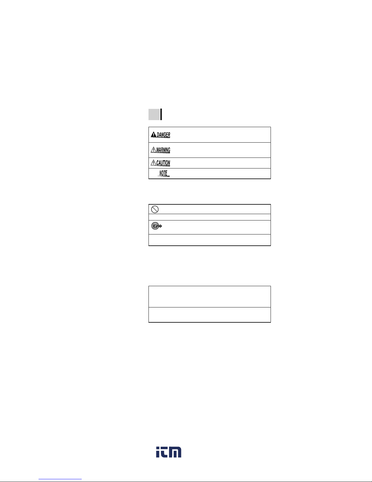
Indicates that incorrect operation presents an extreme
hazard that could result in serious injury or death to the
user.
Indicates that incorrect operation presents a significant
hazard that could result in serious injury or death to the
user.
Indicates that incorrect operation presents a possibility
of injury to the user or damage to the instrument.
Indicates advisory items related to performance or correct operation of the
instrument.
Indicates a prohibited action.
❖
Indicates the location of reference information.
Indicates quick references for operation and
remedies for troublesh oo t i ng .
*
Indicates that descriptive information is provided
below.
dgt.
(resolution)
The smallest displayable unit on a digital measuring instrument, i.e., the input value that causes
the digital display to show a "1" as the least-significant digit.
rdg. (reading
or displayed
value)
The value currently being measured and indicated on the measuring instrument.
www. .com
information@itm.com1.800.561.8187
Page 12
Safety Information
1
2
3
4
5
6
7
8
9
10
11
付録
索引
7
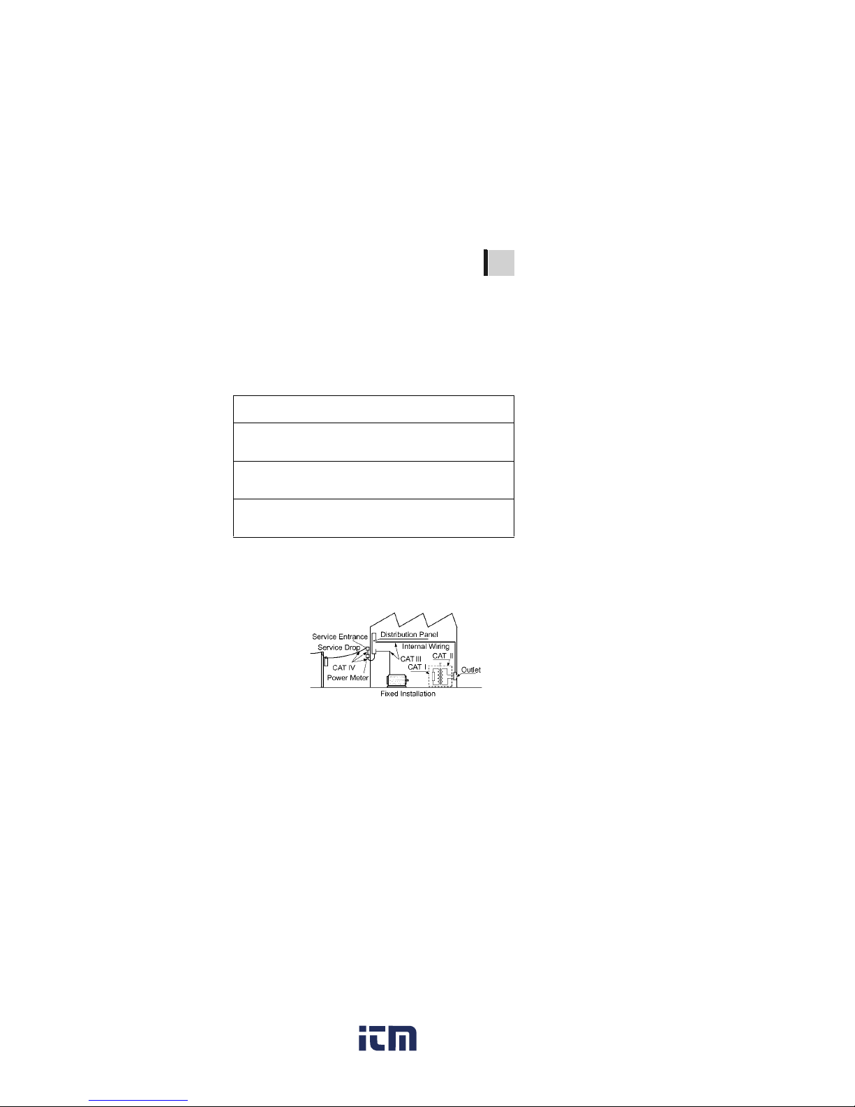
Measurement categories (Overvoltage categories)
This instrument complies with CAT IV (600
V), CAT III (1000 V) safety requirements.
To ensure safe operation of measurement
instruments, IEC 61010 establishes safety
standards for various electrical
environment s, categorized as CAT I t o CAT
IV, and called measurement categories.
These are defined as follows.
Higher-numbere d catego rie s cor res pond to
electrical envir onments with greater
momentary energy. So a measurement
device designed for CAT III environments
can endure greater momentary ene rgy than
a device desi gned for CAT II.
Using a measurement instrument in an
environment designated with a higher-numbered category than that for which the
instrument is rated could result in a severe
accident, and must be carefu l ly avoi de d.
Never use a CAT I measuri ng i nstrument in
CAT II, III, or IV environments.
The measurem ent categories comply with
the Overvoltage Categories of the
IEC60664 S tandards.
CAT I Secondary electrical circuits connected to an AC electri-
cal outlet through a transformer or similar device.
CAT II Primary electrical circuits in equipment connected to an
AC electrical outlet by a power cord (portable tools,
household appliances, etc.)
CAT III Primary electrical circuits of heavy equipment (fixed in-
stallations) connected directly to the distribution panel,
and feeders from the distribution panel to outlets.
CAT IV The circuit from the service drop to the service entrance,
and to the power meter and primary overcurrent protection device (distribution panel).
www. .com
information@itm.com1.800.561.8187
Page 13
Operating Precautions
8
Operating Precautions
Follow these precautions to ensure safe
operation and to obtain the full benefits of
the various functions.
Before using the instrument the first time,
verify that it operates normally to ensure
that the no damage occurred during storage or shipping. If you find any damage,
contact your dealer or Hioki representative.
Preliminary Checks
Before using the instrum ent, make sure
that the insulation on the test leads and
cables is undamaged and that no bare
conductors are improperly exposed.
Using the product in such conditions
could cause an electric shock, so contact
your dealer or Hioki representative for
replacements.
(Model 9750-01,-02,-03 TEST LEAD,
Model 9751-01,-02,-03 ALLIGATOR CLIP)
www. .com
information@itm.com1.800.561.8187
Page 14

Operating Precautions
1
2
3
4
5
6
7
8
9
10
11
付録
索引
9
• Operating t em pe rature and humidity:
0 to 40°C (32 to 104
°F
)
90%RH or less (no condensation)
• Temperature and humidity range for guaranteed accuracy:
Insulation resistance measurement / leakage current measurement
0 to 28°C (32 to 82
°F)
90%RH or less (no condensation)
Voltage measurement / temperature measurement
23±5°C (73± 9
°F)
90%RH or less (no condensation)
Placement
To avoid malfunctions and accidents, do not place the tester
where it will be exposed to any of the following:
•Direct
sunlight
•High
temperature
•Corrosive or
explosive gas
• Sprayed/
splashed
water
• High humidity
with
condensation
• Strong
electromagnetic fields
• Electrically
charged
objects
•Dust
• Mechanical
vibration
www. .com
information@itm.com1.800.561.8187
Page 15
Operating Precautions
10
Observe the following to avoid electric
shock and short circuits.
• Before connecting or disconn ecting the
test leads to/from the tester, be sure to
disconnect the test leads from the
object under test and turn off power.
• Do not perform measurement with the
battery cover r emoved
• Do not use the shutter if it is broken.
• Do not rem ove the
case from the main
unit.
(High-voltage/high-temperature parts
are present wi thin)
• Do not use the tester in environments
containing ignitable gases, explosiv e
powders, etc.
(Risk of explosion)
• Do not place the tester on an unstable
or uneven surfac e.
(If the tester falls, electric shock or
tester malfunction may result)
• This tester handles high voltages. To
avoid electric shock, always wear
appropriate insulated protection, such
as rubber gloves, rubber b oots, as well
as a safety helme t, as specified in the
Ordinance on Industrial Safety and
Health.
• Before using the tester, inform those
around you of your intention to do s o.
Shutter
www. .com
information@itm.com1.800.561.8187
Page 16

Operating Precautions
1
2
3
4
5
6
7
8
9
10
11
付録
索引
11
• This instrument is designed for use ind oor s.
It can be operated at temperatures
between 0 and 40° C (32 a nd 104
°F
) without
degrading sa fety.
• To avoid damage to the instrument, protect
it from physical shock when transporting
and handling. Be especially careful to avoid
physical shock from dropping.
• If the protective functions of the instrument
are damaged, either remove it from service
or mark it clearly so that others do not use it
inadvertently.
• Calibration and repair of this instrument
should be performed only under the supervision of qualified technicians knowledgeable about the dangers involved.
• Never modify the instrument. Only Hioki
service engineers should disassemble or
repair the instrument. Failure to observe
these precautions may result in fire, electric
shock, or injury.
• Place the cover on the tester when not in use.
• After use, always turn OFF the power.
• To avoid damage to the tester, do not connect
an external device to the USB terminal or the
temperature sensor terminal.
• Standby State
The use of "standby state" in this manual
means that measurement is not being
performed and that no parameters are
set. This includes the state in which
is on.
• If the tester is exposed to an abrupt large
variation in temperature, condensation
may occur, resulting in measurement
errors.
Leave the tester in a new environment for
a while before starting measurement.
www. .com
information@itm.com1.800.561.8187
Page 17
Operating Precautions
12
1 TΩ (Tera ohm) =1000 GΩ =1012 Ω
1 GΩ (Giga ohm) =1000 MΩ =10
9
Ω
1 MΩ(Mega ohm) = 1000 kΩ =10
6
Ω
1 mA (Milliampere) =0.001 A =10
-3
A
1 μA (Micro ampere) =0.001 mA =10
-6
A
1 nA (Nano ampere) =0.001 μA=10
-9
A
Electrical Units
Care and Handling of CD-R
• Alw ays hold the disc by the edges, s o as not
to make fingerprints on the disc or scratch the
printing.
• Never touch the recorded side of the disc. Do
not place the disc directly on anything hard.
• Do not wet the disc with volatile alcohol o r
water, as there is a possibility of the label
printing disappearing.
• To write on the disc label surface, use a spiritbased felt pen. Do not use a ball-point pen or
hard-tipped pen, because there is a danger of
scratching the surface and corrupting the
data. Do not use adhesive labels.
• Do n ot expose the disc directly to the sun's
rays, or keep it in condition s of high temperature or humidity, as there is a danger of warping, with consequent loss of data.
• To remove dirt, dust, or fingerprints from the
disc, wipe with a dry cloth, or use a CD
cleaner. Always wipe radially from the inside
to the outside, and do no wipe with circula r
movements. Never use abrasi ves or solvent
cleaners.
• Hioki shall not be held liable for any problems
with a computer sy stem that arises f rom the
use of this CD-R, or for any proble m related
to the purchase of a Hioki product.
www. .com
information@itm.com1.800.561.8187
Page 18
1.1 Product Overview
1
2
3
4
5
6
7
8
9
10
11
付録
索引
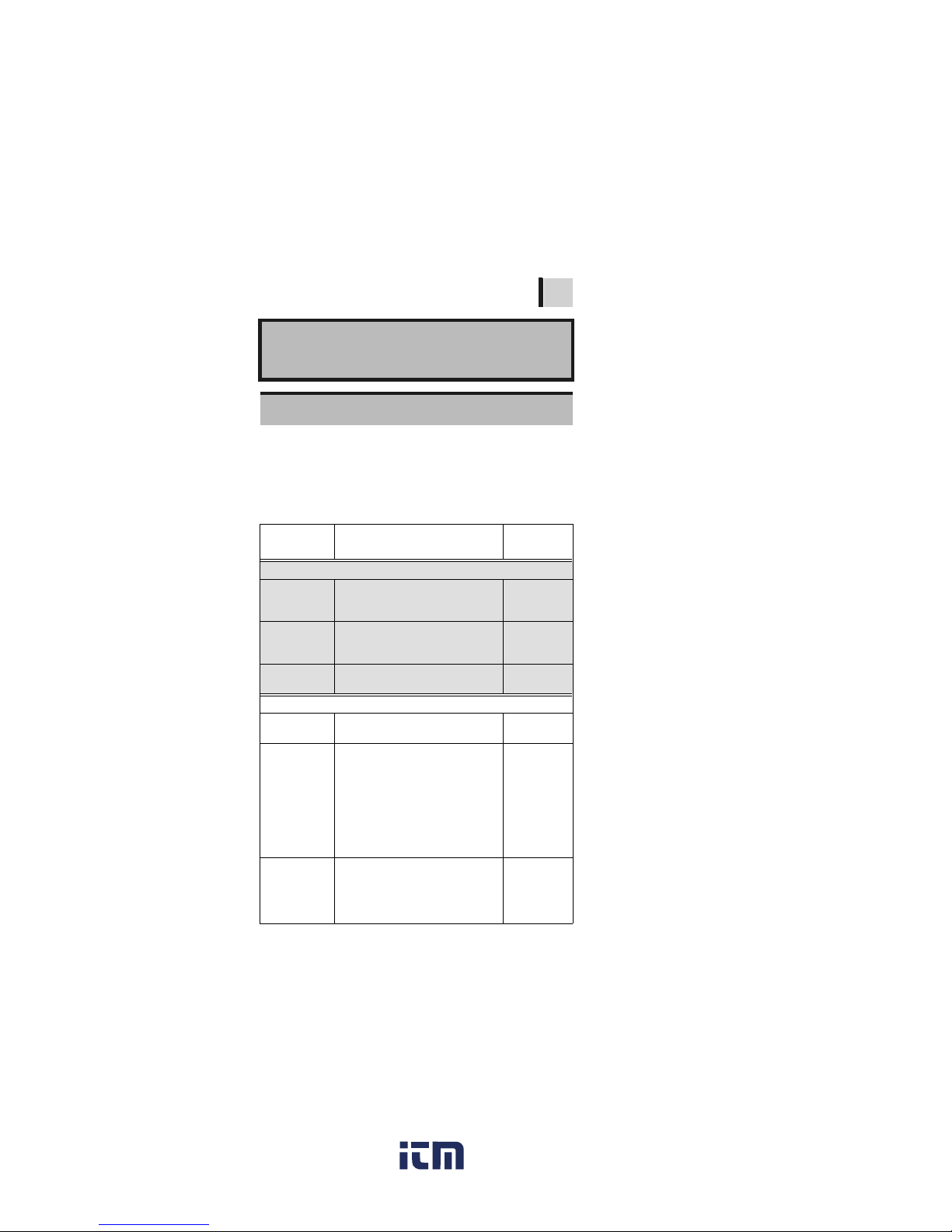
13
The 3455 is an insulation resistance tester
with a wide measurement range, for use in
such environments involving low to high
voltage.
The tester has the functions and purposes
given below.
Overview 1
1.1 Product Overview
Function Purpose
Reference
page
(Basic)
Insulation
resistance
measurement
To test the insulation resistance of
an electrical facility.
❖3.2 (P.56)
Voltage
measurement
To measure the voltage of an external circuit, e.g., commercial power
supply.
❖3.3 (P.73)
Temperature
measurement
To measure a temperature ❖3.4 (P.76)
(Applied)
Timer To automatically end measurement
after a predetermined time.
❖4.1 (P.79)
Display
PI and DAR
values
To check whether the insulation resistance increases with time after a
voltage is applied.
[When the PI (polarization index)
value or the DAR (dielectric absorption ratio) value is close to 1, the
tester determines that the insulation of the object to be measured
has deteriorated.]
❖4.2 (P.83)
Temperature
correction
(TC)
To obtain the insulation resistance
at various temperatures varied from
the actual environmental temperature at which measurement is performed.
❖4.3 (P.87)
www. .com
information@itm.com1.800.561.8187
Page 19

1.1 Product Overview
14
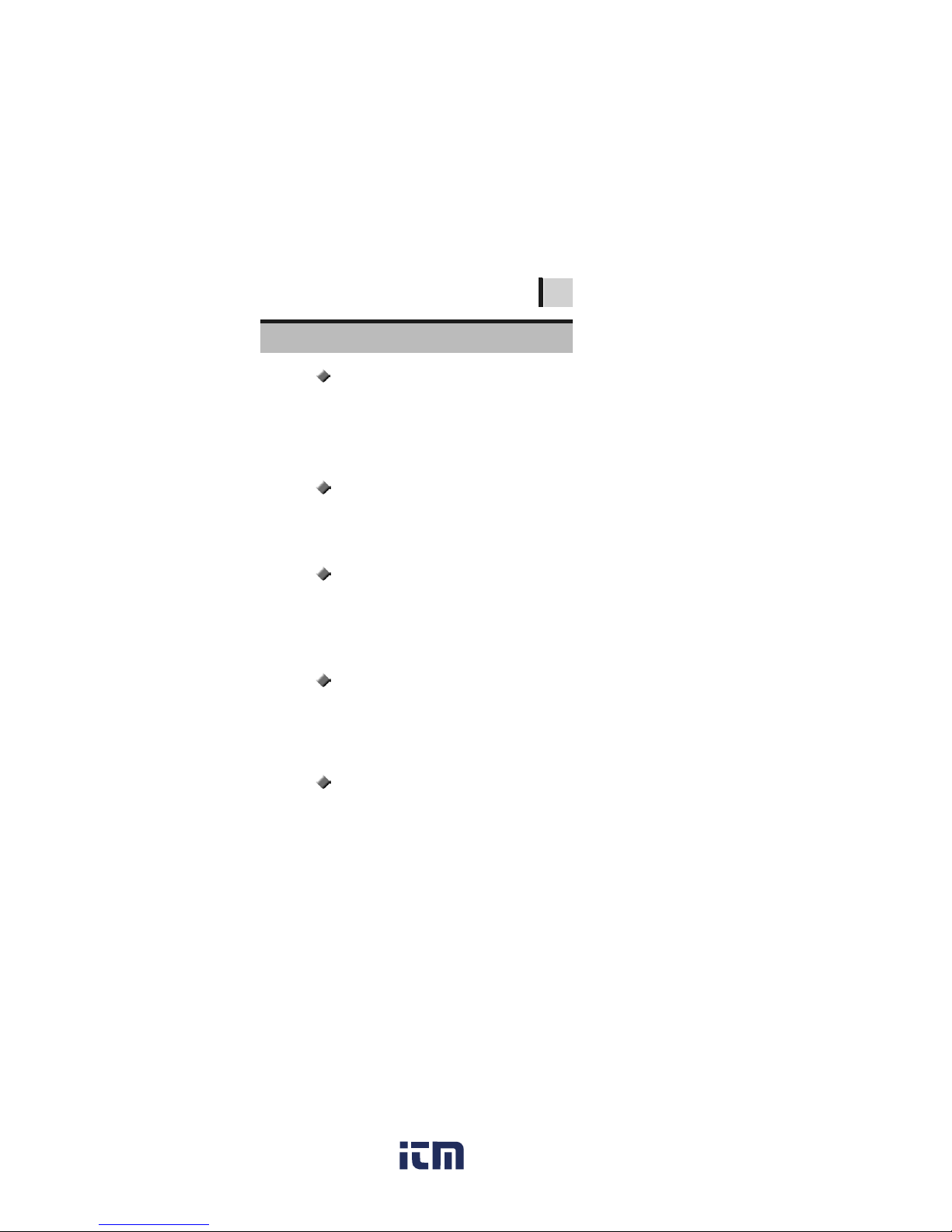
Step voltage
test
To determine whether the insulation resistance of an object changes according to test voltage
applied.
❖4.4 (P.93)
Memory
To save the measurement data.
❖5 (P.101)
PC
Communication
To create tables or graphs of the
data saved in the memory for reports, etc.
❖6.4 (P. 134)
Function Purpose
Reference
page
www. .com
information@itm.com1.800.561.8187
Page 20
1.2 Features
1
2
3
4
5
6
7
8
9
10
11
付録
索引
15
Generates a wide range of test voltages, from
250 V to 5 kV
The voltage may be chosen from the commonly used presets of 250 V, 500 V, 1 kV, 2.5
kV, and 5 kV; or set to a desired level by
increments or decrements of 25 V or 100 V.
❖3.2 "Measuring Insulation Resistance" (page 56)
For automatic ca lculation and indic ation of
PI (polarization index) and DAR (dielectric
absorption ratio), step voltage testing, and
temperature correction.
❖4 "Advanced Measurement" (page 79)
Stores up to 100 manual records and 10
logging records. The stored data may be
displayed on the LCD or downloaded to a
PC.
❖5 "Recording Measurement Data (Memory Func-
tion)" (page 101)
6.4 "Communicating with PC" (page 134)
The large display provides easy viewing.
Measurements may also be displayed
using a logari thmic bar graph, offeri ng the
feel of an analog meter.
The LCD is backlit, enabling measurement
in poor lighting condi t i on s .
The tester has a USB interface. Data stored
in the memory may be downloaded to PC
using the data download softwar e.
The same softw are also en ables re ports to
be created and printed with ease.
❖6.4 "Communicating with PC" (page 134)
1.2 Features
Wide test voltage range
Insulation diagnoses
Large memory
Large, clear display
PC software with report creation/
printing feature
www. .com
information@itm.com1.800.561.8187
Page 21

1.2 Features
16
The case is durable-designed to withstand
the toughest of working conditions, compact, and highly portable.
The tester may be powered by either alkaline or rechargeabl e ni ckel -hydro gen ba tter ies. (Selectable via switch)
❖2.1.1 "Installing or Replacing the Battery" (page
31)
2.1.2 "Installing the Battery Pack (Rechargeable
nickel-hydrogen battery)" (page 34)
Compact hard case
Dual battery power supply
www. .com
information@itm.com1.800.561.8187
Page 22

1.3 Measurement Overview
1
2
3
4
5
6
7
8
9
10
11
付録
索引
17
This tester is designed for measurement of
the following:
Measurement condition
When measuring insulation resistance,
ensure that power supply to the object
under test is turned off.
Performing Measurement
• 3455 HIGH VOLTAGE INSULATION HiTESTER
• LR6 alkaline battery, or
9459 BATTERY PACK
• 9750-01,-02,-03 TEST LEAD
• 9751-01,-02,-03 ALLIGATOR CLIP
• 9631-01,-05 TEMPERATURE SENSOR
(for temperature measurement)
1.3 Measurement Overview
Purpose : Inspection of high-voltage electrical
facilities
Location : High-voltage receiving station or trans-
forming station
Test object : Large motors, transformers, cables,
etc.
• Measures insulation resistance, voltage and temperature.
• Stores measurement data in the internal memory.
• Downloads data to a PC for table, graph, or report
creation.
www. .com
information@itm.com1.800.561.8187
Page 23
1.3 Measurement Overview
18
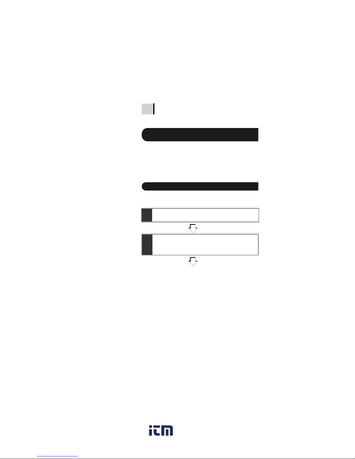
Flow of measurement
Before startin g mea surem ent, che ck th e f ollowing:
• The power supply method.
• The power ON/OFF method.
• That date and time are set.
• Connection of test leads, temperature
sensor, and USB cable .
Insulation Resistance Measurement
→3.2 "Measuring Insulation Resistance" (page 56)
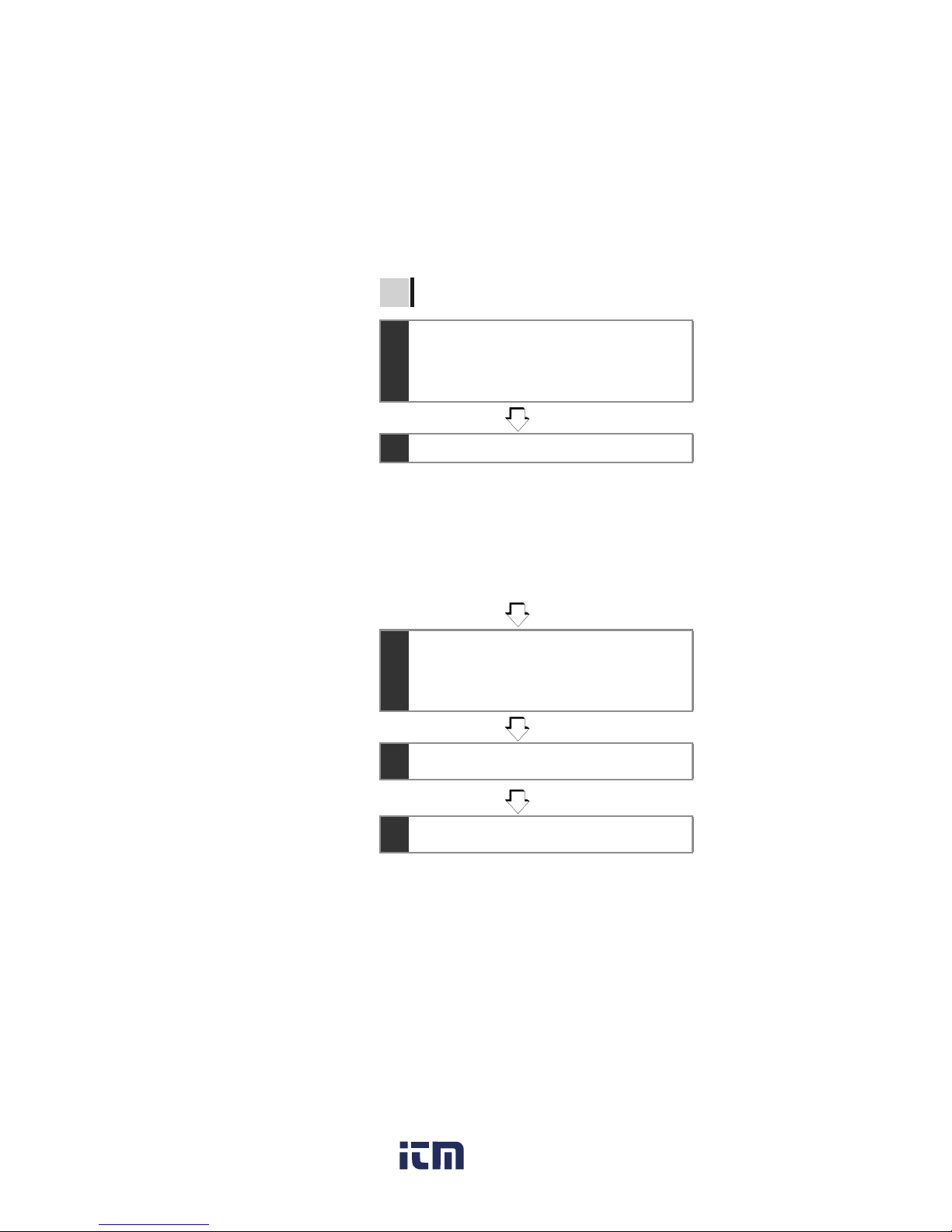
1 Prepare for measurement
→2 "Measurement Preparations" (page 31)
2 Start measurement.
1.
Make sure that powe r supply to the object under
test is turned off.
2.
Press the key to turn on
the tester.
❖2.2 (page 44)
www. .com
information@itm.com1.800.561.8187
Page 24
1.3 Measurement Overview
1
2
3
4
5
6
7
8
9
10
11
付録
索引
19
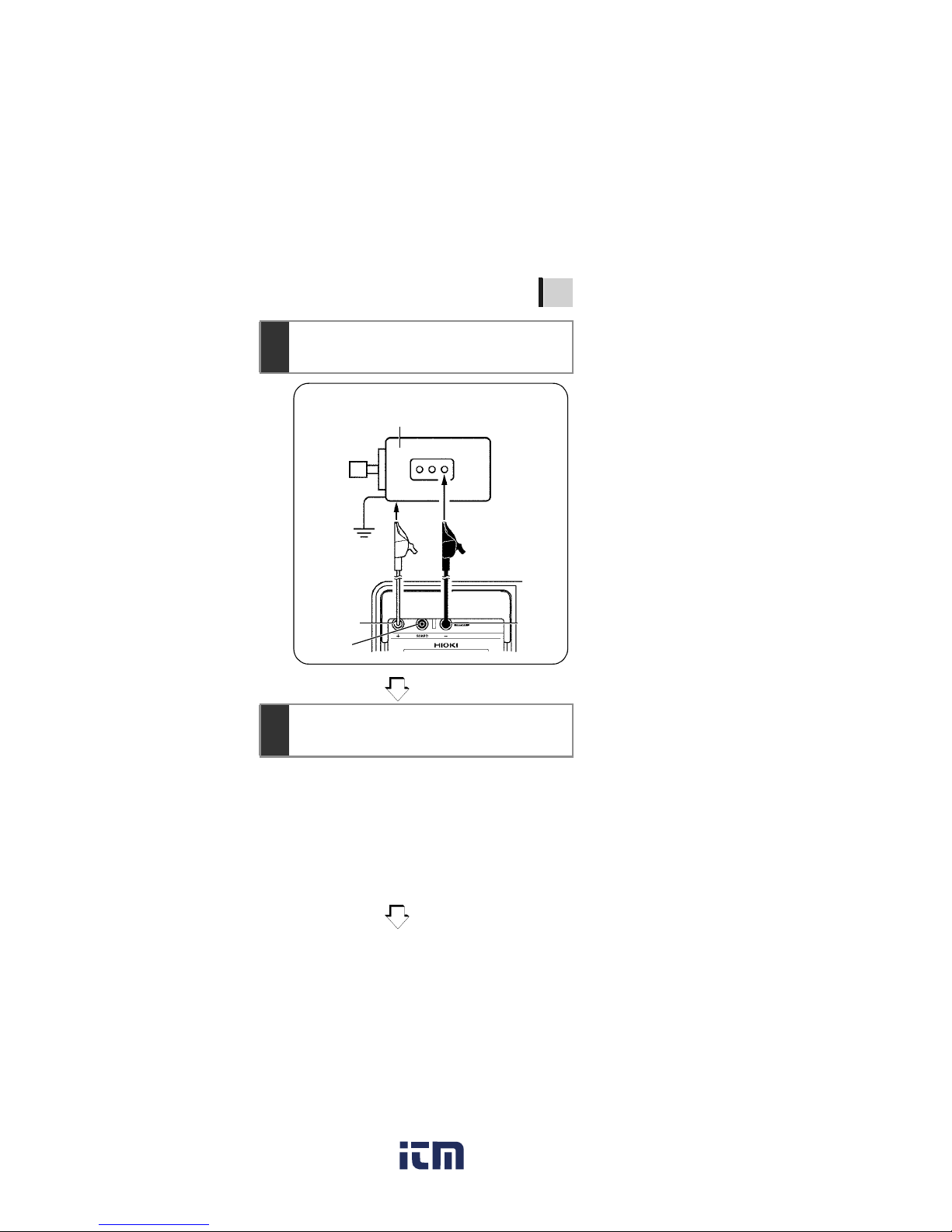
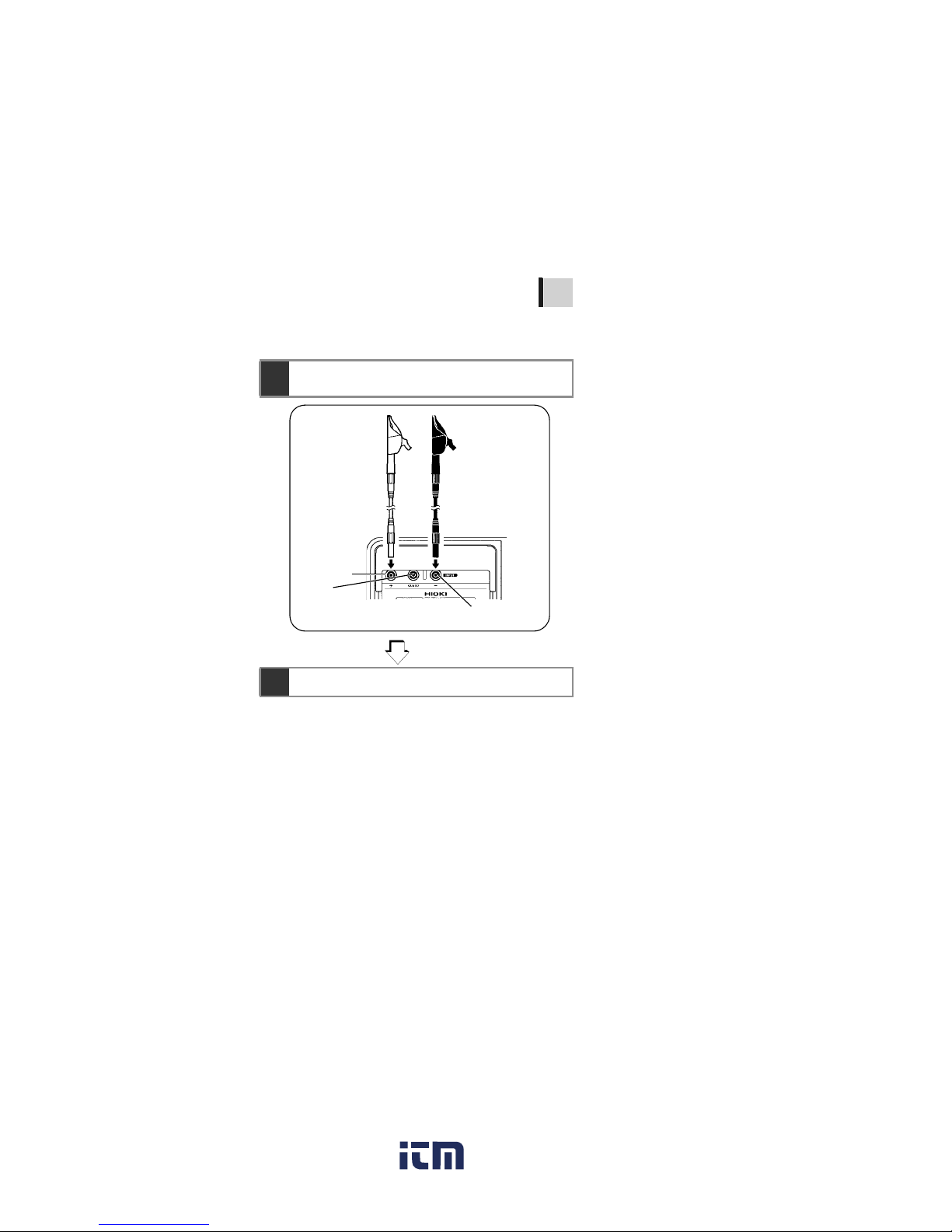
3.
Connect the test leads into the
"+" and "-" terminals of the tester
and to the object to be tested.
❖2.4 (page 50)
3.2.1 (page 58)
4.
Press the key and set
the test voltage.
❖3.2.1 (page 58)
GUARD
terminal
Warning: Confirm that the power supply to the
object under test has been turned off.
Object to be measured (Ex.: Motor)
+ terminal
- termina
l
Test lead (Red)
Attach to a metal
chassis or a ground
terminal.
Test lead (Black)
Attach to a metal part
of the power supply
terminal.
www. .com
information@itm.com1.800.561.8187
Page 25
1.3 Measurement Overview
20
5.
Press the key to generate a voltage and start measure-
ment.
❖3.2.1 (page 58)
6.
Read the indication.
❖3.2.1 (page 58)
7.
Press the key to stop
voltage generation and measure-
ment.
❖3.2.2 (page 64)
8.
The automatic discharge func tion
is activated.
❖3.2.4 (page 67)
9.
Measurement is terminated when
the voltage falls below 10 V.
www. .com
information@itm.com1.800.561.8187
Page 26
1.3 Measurement Overview
1
2
3
4
5
6
7
8
9
10
11
付録
索引
21
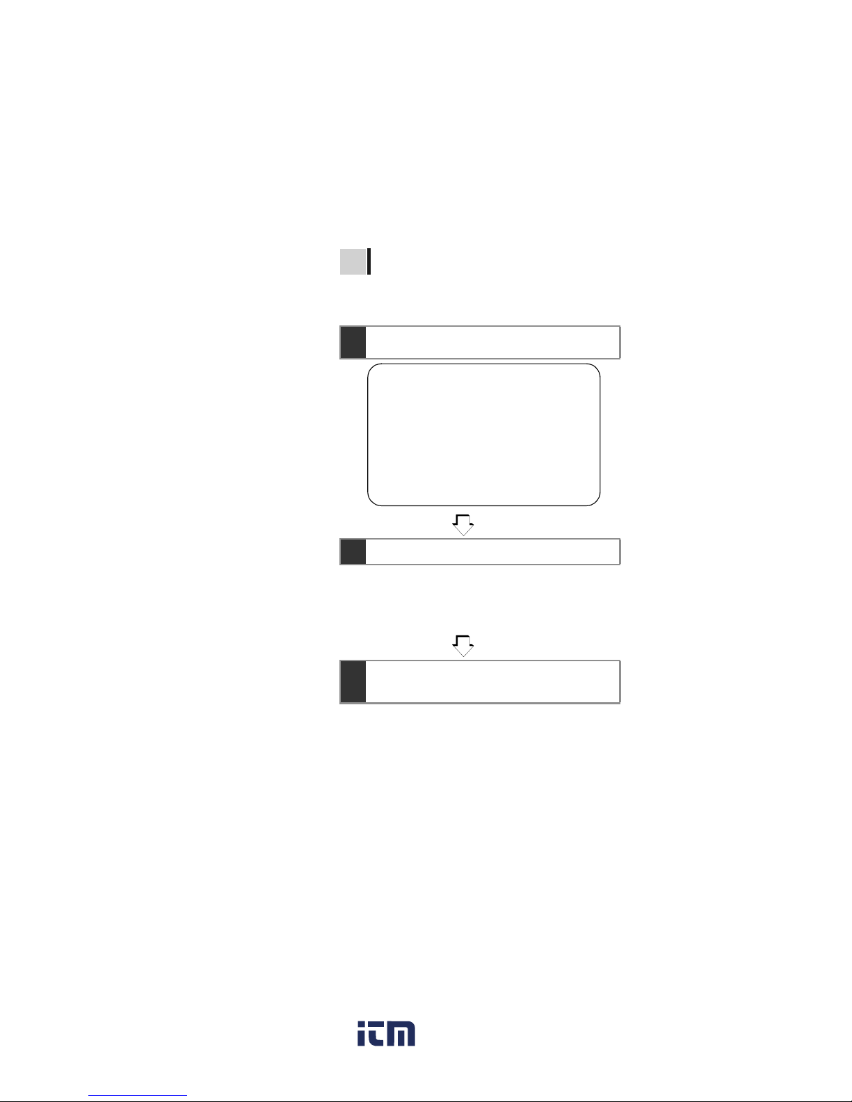
Voltage Measurement
→ 3.3 "Measuring Voltage" (page 73)
1.
Connect the test leads into the "+" and "-" terminals of the tester and to the object to be tested.
2.
Read the indication.
+ terminal
- terminal
GUARD
terminal
Test lead (Red) Test lead (Black)
www. .com
information@itm.com1.800.561.8187
Page 27
1.3 Measurement Overview
22
Temperature Measurement
→ 3.4 "Measuring Temperature" (page 76)
1.
Insert the temperature sensor into the temperature sensor terminal of the tester.
2.
Read the indication.
3.
Press the key to stop temperature measurement.
www. .com
information@itm.com1.800.561.8187
Page 28

1.3 Measurement Overview
1
2
3
4
5
6
7
8
9
10
11
付録
索引
23
Insulation resistance and temperat ure measurement data are held after measu rement
is completed.
This data will be cleared if power is turned
off. To store the data, use the memory function.
3 Record measurement data
→5 "Recording Measurement Data (Memory Function)
"
www. .com
information@itm.com1.800.561.8187
Page 29
1.4 Names and Functions of Parts
24
1.4 Names and Functions of Parts
Front
1. 2.
3.
LCD
Slide the shutter.
Operating panel
❖(page 26)
4.
567
www. .com
information@itm.com1.800.561.8187
Page 30

1.4 Names and Functions of Parts
1
2
3
4
5
6
7
8
9
10
11
付録
索引
25
Name Function
1
AC adapter
terminal
Connect the AC adapter to this terminal.
❖2.1.3 "Connecting the AC Adapter" (page
39)
2 USB terminal
Connect the USB Cable to this terminal.
❖6.4.3 "Downloading Data to Save to PC/
Setting up Tester on PC" (page 145)
3
Temperature
sensor
terminal
Connect the temperature sensor to this terminal.
❖2.5 "Connecting Temperature Sensor"
(page 52)
4 Shutter
Prevents connection to other terminals when
test leads are connected to the measurement
terminals-a safety feature.
5
+measurement
terminal
*
Connect the red test lead to this terminal.
❖2.4 "Connecting Test Lead" (page 50)
6
-measurement
terminal
*
Connect the black test lead to this terminal.
❖2.4 "Connecting Test Lead" (page 50)
7
GUARD
terminal
Connect the blue test lead to this terminal.
❖3.2.7 "Use of GUARD Terminal" (page 71)
*These are referred to simply as + and - terminals.
Back
Battery cover
Set screw
Battery pack compartment
(Under the battery cover)
Battery selector switch
(Under the battery cover)
Selects the type of battery.
LR6 alkaline battery
compartment
(Under the battery cover)
www. .com
information@itm.com1.800.561.8187
Page 31

1.4 Names and Functions of Parts
26
Key Function
1 Used to turn power on/off.
2
Used to set parameters.
Used to toggle between set voltage and monitor
voltage after resistance measurement.
3
Used to set parameters.
Used to set test voltage.
4
• Used to make fine adjustments to test voltage.
• Used to move the cursor to change units, values, etc.
• Used to display the date and time.
• Used to set the date and time.
5
• Used to make fine adjustments to test voltage.
• Used to move the cursor to change units, values, etc.
• Used to display the timer.
• Used to set the timer.
6
• Used to confirm entries.
• Used to stop temperature measurement.
Operating panel
6. 7.
2.
1.
8. 9. 10.
13.
14.
15.
11.12.
5.3.4.
www. .com
information@itm.com1.800.561.8187
Page 32

1.4 Names and Functions of Parts
1
2
3
4
5
6
7
8
9
10
11
付録
索引
27
7
(Warning lamp)
• Used to start and stop of resistance measurement.
• Blinks when a voltage is generated.
• Blinks when a voltage of 50 V or more is input
or when discharging is performed.
8
• Turns the LCD backlight on/off.
• LCD backlight automatically extinguishes after
30 seconds.
9
• Changes measurement units on the LCD.
•
When measuring resistance:
This key toggles between display of current
and resistance on the LCD
•
When the resistance value is held:
This key changes LCD display in the following
sequence: resistance→ current → DAR 1 min/
15s → DAR 1 min/30s → PI → resistance →
current → ...
10
• Used to view held temperature data.
• Used to enter the temperature of an external
thermometer.
11
Used to reduce drift of resistance or current
reading.
12 Used to enter the temperature correction mode.
13
• Used to store data in the memory.
• Used to display the date and time data was
stored in the memory.
14 Used to delete data in the memory.
15 Used to display data in the memory.
Key Function
www. .com
information@itm.com1.800.561.8187
Page 33

1.5 Screen Setup
28
❖3.3 "Measuring Voltage" (page 73)
❖3.4 "Measuring Temperature" (page 76)
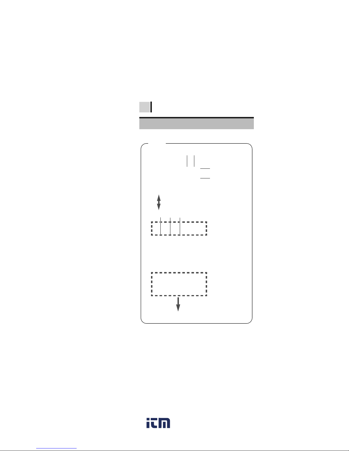
1.5 Screen Setup
All On
Measuring Voltage
Measured
voltage
Blinking
Measuring Temperature
www. .com
information@itm.com1.800.561.8187
Page 34

1.5 Screen Setup
1
2
3
4
5
6
7
8
9
10
11
付録
索引
29
❖3.2 "Measuring Insulation Resistance" (page 56)
❖3.2.5 "Switching to Leakage Current Indication"
(page 68)
Measuring Insulation Resistance
Actual outp ut
voltage
Blinking
> blinks if the
input exceeds
the measurement range.
Elapsed time Insulation resistance
The screen is switched over with th
e
key.
Leakage Current Display
Blinking
Elapsed time
Actual ou tput
voltage
The bar graph
shows the
resistance
measurement.
< blinks at
below 1 nA.
Current measurement
www. .com
information@itm.com1.800.561.8187
Page 35

2.1 Supplying Power
1
2
3
4
5
6
7
8
9
10
11
付録
索引
31
This tester may be powered by several
means.
• LR6 alkaline battery
❖See 2.1.1 "Installing or Replacing the Battery"
(page 31).
• 9459 BATTERY PACK (Option )
❖See 2.1.2 "Installing the Battery Pack
(Rechargeable nickel-hydrogen battery)" (page
34), and 2.1.4 "Charging the Battery Pack" (page
41)
• 9753 AC ADAPTER (Option)
❖See 2.1.3 "Connecting the AC Adapter" (page
39).
2.1.1 Installing or Replacing the Battery
Measurement
Preparations
2
2.1 S upplying Power
• To avoid electric shock, turn off the
power switch and disconnect the test
leads before repl ac i n g th e batteries.
• Do not mix old and new batteries, or dif ferent types of batteries. Also, be careful to observe battery polarity during
installation. Otherwise, poor performance or damage from ba ttery leakage
could result.
• After replacing the batteries, replace the
battery cover an d screws before using
the instrument.
• To avoid the possibility of explosion, do
not short circuit, disassemble or incinerate batteries .
• Handle and dispose of batteries in
accordance with local regulations.
www. .com
information@itm.com1.800.561.8187
Page 36

2.1 Supplying Power
32
Procedure
1. Turn off power and disconnect all the
test leads from the tester.
❖See 2.2 "Turning Power On and Off" (page 44).
2. Loosen the set screw on the re ar of the
tester and remove the battery cover.
• When the battery status indicator
is low, replace the batteries.
• Use the specified batteries on ly. Do not use
manganese batteries, for example, since
operating time will be greatly reduced.
• To avoid corrosion from battery leakage,
remove the batteries from the instrument
if it is to be stored for a long time.
Set screw
Remove
Battery cover
www. .com
information@itm.com1.800.561.8187
Page 37

2.1 Supplying Power
1
2
3
4
5
6
7
8
9
10
11
付録
索引
33
3. Place six LR6 alkali ne batteries into the
battery compartment. (Replace a ll six at
the same time)
4. Turn the battery selector switch to LR6.
When the power i s t u rned on, “Lr6” appears
on the top left of the screen.
❖See 2.2 "Turning Power On and Off" (page 44).
5. Replace the battery cover and tighten
the set screw.
To LR6
www. .com
information@itm.com1.800.561.8187
Page 38

2.1 Supplying Power
34
2.1.2 Installing the Battery Pack
(Rechargeable nickel-hydrogen
battery)
• Use the optional 945 9 BATTERY PACK.
The operating t ime i s lon ger t han t hat with
alkaline batteries, and the pack is
rechargeable.
• Battery pack is dispatched in an uncharged
state. Charge before use.
❖Charging Procedure→
See 2.1.4 "Charging the Battery Pack" (page
41).
• For battery operation, use only the
HIOKI Model 9459 BATTERY PACK. We
cannot accept responsibility for accidents or damage related to the use of
any other batteries.
• To avoid heat buildup, rupture, or leakage of the battery, do not use if damaged, wires are expos ed, or the batter y/
tester connector is dam aged.
• To avoid electric shock, be sure to disconnect the test leads from the tester,
turn off power, and disconnect the AC
adapter from the tester, before installing
or removing the batter y pack.
• To avoid the possibility of explosion, do
not short circuit, disassemb le or incinerate battery pack. Hand le and dispose
of batteries in accordance with local
regulations.
Take care not to step on the battery pack
power cable, as this may dam age it.
www. .com
information@itm.com1.800.561.8187
Page 39

2.1 Supplying Power
1
2
3
4
5
6
7
8
9
10
11
付録
索引
35
Installation
Procedure
Tools: Phillips screwdriver
1.
Turn off power and disconnect the test leads,
AC adapter and USB Cable from the tester.
❖See 2.2 "Turning Power On and Off" (page 44).
2. Loosen the set screw on the rea r of the
tester and remove the battery cover.
• If the battery pack is not used for an
extended period of time, remove it from the
tester and store at a temperature between
-20 to 30°C, to prevent deterioration.
• Charge the battery at least every 2
months. If the batte ry pack is lef t fo r a lo ng
period of time in a low state of charge, its
performance will be degraded.
• When the battery status indicator is low,
charge the battery pack.
• The charge stored in the battery pack
naturally dissipates over time, therefore be
sure to charge the battery pack before use.
If the operating time is extremely short
directly after the battery pack has been
charged, the battery needs to be replaced.
• The life of the battery pack is 500
charging cycles, i.e., about one year.
Set screw
Remove
Battery cover
www. .com
information@itm.com1.800.561.8187
Page 40

2.1 Supplying Power
36
3. Connect the battery pack to the tester.
(Align the protrusions.)
4. Place the battery pack in the battery
pack compartment.
5. Turn the battery selector switch to 9459.
When the power is turned on, “bP” appears
on the top left of the screen.
See 2.2 "Turning Power On and Off" (page 44).
6. Replace the battery cover and tighten the
set screw.
(Be careful not to catch the battery pack
cable in the battery cover, to prevent
damaged wiring.).
To 9459
www. .com
information@itm.com1.800.561.8187
Page 41
2.1 Supplying Power
1
2
3
4
5
6
7
8
9
10
11
付録
索引
37
Replacement
Procedure
Tools: Phillips screwdriver
1. Turn off power and disconnect the test
leads, AC adapter, and USB cable from
the tester.
❖See 2.2 "Turning Power On and Off" (page 44).
2. Loosen the set screw on the rea r of the
tester and remove the battery cover.
3. Disconnect the plu g of the battery pack
from the connector of the tester.
Set screw
Remove
Battery cover
www. .com
information@itm.com1.800.561.8187
Page 42

2.1 Supplying Power
38
4.
Connect the new battery pack to the tester.
(Align the protrusions.)
5. Place the battery pack in the battery
pack compartment.
6. Turn the battery selector switch to 9459.
When the power is turned on, “bP” appears
on the top left of the screen.
See 2.2 "Turning Power On and Off" (page 44).
7. Place the battery c over and tighten the
screw.
To 9459
www. .com
information@itm.com1.800.561.8187
Page 43

2.1 Supplying Power
1
2
3
4
5
6
7
8
9
10
11
付録
索引
39
2.1.3 Connecting the AC Adapter
• Optional 9753 AC ADAPTER can be used.
• When the AC adapter is connected to the
tester, you can ch arge the battery pack ,
communicate with a PC, perform temperature measurement, and edit the settings.
However, you cannot measure insulation
resistance, leakage current or voltage.
• Turn the instrument off before c onnecting the AC adapter to the instrument
and to AC power.
• Use only the specified Model 9753 AC
ADAPTER. AC adapter input voltage
range is 100 to 240 VAC (with ±10% stability) at 50/60 Hz. To avoid electrical
hazards and damage to the instrument,
do not apply voltage outside of this
range.
• To avoid electrical accidents and to
maintain the safety specifications of
this instrument, connect the power cord
only to a 3-contact (two-conductor +
ground) outlet.
The AC adapter cannot be used when
performing measurement using tester
leads.
www. .com
information@itm.com1.800.561.8187
Page 44

2.1 Supplying Power
40
Procedure
1. Insert the power cord into the AC
adapter.
2. Move the shutter of the tes ter to reveal
the AC adapter terminal.
3. Insert the output cable of the AC adapter
into the AC adapter terminal.
4. Make sure that the commercial power
source voltage matches the rated supply
voltage of the AC adapter. Insert the
plug into the AC outlet.
1
2 Move the shutter.
3
4
When the AC adapter is connected to the tester, power
is supplied from the AC adapter.
When both the battery and the AC adapter are connected to the tester, the battery is not used.
If the battery pack is installed, w hen the AC adapter is
connected to the tester, power of the tes ter is automatically turned on and charging of the battery pack begins.
www. .com
information@itm.com1.800.561.8187
Page 45

2.1 Supplying Power
1
2
3
4
5
6
7
8
9
10
11
付録
索引
41
2.1.4
Charging the Battery Pack
The 9459 BATTERY PACK can be char ge d
while installed in the tester, using the
optional 9753 AC ADAPTER.
Short charge time: Approx. 3 hours (at
23°C room tem perature)
Procedure
1. Install the battery pack.
❖See 2.1.2 "Installing the Battery Pack
(Rechargeable nickel-hydrogen battery)" (page
34).
• Carry out battery charging at an ambient
temperature between 10°C and 40°C.
However, the ambient temperature may
influence the charging efficiency. Outside
this range, not onl y is the c harging c apacity
reduced, but also there is a possibility of
reduced performa nce o r electrolyte leak age.
• The battery pack cannot be charge d when
test leads are connected to the tester.
• The battery pack will be charged regard le ss
of the battery selector switch position.
• Communication with a PC and temp erature
measurement are available during charging.
But, insulation resistance measurement and
voltage measurement are not available.
• Only use the specified battery charger.
• Do not recharge a fully-charged battery
pack. If the ba ttery pack is o ver-charg ed,
a deterioratio n in performance or ba ttery
fluid leakage may result.
www. .com
information@itm.com1.800.561.8187
Page 46

2.1 Supplying Power
42
2. Move the shutter to reveal the AC
adapter terminal.
3. Connect the AC adapter to the AC
adapter terminal.
Rapid charging begins. During rapid charging, the battery status indicator blinks.
❖See 2.1.3 "Connecting the AC Adapter" (page
39).
Move the shutter.
1
2
3
Battery status indicator
Charging
If the AD adapter is connected to the tester when the
tester is off, the tester is automatically turned on and
rapid charging begins.
www. .com
information@itm.com1.800.561.8187
Page 47

2.1 Supplying Power
1
2
3
4
5
6
7
8
9
10
11
付録
索引
43
4. When rapid charging is completed, the
battery status indictor changes from
blinking to continuously lit. After rapid
charging finishes, the battery is tricklecharged (maintained in a fully-charged
state).
www. .com
information@itm.com1.800.561.8187
Page 48

2.2 Turning Power On and Off
44
Press and hold the key for
around one second.
After all the screen indications light, the
version and the position of the battery
selector switch appear and then the
tester enters the standby state.
The tester recalls the settings that were
present before power was last turned off.
Press the key.
The screen is switched off and power is
turned off.
2.2 Turning Power On and Off
T urning power On
Indicates the position of the battery selector switc
h.
bP: Using the Model 9459 BATTERY PACK
Lr6: Using the LR6 alkaline batteries
Version
When the battery status indicator
is low, replace the battery.
❖See 2.1.1 "Installing or Replacing the Battery"
(page 31).
If the batteries or the battery pac k i s ru nning
low, [
LObAt] is indicated. The tester turns
off if use is continued.
T uring power off
www. .com
information@itm.com1.800.561.8187
Page 49

2.2 Turning Power On and Off
1
2
3
4
5
6
7
8
9
10
11
付録
索引
45
2.2.1 Auto Power Off
• Power is automatically turned off around
10 minutes after the last operation. This
function, however, is not available during
insulation resistance measurement.
•[
APS] will start blinking around 30 sec-
onds before power is turned off .
• Auto power off is re-enabled upon turning
power on again . ([
APS] lights up.)
• When the AC adapter is connected to the
tester, auto power off is disabled.
• When the timer is set or when the tester is
in the step voltage test mode, auto power
off is disabled.
Turn on power while holding down the
key.
Canceling Auto Power Off
www. .com
information@itm.com1.800.561.8187
Page 50

2.3 Setting and Checking Date and Time
46
Set the time and date before use of the
tester. Use the Christian calendar.
2.3.1 Setting Date and Time
Procedure
1.
When the tester is in a standby state, press
the key. Year, month, and day appear .
2. Hold down key for more than one
second. The Year starts blinking.
2.3 Setting and Checking Date
and Time
www. .com
information@itm.com1.800.561.8187
Page 51

2.3 Setting and Checking Date and Time
1
2
3
4
5
6
7
8
9
10
11
付録
索引
47
3. Pressing moves the blinking
cursor. Place the cursor at the digit,
value, etc., you wish to change.
Year, month, day, hour, and minutes can
be changed.
The year-month-day screen and the hourminute-second screen are switched to and
from each other in the procedur e bel ow.
4. Press to change the number.
Hold down for fast increase/decrease.
5. The entry is confirmed by pressing the
key, after which the display returns
to the standby screen.
The clock starts to run from zero seconds
as soon as key is pressed.
Year-month-day
↓
Hour-minute-
second
• When year [
YEAR] is blink-
ing, press the key.
• When day [
DAY] is blinking,
press the key.
Hour-minute-
second
↓
Year-month-day
• When hour [
h] is blinking,
press the key.
• When minute [
min] is blink-
ing, press the key.
www. .com
information@itm.com1.800.561.8187
Page 52

2.3 Setting and Checking Date and Time
48
• The date and time can be set on a PC
using the data analysis software for
model 3455.
• The data analysis software for model
3455 must be installed on the PC.
❖Details → See 6.4 "Communicating with PC"
(page 134).
Date and time can be set on a PC.
www. .com
information@itm.com1.800.561.8187
Page 53

2.3 Setting and Checking Date and Time
1
2
3
4
5
6
7
8
9
10
11
付録
索引
49
2.3.2 Checking Date and Time
Procedure
1. When the tester is in the standby state,
press the key.
Year, mon th , an d da y app ea r.
2. Press the key.
Hours, minutes, and seconds appear.
3. Pressing key returns to the standby
screen.
www. .com
information@itm.com1.800.561.8187
Page 54

2.4 Connecting Test Lead
50
Procedure
1. Connect the alligat or clip to the end of
each test lead. Insert it fully.
2. Move the shutter to re veal the + and -
terminals.
2.4 Connecting Test Lead
• To avoid electric shock, be sure to disconnect the test leads from the object
under test and turn off power, before
connecting or disconnecting the test
leads to/from the tester.
• To avoid electric shock, never use the
tester if the shutter is broken.
Test leads cannot be connected to the
tester if the AC adapter, a temperature
sensor, or USB Cable i s connected.
www. .com
information@itm.com1.800.561.8187
Page 55

2.4 Connecting Test Lead
1
2
3
4
5
6
7
8
9
10
11
付録
索引
51
3. Connect the red test lead to the + terminal
and the black test lead t o the - t ermi nal.
For insulation resistance m easurement,
connect the blue test lead to the GUARD
terminal if necessary.
Check that the test leads are fully
inserted.
❖GUARD terminal → See 3.2.7 "Use of GUARD
Terminal" (page 71).
+ terminal
- termina
l
GUARD
terminal
Test lead (Red) Test lead (Black)
www. .com
information@itm.com1.800.561.8187
Page 56

2.5 Connecting Temperature Sensor
52
Procedure
1. Move the shutter to reveal th e temperat ure
sensor terminal.
2. Connect the tempe rature sensor to the
temperature sensor terminal.
Temperature measurement begins automatically.
2.5 Connecting Temperature
Sensor
Temperature sensors may be damaged by
high voltage or static electricity. Do not
expose the temperature sensor to excessive
impact, or allow the cable to be bent, since
malfunction or faulty connection may result.
Temperature sensors cannot be used
simultaneously with test leads.
Move the shutter.
Temperature
sensor terminal
www. .com
information@itm.com1.800.561.8187
Page 57

3.1 Pre-Operation Inspection
1
2
3
4
5
6
7
8
9
10
11
付録
索引
53
To ensure safe use of the tester, be
sure to check it before use.
Confirm that the tester chassis, shutter, test
leads, and clips are not damaged.
Do not used if damaged.
Equipment
•20 MΩ resistor that provides a voltage of
5 kV
• High-voltage meter with an input resistance of 1,000 MΩ or more, and capable
of measuring up to 5.5 kV DC
Measurement 3
3.1 Pre-Operation Inspection
Before using the inst rument, make sure
that the insulation on the test leads and
cables is undamaged and that no bare
conductors are improperly exposed.
Using the product in such conditions
could cause an electric shock, so contact
your dealer or Hioki representative for
replacements.
Make sure the terminals are clean and dry.
Wipe with a dry cloth to remove any
moisture, since measurement errors may
result if moisture is present.
❖See 8.2 "Cleaning" (page 162).
Checking for damage
Checking test voltage and resistance
reading
www. .com
information@itm.com1.800.561.8187
Page 58

3.1 Pre-Operation Inspection
54
Inspection
Procedure
1. Clip the resistor to the red and black test
leads connected to the tester.
2. Also, clip the resisto r to the test lead of
the high-voltage meter.
3. Set the test voltage of the tester to
[5.00 kV].
❖See 3.2Measuring Insulation Resistance, Proce-
dure 5. (page 60) to 8. (page 60).
4. Hold down key for more than
one second to start insulation re sistance
measurement.
5.
Check to see if the reading of the high-voltage meter is somewhere between 5 kV and
5.5 kV.
6. Check to see if the voltage reading of the
tester is somewhere betwee n 5 kV and
5.5 kV.
www. .com
information@itm.com1.800.561.8187
Page 59

3.1 Pre-Operation Inspection
1
2
3
4
5
6
7
8
9
10
11
付録
索引
55
7. Check to see if the insulation resistance
reading of the tester is 20 MΩ.
8. Stop insulation resistance measurement.
❖See 3.2.2 "Ending Measurement" (page 64).
9. Short-circuit the tips of the clips of the
red and black test leads of the tester.
10. Press the key to see if the test volt-
age setting is [5.00 kV].
11. Hold down the key for more than
one second to start insulation resistance
measurement.
12. Check to see if the insulation resistance
reading of the tester is 0.00 MΩ.
If a problem exists, discontinue use of
the tester.
Insulation resistance
Voltage
www. .com
information@itm.com1.800.561.8187
Page 60

3.2 Measuring Insulation Resistance
56
3.2 Measuring Insulation
Resistance
Observe the following to avoid electric
shock and short circuits.
A. Do not use the
tester if the shutter
is broken.
B. Check Table 1
before connecting test leads to the tester.
C. Ch eck to see if the o bject under test i s not
live or electrically charged using a high-voltage detector or other similar instrument,
before connecting test leads to it.
Table 1
Check item Result Action
Are the mark
and key lamp
off?
Off Connect test leads to the tester
and check C. above. If safe to
proceed, connect the test leads
to the object under test.
→ Go to Table 2.
Blinking Press the key to stop
voltage generation.
Table 2
Check item Result Action
Are the mark
and key lamp
blinking?
Not blinking Measurement may be com-
menced
Blinking Immediately disconnect the
test leads from the object under test and turn off power to
the object or discharge the
electric charge using a discharge rod.
Shutter
www. .com
information@itm.com1.800.561.8187
Page 61

3.2 Measuring Insulation Resistance
1
2
3
4
5
6
7
8
9
10
11
付録
索引
57
• When measuring insulation resistance,
dangerous voltage is applied to the
measurement terminals. To avoid electric shock, do not touch the terminals
and test leads.
• Do not touch the object under test or
disconnect the test leads after measurement has been co mp l et ed u ntil the automatic discharge function is comple ted.
Electric shock may result due to high
voltage an d stored charge.
❖See 3.2.4 "Automatic Discharge Function" (page
67).
• Power of the tester may be turned off
during measure ment even if the
key is not pressed, for instance, due to
battery consumption. In such ca se, the
automatic discharge function may not
operate. Discharge the object under
test using a discharge rod for h igh volt age.
• To avoid damage to objects under test, be
sure to check the test voltage before
starting measurement.
• When repeating measurement, press the
key before next measurement to check
the test voltage.
• To avoid damage to the tester during
discharge, do not measure the insulation
resistance between the terminals of
capacitors (with a capacitance of over 4 μF).
• To avoid damage to the tester, do not
short-circuit the tips of the clips of the red
test lead (+ terminal) and the blue test lead
(GUARD terminal).
www. .com
information@itm.com1.800.561.8187
Page 62

3.2 Measuring Insulation Resistance
58
3.2.1 Starting Measurement
Procedure
1. Connect the alligat or clip to the end of
each test lead. Insert it fully.
2. Move the shutter to re veal the + and -
terminals.
www. .com
information@itm.com1.800.561.8187
Page 63

3.2 Measuring Insulation Resistance
1
2
3
4
5
6
7
8
9
10
11
付録
索引
59
3. Connect the red test lead to the + terminal
and the black test lead t o the - t ermi nal.
Connect the blue test lead to the
GUARD terminal if necessary.
Fully insert the test leads.
❖See 3.2.7 "Use of GUARD Terminal" (page 71).
4. Clip the alligator clip at the end of each
test lead to the object under test.
GUARD
terminal
Warning: Confirm that the power supply to the
object under test has been turned off.
Object to be measured (Ex.: Motor)
+ terminal
- termina
l
Test lead (Red)
Attach to a metal
chassis or a ground
terminal.
Test lead (Black)
Attach to a metal part
of the power supply
terminal.
www. .com
information@itm.com1.800.561.8187
Page 64

3.2 Measuring Insulation Resistance
60
5. Press the key, after which the
voltage disp l ay starts blinki ng .
6. The test voltage is chosen from 250 V,
500 V, 1.00 kV, 2.50 kV, and 5.00 kV
using the keys.
7. Pressing keys, you can make
fine adjustment of the test voltage setting.
8.
Press the key to set the test voltage.
The voltage indication will change from
blinking to continuous.
This test voltage is now set.
For step voltage testing, h old down the key,
which will display [
STEP]. For non-stepped insula -
tion resistance measurement, pre ss the key
and choose a voltage.
www. .com
information@itm.com1.800.561.8187
Page 65

3.2 Measuring Insulation Resistance
1
2
3
4
5
6
7
8
9
10
11
付録
索引
61
9. Hold down the key for more than
one second.
A voltage is generated and measurement
begins.
The mark and key lamp
starts blinkin g.
If > blinks, the input value is out of measurement range.
Example: > 5.00TΩ means "larger than 5.00 TΩ."
• During measureme nt, [
SET] is turned off in the voltage indica-
tion field and the indication ch anges from the test voltage to
the actual output voltage. A voltage approximatel y 5% higher
than the set level is output.
• To view the set voltage during measurement, press the
key. The set voltage is displayed for approximately 2 seconds.
• During measurement, i f the output voltage is lower than the
set level, the voltage indication blinks.
• Under the resistance indication appears time elapsed from the
start of measurement.
Actual outp ut
voltage
Blinking
>blinks if the
input exceeds the
measurement
range.
Elapsed time Insulation resistance
www. .com
information@itm.com1.800.561.8187
Page 66

3.2 Measuring Insulation Resistance
62
10. Read the indication.
• If the indication is unstable, press the key.
The average of the measurements is shown.
• Resistance indication is switched to leakage current
indication by pressing the key.
❖See 3.2.5 "Switching to Leakage Current Indication" (page
68).
• When the timer has been set, remaining time is displayed.
❖See 4.1 "Using Timer" (page 79).
Do not allow test leads to contact each other
or place objects on test leads, to avoid measurement errors and mal functions.
• Be sure to clean test leads after use. If test
leads are soiled, they may deteriorate.
• Insulation resistance is unstable. The
indication may not stabilize with some
objects.
• Due to factors such as capacitance of
objects under test, resistance values may
start low, then ri se gradually and set tle out.
• During measur ement, if the resis tance of
the object suddenly drops or if the test
lead tips are short-circuited, the tester
stops voltage generation as a safety
measure. (This applies to a test voltage of
1.1 kV or more.)
www. .com
information@itm.com1.800.561.8187
Page 67

3.2 Measuring Insulation Resistance
1
2
3
4
5
6
7
8
9
10
11
付録
索引
63
When the display reflects the following
state, insulation resistance measurement
cannot be started.
• The setting value is blinking to indicate
that the instrument being set up
• The mark is blinking
• While [TC] is lit, the actual measurement
temperature is shown as [- - -]
• An error massage is displayed
If the indicat ion is unstable, the averag e of
the measurement is shown.
Pressing the average key togg l es [AVE] on/
off.
While [AVE] is on, display update interval is
four seconds, normally.
But in the following case, the interval is one
second even if [AVE] is on .
• During 15 seconds after the measurement started
• During 5 to 10 seconds after the measurement range changed
The state not to be started the meas urement
Average function
www. .com
information@itm.com1.800.561.8187
Page 68

3.2 Measuring Insulation Resistance
64
3.2.2 Ending Measurement
Procedure
1. Press the key with the test leads
connected to the object unde r te st.
The last measurement is held.
( lights up.)
2. Immediately after measurement has
been completed, the discharg e circuit in
the tester automatically discharges the
electric charge remaining in the object
under test.
❖See 3.2.4 "Automatic Discharge Function" (page
67).
3. During discharge, the mark and
key lamp blinks.
The voltage indication shows the progress
of discharge.
www. .com
information@itm.com1.800.561.8187
Page 69

3.2 Measuring Insulation Resistance
1
2
3
4
5
6
7
8
9
10
11
付録
索引
65
4. When the voltage falls to about 1 0 V, the
tester stops discharging and the mark
and key lamp are turned off.
5. To restart measurement, press the
key to check the test voltage before
resuming measurement.
• If the key is press ed du ring mea surem ent,
automatic discharge is performed before power is
turned off.
• If the battery runs low during measurement, the
tester automatically stops measurement. Automatic
discharge is performed and then [LObAt] appears on
the screen.
LastElapsed time of the
Actual output
voltage
(last measurement)
end of measurement measurement value
Check
www. .com
information@itm.com1.800.561.8187
Page 70

3.2 Measuring Insulation Resistance
66
3.2.3 Checking and Deleting Held Data
The following data are held and displayed
after insulation resistance measurement
has been completed.
• Insulation resistance (digital value and
bar graph)
• Test voltage
• Actual output voltage
• Leakage current
• Elapsed time
Some data may not be di splayed. Press the
keys shown in the table below to switch the
indication.
To clear the data, press the key for more
than one second.
Temperature/humidity data will not be
cleared.
Checking Held Data
Data indications to be switched Keys used
key
key
Elapsed time ↔ Temperature/humidity
(When the data are held)
key
Insulation
resistance
Leakage
current
↓
← DAR 1 min/ 30 s
↑
PI (10/1 min.)
DAR 1 min/15 s
↓
→
Test voltage
(setting)
Actual outpu t
voltage
↔
The held data are cleared when power is
turned off. To save the data, use the
memory function.
❖See 5 "Recording Measurement Data (Memory
Function)" (page 101).
Deleting Held Data
www. .com
information@itm.com1.800.561.8187
Page 71

3.2 Measuring Insulation Resistance
1
2
3
4
5
6
7
8
9
10
11
付録
索引
67
3.2.4 Automatic Discha rge Function
• When insulation resistance with a capacitance component is measured, this component remains charged with a highvoltage equivalent to the test voltage,
which is dangerous.
• This tester automatically discharges
remaining electric charge using the internal circuit after measuremen t.
• Make sure that the test leads are connected
to the measured object when pressing the
key to stop measurement.
• Discharging stops when the residual voltage falls below 10 V. The discharge time
varies depending on the capacitance.
After the voltage has been decreased by
the tester’s automatic discharge function,
the voltage in the measurement area may
rise again due to the remaining charge in
the capacitor C
A shown in the diagram in
section 3.2.6. Take great care when touching the object under test.
www. .com
information@itm.com1.800.561.8187
Page 72

3.2 Measuring Insulation Resistance
68
3.2.5 Switching to Leakage Current Indication
Insulation resistance indication may be
switched to leakage current indication.
Every time the key is pressed, the
indication changes in the order: resistance
→ current → PI → resistance → etc.
Every time key is pressed, the indication changes in the order: resistance
→
current → resistance → current → etc.
During measurement
Blinking
Elapsed time
Actual ou tput
voltage
The bar graph
shows the
resistance
measurement.
< blinks at
below 1 nA.
Current measurement
Before me asur ing in sul ati on r esi stance
and after se tting test v olt age
( indicator is off.)
Measuring insulation resistance
www. .com
information@itm.com1.800.561.8187
Page 73

3.2 Measuring Insulation Resistance
1
2
3
4
5
6
7
8
9
10
11
付録
索引
69
Every time key is pressed, the indication changes in the order: resistance
→
current → DAR 1 m in/15s → DAR 1 min/30s
→ PI → resistance → current → etc.
❖PI/DAR → See 4.2 "Displaying PI and DAR"
(page 83).
3.2.6 Insulation Resist ance M easurement
Basis
When a high DC voltage is applied to an
object under test, a leakage current flows.
The insulation resistance tester measures
the applied voltage V and the combined
leakage current I and then calculates the
insulation resist ance R.
Calculation formula R = V/I
I
C and IA gradually decrease after the volt-
age is applied.
Holding data after measurement
If the indication is unstable, press the key. The
average of the measurements is shown.
[< 1.00 nA] means "below 1.00 nA."
Applied
voltage
V
Insulation
tester
Capacity
C
Insulation
resistance
R
Steady-state
leakage
current
I
R
Charge
current
I
C
Absorption
current
I
A
Insulating material
C
A
Combined leakage current I
A
Current
detector
R
A
www. .com
information@itm.com1.800.561.8187
Page 74

3.2 Measuring Insulation Resistance
70
When measuring the same object repeatedly, the insulation resistance and leakage
current indications may differ. This is caused
by polarization*, which occurs when a voltage is applied to an insulating material.
An insulating material is represented by an
equivalent circuit as shown by the diagram
on the previous page.
Absorption current due to relatively slow
polarization is represented by I
A, as shown
in the diagram above. It takes time for the
polarization caused by the previous measurement disappear. Until it does, electric
charge remains in C
A as shown in the dia-
gram. The electric charge level in C
A differs
at the start of previous measurement and at
the start of next measurement and thus
absorption current I
A differs, too. Further, the
combined leakage current and insulation
resistance vary from measurement to measurement. This will be become more apparent for higher insulation resistance values.
To ensure reproducibility of measurement,
leave a sufficient time interval between measurement sessions. Further, the ambient
temperature and humidity should not vary.
*Polarization: the phenomenon in which positive
negative charges on the atoms of a
material move in opposite directions
when an electric field is applied to the
material.
Reproducibility of insulation resistance
measurement
www. .com
information@itm.com1.800.561.8187
Page 75

3.2 Measuring Insulation Resistance
1
2
3
4
5
6
7
8
9
10
11
付録
索引
71
3.2.7 Use of GUARD T erminal
A GUARD terminal is used to prevent the
surface electrical resistance of an insulating
material affecting measurement, enabling
correct measurement of the entire volume of
the material.
When testing the insulation of a cable, as
shown in the diagram above, wind a bare
conductor around th e surface of the insulating material and connect the conduc tor to
the GUARD terminal. This prevents the
leakage current on the surface of the insulating material flowing into the current
detector, which enables the actual resistance of the entire vo lume of the insu lating
material to be measured.
Measurement unaffected by surface
electrical re sis t ance
Metallic shielding layer
Bare conductor
Insulating material
Cable
Core
Current
detector
Power supply
www. .com
information@itm.com1.800.561.8187
Page 76

3.2 Measuring Insulation Resistance
72
G terminal grounding is used for measuring
the insulation resistance between the core
and the metallic shielding layer of a highvoltage cable with the cable connected to
other high-voltage equipment. The diagram
below shows an example of measurement.
Rc: Insulation resistance of the insulating
material of the high-voltage cable
(Between core and metallic shielding
layer)
Rs: Insulation resistance of the sheath of
the high-voltage cable
(Between metallic shielding layer and
ground)
Rn: Insulation resistance between insulator
or high-voltage equipment and ground
Influence of Rs and Rn is removed and
solely Rc is measured.
Reference
→ High-voltage power receiving
facility code 2002
Measurement using G (GUARD)
terminal grounding
Meter transformer
Disconnecto
r
Load
Core
R
nRc
Rs
N
Remove
Grounding
P
Power supply
wire
Cable
Power
supply
side
side
wire
Metallic shielding layer
of the cable
Current
detector
www. .com
information@itm.com1.800.561.8187
Page 77

3.3 Measuring Voltage
1
2
3
4
5
6
7
8
9
10
11
付録
索引
73
The tester measures the voltage of an external circuit, e.g., commercial power supply.
AC and DC are d i stinguished automatically.
3.3 Measuring Voltage
To prevent damage to the tester and personal injury, observe the precautions
below.
• Maximum rated voltage to ground: 1,000
Vrms (CATIII), 600 Vrms (CATIV)
• Do not conduct m easurement exceeding
these voltages to ground.
• Maximum input voltage: 750 Vrms, 1,000
VDC
• Do not conduct m easurement exceeding
this maximum input voltage.
• Maximum input frequency: 70 Hz
• Do not conduct measurement exceeding this maximum input frequency.
• Do not short-circuit a line voltage
applied with the
tip of test lead.
• Do not use the
tester if the shutter
is broken.
Do not clamp two lines.
Shutter
www. .com
information@itm.com1.800.561.8187
Page 78

3.3 Measuring Voltage
74
Procedure
1. Connect alligator clips to the ends of test
leads. Insert it fully.
2.
Move the shutter to reveal the + and terminals.
3. Connect the red test lea d to the + termi-
nal and the black test lead to t he - t erminal. Fully insert the test leads.
+ terminal
- terminal
GUARD
terminal
Test lead (Red) Test lead (Black)
www. .com
information@itm.com1.800.561.8187
Page 79

3.3 Measuring Voltage
1
2
3
4
5
6
7
8
9
10
11
付録
索引
75
4. Clip the ends of the test lea ds to the cir-
cuit to be tested. When the voltage
exceeds 50 V, the mark and
key lamp blink.
5. Read the voltage indication.
The key is not used.
Measured
voltage
Blinking
www. .com
information@itm.com1.800.561.8187
Page 80

3.4 Measuring Temperature
76
3.4.1 Measurement Procedure
Procedure
1. Move the shutte r to reveal the temp era-
ture sensor terminal.
2. Connect the tempe rature sensor to the
temperature sensor terminal.
3.4 Measuring Temperature
Do not attem pt to measure th e temperature of objects carrying a voltage. Doin g
so will resu lt in a short-cir cu i t accident or
an electrocution accident.
Temperature sensors may be damaged by
high voltage or static electricity. Do not
expose the temperature sensor to excessive
impact, or allow the cable to be bent, since
malfunction or faulty connection may result.
Move the shutter.
Temperature
sensor terminal
www. .com
information@itm.com1.800.561.8187
Page 81

3.4 Measuring Temperature
1
2
3
4
5
6
7
8
9
10
11
付録
索引
77
Temperature measurement begins automatically.
3. Read the temperature indication.
4. Press key or disconnect the tem-
perature sensor to stop measureme nt.
lights up and th e last mea-
surement is held.
❖Detailing the above display→See 6.3.2 "Clearing
Indications of Temperature and Humidity Stored
Data" (page 133).
After measuring tempe rature
(When the resistance is not measured.)
www. .com
information@itm.com1.800.561.8187
Page 82

3.4 Measuring Temperature
78
• If temperature measurement is stopped using the
key, measurement may be resumed by pressing
the key.
• When an insulation resi stance measurement is held, if
the temperature sensor is disconnected, the temperature indication switches to the elapsed time indication at
the time of insulation resis tance measurement. To display the held temperature instead of the elapsed time,
press the key. (The temperature will blink.)
• Held measurement values are cleared when power is
turned off. To save the data, use the memory function.
❖See 5.1.1 "Manual Recording (Recording result of one mea-
surement session)" (page 103).
• Settings cannot be edited during temperature measure-
ment. To edit settings, stop temperature measurement.
•[OF] means exceeding 70.0°C.
[-OF] means below -10.0°C.
After measuring temperature
(Disconnecting the temperature sensor,
resistance value is held)
www. .com
information@itm.com1.800.561.8187
Page 83

4.1 Using Timer
1
2
3
4
5
6
7
8
9
10
11
付録
索引
79
If the timer is set during insulation resistance measurement, the measurement
automatically ends at the set time.
Selectable t ime: 30 sec. to 3 0 min. (When
setting over 1 minute, time increments or
decrements in minutes.)
4.1.1 Setting Timer/Conducting Insulation
Resistance Meas urement
Procedure
1. When the tester is in a standby state,
press the key.
The time indicat i on wi l l bl i nk.
2. Press the key to set the time.
Advanced
Measurement
4
4.1 Using T imer
What is it used for?
Used to set the tester to automatically stop at a specified time.
www. .com
information@itm.com1.800.561.8187
Page 84

4.1 Using Timer
80
3. Press the key to confi rm t he ent ry.
If the key is pressed without pressing
the key, the tester returns to a
standby state wit h th e ti me unc hanged.
When the timer is successfully set, the
[TIMER] indicator lights.
4. Holding down the key for longer
than one second generates a test voltage,
and measurement begins.
At the bottom of the screen, remaining
time to completion of measurement is
displayed.
5. After the set time has elapsed, the tester
automatically stops measurement.
If the key is pres sed, the tester
immediately stops measurement reg ard-
less of the remaining time.
Elapsed time at the co mpletion of mea-
surement is displayed at the bottom of
the screen.
When the timer is set, auto power off is
disabled.
www. .com
information@itm.com1.800.561.8187
Page 85

4.1 Using Timer
1
2
3
4
5
6
7
8
9
10
11
付録
索引
81
Procedure
1. When the tester is in a standby state,
press the key.
The time indicat i on wi l l bl i nk.
2. Press the key to select - - min - - s.
- - min - - s is also selected by pressing
the key.
3. Press the key to confirm the
entry.
[TIMER] indicator is turned off.
Timer not used
www. .com
information@itm.com1.800.561.8187
Page 86

4.1 Using Timer
82
Procedure
1. When the tester is in a standby state,
press the key.
The currently set time blinks. Check the
time.
2. Press the or key to return to the
previous screen.
Checking set time
www. .com
information@itm.com1.800.561.8187
Page 87

4.2 Displaying PI and DAR
1
2
3
4
5
6
7
8
9
10
11
付録
索引
83
• The tester automatically calculates and
displays PI ( polarization ind ex) and DAR
(dielectric absorption ratio), which are
used as the criteria to determine the quality of insulation.
Both measurements show a degree of
change in insulation resistance with time
after a test voltage is applied.
❖Appendix 3 "Example of PI Criteria (Polarization
Index)" (page 170)
• PI and DAR are calculated using the formulae below from resistance values measured twice after a voltage is applied. For
PI, the measurement interval may be
user-set.
❖See 6.1 "Changing and Checking Interval Set-
ting for PI Calculation" (page 123).
Procedure
4.2 Displaying PI and DAR
What is it used for?
Used to check whether insulation resistance increases with time after a
voltage is applied.
(When the PI value or the DAR value is close to 1, the tester determines that the insulation of the
object under test is deteriorated.)
PI 10/1min =
DAR 1min/15s=
DAR 1min/30s=
To determine DAR, press the key to
turn off [
AVE] on the screen before starting
measurement.
Resistance 10 min. after voltage application
Resistance 1 min. after voltage application
Resistance 1 min. after voltage application
Resistance 15 sec. after voltage application
Resistance 1 min. after voltage application
Resistance 30 sec. after voltage application
www. .com
information@itm.com1.800.561.8187
Page 88

4.2 Displaying PI and DAR
84
1. Measure insulation resistance.
To determine PI, continue measurement
for 10 minutes (for a default tim e set ting) .
To determine DAR, continue measurement
for one minute.
2. Stop measurement.
3. Press the key several times to
display PI, DAR 1 min/15 s, or DAR 1
min/30 s.
Every time the key is pressed the
indication on the LCD changes in the
order of resistance
→ current → DAR 1
min/15s
→ DAR 1 min/30s → PI → resis-
tance
→ current →, etc.
www. .com
information@itm.com1.800.561.8187
Page 89

4.2 Displaying PI and DAR
1
2
3
4
5
6
7
8
9
10
11
付録
索引
85
• If measurement ends before the set time
elapses,[
- - - ] appears on the screen.
• When [TC] is on (temperature correction
mode), PI and DAR can not be displaye d.
• In the step voltage test mode, PI or DAR
cannot be displayed.
DAR
PI
Resistance
、
Right: 1st measurement
Left : 2nd measurement
Right: 1st
Left : 2nd
1st : 1 min.
2nd : 10 min.
Measurement
Resistance
Right : 1st 30 GΩ
Left : 2nd 60 GΩ
Substitute into the formula; PI 10/1min=Resistance 10
min. after voltage application divided by resistance 1
min. after voltage application.
PI in the example above is:
2.00=60.0 GΩ / 30.0 GΩ
Interval
Measurement
Interval
www. .com
information@itm.com1.800.561.8187
Page 90

4.2 Displaying PI and DAR
86
When the resistance indication blinks, the
displayed reading may be incorrect. (Insulation resistance changed rapidly before
end of set specified time, affecting measurement rang e due to internal circuit fail ure to respond)
When the resistance reading blinks, regard
the PI or DAR value as a reference. Perform measurement again.
The table below sho ws special indications
for PI and DAR.
Blinking resistance indication on PI or
DAR display screen
PI, DAR Conditions
- - -
• One or more resistance values could not be acquired.
•([
- - -] appears in the resis-
tance field.)
• One or more resistance values exceeded measurement range.
•([
OF] appears in the resis-
tance field.)
• The 1st measurement was
0.00 MΩ.
>999
PI or DAR is larger than 999.
<0.01
PI or DAR is smaller than
0.01.
www. .com
information@itm.com1.800.561.8187
Page 91

4.3 Temperature Correction (TC)
1
2
3
4
5
6
7
8
9
10
11
付録
索引
87
• The tester converts measured resistance
to the resistance at a reference temperature and displays the result.
• There are 10 correction methods (correction tables) available depending on the
object under test and its characteristics.
Choose the appropriate temperature correction table.
• The reference temperature may be set to
an arbitrary level. The selectable reference tempera ture rang es var y depen ding
on the correction table used.
• The convertible measurement temperature ranges also vary depending on the
correction tab l e us ed .
❖See Appendix 4 "Temperature Correction Table"
(page 171).
4.3 Temperature Correction (TC)
What is it used for?
Used to acquire insulation resistance at a temperature differing from
the actual temperature at which
measurement is performed.
www. .com
information@itm.com1.800.561.8187
Page 92

4.3 Temperature Correction (TC)
88
4.3.1 Performin g Tem perat ure Corre ction
Procedure
1. Measure temperature and insulation
resistance. The measurements are held
upon completion.
(Either may be measured first.)
❖3.2 "Measuring Insulation Resistance" (page 56)
See 3.4 "Measuring Temperature" (page 76).
The temperatu re may also be entered wit h
keys.
❖See 6.3 "Entering Temperature and Humidity
Measured with External Thermometer and
Hygrometer" (page 129).
In the step voltage test mode ([STEP] is on),
temperature correction is unavailable. Exit
the step voltage test mode .
❖See 4.4.3 "Exiting Step Voltage Test Mode"
(page 99).
2. Press the key.
[TABLE No.] blinks.
3. Choose a table No. from 0 to 9 using the
key.
www. .com
information@itm.com1.800.561.8187
Page 93

4.3 Temperature Correction (TC)
1
2
3
4
5
6
7
8
9
10
11
付録
索引
89
4. Press the key to confirm the
choice of table No.
The reference temperature blinks.
5. Adjust the reference temperature using
the key.
If the keys are held down
simultaneously, the reference temperature is returned to its default.
(40°C for table 9 and 20°C for the rest.)
www. .com
information@itm.com1.800.561.8187
Page 94

4.3 Temperature Correction (TC)
90
6. Press the key to confirm the ref-
erence temperature.
[TC] lights up and the tester enters temperature correction mode.
The LCD displays the resistance at the
reference temperature converted from
the measurement.
The bar graph shows the value before correction.
Bar graph
(Value before
correction)
Digital value
(Value after
correction)
Actual Measurement Temperature
Reference Temperature
www. .com
information@itm.com1.800.561.8187
Page 95

4.3 Temperature Correction (TC)
1
2
3
4
5
6
7
8
9
10
11
付録
索引
91
Press the keys shown in the table below to
switch the indication.
• If the resistance before correction
exceeds the measurement range, it
cannot be converted and the LCD
displays [
- - -].
• After the tester is placed in temperature
correction mode, measurement or input of
temperature and measurement of
insulation resistance may be conducted.
• However, if the tester is placed in
temperature correction mode when the
temperature is not held ( is
off), measure or en ter tem peratu re befor e
measuring resistance. You cannot
measure resi stance first.
• Resistance mea sured by the step v oltage
test cannot be converted using
temperature correction.
• In temperature correction mode, leakage
current may be displayed by pressing the
key but it cannot be corrected for.
Indications to be switched Keys used
key
Temperature / Reference temperature ↔ Elapsed time
key
key
Insulation resistance
(after correction)
Leakage current
(no correction)
↔
Setup screen of actual measurement temperature
Standby state↔
www. .com
information@itm.com1.800.561.8187
Page 96

4.3 Temperature Correction (TC)
92
4.3.2 Exiting Temperature Correction
Mode
Procedure Press the key.
[TC] is turned off and the tester exits
temperature correction mode.
www. .com
information@itm.com1.800.561.8187
Page 97

4.4 Step Voltage Test
1
2
3
4
5
6
7
8
9
10
11
付録
索引
93
• The tester increases the test voltage
gradually and monitors the resultant insulation resistance and leakage current.
• If the insulation resistance decreases as
the test voltage increases, the object
under test is damp or unclean and
requires attention.
(Reference s tan dard
→
IEEE43-2000 Recommended Practice for
Testing Insulation Resistance of Rotating
Machinery)
• The test voltage is increased in 5 steps at
regular intervals during insulation resistance measurement. The resistance measurement and the current measurement
are acquired once at the end of every
step.
• The test voltage is applied in one of the
two orders below.
STEP2.50 kV : 500 V →1 kV →1.5 kV
→
2 kV →2.5 kV
STEP5.00 kV: 1 kV
→
2 kV →3 kV
→
4 kV →5 kV
• The voltage is increased when one
minute has passed at each voltage step.
4.4 Step Voltage Test
What is it used for?
Used to determine the effect of the
test voltage level on insulation resistance of an object.
What is a step voltage test?
Overview of test
www. .com
information@itm.com1.800.561.8187
Page 98

4.4 Step Voltage Test
94
When 5 minutes has passed in total,
measurement automatically stops.
• The voltag e ap plicat i on tim e is adju st ab le.
❖See 6.2 "Changing and Checking Voltage Appli-
cation Time for Step Voltage Test" (page 126).
• The voltage application time cannot be
varied for each step.
4.4.1 Setting and Conducting a S tep Volt age
T est
Procedure
1. Press the key in standby s tate,
and the voltage indication will blink.
2. Press the key to choose
[STEP2.50 kVSET] or [STEP5.00
kVSET].
• The voltage value will advance rapidly if
the key is held down.
• Choosing [
5.00 kVSET] with the key
and then pressing the key is a shortcut to select STEP.
STEP5.00 kV
1 kV
2 kV
3 kV
4 kV
5 kV
1 min. 2 min. 3 min. 4 min. 5 min.
Measurement
(1)
Measurement
(2)
Measurement
(3)
Measurement
(4)
Measurement
(5)
End of
Measuremen
t
www. .com
information@itm.com1.800.561.8187
Page 99

4.4 Step Voltage Test
1
2
3
4
5
6
7
8
9
10
11
付録
索引
95
3. Press the key.
The voltage indication will stop blinking
and the tester enters the step voltage
test mode.
4.
T o start the step voltage test, hold down the
key for more than one second.
The mark and the key
start blinking, and insulation resistance
or leakage current appears on the
screen. (Press the key to toggle
between them.)
Lighting
Interval for
1 step
Actual output
Elapsed time Step No.
voltage
www. .com
information@itm.com1.800.561.8187
Page 100

4.4 Step Voltage Test
96
5. The test voltage rises at regular intervals
and the test stops automatically.
The last data is held and displayed.
( lights up.)
Actual output
voltage
Elapsed time at completion
Last resistance
measurement
• While [TC] is on (temperature correction
mode), STEP cannot be selected.
Press the key to turn off the [
TC]
indicator.
• To view the set voltage during measu rement, press the key. The set voltage
is displayed for approximately 2 seconds.
• After the test, pressing the key
switches between the last output voltage
and the test voltage.
• When the tester is in the step voltage test
mode, auto power off is disabled.
www. .com
information@itm.com1.800.561.8187
 Loading...