

Page 1
3451
MΩ HiTESTER
INSTRUCTION MANUAL
September 2008 Revised edition 8 Printed in Japan
3451A981-08 08-09H
HEAD OFFICE
81 Koizumi, Ueda, Nagano 386-1192, Japan
TEL +81-268-28-0562 / FAX +81-268-28-0568
E-mail: os-com@hioki.co.jp URL http://www.hioki.com/
HIOKI USA CORPORATION
6 Corporate Drive, Cranbury, NJ 08512, USA
TEL +1-609-409-9109 / FAX +1-609-409-9108
Introduction
Thank you for purchasing the HIOKI “3451 MΩ HiTESTER”. To obtain
maximum performance from the instrument, please read this manual
first, and keep it handy for future reference.
Initial Inspection
When you receive the instrument, inspect it carefull y to ensure that no
damage occurred during shipping. If damage is evident, or if it fails to
operate according to the specifications, contact your dealer or Hioki
representative.
Preliminary Checks
• Before using the instrument the first time, verify that it operates normally to ensure that the no damage occurred during storage or shipping. If you find any damage, contact your dealer or Hioki
representative.
• Before using the instrument, make sure that the insulation on the
probes and connection cords is undamaged and that no bare
conductors are improperly exposed. Using the product in such
conditions could cause an electric shock, so contact your dealer or
Hioki representative for replacements. (Model 9292, or 9293)
Maintenance and Service
• To clean the instrument, wipe it gently with a soft cloth moistened
with water or mild detergent. Never use solvents such as benzene,
alcohol, acetone, ether, ketones, thinners or gasoline, as they can
deform and discolor the case.
• If the instrument seems to be malfuncti oning, confirm that the batteries are not discharged, and that the probes are not open circuited
before contacting your dealer or Hioki representative.
When sending the instrument for repair, remove the batteries and
pack carefully to prevent damage in transit. Include cushioning
material so the inst r ument c annot mov e withi n the package. Be sure
to include details of the problem. Hioki cannot be responsible for
damage that occurs during shipment.
Safety
This instrument is designed to comply with IEC 61010
Safety Standards, and has been thoroughly tested for
safety prior to shipment. However, mishandling during
use could result in injury or death, as well as damage to
the instrument. Be certain that you understand the
instructions and precautions in the manual before use.
We disclaim any responsibility for accidents or injuries
not resulting directly from instrument defects.
Safety Symbol
This manual contains information and warnings essential for safe
operation of the instrument and for maintaining it in safe operating
condition. Before using it, be sur e to caref ully r ead the foll owing saf ety
precautions.
In the manual, the symbol indicates particularly important information that the user should read before using the
instrument.
The symbol printed on the instrument indicates that
the user should refer to a corresponding topic in the man-
ual (marked with the symbol) before using the rele vant
function.
Indicates that dangerous voltage may be present at this
terminal.
Indicates a double-insulated device.
Indicates AC (Alternating Current).
Indicates DC (Direct Current).
The following symbols in this manual indicate the relative importance
of cautions and warnings.
Indicates that incorrect operation presents an extreme haz-
ard that could result in serious injury or death to the user.
Indicates that incorrect operation presents a significant haz-
ard that could result in serious injury or death to the user.
Indicates that incorrect operation presents a possibility of
injury to the user or damage to the instrument
Indicates advisory items related to performance or correct
operation of the instrument.
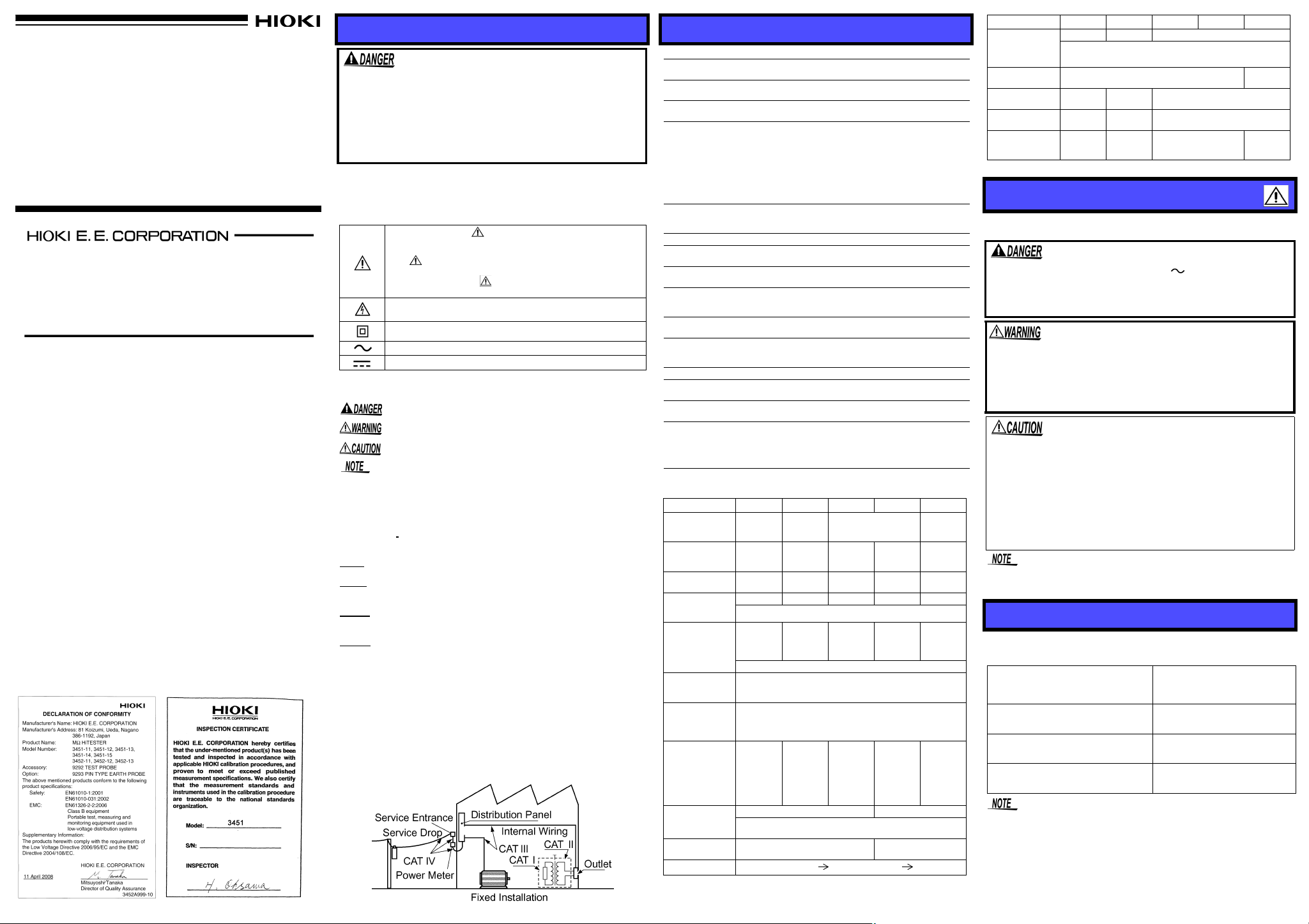
Measurement Categories (Overvoltage Categories)
This instrument conforms to the safety requirements for CAT III measurement instruments. To ensure safe operation of measurement
instruments, I
trical environments, categorized as CAT I to CAT IV, and called measurement categories. These are defined as follows.
CAT I
CAT II
CAT III
CAT IV
Higher-numbered categories correspond to electrical environments
with greater momentary energy, so a measurement instrument
designed for CAT III environments can endure greater momentary
energy than one designed for CAT II.
Using a measurement inst rument in an e nvironm ent des ignated w ith a
higher-numbered category than that for which the instrument is rated
could result in a severe accident, and must be carefully avoided.
Never use a CAT I measuring instrument in CAT II, III, or IV environments.
The measurement categories compl y wit h the Over volta ge Categories
of the IEC60664 Standards.
EC 61010 establishes safety standards for various elec-
: Secondary electrical circuits connected to an AC electrical
outlet through a transformer or similar device.
: Primary electrical circuits in equipment connected to an AC
electrical outlet by a power cord (portable tools, household
appliances, etc.)
: Primary electrical circuits of heavy equipment (fixed installa-
tions) connected directly to the distributi on panel, and feeders
from the distribution panel to outlets.
:The circuit from the service drop to the service entrance, and
to the power meter and primary overcurrent protection device
(distribution panel).
Specifications
General Specifications
Operating Temperature &Humidity
Storage T emperature
&Humidity
Operating Environment
Effect of temperature
°C
0 to 18
(32 to 64°F,82 to
104
Effect of position
(at ±90 degrees to
the horizontal):
Degree of protection IP40
Power source
Maximum rated
power
Continuous operat-
ing time
Dielectric strength
Dimensions
(excluding protrusions)
Mass 400 g, (14.11 oz.) approx. (including batteries)
Accessories
Options
Standards applying
Specifications of Each Instrument
Guaranteed for one year at 23°C±5°C (73°F ±9°F ) and 90% RH
Rated
measurement
voltage
Maximum
effective reading
Center scale
reading
1st effective
measurement
range (MΩ)
2nd effective
measurement
range (MΩ)
0 MΩ, ∞ scale
Open circuit
voltage (when
no load is
applied)
Lower limit
measurement
resistance
value to be
maintained
rated measurement voltage
Rated
measurement
current
short circuit
current
Response time
, 28 to 40
°F
)
Model 3451-11 3451-12 3451-13 3451-14 3451-15
0 to 40
°C (32 to 104°F)
(non-condensating)
-20 to 50
(non-condensating)
Indoors, <2000m (6562-ft.) ASL
• 1st effective measurement range:
• 2nd effective measurement range:
°C
• 0 MΩ, ∞scale:
• AC voltage measurement:
Variation of needle deflection from horizontal
reading not more than 2% (1.5mm) of scale
length.
Rated power voltage: 1.5 V DC X 4,
R6P manganese battery X 4
3 VA (when battery check)
3451-11: 30 h approx.3451-14: 35 h approx.
3451-12: 20 h approx.3451-15: 15 h approx.
3451-13: 10 h approx.
5550 Vrms 50/60 Hz for one minute
Between electric circuit and case
152W X 95H X 47D mm approx.
5.98"W X 3.74"H X 1.85"D approx.
9292 TEST PROBE, 9384 CARRYING CASE,
Instruction Manual, R6P manganese battery X 4
9293 PIN TYPE EARTH PROBE, 9288
BREAKER PIN
Safety EN61010
EMC EN61326
125 VDC 250 VDC 500 VDC
20 M
0.5 M
0.02 - 10 0.05 - 20 0.1 - 50 1 - 500 2 - 1000
0.01 - 0.02
10 - 20
(When needle center line is within width of scale
markings at the extreme ends of the scale.)
0.125
M
(current to be maintained rated measurement volt-
°C (-4 to 122°F)
±5% of reading, plus basic allowance
±10% of reading, plus basic allowance
±0.7% of scale length, plus basic allowance
±5% of maximum scale len gth, plus basic al low-
ance
Measurement Category III, Pollution
Degree 2
(Anticipated Transient Overvoltage: )
Ω 50 MΩ 100 MΩ 1000 MΩ 2000 MΩ
Ω 1 MΩ 2 MΩ 20 MΩ 50 MΩ
±5% of scale reading
0.01 - 0.05
20 - 50
±10% of scale reading
0.7% of scale length
1 - 1.2 times of rated measurement voltage
(open circuit terminal voltage)
0.25 MΩ 0.5 MΩ 1 MΩ 2 MΩ
Ω
1 - 1.2 mA 0.5 - 0.6 mA
1.2 mA max. 0.6 mA max.
Within 3 s (
∞ center value, ∞ 0 MΩ)
, 90%RH max.
, 90%RH max.
0.05 - 0.1
50 - 100
age)
0.5 - 1
500 -
1000
.
1000
VDC
1 - 2
1000-
2000
Model 3451-11 3451-12 3451-13 3451-14 3451-15
AC voltage
scale and
allowance (50/
60 Hz)
Input resistance
Maximum input
voltage
Maximum rated
voltage to earth
Input error
protection
for10 s
0 - 250 V 0 - 300 V 0 - 500 V
±5% of maximum scale value
110 kΩ min.
250 VAC 300 VAC 500 VAC
250 VAC 300 VAC 500 VAC
300 VAC 360 VAC 600 VAC
190 kΩ
min.
1200
VAC
Notes on Use
Follow these precautions to ensure safe operation and to obtain the
full benefits of the various functions.
• On the probe there is a label stating 600 V , ho wever t his is
only the probe's maximum rated voltage, and is not the maximum rated voltage of 3451.
• Before connecting probes to the instrument, check that the
probes are disconnected from the object to be measured.
• Do not use the instrument where it may be exposed to
corrosive or combustible gases. The in strument m ay be
damaged or cause an explosion.
• Do not allow the
instrument to get wet, and do not take
measurements with wet hands. This may cause an electric shock.
• This instrument is designed for use indoors. It can be operated at
temperatures between 0 and 40°C without degrading safety.
• Do not store or use the instrument where it coul d be exposed to di rect sunlight, high temperature or humidity , or condensation. U nder
such conditions, the instrument may be damaged and insulation
may deteriorate so that it no longer meets specifications.
• For safety reasons, when taking meas urements, onl y use the 9292
TEST PROBE provided with the instrument (or optional 9293).
• To avoid damage to the instrument, protect it from physical shock
when transporting and handling. Be especially careful to avoid
physical shock from dropping.
• When refreshing the luminou s scal e out doors, keep the meter in the
shade.
Luminous Scale
The 3451 scales are marked with a phosphorescent paint.
Once this is refreshed by exposure to light, it remains luminous for a
while, allowing measurement in a dark place.
Brightness and exposure of
refreshing light
Average living room lighting at
night
(approx. 200 lx for 5 minutes)
In the office
(approx. 1,000 lx for min. 30 seconds)
Daylight outdoor
(approx. min. 10,000 lx for min. 30
seconds)
• When using it outdoors, as far as possible keep in the shade.
• When the user moves from a light place to a dark place, because of
the time eyes take to adjust to the light, the scale may not be legibl e
immediately.
length of time scale remains
legible in the dark
(at approx. 15 cm from eye)
Approx. 5 minutes
Approx. 10 minutes
Approx. 15 minutes
Page 2
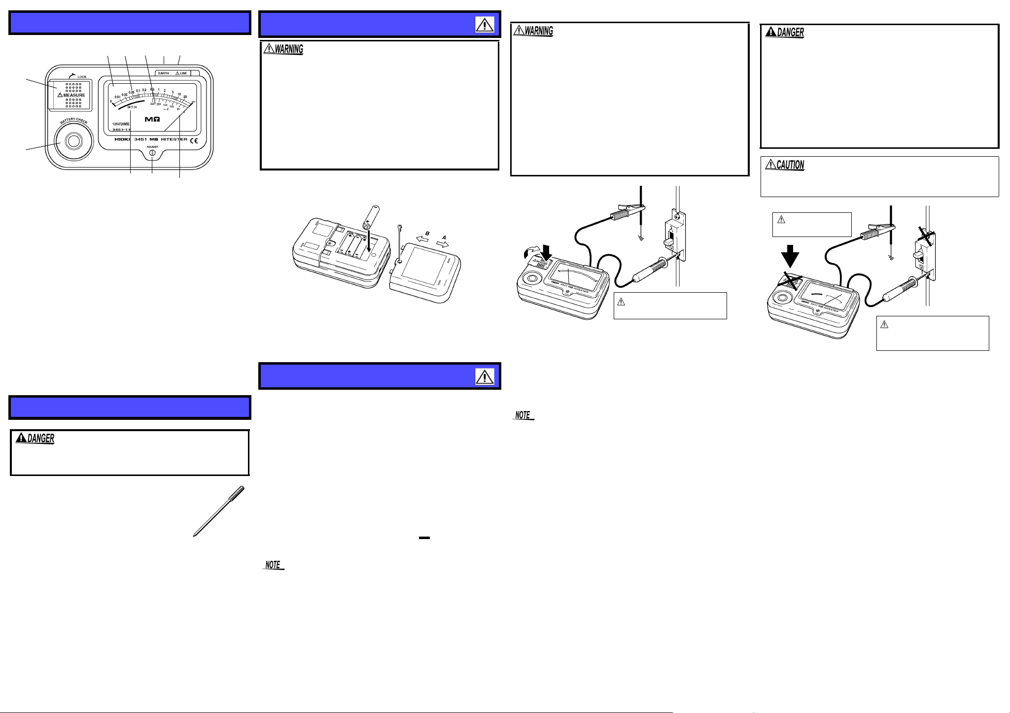
Names and Functions of Parts
1
2
3 4 5 9 10
6 7 8
Fixing screw
Battery cover
ON
OFF
Source
(primary side)
Load
(secondary
side)
Always turn off the breaker
or the measurement line
1
2
3
4
ON
OFF
Source
(primary side)
Load
(secondary
side)
Do not press the
MEASURE button.
Always connect the probe
to the secondary side of
the breaker.
1
2
3
Replacing of Batteries
z
Insulation Resistance Measurement
z
AC Voltage Me as ure ment
1.MEASURE button
Press to measure insulation resistance.
2.BATTERY CHECK button
3.Display
4.Resistance
5.AC voltage scale
6.Battery e ffective range
7.ADJUST (Zero adjust)
8.Indicator needle
9.EARTH terminal (Earth measurement terminal)
Connect the earth probe (black).
10.LINE terminal (Line measurement terminal)
Connect the line probe (red).
Using the carrying case
1.Open the cover
Remove the part of the top surface where "OPEN" is written.
Turn the cover you have removed round to the back, and attach for
use.
2.Store the instruction manual
Can be put under the 3451.
Options
To avoid electrical shock, be careful to avoid shorting
live lines with the tip of BREAKER PIN.
• 9288 BREAKER PIN
Attach this to the tip of the LINE probe or pin type
earth probes. It allows the tip to be extended,
when otherwise it would be too short to make a
measurement. (This item does not conform to
IEC 61010.)
• 9293 PIN TYPE EARTH PROBE
The black EARTH probe is a pin type probe like
the LINE probe. Use it for cases where it is not possible to clip onto
the object being measured, or for measurement inside a small cavity.
• To avoid a shock hazard, disconnect the probes before
replacing the batteries. After replacing the batteries,
replace the cover and screws before using the
ment.
instru-
• Do not mix old and new batteries, or different types of
batteries. Also, be careful to observe battery polarity
during installation. Otherwise, poor performance or
damage from battery leakage could result.
• Battery may explode if mistreated. Do not short-circuit,
recharge, disassemble or dispose of in fire.
• Handle and dispose of batteries in accordance with
local regulations.
T o avoi d corrosion fr om battery leak age, remove the ba tteries from the
instrument if it is to be stored for a long time.
1.For safety, remove the probe from the instrument.
2.Loosen the screw located at the center of the back of the instrument
and remove the battery cover.
3.Replace all four batteries.
4.Reinstall the battery cover and fasten the screw.
Measurement Procedures
Preparing for Measurement
• First release the MEASURE button, then turn the zero adjuster
(ADJUST) with a screwdriver so that needle is at the center of the
infinity mark (
• Check that the battery capacity is adequate. Replace with new bat-
teries if the battery capacity is low.
• Connect the red line probe to the LINE terminal and black earth
probe to the EARTH terminal.
• Probe plug comes with a p rote ction cov er. Remove the cov er befo re
connecting to the instrument.
Battery Check
1.Remove the probes from the obje ct being me asur ed. The end of th e
disconnected may be short-circuited or open-circuited, but if an
external voltage is applied, an accurate battery check will not be
obtained.
2.Press the BATTERY CHECK button.
3. If the needle is within the range indication ( ), the batteries can
be used. If it is to the right of the indication, replace the batteries
with new ones.
The battery check function places the heaviest current drain. Check
the battery promptly.
∞).
Observe the following to avoid electric shock, short circuits, and damage to the instrument.
• When measuring insulation resistance, dangerous voltage is applied to the measurement terminals. To avoid
electric shock, do not touch the probe.
• Never touch the object being measured immediately
after measuring. There is a danger of electric shock
from the change accumulating during high voltage testing.
• Discharge the subject conductor after measurement.
• Do not attempt to measure insulation resistance on a
live conductor. Doing so could damage the instrument
or cause an accident that might result in in jury or dea th.
Always turn off power to the conductor being mea sured
before starting
1.Connect the black eart h probe t o the gro und side of the obj ect bein g
measured.
2.Connect the red line probe to the line to be measured.
3. Press the MEASURE button. (To make continuous measurements,
pull the button up.)
4.Read the value after the needle has stabilized.
• Insulation resistance is the ratio of leakage current to applied volt-
age, and is therefore unstable. Depending on the specific object
being measured, the needle may not s tabi lize, but thi s is not a meter
malfunction.
• Press the MEASURE button fully down until a click is heard. If the
button is not pressed down fully, the needle will not move from
and a proper measurement cannot be made.
• Always release the MEASURE button after use.
Discharge Function
When measuring an insulation resistance that contains a capacitance
element, a charge proportional to the measurement voltage accumulates, and if undischarged could lead to an electric shock accident.
1.Without removin g the p robe s from the it em b eing m easu red, relea se
the MEASURE button.
2.The built-in discharge circuit automatically discharges the item.
During a discharge, the needle will return slowly to the infinity (
position.
3. The discharge is completed when the needle reaches the infinity
mark. The time required for discharge depends on the capacitance
value.
∞
∞)
• Probes should only be connected to the secondary
side of a breaker, so the breaker can prevent an accident if a short circuit occurs. Connections should
never be made to the primary side of a breaker,
because unrestricted current flow could cause a serious accident if a short circuit occurs.
• Attempting to measure voltage in excess of the maximum input voltage and maximum rated volt age to earth
could destroy the instrument and result in personal
injury or death.
• To avoid electrical shock, be careful to avoid shorting
live lines with the probe.
Never press the MEASURE button while measuring voltage. Doing
so could damage the instruments connecting.
1.Connect the black earth probe to the ground.
2.Connect the red line probe to the line to be measured.
3.Read the voltage on the V scale after the needle stabilizes.
 Loading...