

Page 1

INSTRUCTION MANUAL
3447-01
TEMPERATURE
HiTESTER
Page 2

Page 3

i
Contents
Introduction .............................................................1
Inspection ............................................................... 1
Safety Notes ...........................................................2
Usage Notes ........................................................... 5
Chapter 1 Overview 7
1.1 Product Overview ...................................7
1.2 Parts Names and Functions ................... 8
1.2.1 3447-01 TEMPERATURE HiTESTER .... 8
1.2.2 9478 SHEATH TYPE TEMPERATURE
PROBE ..............................................14
1.2.3 9479 SHEATH TYPE TEMPERATURE
PROBE ..............................................14
Chapter 2 Installation 15
2.1 Attaching the strap band .......................15
2.2 Mounting or Replacing the Batteries.....16
2.3 Connecting the Temperature Probe .....18
2.4 Connecting the RS-232C Cable ........... 21
Chapter 3 Measurement Procedures 23
3.1 Before Measurement ............................23
3.1.1 Switching the 3447-01 ON or OFF .... 23
3.1.2 Auto Power Save Function ................24
3.1.3 Date and time settings (on the 3447-01) .. 26
3.1.4 Date and Time Settings
(Using a Computer) ...........................27
Page 4

ii
3.2 Basic Temperature Measureme nt .........28
3.2.1 Recording Temperature Data
(Manual Recording Mode) .................29
3.2.2 Display Hold .......................................30
3.2.3 Switching Sensor ...............................30
3.2.4 Switching Date and Time ...................31
3.2.5 Reading Data .....................................32
3.2.6 Deleting Recorded Data .....................33
3.3 Interval Recording Mode .......................35
3.3.1 Selecting a Recording Interval ...........37
3.3.2 Starting recording ...............................38
3.3.3 Stopping Interval Recording ...............39
3.3.4 Reading Data .....................................39
3.4 Item/ID display .......................................40
3.5 Comparator Function .............................42
3.5.1 Setting Comparator Values ................42
3.5.2 Confirming Comparator Value Settings .43
3.6 Key Lock Function .................................44
3.7 Buzzer Function ....................................45
3.8 Print Function ........................................46
3.9 Data Communication with a Computer ..48
Chapter 4 Specifications 49
4.1 3447-01 TEMPERATURE HiTESTER ..49
4.2 9478 SHEATH TYPE TEMPERATURE
PROBE ..................................................53
4.3 9479 SHEATH TYPE TEMPERATURE
PROBE ..................................................54
Page 5

iii
Chapter 5 Maintenace and Service 55
5.1 Replacing the Batteries .........................55
5.2 Disposing the Lithium Battery ............ 55
5.3 Cleaning ................................................57
5.4 Service .................................................. 57
Page 6

iv
Page 7

1
Introduction
Thank you for purchasing the HIOKI "3447-01
TEMPERATURE HiTESTER". To obtain maximum performance from the product, please read
this manual first, and keep it handy for future reference.
Inspection
• When you receive the product, inspect it carefully
to ensure that no damage occurred during shipping. In particular, check the accessories, panel
switches, and connectors. If damage is evident, or
if it fails to operate according to the specifications,
contact your dealer or Hioki representative.
• Before using the product, make sure that the insu-
lation on the probes is undamaged and that no
bare conductors are improperly exposed. Using
the product in such conditions could cause an
electric shock, so contact your dealer or Hioki representative for repair.
• Before using the product the first time, verify that it
operates normally to ensure that the no damage
occurred during storage or shipping. If you find any
damage, contact your dealer or Hioki representative.
Accessories
Alkaline (LR03) batterie s..................... .............4
Strap band........... .. ....... .. .. .. .. .... .. ..... .. .. .. .... .. .. .. .1
Instruction Manual ............................................1
Page 8
2
Safety Notes
This product is designed to conform to IEC
61010 Safety Standards, and has been thoroughly tested for safety prior to shipment.
However, mishandling during use could
result in injury or death, as well as damage to
the product. Be certain that you understand
the instructions and precautions in the manual before use. We disclaim any responsibility for accidents or injuries not resulting
directly from product defects.
This manual contains information and warnings
essential for safe operation of the product and for
maintaining it in safe operating condition. Before
using the product, be sure to carefully read the following safety notes.
Safety Symbols
In the manual, the symbol indicates particularly important information that the user should
read before using the product.
The symbol printed on the product indicates
that the user should refer to a corresponding topic
in the manual (marked with the symbol) before
using the relevant function.
Indicates DC (Direct Current).
Page 9

3
The following symbols in this manual indicate the
relative importance of cautions and warnings.
Indicates that incorrect operation presents an extreme hazard that could result in serious injury or
death to the user.
Indicates that incorrect operation presents a significant hazard that could result in serious injury or
death to the user.
Indicates that incorrect operation presents a possibility of injury to the user or damage to the product.
Advisory items related to performance or correct
operation of the product.
Other Symbols
Indicates the prohibited action
Accuracy
❖
rdg.
dgt.
Indicates the reference
We define measurement tolerances in terms of
rdg. (reading) and dgt. (digit) values, with the following meanings:
(reading or displayed value)
The value currently being measured and indicated
on the measuring product.
(resolution)
The smallest displayable unit on a digital measuring product, i.e., the input value that causes the
digital display to show a "1".
Page 10
4
Measurement catego ries (O vervolt ag e categories)
This product conforms to the safety requirements
for CAT I measurement products.
To ensure safe operation of measurement products, IEC 61010 establishes safety standards for
various electrical environments, categorized as
CAT I to CAT IV, and called measurement categories. These are defined as follows.
CAT I
CAT II
CAT III
CAT IV
Secondary electrical circuits connected to an AC electrical outlet through a transformer or similar device.
Primary electrical circuits in equipment connected to an
AC electrical outlet by a power cord (portable tools,
household appliances, etc.)
Primary electrical circuits of heavy equipment (fixed installations) connected directly to the distribution panel,
and feeders from the distribution panel to outlets.
The circuit from the service drop to the service entrance,
and to the power meter and primary overcurrent protection device (distribution panel).
Higher-numbered categories correspond to electrical environments with greater momentary energy,
so a measurement product designed for CAT III
environments can endure greater momentary
energy than one designed for CAT II. Using a measurement product in an environment designated
with a higher-numbered category than that for
which the product is rated could result in a severe
accident, and must be carefully avoided.
Never use a CAT I measuring product in CAT II, III,
or IV environments.
The measurement categories comply with the
Overvoltage Categories of the IEC60664 Standards.
Page 11
5
Usage Notes
Follow these precautions to ensure safe operation
and to obtain the full benefits of the various func-
tions.
Do not attempt to measure the temperature
of objects carrying a voltage. Doing so will
result in a short-circu it a cc id ent or an el ectrocution accident.
• This product should be installed and operated
indoors only, between 0 and 40
• To avoid damaging the product, never connect
any sensor other than the 9478 or 9479
SHEATH TYPE TEMPERATURE PROBE to the
sensor connector. Never attempt to input a signal through the sensor connector. For information on the temperature range of use for
temperature probes, see 4.2 "9478 SHEATH
TYPE TEMPERATURE PROBE" (53 page) and
4.3 "9479 SHEATH TYPE TEMPERATURE
PROBE" (54 page).
• Do not store or use the product where it could
be exposed to direct sunlight, high temperature
or humidity, or condensation. Under such conditions, the product may be damaged and insulation may deteriorate so that it no longer meets
specifications.
• Do not use the product where it may be exposed
to corrosive or combustible gases. The product
may be damaged.
• Avoid using the product for long periods if the
unit is soiled with oil or dirt. Doing so may cause
the unit’s case to become warped or damage
the product.
°C and 80% RH.
Page 12

6
• The sheath of the temperature probe is filled
with magnesium oxide powder. If the probe is
broken, the magnesium oxide powder may spill
out. Be careful not to subject the sheath to
excess stress. Inhaling large quantities of magnesium oxide may be hazardous to your health.
• This product has a dust and water-resistant
construction. However, it cannot be used in
water.
• The protection rating for the enclosure of this
device (based on EN60529) is *IP67.
*IP67:
This indicates the degree of protection provided by
the enclosure of the device against use in hazardous locations, entry of solid foreign objects, and
the ingress of water.
6: Protected against access to hazardous parts
with wire measuring 1.0 mm in diameter. Dustproof type (Dust shall not penetrate the enclosure.)
7: Watertight (Quantities of water that may harm
the enclosure when it is temporarily immersed in
water shall not penetrate the enclosure.)
Page 13

7
1.1 Product Overview
Overview Chapter 1
1.1 Product Overview
The 3447-01 TEMPERATURE HiTESTER is a
water-resistant thermometer designed for use with
the platinum resistance thermometer sonsor
(Pt100).
By using the product in combination with the special 9478 SHEATH TYPE TEMPERATURE
PROBE or 9479 SHEATH TYPE TEMPERATURE
PROBE, the product is capable of temperature
measurement within the range -100
Equipped with a clock function, the product allows
you to check the time.
This product is ideal for controlling temperatures
since it allows you to record both measurement
temperatures and measurement times at the touch
of a button. (Manual Recording Mode)
Further, the product can be used as a logger for
continuous data recording at a specified recording
interval. (Interval Recording Mode)
This product can store up to 7,200 data items (in
manual recording mode), or 28,800 data items (in
interval recording mode) in its internal memory.
Because data is stored in the unit’s non-volatile
memory, data is not lost when battery power runs
low or during battery replacement.
When the product is connected to a PC via the
optional 9674 RS-232C PACKAGE, you can set
items (product names) and IDs (worker names)
from your computer, and record this information
together with temperature data.
You can also transfer recorded data to your computer and display it.
°C to 300.0 °C.
Page 14
1.2 Parts Names and Functions
8
1.2 Parts Names and Functions
1.2.1 3447-01 TEMPERATURE HiTESTER
3447-01 TEMPERATURE HiTESTER
LCD display
Buttons
RS-232C connector
(Protective cap)
Sensor connector
(Protective cap)
Strap band
attachment hole
Battery
compartment
Strap band
attachment hole
Page 15

9
1.2 Parts Names and Functions
LCD display Displays temperature readings and set-
Sensor connector Connect either the 9478 or 9479
Protective cap Place on unused connectors.
Strap band
attachment hole
Battery
compartment
RS-232C
connector
tings.
SHEATH TYPE TEMPERATURE PROBE.
For attaching the provided strap band.
The product uses 4 LR03 (AAA) alkaline
dry cell batteries.
Use the special cable provided with the
9674 RS-232C PACKAGE to connect the
unit to your computer or printer.
Page 16

10
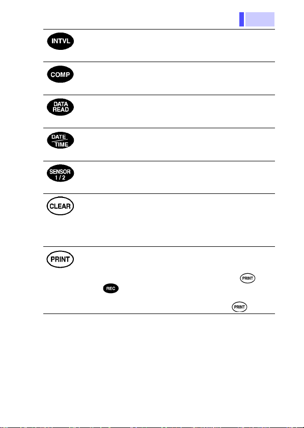
Buttons
1.2 Parts Names and Functions
●Manual Recording Mode
Records temperature and time readings.
●Interval Recording Mode
Starts and stops interval recording.
Activates the display hold function.
Turns the 3447-01’s power on/off. (Press for 2
seconds)
• Selects Item or ID type.
• Selects a data number for reading.
• Changes date/time settings.
• Selects the recording interval.
Toggles between Item display and ID display.
Page 17
11
K
ey lock
s
(Press for 2
econds)
1.2 Parts Names and Functions
Sets the recording interval for interval recording.
When this is off, manual recording is selected.
Displays comparator value settings.
Displays recorded data.
Toggles the display between date and time.
Sets date and time. (Press for 2 seconds)
Toggles temperature display between Sensor 1
and sensor 2.
●Delete most recent data
Deletes the most recent data item.
●Delete all data
Deletes all recorded data.
Cancels all settings in all settings screens, and
returns the monitor screen.
●Print
Sends recorded data to a printer.
●Key lock (Manual recording)
Inhibits operation of all keys except and
.
●Key lock (Interval recording)
Inhibits operation of all keys except .
Page 18
1.2 Parts Names and Functions
12
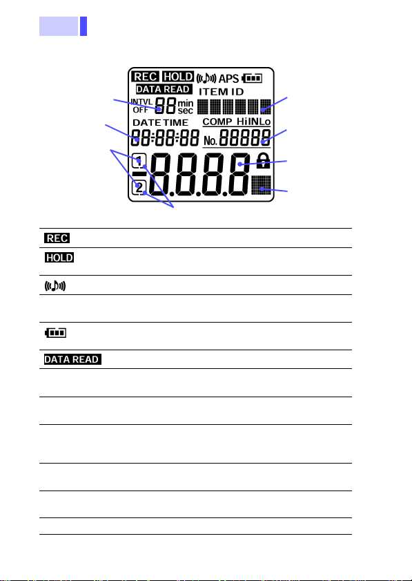
LCD display
t
Recording
interval display
Date and time
display
Sensor number
Sensor identification mark
Indicates that recording is taking place.
Indicates that the display hold function is
activated.
Indicates that the buzzer is on.
APS Indicates that the auto power save function
is on.
Displays the remaining battery charge in 4
steps.
Indicates data read mode.
ITEM Indicates that the item (product name) is
ID Indicates that the ID (worker name) is
being displayed.
being displayed.
INTVL Indicates that the 3447-01 is in interval
recording mode or in recording interval
setting mode.
Recording interval
Displays the recording interval.
display
Text display Displays text (alphanumeric) set as Items
or IDs.
DATE Indicates date display.
Text display
Data number
display
Temperature
measuremen
display
Unit display
Page 19

13
1.2 Parts Names and Functions
TIME Indicates time display.
Date and time
display
COMP Hi IN Lo Indicates comparator settings mode, or
Data number
display
Sensor number Indicates the number for the connected
Sensor
identification mark
Temperature
measurement
display
Unit display
Displays the date or time.
comparator test results.
Displays a number for a data item.
sensor.
Indicates the sensor displayed in the tem-
perature display.
Displays temperature measurement.
Displays comparator value settings.
(comparator confirm mode)
Indicates that the key lock function is activated.
Indicates the units (
display.
°C) for the temperature
Page 20
1.2 Parts Names and Functions
14
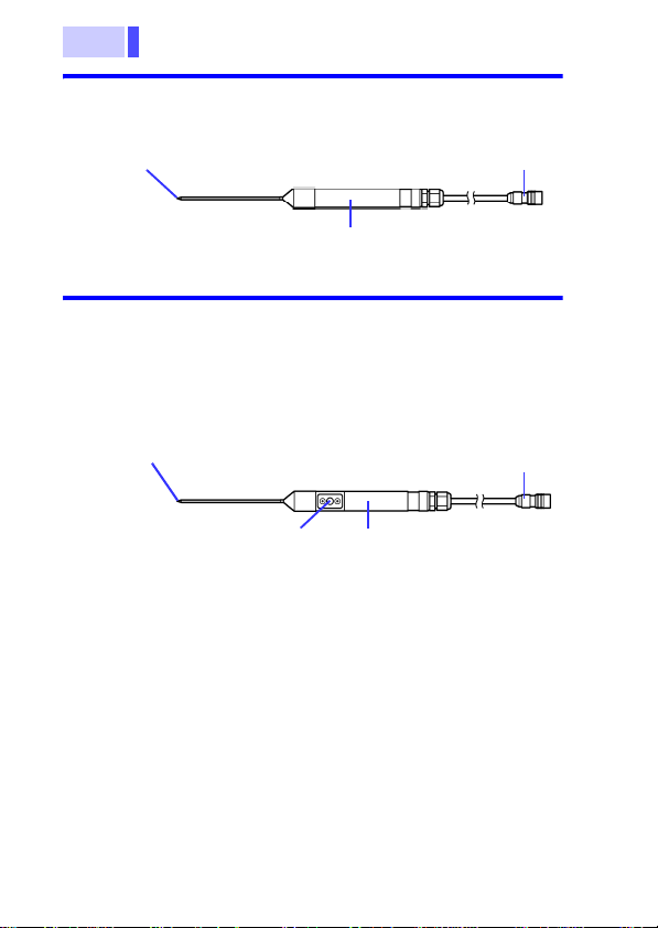
1.2.2 9478 SHEATH TYPE TEMPERATURE PROBE
Measuring point
Grip
Sensor connector
1.2.3 9479 SHEATH TYPE TEMPERATURE PROBE
With the 3447-01 you can record temperatures in
the same manner using the button on the temperature probe’s grip, or the button on the 3447-01
itself.
Measuring point
Sensor connector
Recording button
Grip
Page 21

15
2.1 Attaching the strap band
Installation Chapter 2
2.1 Attaching the strap band
You can attach the strap band provided with the
product. There are holes on the top and bottom of
the product. Attach the strap handle to these holes
as necessary.
Page 22

2.2 Mounting or Replacing the Batteries
16
2.2 Mounting or Replacing the
Batteries
• Do not mix old and new batteries, or different types of batteries. Also, be careful to
observe battery polarity during installation.
Otherwise, poor performance or damage
from battery leakage could result.
• After replacing the batteries, replace the
cover and screws before using the product.
• Failure to properly close the unit’s battery
compartment cover w ill ca use los s of water
resistance.
• To avoid the possibility of explo sion, do not
short circuit, disassemble or incinerate batteries.
• Handle and dispose of batteries in accordance with local regulations.
• The “ ” indicator appears when battery volt-
age becomes low. Replace the batteries as soon
as possible.
• To av oid corrosion from battery leakage, remove
the batteries from the product if it is to be stored
for a long time (several months or more).
• To prevent recorded or settings data from being
destroyed, always switch off the power before
replacing the batteries.
• The unit’s battery compartment and battery cover
are fitted with rubber rings. After replacing the
battery, check that the rubber rings are properly
seated before reinstalling the battery cover.
Improper seating of the rubber rings will compromise the unit’s water-resistant structure, and
possibly result in damage to the equipment.
Page 23

17
2.2 Mounting or Replacing the Batterie s
New batteries should last for about 15 days of continuous use, with the auto power save function
switched off. Batteries should last for about 1
month or more of continuous recording using th e
product in interval recording mode (with the
recording interval set to 1 minute or longer), and
with the auto power save function switched on.
(When using the product at 20
During interval recording, recording stops when
batteries wear out.
Remaining battery charge display
The display disappears from the
right side as the remaining battery
charge decreases.
Time to replace batteries. There is
no charge remaining in the batteries.
Mounting or replacing the batteries
1. Remove back cover
screw to remove cover.
Verify polarity and install
four new LR03 alkaline
batteries.
2. Fit cover properly and
tighten screw.
°C)
Page 24

2.3 Connecting the Temperature Probe
18
2.3 Connecting the Temperature Probe
• To avoid damage to the product, protect it from
vibration or shock during transport and handling,
and be especially careful to avoid dropping.
• To avoid damaging the product, never connect
any sensor other than the 9478 or 9479
SHEATH TYPE TEMPERATURE PROBE (with
recording switch) to the sensor connector.
Never attempt to input a signal through the sensor connector.
• The ends of the probes are sharp. Be careful to
avoid injury.
• When disconnecting the temperature probe, be
sure to release the lock before pulling off the
connector. Forcibly pulling the connector without
releasing the lock, or pulling on the cable, can
damage the connector.
• To avoid damaging the probes, do not bend or
pull the probes.
• Keep the cable well away from heat sources, as
bare conductors could be exposed if the insulation melts.
• Improper connecting of a connector will permit
passage of moisture into the device and dam age it.
• Do not bend the temperature probe’s measuring
element (the metallic portion). Doing so is likely
to cause damage.
Page 25

19
2.3 Connecting the Temperature Probe
• The sensor used in the temperature probe is a
precision platinum element. Please note that
excessive voltage pulses or static discharges
can destroy the element.To avoid damage or
malfunction, avoid hitting the tip of the temperature probe and overly bending the leads.
When measuring high temperatures, do not let
the handle of the temperature probe or the cable
exceed the temperature range.
• Make sure that temperatures do not exceed
those rated for the temperature probe handle
and cable.
• The temperature probe has a protective nylon
cap fitted on the end of the probes. Remove the
cap before using the probe.
• Put the protective cap back on the connector
when not in use. If the protective cap is not
properly inserted, dust or other foreign matter
may enter the connector and cause damage.
• The sheath of the temperature probe is filled
with magnesium oxide powder. If the probe is
broken, the magnesium oxide powder may spill
out. Be careful not to subject the sheath to
excess stress. Inhaling large quantities of magnesium oxide may be hazardous to your health.
Page 26

2.3 Connecting the Temperature Probe
20
Connecting the temperature probe
Coupling
To remove the temperature probe, grip the connector coupling and pull
it straight out to remove
it.
1. To lock the connector, grip
the connector and turn the
arrow upwards until you
hear a click.
2. Hold the connector (not by
the coupling) and lightly pull
it to confirm that it is properly connected.
Insert the protective cap
into the sensor connectors
when not connecting a
temperature probe.
Protective cap
Page 27

21
2.4 Connecting the RS-232C Cable
2.4 Connecting the RS-232C Cable
Using the optional 9674 RS-232C PACKAGE, you
can connect the product to a computer or a printer
for exchange of data.
• To avoid damaging the product, never connect
any cable other than the supplied cable to the
RS-232C connector.
• When disconnecting the RS-232C cable, be
sure to release the lock before pulling off the
connector. Forcibly pulling the connector without
releasing the lock, or pulling on the cable, can
damage the connector.
• To avoid damaging the cable, do not bend or
pull the cable.
• Avoid stepping on or pinching the cable, which
could damage the cable insulation.
• Keep the cable well away from heat sources, as
bare conductors could be exposed if the insulation melts.
• The RS-232C cable is not dust or water resistant. Do not use RS-232C communication in
environments that are very dusty or exposed to
water. Doing so is likely to result in damage.
• Leaving the product connected to a computer
that is running will cause the batteries to wear
out faster than usual. Do not connect the product to a computer if there is no data transfer.
Make sure connectors and protective caps are
always properly inserted. If the connector or protective cap is not properly inserted, dust or other
foreign matter may enter the connector a nd ca use
damage.
Replace the protective cap when not using the
connector.
Page 28

2.4 Connecting the RS-232C Cable
22
Connecting the RS-232C cable
Coupling
1. To lock the connector, grip
2. Hold the connector (not by
To remove the RS-232C
cable, grip the connector
coupling and pull it
straight out to remove it.
Protective cap
the connector and turn the
arrow upwards until you
hear a click.
the coupling) and lightly
pull it to confirm that it is
properly connected.
Insert the protective cap
into the RS-232C connectors when not connecting a
RS-232C cable.
Page 29

23
3.1 Before Measurement
Measurement
Procedures
Do not attempt to measure the temperature
of objects carrying a voltage. Doing so will
result in a short-circu it a cc id ent or an el ectrocution accident.
3.1 Before Measurement
3.1.1 Switching the 3447-01 ON or OFF
Press for about 2 seconds.
The whole LCD goes on for 2 seconds, the monitor
screen appears and the temperature is displayed.
Chapter 3
Whole LCD goes on
Press again for 2 about seconds to switch the
3447-01 off.
Monitor screen
Page 30

3.1 Before Measurement
24
If the message “ERROR!” appears when the
power is turned on, the unit’s settings may not
have been saved properly. Cycling the power off
once, and then on again can ordinarily restore
normal operation. If this does not restore normal
operation, equipment failure is possible. Contact
the store from which you purchased the unit for
assistance.
3.1.2 Auto Power Save Function
With the auto power save function switched on,
the power is automatically switched off if no button
is pressed for approximately 10 minutes.
As the default setting, the auto power save function is switched on. ("APS" lights)
Switching the auto power save function from OFF to ON
1. While pressing , press for about
2 seconds to turn the power on.
2. "APS" lights on the LCD. The auto power
save function is now switched on.
Switching the auto power save function from ON to OFF
1. While pressing , press for about
2 seconds to turn the power on.
2. "APS" disappears on the LCD. The auto
power save function is now switched off.
Page 31

25
3.1 Before Measurement
Even with the auto power save function activated
and the power off, setting of auto power save function is saved.
With the auto power save function on during interval recording, the LCD (temperature display and
so on) goes off, and only “ ” and “ ” are
displayed. Temperature measurement and recording still continues. To release the auto power save
mode, press any switch to turn on the display and
return to the monitor screen.
Interval recording
(With auto power save ON)
Page 32

3.1 Before Measurement
26
3.1.3 Date and time settings (on the 3447-01)
Check the date and time displayed on the product.
Since the clock function is backed up in the product, time is not reset when changing batteries.
However, the accuracy of the internal clock may
deviate after long periods of use. If the time deviates, follow the procedure below to reset the time.
You can set the date and time easily on the product.
Seting the date and time
1. Press for about 2 seconds to
turn the power on.
2. In the monitor screen, press
for about 2 second. "DATE" lights,
and the product is ready for date
setting.
Date settings mode
(year setting)
3. "Year" flashes. Press / to
set the year.
4. Complete the date and time set-
ting in the same way, by pressing
, and setting each item as it
flashes, in the order
"year"→"month"→"day"→"hour"
Time setting mode
(hour setting)
→"minute"→"second." When set-
ting the time (hour, minute, second) "TIME" lights.
5. Set the seconds, and press .
The settings are complete, and
the monitor screen returns.
Until the date and time settings are complete, the
monitor screen returns if you press any key other
than or / .
Page 33

27
3.1 Before Measurement
3.1.4 Date and Time Settings (Using a Computer)
You can set the date and time from a computer
with the product connected via the optional 9674
RS-232C PACKAGE. The 9674 COMMUNICATION UTILITY must be installed into the computer.
For details about installing and operating the software, refer to the 9674 Instruction Manual.
Page 34

3.2 Basic Temperature Measurement
28
3.2 Basic Temperature Measurement
This section describes basic temperature measurement procedures and data recording (in manual recording mode).
The temperature sensor is located at the end of
the metal sheath of the 9478, 9479 SHEATH
TYPE TEMPERATURE PROBE. To accurately
test internal temperature, insert the probe into the
item you want to measure to a distance at least 15
to 20 times the diameter of the sheath.
OK
Internal
temperature
measurement.
15D to 20D
D
Page 35

29
3.2 Basic Temperature Measurement
3.2.1 Recording Temperature Data (Manual Recording Mode)
You can record temperature as well as time.
Turn off the recording interval.
3.3.1 "Selecting a Recording Interval" (37 page)
When using the product in only manual recording
mode, it possible to record up to 7200 data items
(single channel) or 4800 entries (dual channel).
To record a temperature in the product’s internal
memory, Press . " " appears on the display, and the temperature displayed on the LCD is
recorded.
To record a temperature with the 3447-01 in manual recording mode, you can press on the
product, or press the button on the handle of the
9479 SHEATH TYPE TEMPERATURE PROBE.
Upon pressing , the temperatures for both
sensor 1 and sensor 2 are simultaneously
recorded.
If there is no data recorded, 0 appears for the data
number. The data number counts up each time
you press , indicating the number of data
items.
No data recorded
(data number 0)
Data recorded
(data number 1)
Recording button
9479 SHEATH TYPE TEMPERATURE PROBE
Page 36

3.2 Basic Temperature Measurement
30
3.2.2 Display Hold
Upon pressing , " " lights, and the displayed temperature and time are held.
To release the display hold function, press .
" " goes off.
Pressing while product is display hold mode
records the temperature and time displayed, and
then releases the display hold function.
Pressing during int erval recording only holds
the display. Interval recording continues. Press
to release the display hold function.
You can use the , and keys while
the product is in the display hold state.
3.2.3 Switching Sensor
You can connect either the 9478 or 9479 SHEATH
TYPE TEMPERATURE PROBEs to the 3447-01.
The number for the connected sensor is displayed
on the LCD screen. However, only the measurement for either sensor 1 or sensor 2 is displayed at
one time.
Press to toggle the temperature measurement display between the sensors. Anidentification
mark appears for the sensor number, indicating
which sensor’s temperature is displayed.
Sensor 1 displayed
Sensor 2 displayed
Page 37

31
3.2 Basic Temperature Measurement
3.2.4 Switching Date and Time
Upon turning on the power, "TIME" lights, and the
time is displayed.
Press to toggle between date and time display.
Time display
Date display
Page 38

3.2 Basic Temperature Measurement
32
3.2.5 Reading Data
You can read data stored in the product’s memory.
Reading data
1. In the monitor screen, press ,
2. Press , "SPACE" lights, and the
Data reading
(data number 7000)
Remaining memory
display
(3000 available data
items)
3. Each time you press , the data
4. To finish data reading, press any
" " lights, and the most
recently recorded data appears.
available memory (the number of
empty data items) appears.
number counts up from data number 1 and the corresponding data
appears.
Each time you press , the data
number counts down from the
most recent data item, and the
corresponding data appears.
If there is a large number of data
items, hold down / to automatically scroll through the data.
Auto-scroll stops when you
release the button.
button other than / to return
to the monitor screen.
Page 39

33
3.2 Basic Temperature Measurement
3.2.6 Deleting Recorded Data
Deleting the most recent data item
To delete unwanted data or data resulting from
accidental depression of the button, follow
the procedure below to delete the most recent data
item.
With sensors 1 and 2 connected, the data item for
both sensors is deleted.
Deleting recorded data (most recent data)
1. In the monitor screen, press
. The clear data screen
appears and "CLEAR?" is displayed.
2. Press to delete the most
recent data item.
Clear data screen
(Deleting the most
recent data item)
3. After deleting the data, the
monitor screen returns.
Page 40

3.2 Basic Temperature Measurement
34
Deleting All Data
When there is no more internal memory available,
"FULL" is displayed for the data number. Further
recording is not possible.
After storing the data in a computer or sending it to
a printer, follow the procedure below to delete all
data.
Deleting recorded data (all data)
1. While holding down ,
Internal memory
full
2. The clear data screen
3. Press to delete all data.
Clear data screen
(Deleting all data)
press the button for about
2 seconds to turn the power
on.
appears, and "CLEAR? ALL"
is displayed.
Press any button other than
or to return to the
monitor screen.
Page 41

35
3.3 Interval Recording Mode
3.3 Interval Recording Mode
Select a recording interval to record temperature
at a specified interval.
Both manual recording data and interval recording
data can be saved in the product together.
If you only use interval recording, the following limitations apply to the recording interval and the
maximum recording time:
With single channel recording, the maximum num ber of data items is 28800 per product.
INTVL. REC. time INTVL. REC. time
1 sec 8 h 1 min 20 d
2 sec 16 h 2 min 40 d
5 sec 1 d 16 h 5 min 100 d
10 sec 3 d 8 h 10 min 200 d
15 sec 5 d 15 min 300 d
20 sec 6 d 16 h 20 min 400 d
30 sec 10 d 30 min 600 d
60 min 1200 d
d: day(s), h: hours
Page 42

3.3 Interval Recording Mode
36
With dual channel recording, the maximum of data
items is 14400 per product.
INTVL. REC. time INTVL. REC. time
1 sec 4 h 1 min 10 d
2 sec 8 h 2 min 20 d
5 sec 20 h 5 min 50 d
10 sec 1 d 16 h 10 min 100 d
15 sec 5 d 15 min 150 d
20 sec 2 d 12 h 20 min 200 d
30 sec 5 d 30 min 300 d
60 min 600 d
d: day(s), h: hours
The amount of continuous recording time available
is limited by remaining battery charge.
Page 43

37
3.3 Interval Recording Mode
3.3.1 Selecting a Recording Interval
Selecting a recording interval
1. In the monitor screen, press
to display the interval
recording screen. "INTVL"
appears.
2. Press / to select a
Interval recording
screen
(No recording interval)
Interval recording
screen
(30 second recording
interval set)
recording interval. The default
setting is "OFF" (manual
recording). The recording interval display switches as follows:
"OFF" (manual recording)→
"1sec" (1 second)→"2sec"→
"5sec"→"10sec"→"15sec"→
"20sec"→"30sec" (30seconds)
→"1min" (1 minute)→"2min"
→"5min"→"10min"→"15min"
→"20min"→"30min"→"60min"
→"OFF" (manual recording).
3. Press to return to the
monitor screen.
With any setting other than
"OFF", "INTVL" is displayed on
the screen, and the product is
set for interval recordi n g.
Page 44

3.3 Interval Recording Mode
38
3.3.2 Starting recording
With interval recording, you can start up to 16 new
recordings. Confirm that the product is ready for
interval recording.
3.3.4 "Reading Data" (39 page)
In the monitor screen, press . " " lights
and recording commences.
Only the button on the product is available
with interval recording. You cannot use the button
on the handle of the 9479 SHEATH TYPE TEMPERATURE PROBE.
When there is no recorded data, 0 appears for the
data number. The data number counts up with
each successive interval during interval recording,
hence displaying the number of data items.
It is not possible to turn the power off during inter-
val recording, even by pressing . Stop interval
recording before turning the power off.
Interval recording (data number 7000)
Page 45

39
3.3 Interval Recording Mode
3.3.3 Stopping Interval Recording
To stop the interval recording, press a second
time (while the " " indicator is on).
Recording stops automatically if the product’s
internal memory becomes full (when "FULL" is displayed for the data number).
Recording stops automatically if the batteries run
out during interval recording.
3.3.4 Reading Data
3.2.5 "Reading Data" (32 page)
With interval recording (when "INTVL" is displayed), the number available interval recording
sequences, and the amount of available memory
(the remaining number of empty data items) is displayed upon reading data.
If 0 is displayed for the number of available recording sequences, interval recording is not possible.
Delete data and then commence recording.
(maximum 16 interval recording sequences).
Remaining memory display
Page 46

3.4 Item/ID display
40
3.4 Item/ID display
On the 3447-01’s display, you can display text for
Items (product names) and IDs (worker names)
first registered on a computer, and record items
and IDs with temperature recordings.
The display is capable of displaying up to 6 characters (alphanumeric) at one time. However, by
scrolling the text, you can display registrations up
to 12 characters long.
You can set separate items for sensors 1 and 2.
However, both sensors share the ID that you set.
You can register a maximum of 300 items, and a
maximum of 100 IDs.
9674 RS-232C PACKAGE Instruction manual
Page 47

41
Displaying Item/ID
ITEM display
(Item: Fridge)
ID display
(ID: Hioki)
3.4 Item/ID display
1. Upon turning on the power,
"ITEM" lights, and an Item
appears on the monitor screen.
2. Upon pressing , "ID" lights
and an ID appears.
If there is no item or ID data
registered, "------" is displayed.
3. With ITEM displayed ("ITEM"
lights), press / to scroll
through registered items and
select the item you want.
With ID displayed ("ID" lights),
press / to scroll through
registered IDs and select the
ID you want. Press to scroll
in the forward direction, and
to scroll in the reverse
direction.
If there is a large number of
Item or ID registrations, hold
down / to automatically
scroll through the data. Autoscroll stops when you release
the button.
Page 48

3.5 Comparator Function
42
3.5 Comparator Function
You can configure the comparator function using
the 9674 RS-232C PACKAGE.
The comparator function tests whether the temperature is within a predetermined temperature range,
and displays a test result on the LCD. If the temperature is outside the range, the buzzer sounds.
The following conditions apply to comparator value
settings (upper and lower temperature limits) and
test results: In manual recording mode, the comparator function checks the temperature at the
time of recording. During interval recording, the
comparator function checks the temperature currently on the display.
Comparator criteria Test result Buzzer
Temperature<lower limit Lo Yes
Lower limit temperature
upper limit
Upper limit<temperature Hi Yes
You can set comparator values for individual Items
(product names).
3.5.1 Setting Comparator Values
IN No
For details about setting comparator values, refer
to the Instruction Manual provided with the 9674
RS-232C PACKAGE.
Page 49

43
3.5 Comparator Function
3.5.2 Confirming Comparator Value Settings
You can check the comparator value settings on
the product.
Confirming comparator value setting
1. In the monitor screen, press
to display the comparator
confirmation screen. "COMP
Lo" (the lower temperature
limit) appears.
Comparator confirma tion screen
(Lower limit display)
2. Press to display "COMP
Hi" (the upper temperature
limit).
3. To close the comparator confir-
mation screen and return to the
monitor screen, press any button.
Comparator confirmation screen
(Upper limit display)
Page 50

3.6 Key Lock Function
44
3.6 Key Lock Function
You can use the key lock function to prevent the
product’s settings from being accidentally altered.
Switching the key lock function ON
Press (key lock) fo r at least 2 seconds. " " lights, indicating that the key
lock function is activated.
Switching the key lock function OFF
Press (key lock) fo r at least 2 seconds. " " lights, indicating that the key
lock function is released.
If interval recording is OFF and the key lock function is activated, only operation of and
(press for 2 seconds) is possible.
With interval recording set to anything other than
OFF and the key lock function activated, only
operation of (press for 2 seconds) is possible.
To perform other operations, first release the key
lock function.
Page 51

45
3.7 Buzzer Function
3.7 Buzzer Function
The product comes equipped with a miniature
buzzer, which sounds upon pressing buttons or
when the comparator function detects a temperature outside the set range.
As the default setting, the buzzer is switched on.
(" "lights)
Switching the buzzer from OFF to ON
1. While pressing , press the for
about 2 seconds to turn the power on.
2. " " appears on the LCD and the buzzer
is switched on.
Switching the buzzer from ON to OFF
1. While pressing , press the for
about 2 seconds to turn the power on.
2. " " disappears on the LCD and the
buzzer is switched off.
The buzzer setting is saved even if when the
power is switched off.
Page 52

3.8 Print Function
46
3.8 Print Function
You can connect the product to an RS-232 compatible printer via the cable provided with the
optional 9674 RS-232C PACKAGE, and print out
the data stored in the product’s memory. For
details about operating the printer, refer to the
Instruction Manual for the printer.
Printing data
1. Using the RS-232C cable pro-
2. In the monitor screen press
Print confirmation
3. Press again, "PRINT"
4. The monitor screen returns
Printing
vided with the 9674, connect
the product to a printer.
. "PRINT?" appears on the
display.
appears, and the data is sent
to the printe r.
when printing finishes.
You can cancel printing by
pressing during printing.
Specifications for printers compatible with the
3447-01 are as follows:
Check the specifications and settings before connecting the product to the printer.
Page 53

47
3.8 Print Function
Interface RS-232C
Characters per line Greater than 40 characters
Transmission
speed
Data bit 8 bit
Parity No
Stop bit 1 bit
Flow control Xon/Xoff
Optional printer 9670 PRINTER
The connector of the RS-232C cable provided with
the 9674 has the following pin configuration:
Connector type: Dsub-9 pin (female)
Pin No. Signal name Function
1 NC Not connected
2 TxD Send data
3 RxD Receive data
4 NC Not connected
5 GND Ground
6 NC Not connected
7 NC Not connected
8 NC Not connected
9 NC Not connected
19200 bps
With some types of printer, an adapter is required
between the cable and the printer.
With the optional 9670 printer, please connect the
following adapter between the cable and the
printer.
Dsub-9 pin (male)
↔Dsub-25pin (male)
Page 54

3.9 Data Communication with a Computer
48
3.9 Data Communication with a Computer
The optional 9674 RS-232C PACKAGE enables
data transfer between the product and a computer.
The 9674 communication utility must be installed
into the computer. For details about installing and
operating the software, refer to the 9674 Instruction Manual.
Page 55

49
4.1 3447-01 TEMPERATURE HiTESTER
Specifications Chapter 4
4.1 3447-01 TEMPERATURE HiTESTER
Sensor types Platinum resistance thermometer sensor
Measuring current 0.5 mA
Number of inputs 2 ch
Measurement range
Resolution
Accuracy
Sampling rate 1 time/s
Recording function Temperature recording by key operation
Recording con tent Time, temperature, Item, ID, comparator
Recording modes Manual recording
Number of possible
data items
Interval recording 1/ 2/ 5/ 10/ 15/ 20/ 30 sec
Item display 6 character (alphanumeric) item display
Pt 100 (3 wires)
-100.0 to 300.0
°C
0.1
±0.1%rdg.±0.4
(Recording also possible via the button
on the handle of the 9479 SHEATH
TYPE TEMPERATURE PROBE.)
test result.
(Recording by manual key operation)
Interval recording
(Automatic recording at a set interval.)
Manual recording
(Max. 7200:1ch, 4800:2ch)
Interval recording
(Max 28800:1ch, 14400:2ch)
1/ 2/ 5/ 10/ 15/ 20/ 30/ 60 min, OFF
(Max. 300 registrations)
Max 12 character display when scrolled.
Item registration via a computer with special software installed.
°C
°C
Page 56

4.1 3447-01 TEMPERATURE HiTESTER
50
ID display 6 character (alphanumeric) ID display
Clock function Built-in real time clock (year, month, day,
Display LCD display
(Max. 100 registrations)
Max.12 character display when scrolled.
ID registration via a computer with special software installed.
hour, minute, second)
Configurable on the product, or from a
computer with special software installed.
: recording
: hold
: buzzer
APS: auto power save function ON
: remaining battery charge (4 stages)
: data reading
ITEM: ITEM(6 characters)
ID: ID (character)(key operation to toggle
between ITEM and ID display)
INTVL: interval recording
DATE: date
TIME: time (Key operation to toggle
between Date and Time display)
COMP: comparator setting
Hi IN Lo: comparator test result
No.: recorded data item number
1 2: channel number (key operation to
toggle between the temperature reading
for each channel)
Temperature reading (4 digits)
: key lock
°C: unit
Auto power save
function
Display hold function Key operation to hold the temperature
Automatically switches the power of if no
key is pressed for 10 minutes.
Interval recording continues, although the
LCD goes off.
Auto power save is released upon pressing any key.
display
Page 57

51
4.1 3447-01 TEMPERATURE HiTESTER
Data read Key operation to display recorded data,
Comparator Displays Hi/IN/Lo for upper and lower
Data delete Key operation to delete most recent data
Back-up Temperature data, ITEM, ID comparator
Communications
interface
Computer software Data display, graph display, Item registra-
Power supply Four alkaline (LR03) batteries
Rated supply voltage DC1.5 V x 4
Maximum rated
power
recorded time and data number.
limits of temperature range set for individual items.
Comparator values configurable form a
computer with special software installed.
Value display
LCD display for test results, and buzzer
output
Hi: Upper limit < measured temperature
IN: Lower limit measured temperature
upper limit
Lo: measured temperature < lower limit
item or all data items.
Data deletion also possible from a computer with special software installed.
value settings are saved in non-volatile
memory even when batteries wear out.
Clock data (uses a lithium battery)
Communications with a computer via RS232C (using a special cable)
Output to printer (supports commercially
available RS-232 printers, using a special
cable)
tion, ID registration, Comparator settings,
printing
Data output (CSV format), data deletion,
clock settings, communication settings
60 mVA
Page 58

4.1 3447-01 TEMPERATURE HiTESTER
52
Continuous
operating time
Approx. 15 days (at 20
save
function: OFF)
Approx. 1 month (at 20
°C, auto power
°C, auto power
save
function: ON, recording interval: 1 min)
Size Approx. 66W x 150H x 31.5D mm
Weight Approx. 240 g (8.5 oz.) (
(2.60"W x 5.91"H x 1.24"D)
without protrusions
(
)
within batteries
Accessories Four alkaline (LR03) batteries
Strap band
Instruction Manual
Options
Operating temperatur e
& humidity
Storage tempe rat ure
& humidity
Operating temperature & humidity for
guaranteed
accuracy
Guraranteed
accuracy period
Operating
9478 SHEATH TYPE TEMPERATURE PROBE
9479 SHEATH TYPE TEMPERATURE PROBE
9674 RS-232C PACKAGE
9386-01 CARRYING CASE
9670 PRINTER
9671 AC ADAPTER (for the 9670)
9237 RECORDING PAPER (for the 9670)
°C, 80%RH or less
0 to 40
(non-condensating)
-10 to 50
°C, 80%RH or less
(non-condensating)
°C, 80%RH or less
0 to 40
(non-condensating)
1 year
Indoors, <2000 m (6562-ft.) ASL
environment
Standards
applying
Safety EN61010
Pollution Degree 2
Measurement Category I (330 V)
EMC
EN61326
Water resistant: EN60529:1991, IP67
)
Page 59

53
4.2 9478 SHEATH TYPE TEMPERATURE PROBE
4.2 9478 SHEATH TYPE TEMPERATURE PROBE
Sensor type Platinum resistance thermometer sensor
Accuracy
Measuring current 0.5 mA
Measurement
range
Temperature
sensor dimensions
Temperature
sensor length
Temperature
sensor material
Grip heat
resistance
Cable heat
resistance
Cable length Approx. 1000 mm (39.37")
Insulation
resistance
Water-resistant EN60529:1991
Pt 100 (3 wires)
IEC751, class A
°C±0.002t
±0.15
(t: measurement temperature)
-100 to 300
Approx. φ2.3 mm (φ0.09")
Approx. 100 mm (3.94")
SUS316
°C
80
120
More than 10 MΩ (DC250 V)
IP67
°C
°C
Page 60

4.3 9479 SHEATH TYPE TEMPERATURE PROBE
54
4.3 9479 SHEATH TYPE
TEMPERATURE PROBE
Sensor type Platinum resistance thermometer sensor
Accuracy IEC751, class A
Measuring current 0.5 mA
Measurement
range
Temperature
sensor dimensions
Temperature
sensor length
Temperature
sensor material
Grip heat
resistance
Cable heat
resistance
Cable length Approx. 1000 mm (39.37")
Insulation
resistance
Water-resistant EN60529:1991
Others Equipped with recording button
Pt 100 (3 wires)
°C±0.002t
±0.15
(t: measurement temperature)
-100 to 300
Approx. φ2.3 mm (φ0.09")
Approx. 100 mm (3.94")
SUS316
°C
80
120
More than 10 MΩ (DC250 V)
IP67
°C
°C
Page 61

55
5.1 Replacing the Batteries
Maintenace and
Service
5.1 Replacing the Batteries
2.2 "Mounting or Replacing the Batteries"
(16 page)
5.2 Disposing the Lithium Battery
• To avoid the possibility of explosion, do not
short circuit, disass em bl e or in ci nera te ba tteries.
• The product uses a lithium battery for clock
data backup.
• When disposing of this product, remove
the lithium battery and dispose of battery
and product in accordance with local regulations.
The following tools are required to remove the
lithium battery:
Phillips screwdriver, wire cutters
Chapter 5
Page 62

5.2 Disposing the Lithium Battery
56
Disposing the lithium battery
Bottom case
1. Turn the 3447-01 off.
2. Using the Phillips screw-
driver, unscrew the 6
screws from the back of
the product and remove
the bottom case.
Top case
Cut
3. Using the wire cutters,
cut the cables, and
remove the circuit board
from the case.
4. Use the wire cutters to
cut the battery terminal
mounted on the back of
the circuit board.
Back of the circuit board
This product contains a CR Coin Lithium Battery which contains
Perchlorate Material - special handling may apply.
See www.dtsc.ca.gov/hazardouswaste/perchlorate
CALIFORNIA, USA ONLY
Page 63

57
5.3 Cleaning
To clean the product, wipe it gently with a soft cloth
moistened with water or mild detergent. Never use
solvents such as benzene, alcohol, acetone, ether,
ketones, thinners or gasoline, as they can deform
and discolor the case.
5.4 Service
• If the product seems to be malfunctioning, con-
firm that the batteries are not discharged, and
that the temperature probes and RS-232C cable
are not open circuited before contacting your
dealer or Hioki representative.
• When sending the product for repair, remove the
batteries and pack carefully to prevent damage
in transit. Include cushioning material so the
instrument cannot move within the package. Be
sure to include details of the problem. Hioki cannot be responsible for damage that occurs during
shipment.
5.3 Cleaning
Page 64

5.4 Service
58
Page 65

Page 66

Page 67

HIOKI 3447-01 TEMPERATURE HiTESTER
Instruction Manual
Publication date: May 2008 Revised edition 4
Edited and published by HIOKI E .E. CORPO RATION
Technical Support Section
All inquiries to International Sales and Marketing De-
partment
81 Koizumi, Ueda, Nagano, 386-1192, Japan
TEL: +81-268-28-0562 / FAX: +81-268-28-0568
E-mail: os- c om@hioki.co.jp
URL http://www.hioki.com/
Printed in Japan 3447B980-04
• All reasonable care has been taken in the production
of this manual, but if you find any points which are
unclear or in error, please contact your supplier or the
International Sales and Marketing Department at
HIOKI headquarters.
• In the interests of product development, the contents
of this manual are subject to revision without prior
notice.
• The content of this manual is protected by copyright.
No reproduction, duplication or modification of the
content is permitted without the authorization of Hioki
E.E. Corporation.
Page 68

HEAD OFFICE
81 Koizumi, Ueda, Nagano 386-1192, Japan
TEL +81-268-28-0562 / FAX +81-268-28-0568
E-mail: os-com@hioki.co.jp
URL http://www.hioki .c om/
HIOKI USA CORPORATION
6 Corporate Drive, Cranbury, NJ 08512, USA
TEL +1-609-409-9109 / FAX +1-609-409-9108
3447B980-04 08-05H
Printed on recycled paper
 Loading...