

Page 1

取扱説明書
INSTRUCTION MANUAL
3444
3445
放射温度ハイテスタ
TEMPERATURE HiTESTER
Page 2

Page 3

――――――――――――――――――――――――――
目次 1
目 次
はじめに
安全について
点検
ご使用にあたっての注意
第 1 章 概要
1.1 製品概要
1.2 各部の名称と機能
第 2 章 ご使用になる前に
2.1 電池の装てん、交換
第 3 章 測定方法
3.1 測定の開始・終了
3.2 測定視野と照準
3.3 放射率の設定方法
3.4 放射率(ε)の簡易的な求め方
3.5 最高(最低)温度を表示する
3.6 パソコンを利用する場合
第 4 章 仕様
第 5 章 保守・サービス
5.1 故障かなと思ったら
5.2 測定のアドバイス
1
1
2
3
5
5
6
11
12
15
15
16
18
20
22
23
25
27
29
30
―――――――――――――――――――――――
Page 4

目次 2
――――――――――――――――――――――――――
―――――――――――――――――――――――
Page 5
――――――――――――――――――――――――――
はじめに
このたびは、
選定いただき、誠にありがとうございます。この製品を十分
に活用いただき、末長くご使用いただくためにも、取扱説明
書はていねいに扱い、いつも手元に置いてご使用ください。
HIOKI3444・3445
放射温度ハイテスタ をご
安全について
この測定器は、測定方法を間違えると人身事故や
機器の故障につながる可能性があります。取扱説
警告
この取扱説明書には本器を安全に操作し、安全な状態に保つ
のに要する情報や注意事項が記載されています。本器を使用
する前に下記の安全に関する事項をよくお読みください。
○安全記号
明書を熟読し、十分に内容を理解してから操作し
てください。万一事故があっても、弊社製品が原因
である場合以外は責任を負いかねます。
使用者は、取扱説明書内の マークのあるところ
は、必ず読み注意する必要があることを示します。
レーザに対する警告を示します。
1
―――――――――――――――――――――――
Page 6
2
――――――――――――――――――――――――――
取扱説明書の注意事項には、重要度に応じて以下の表記がさ
れています。
操作や取り扱いを誤ると、使用者が死亡または重
傷につながる危険性が極めて高いことを意味しま
危険
す。
操作や取り扱いを誤ると、使用者が死亡または重
警告
傷につながる可能性があることを意味します。
操作や取り扱いを誤ると、使用者が傷害を負う場
合、または機器を損傷する可能性があることを意
注意
味します。
注記
○確度について
・
○使用前の確認
・使用前には、保存や輸送による故障がないか、点検と動作確
製品性能および操作上でのアドバイス的なことを
意味します。
(読み値、表示値、指示値)
rdg.
現在測定中の値、測定器が現在指示している値を表します。
認をしてから使用してください。故障を確認した場合は、お
買上店(代理店)か最寄りの営業所にご連絡ください。
点検
本器がお手元に届きましたら、輸送中において異常または破
損がないか点検してからご使用ください。特に付属品および
液晶表示部や操作キー、レンズに注意してください。
万一、破損あるいは仕様どおり動作しない場合は、お買上店
(代理店)か最寄りの営業所にご連絡ください。
―――――――――――――――――――――――
Page 7
――――――――――――――――――――――――――
ご使用にあたっての注意
本器を安全にご使用いただくために、また機能を十二分に
ご活用いただくために、下記の注意事項をお守りください。
・ここに規定した以外の手順による操作は、危険
なレーザ放射の被爆をもたらします。
・3444・3445(ラボタイプ)は、光源として可視光
半導体レーザを使用しており、JIS 規格(JIS
C6802)のクラス 2 に相当します
(波長 670 nm、最大出力 1mW)。
危険
警告
このレーザ光は目に障害を与える危険がありま
すので、レーザ光が直接目に入らないように注
意してください。
・光学機器で、直接レーザ光を見ないでください。
・鏡面状の物体を測定する場合には、その反射光
が目に入らないように注意してください。
・レーザ光が爆発性のガスに触れないようにして
ください
・本器をぬらしたり、ぬれた手で測定すると感電
事故になるので注意してください。
・機器の保護機能が故障している場合には、使用
できないように破棄するか、知らないで動作さ
せることのないように表示しておいてくださ
い。
3
・強力な電磁波を発生するもの、または帯電して
注意
いるものの近くで使用しないでください。誤動
作の原因となります。
―――――――――――――――――――――――
Page 8
4
――――――――――――――――――――――――――
・本器の使用環境および設置場所は使用温湿度範
囲 0〜40℃、35〜85% rh 以下の屋内です。直射
日光、ホコリ、腐食性ガスのある場所では使用し
ないでください。
・直射日光や高温、多湿、結露するような環境下で
の、保存や使用はしないでください。変形、絶縁
劣化を起こし、仕様を満足しなくなります。
・本器は防滴構造を採用していますが、水がかか
ったまま長時間放置すると水が浸入したりする
ことがあります。また、レンズやその周辺に水
滴がついたままでは、測定誤差を生じます。直
注意
注記
・放射率設定が測定対象の放射率と異なりますと、誤差を生じ
ます。
・℃が点滅するときは、使用周囲温度範囲外です。直ちに使用
を中断してください。
・使用前には、保存や輸送による故障がないか、点検と動作確
認をしてから使用してください。
・電池消耗時は
んので、ただちに交換してください。
ちに水を拭き取ってください。
・腐食性ガスや爆発性ガスが発生する場所では使
用しないでください。本器の破損もしくは、爆
発事故を誘発する可能性があります。
・本器の損傷を防ぐため、運搬および取扱いの際
は振動、衝撃を避けてください。特に、落下など
による衝撃に注意してください。
・レンズを太陽光などの強い光に向けないでくだ
さい。センサを破壊する恐れがあります。
・測定対象物にレンズを接触させ汚したり、キズ
を付けたり、また異物を入れたりしないでくだ
さい。誤差の原因となります。
マークが点滅します。確度保証はできませ
―――――――――――――――――――――――
Page 9

――――――――――――――――――――――――――
第1章 概要
1.1 製品概要
1.測定原理
すべての物体は、温度に応じた赤外線エネルギーを放射して
います。そのエネルギー量を測定することで、その物体の温
度を測定することができます。
2.赤外線とは
赤外線とは、光(電磁波)の一種であり、空気中の透過力が
大きく物質に吸収されやすい性質を持っています。
赤外線検知方式放射温度計では、空気の温度や測定距離に関
係なく正確な測定ができます。
3.放射温度計の構成
物体から放射された赤外線を、赤外線透過レンズや8μmカ
ットオンフィルタ等の光学系で、赤外線センサへ集光します。
赤外線センサからの出力信号は、基準温度センサの出力信号
とともに、電気回路に入力されます。
電気回路で、基準温度の補正や、放射率の補正などをほどこ
して温度に換算し、表示します。
5
―――――――――――――――――――――――
第1章 概要
Page 10
6
――――――――――――――――――――――――――
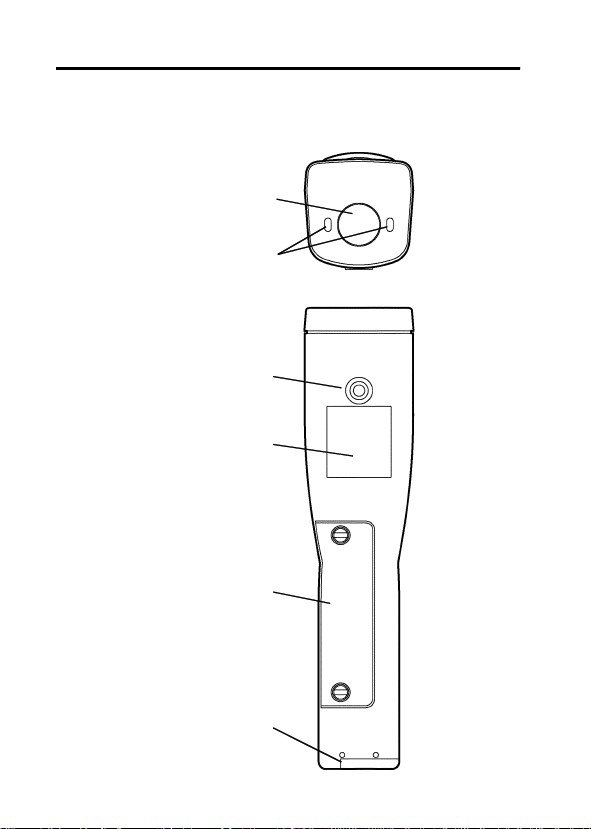
1.2 各部の名称と機能 3444・3445 ラボタイプ
①レンズ
②レーザマーカ照射口
カメラ三脚用ネジ
レーザ説明・警告ラベル
電池ボックス
拡張ボックス用コネクタ
―――――――――――――――――――――――
第1章 概要
Page 11
――――――――――――――――――――――――――
注記 拡張ボックス用コネクタには、オプションの3909 インタ
フェースパック付属の接続ケーブルを接続します。詳し
くは、3909 インタフェースパックの取扱説明書を参照し
てください。
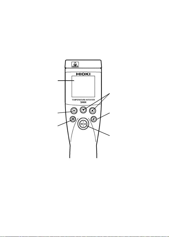
操作部
液晶表示部
④設定値変更キー
7
③モード
切換えキー
⑤OFF キー
―――――――――――――――――――――――
⑦表示分解能
切換えキー
⑥MEAS キー
第1章 概要
Page 12

8
――――――――――――――――――――――――――
①レンズ
測定対象物の赤外線をここより受光します。
②レーザマーカ照射口
ここからレーザマーカが照射されます。
③モード切換えキー
測定中は、上段の瞬時値表示のほか、下段に
値の切換表示ができます。ホールド中は、上記に加えて放射
率、アナログ電圧出力スケールの設定を選択できます。
注記 アナログ電圧出力の使用は、オプションの3909 インタフ
ェースパックが別途必要になります。
④設定値変更キー
放射率およびアナログ電圧出力スケールの設定値の変更に使
用します。
・▼キー :数値が減少
・▲キー :数値が増加
⑤OFF キー
押すと電源が切れます。
⑥MEAS キー
を押すごとに、測定・ホールドが切り換わります。
MEAS
電源オンスイッチはありません。
キーを押すと電源が入ります。ホールド中または
MEAS
マークが表示されている状態にすると、約15秒後に電
SET
源が切れます。(オートパワーオフ)測定中はオートパワーオ
フが働きません。ホールドにしてください。
を切ることもできます。
⑦表示分解能切換えキー
キーを押すごとに、表示分解能1℃・
/
す。
MAX値、MIN
キーで電源
OFF
℃が切り換わりま
0.1
―――――――――――――――――――――――
第1章 概要
Page 13
――――――――――――――――――――――――――
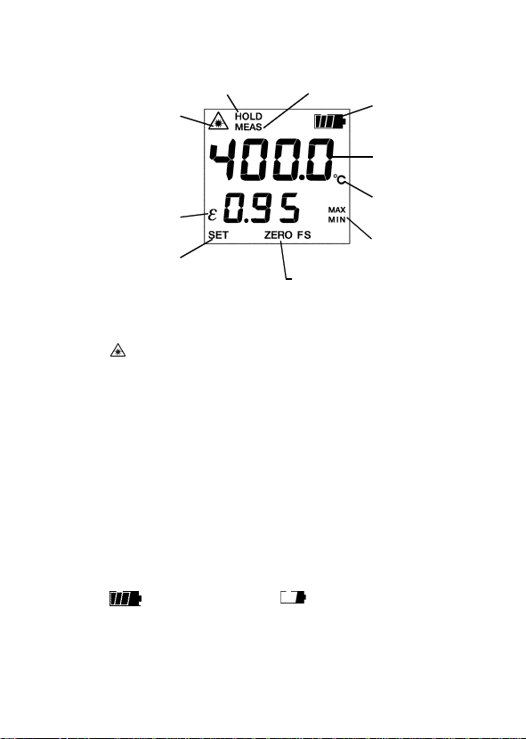
液晶表示部
HOLD マーク
レーザマーク
放射率εマーク
SET マーク
LCD ディスプレイ
・
HOLD :
・
MEAS :
・
・
ε
・
SET
・
ZERO・FS :ZERO
注記 アナログ電圧出力の使用は、オプションの3909 インタフ
ェースパックが別途必要になります。
・
MAX・MIN
・
℃
・
・測定値 :測定温度範囲(
測定値のホールド時に点灯します。
測定中に点滅します。
:点灯 レーザが発光していません。
点滅 レーザが発光しています。
:放射率の表示または設定時に点灯します。
:放射率およびアナログ電圧出力スケール設定
時に点滅します。
アナログ電圧出力スケール下限設定
時に点灯します。
アナログ電圧出力スケール上限設定時
FS
に点灯します。
:
最高温度表示
MAX
最低温度表示
MIN
:摂氏の単位が表示されます。
:電池消耗時は
保証はできませんので、ただちに交換してく
ださい。
と、測定値が点滅します。
MEAS マーク
電池残量マーク
測定値
℃マーク
MAX・MIN
マーク
ZERO・FS マーク
マークが点滅します。確度
-50.0〜500.0
℃)から外れる
9
―――――――――――――――――――――――
第1章 概要
Page 14

10
――――――――――――――――――――――――――
―――――――――――――――――――――――
第1章 概要
Page 15
――――――――――――――――――――――――――
11
第2章 ご使用になる前に
ご使用になる前に以下の作業をしてください。
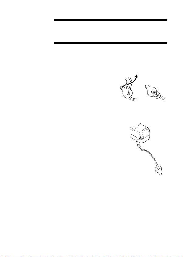
1.付属のネジ回しの取付
紛失防止のため、付属のネジ回しを、
ハンドストラップに取り付けてくだ
さい。
ネジ回しは、電池カバーのネジを外す
時に使います。
2.ハンドストラップの取付
落下防止のため、ご使用前にハンドス
トラップを計器に取り付けてください。
3.電池の装てん
電池を本体裏面の電池ボックスに正しく入れてください。
電池の入れ方は、「
さい。
電池の装てん、交換」を参照してくだ
2.1
―――――――――――――――――――――――
第2章 ご使用になる前に
Page 16
12
――――――――――――――――――――――――――
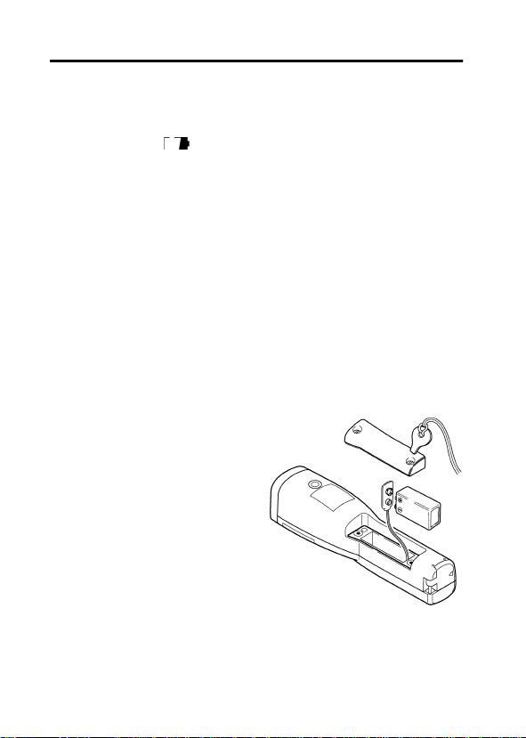
2.1 電池の装てん、交換
・納品時には、計器に電池を取り付けていません。次に示す手
順で電池を取り付けてください。
・電池消耗時は
んので、ただちに交換してください。
・本体がぬれている場合は、必ず水気を拭き取り、隙間に入っ
ている水がケース内に入らないよう、ボックスを下向きにし
て、電池カバーを外してください。
マークが点滅します。確度保証はできませ
使用乾電池:マンガン電池
あるいはアルカリ電池
1.電池カバーを外す。
本体裏面の電池ボックスのネジを付属のネジ回しでゆるめ、
電池カバーを外します。
2.電池を交換する。
古い電池が入っているとき
は、取り外します。
新しい電池の極性(+−)を
確かめ、正しく装着してくだ
さい。
3.電池カバーをしめる。
電池装てん後、電池カバーを
しめ、ネジを均等にしっかり
と締めてください。
―――――――――――――――――――――――
第2章 ご使用になる前に
6F22
6LR61
Page 17
――――――――――――――――――――――――――
電池交換時には、まちがって MEAS キーを押さな
危険
警告
注意
注記
・電池を取り外すと各設定値は失われます。電池交換後は、放
射率やアナログ電圧出力スケールの設定を行ってください。
「
プションのインタフェースパックが必要です。インタフェー
スパックの取扱説明書を参照してください。
・長い間使用しないときは、電池の液漏れによる腐食を防ぐた
めに電池を抜いて保管してください。
・付属品の電池はモニター用ですので、寿命が短い時がありま
す。
いでください。レーザマーカが目に入ることがあ
りますので危険です。また交換後は必ずふたをし
てから使用してください。
・電池交換するときは、極性+、−に注意し逆挿入
しないように電池を入れてください。
・使用済の電池をショート、分解または火の中に
投入しないでください。破裂する恐れがあり、
危険です。
・使用済の電池は指定された場所に種別に従って
処分してください。
・ケーブルを電池カバーに挟み込まないように注
意してください。
・ゴムパッキンにゴミが着いていたり、よじれた
状態で電池カバーを閉めないでください。計器
本体の防滴構造が保たれません。
放射率の設定方法」参照。アナログ電圧出力の使用はオ
3.3
13
―――――――――――――――――――――――
第2章 ご使用になる前に
Page 18

14
――――――――――――――――――――――――――
―――――――――――――――――――――――
第2章 ご使用になる前に
Page 19
――――――――――――――――――――――――――
15
第3章 測定方法
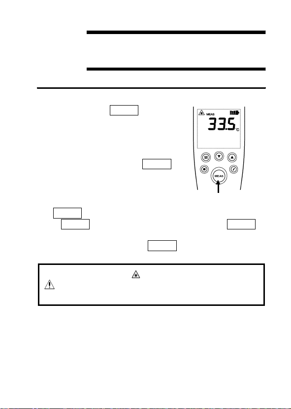
3.1 測定の開始・終了
電源オフのとき
1.
すと電源が入ります。
ディスプレイには、前回、電
LCD
源が切れる直前の画面が表示さ
れます。
電源オフの状態から
注記
キーを1秒以上押し続けると
測定を開始します。
レンズを測定対象物に向けます。
2.
3. MEAS
MEAS
ーを押している間はレーザマーカが発光し、対象物に照準を
合わせることができます。
カは消灯しますが、測定は継続して行われます。
キーを押します。
キーを押している間測定を行います。
MEAS
キーを押
MEAS
MEAS
MEAS
キーを離すとレーザマー
キ
3444・3445 で
危険
発光しています。レーザマーカが目(目に障害)に
入らないように注意してください。
―――――――――――――――――――――――
マーク点滅中は、レーザマーカを
第3章 測定方法
Page 20
16
――――――――――――――――――――――――――
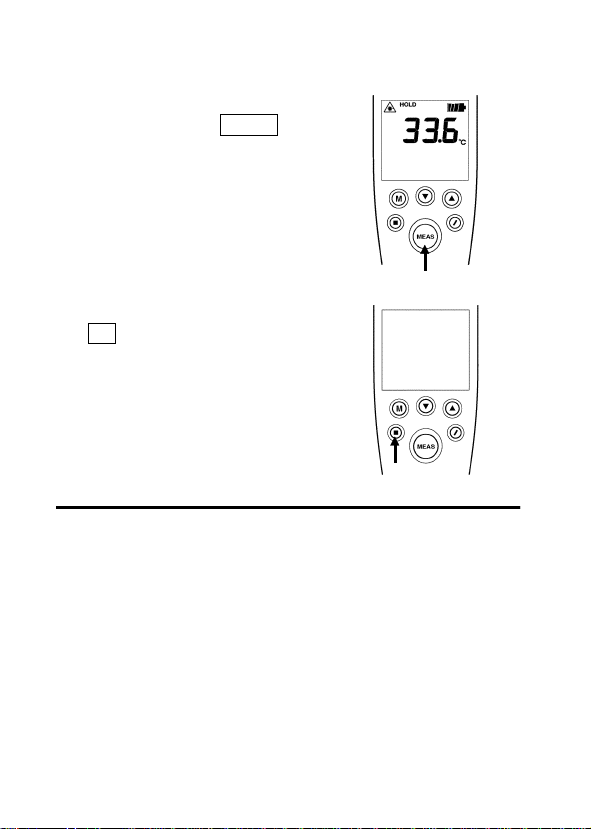
表示部を読みます。
4.
測定を終了します。
5.
測定中にもう一度
押すと、測定を終了し、その時の
測定値がホールドされます。
注記
・測定値が測定温度範囲(
℃)から外れると表示が点
500.0
滅します。
電源を切ります。
6.
キーを押すと、電源が切れま
■
す。
オートパワーオフが働き、電源が
切れます。
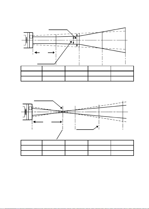
3.2 測定視野と照準 注記
・測定視野は光学応答
は測定径よりも十分大きいことが必要です(
・レーザマーカは測定距離
ドに照射されます。
・測定距離は、2m以上離れていても、測定対象物からの赤外
線を吸収したり、さえぎる物がない限り、温度は測定視野の
平均値として表示されます。
点灯中は、約15秒後に
HOLD
キーを
MEAS
〜
-50.0
の測定径です。測定対象物の大きさ
90%
mまでは、測定視野径の両サイ
1.5
1.5〜2
倍以上)。
―――――――――――――――――――――――
第3章 測定方法
Page 21
――――――――――――――――――――――――――
3444
照準ピッチ
距離
測定視野
距 離 0.5 m 1m 1.5 m 2m
測定視野
照準ピッチ
3445
照準ピッチ
φ20 mm φ24 mm φ48 mm φ80 mm
34 mm 41 mm 48 mm 55 mm
17
距離
距 離 73 mm 100 mm 150 mm 200 mm
測定視野
照準ピッチ
φ2.0±1mm φ8 mm φ20 mm φ33 mm
0mm 10 mm 28 mm 47 mm
―――――――――――――――――――――――
測定視野
第3章 測定方法
Page 22
18
――――――――――――――――――――――――――
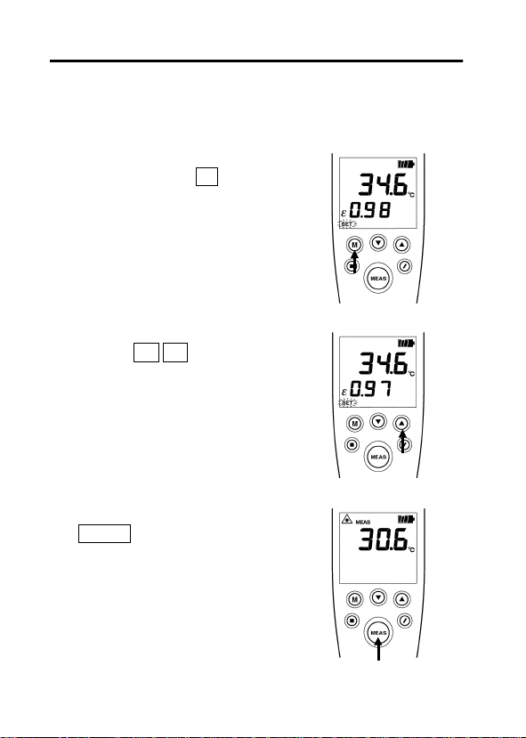
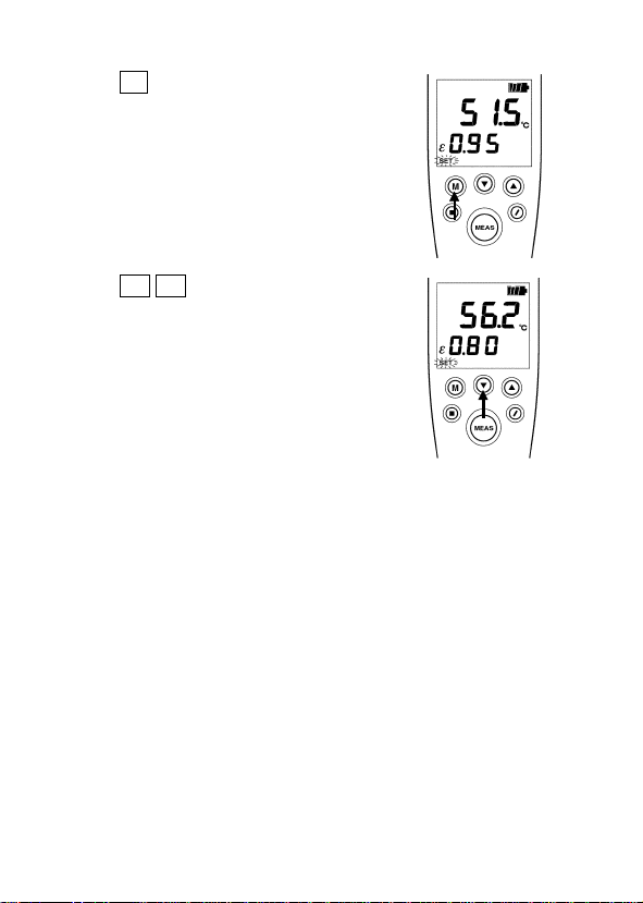
3.3 放射率の設定方法
物体はそれぞれ固有の放射率を持っています。正しい温度を
求めるため、放射率を測定対象物の値に設定してください。
初期値は
1. ε(放射率)を表示する。
HOLD
押し放射率を表示させます。εが
点灯し、
ε(放射率)を変更する。
2.
数字は、
ます。
3. ε(放射率)の設定を終了する。
MEAS
直ちに測定できます。
に設定されています。
0.95
の状態から
が点滅します。
SET
▲
▼
キーを押すと設定終了し、
キーを数回
M
キーで変更でき
―――――――――――――――――――――――
第3章 測定方法
Page 23
――――――――――――――――――――――――――
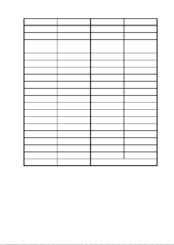
品名 放射率 品名 放射率
アスファルト
コンクリート
セメント
砂
土
水
氷
雪
ガラス
セラミック
大理石
ほたる石
石膏
しっくい
れんが(赤色
繊維
布(黒色
)
人の皮膚
なめし皮
放射率(ε)は測定対象物の表面の状態や色により多少異
注記
なります。温度を正確に測定したい場合や、放射率のわ
からないものの温度を測定したいときは、別売りの黒体
テープ、黒体スプレーを使用してください。
放射率(ε)は黒体テープ、黒体スプレーに示されている
値に設定してください。
0.90〜0.98
0.94
0.96
0.90
0.92〜0.96
0.92〜0.96
0.96〜0.98
0.83 Al
0.90〜0.95 Cr
0.90〜0.94 Cu
0.94 Fe
0.30〜0.40 Ni
0.80〜0.90 Ti
0.89〜0.91 Zn
0.93〜0.96
)
0.90
0.98
0.98
0.75〜0.80
木炭(粉
)
塗装ラッカー
塗装ラッカー
艶消し黒
(
ゴム(黒
プラスチック
材木
紙
真鍮酸化物
青銅凹凸面
圧延ステンレス鋼
赤くさびた鉄
)
)
酸化物
酸化物
酸化物
酸化物
酸化物
酸化物
酸化物
0.96
0.80〜0.95
0.97
0.94
0.85
0.90
0.70〜0.94
0.76
0.81
0.78
0.78〜0.82
0.90
0.40〜0.60
0.11〜0.28
0.56〜0.64
0.55
0.45
0.69
19
―――――――――――――――――――――――
第3章 測定方法
Page 24
20
――――――――――――――――――――――――――
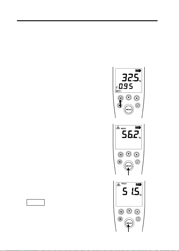
3.4 放射率(ε)の簡易的な求め方
測定対象物の放射率が不明である場合、オプションの黒体テ
ープを用いて簡易的に求めることができます。
測定対象物に、黒体テープを貼り、適度に加熱(室温+20℃
1.
以上)して、できるだけ一定温度に保ちます。
(温度が高い方が、放射率は正確に求められます)
本器のεの値を黒体テープの放
2.
射率(
黒体テープを貼った部分の温度
3.
を本器で測定して、記録しておき
ますます。(6.で使います)
次に黒体テープを貼っていない
4.
部分で、3で測定した部分にでき
るだけ近い部分を測定し、
MEAS
HOLD
)に設定します。
0.95
キーを離して測定値を
します。
―――――――――――――――――――――――
第3章 測定方法
Page 25
――――――――――――――――――――――――――
キーを数回押して、放射率設
5. M
定画面にします。
21
6. ▼
で求めた値になるまでεの値を
変化させます。この時のεの値
が、測定対象物の放射率になりま
す。
注記
―――――――――――――――――――――――
キーを押して、温度が
▲
黒体テープの替わりに、オプションの黒体スプレーを用
いても同様の方法で対象物の放射率を求めることができ
ます。この場合、2のεの値を黒体スプレーのラベルに記
載の値に設定してください。
3
第3章 測定方法
Page 26
22
――――――――――――――――――――――――――
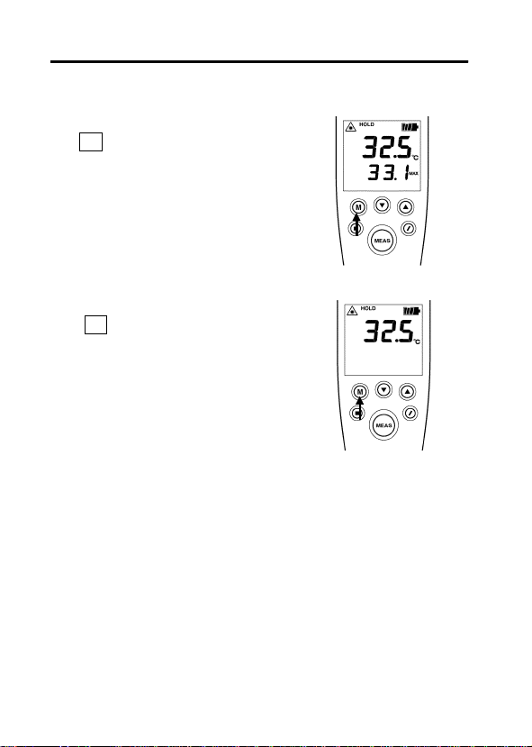
3.5 最高(最低)温度を表示する
① MAX/MIN を表示する。
キーを押すと
M
に最高(最低)温度を表示します。
ホールド時は、前回の測定の最高
(最低)温度を表示します。
測定中は、測定中の最高(最低)
温度を表示します。
② MAX/MINの表示を解除する。
キーを数回押して、なにも表
M
示されない状態にしてください。
MAX→MIN
の順
―――――――――――――――――――――――
第3章 測定方法
Page 27

――――――――――――――――――――――――――
3.6 パソコンを利用する場合
オプションの
よりリアルタイムでパソコンにデータを取り込み処理するこ
とができます。
インタフェースパック
3909
モジュラケーブル、拡張ボックス、
ソコン取り込みソフト)、アナログ出力ケーブル
1. 3444・3445を3909
用クロスケーブル(別売品)を使用してパーソナルコン
232C
ピュータと接続します。
2. 3909のTEMP
てください。
・リアルタイムのデータ取り込みが可能です。データは表とグ
ラフに表示することができ、簡単にデータ管理を行うことが
できます。
・
に取り込むことも可能です。
Excel*
インタフェースパックを使用することに
3909
ユーティリティ(パ
TEMP
のモジュラケーブル、拡張ボックスと
ユーティリティ(取り込みソフト)を起動し
23
RS-
* Excel
―――――――――――――――――――――――
は、米国マイクロソフト社の登録商標です。
第3章 測定方法
Page 28

24
――――――――――――――――――――――――――
―――――――――――――――――――――――
第3章 測定方法
Page 29

――――――――――――――――――――――――――
25
第4章 仕様
形式
検出素子/光
学レンズ
測定波長
測定温度範囲
表示分解能
確度保証期間
測定精度
200.1〜500.0℃
0.0〜200.0℃
‑50.0〜‑0.1℃
再現性
応答時間
測定視野
照準
3444・3445放射温度ハイテスタ(ラボタイプ)
サーモパイル/シリコン
8〜16μm
−50.0℃〜500.0℃
0.1℃/1℃
1年間
(バッテリマーク点滅時を除く)
±1% rdg.
±2℃
±10%rdg.+2℃
ε=1.00、ケース温度23±5℃、
周囲湿度55%rh
0.1℃分解能
±0.5℃(0.0〜500.0℃)
±1℃(‑50.0〜‑0.1℃)
1℃分解能
±1℃(0〜500℃)
±2℃(‑50〜‑1℃)
0.1℃分解能
1.6秒以下(95%応答)
1℃分解能
0.7秒以下(95%応答)
3444 φ24±3/1000 mm (90%エネルギリミット)
3445 φ2.5±1/73 mm ( 〃 )
2ビームレーザマーカ(クラス2)
―――――――――――――――――――――――
第4章 仕様
Page 30

26
――――――――――――――――――――――――――
放射率補正
オートパワー
オフ
サンプリング
レート
その他の機能
電源
最大定格電力
電池寿命
使用温湿度範
囲
保存温湿度範
囲
使用場所
外形寸法
質量
防じん性・
防水性
適合規格
付属品
オプション
:アナログ電圧出力および
*1
用はオプションのインタフェースパックが必要です。
*2:IP54
―――――――――――――――――――――――
第4章 仕様
0.10〜1.00
約15秒(ホールドまたは設定時)
1.25回/秒
最大値または最小値表示、アナログ電圧出力
(0〜1 V)、RS‑232Cインタフェース*1
定格電源電圧 DC9 V×1
積層形マンガン乾電池
(6F22×1または6LR61×1)
252 mVA(MAX)
照準点灯時連続使用約20時間(アルカリ電池
使用)
0〜40℃、35〜85%rh(結露なきこと)
−20〜55℃(結露なきこと)
高度2000 mまで、屋内
約47 W×200 H×48 D mm
約280g
IP54 *2
EN61326
取扱説明書、防滴ケース、ハンドストラッ
プ、積層形マンガン乾電池(6F22)、ネジ回し
(電池カバー取り外し用)
3909インタフェースパック、黒体スプレー、
黒体テープ、ACアダプタ(AC‑10)
RS-232C
いかなる方向からの水の飛沫を受けても有害な
影響のないもの(
IEC529(1989)
インタフェースの使
)
Page 31

――――――――――――――――――――――――――
27
第5章 保守・サービス
本器の保護機能が破損している場合は、使用でき
警告
注意
ないように廃棄するか、知らないで動作させるこ
とのないように、表示しておいてください。
・本器の汚れをとるときは、柔らかい布に水か中
性洗剤を少量含ませて、軽くふいてください。ベ
ンジン、アルコール、アセトン、エーテル、ケト
ン、シンナー、ガソリン系を含む洗剤は絶対に使
用しないでください。変形、変色することがあり
ます。
・長い間使用しないときは、電池の液漏れによる
腐食を防ぐために電池を抜いて保管してくださ
い。
・故障と思われるときは、電池の消耗、プローブ部
の接続を確認してから、お買上店(代理店)か最
寄りの営業所にご連絡ください。輸送中に破損
しないように梱包し、故障内容も書き添えてく
ださい。輸送中の破損については保証しかねま
す。
・レンズが汚れているときは、カメラのレンズを
掃除するブロアなどを使ってレンズのホコリを
取り除いてください。
・汚れがひどい時は、綿棒にアルコールを少量含
ませて拭き取ってください。
―――――――――――――――――――――――
第5章 保守・サービス
Page 32

28
――――――――――――――――――――――――――
5.1 故障かなと思ったら
症 状 原 因 対 策
表示がでない電池切れまたは入れ間違い電池を交換または正し
く入れ直してください
測定値がお
かしい
℃が点滅する。使用周囲温度範囲(0〜
が表示
Err
される
レンズが汚れている レンズを清掃してくだ
さい
近くに高温物体などの
熱源がある
放射率の値が適切でない放射率を適切な値にし
℃)から外れている
40
検出器故障
Err0:
校正定数エラー
Err1:
測定回路エラー
Err2:
ソフトエラー
Err3:
温度センサエラ
ErrH:
ー(高温
)
温度センサエラ
ErrL:
ー(低温
)
不揮発性メモリ
Err-:
エラー
バックアップエ
Errb:
ラー
しゃへい板等で熱源を
遮断してください
てください
対象物から離れて測定
してください。
電池を新品に交換して
ください。
電池交換後もエラー表
示が消えない場合は、
故障している可能性が
あります。お買上店
代理店)か最寄りの営
(
業所にご連絡下さい。
○サービス
対策後も上記の症状が直らない場合は、故障している可能性
があります。お買上店(代理店)か最寄りの営業所にご連絡
ください。
―――――――――――――――――――――――
第5章 保守・サービス
Page 33

――――――――――――――――――――――――――
5.2 測定のアドバイス
Q:ガラス越しに温度を測定したい
A:一般のガラスは、本器で測定している波長(8〜16μm)
の赤外線を吸収してしまいます。したがって、本器では
ガラスの向こうにある物体の温度を計ることはできず、
ガラス自体の温度を測定していることになります。
Q:光があたっている物体の温度を測定したい
A:蛍光灯は赤外線をほとんど照射しませんので、通常の測
定にはほとんど影響ありません。
しかし、太陽光や白熱電球は本器で測定している波長の
赤外線を照射していますので、測定誤差が大きくなる可
能性があります。
Q:気体や炎の温度を測定したい
A:気体や炎は赤外線を透過しますので、気体や炎そのもの
の温度は測定できません。
Q:雨や霧を通して測定したい
A:雨や霧は赤外線を反射、吸収してしまいますので、正確
な測定はできません。
Q:測定する距離によって測定値は変わらないか
A:本器で測定している波長(8〜16μm)の赤外線は、空気
にはほとんど吸収されません。したがって、測定距離に
関係なく正確な測定ができます。
29
―――――――――――――――――――――――
第5章 保守・サービス
Page 34

30
――――――――――――――――――――――――――
―――――――――――――――――――――――
第5章 保守・サービス
Page 35

保 証 書
形名
3444・3445
本製品は、弊社の厳密なる検査を経て合格した製品をお届けした物です。
万一ご使用中に故障が発生した場合は、お買い求め先にご連絡ください。
本書の記載内容で無償修理をさせていただきます。また、製品の使用による損失について
は、購入金額までの支払いとさせていただきます。なお、保証期間は購入日より3年間で
す。購入日が不明の場合は、製品の製造月から3年を目安とします。ご連絡の際は、本書
を提示してください。また、確度については、明示された確度保証期間によります。
お客様 ご住所: 〒
*お客様へのお願い
・保証書の再発行はいたしませんので、大切に保管してください。
・「形名、製造番号、購入日」およびお客様「ご住所、ご芳名」は恐れ入りますが、お
客様にて記入していただきますようお願いいたします。
1.取扱説明書・本体注意ラベル(刻印を含む)などの注意事項にしたがった正常な使用
状態で保証期間内に故障した場合には、無償修理いたします。また、製造後一定期間
を経過したものおよび部品の生産中止、不測の事態の発生などにより修理不可能と
なった場合は、修理、校正などを辞退する場合がございます
2.保証期間内でも、次の場合には保証の対象外とさせていただきます。
−1.製品を使用した結果生じる被測定物の、二次的、三次的な損傷、被害
−2.製品の測定結果がもたらす二次的、三次的な損傷、被害
−3.取扱説明書に基づかない不適当な取り扱い、または使用による故障
−4.弊社以外による不当な修理や改造による故障および損傷
−5.取扱説明書に明示されたものを含む、部品の消耗
−6.お買い上げ後の輸送、落下などによる故障および損傷
−7.外観上の変化(筐体のキズなど)
−8.火災、風水害、地震、落雷、電源異常(電圧、周波数など)、戦争・暴動行為、
−9.保証書の提出が無い場合
−10.その他弊社の責任とみなされない故障
−11.特殊な用途(宇宙用機器、航空用機器、原子力用機器、生命に関わる医療用
3.本保証書は日本国内のみ有効です。(
サービス記録
年月日 サービス内容
製造番号 保証期間
ご芳名:
放射能汚染およびその他天災地変などの不可抗力による故障および損傷
機器及び車輌制御機器など)に組み込んで使用する場合で、前もってその旨
を連絡いただかない場合
購入日 年 月より3年間
This warranty is valid only in Japan.)
386-1192
〒
TEL 0268-28-0555
FAX 0268-28-0559
長野県上田市小泉81
06-03
Page 36

外国主要販売ネットワーク
外国代理店については
ご覧いただくか、最寄りの営業所または本社
販売企画課までお問い合わせください。
URL http: //www.hioki.com/
HIOKI USA CORPORATION
6 Corporate Drive, Cranbury, NJ 08512 USA
TEL +1-609-409-9109
FAX +1-609-409-9108
E-MAIL hioki@hiokiusa.com
HIOKI
ホームページを
Page 37

HIOKI 3444・3445 放射温度ハイテスタ
取扱説明書
発行年月
編集 ・ 発行 日置電機株式会社
問合せ先 日置電機株式会社
TEL: 0268-28-0560
FAX: 0268-28-0579
E-mail: info@hioki.co.jp
URL http: //www.hioki.co.jp/
2008年9
開発支援課
販売企画課
〒
月 改訂5版
386-1192
0120-72-0560
長野県上田市小泉
81
Pri nt e d in J a p an 3444A980-05
・本書の内容に関しては万全を期していますが、ご不明な
点や誤りなどお気づきのことがありましたら、本社 販売
企画課または最寄りの営業所までご連絡ください。
・本書は改善のため予告なしに記載事項を変更すること
があります。
・本書には著作権によって保護 され る内容 が含 まれま す。
本書の内容を弊社に無断で転載、複製、改変することは
禁止されています。
Page 38

Page 39

3444/3445
TEMPERATURE
HiTESTER
INSTRUCTION MANUAL
Page 40

Page 41

Contents
Introduction
Safety Notes
Inspection
Notes on Use
Chapter 1 Summary
1.1 Product Summary 1
1.2 Names and Functions of Parts
Chapter 2 Prior to Use 9
2.1 Battery Loading and Replacement 10
Chapter 3 Making Measurements 13
3.1 Start and Complete Measurement 13
3.2 Target Size and Sighting
3.3 Setting Emissivity (ε)
3.4 Simple Method to Determine ε
3.5 Displaying MAX (MIN) Temperature
3.6 Using the Temperature HiTester
with a Personal Computer
15
16
18
21
22
Chapter 4 Specification 23
Chapter 5 Maintenance and Service
5.1 Troubleshooting 27
5.2 Questions and Answers
about Measurement
25
28
i
ii
iv
v
1
3
Page 42

Page 43

―――――――――――――――――――――――――――
Introduction
Thank you for purchasing this Hioki "3444/3445
Temperature HiTester." To get the maximum
performance from the instrument, please read this
manual first, and keep this at hand.
i
――――――――――――――――――――――――
Introduction
Page 44

ii
―――――――――――――――――――――――――――
Safety Notes
WARNING
Incorrect measurement procedures could result in
injury or death, as well as damage to the
equipment. Please read this manual carefully and
be sure that you understand its contents before
using the equipment. The manufacturer disclaims
all responsibility for any accident or injury except
that resulting due to defect in its instrument.
This Instruction Manual provides information and
warnings essential for operating this equipment in a
safe manner and for maintaining it in safe operating
condition. Before using this equipment, be sure to
carefully read the following safety notes.
Safety symbols
In the manual, this mark indicates
explanations which it is particularly
important that the user read before using
the instrument.
Indicates warnings relating to the laser.
――――――――――――――――――――――――
Safety Notes
Page 45

―――――――――――――――――――――――――――
iii
The following symbols are used in this Instruction
Manual to indicate the relative importance of
cautions and warnings.
Indicates that incorrect operation
DANGER
presents extreme danger of accident
resulting in death or serious injury to
the user.
Indicates that incorrect operation
WARNING
presents significant danger of accident
resulting in death or serious injury to
the user.
Indicates that incorrect operation
CAUTION
presents possibility of injury to the user
or damage to the equipment.
Denotes items of advice related to
NOTE
performance of the equipment or to its
correct operation.
Accuracy
・
rdg. (displayed or indicated value)
This signifies the value actually being measured,
i.e., the value that is currently indicated or displayed
by the measuring instrument.
――――――――――――――――――――――――
Safety Notes
Page 46

iv
―――――――――――――――――――――――――――
Check before use
・
Before using the instrument, inspect it and check
the operation to make sure that the instrument was
not damaged due to poor storage or transport
conditions. If damage is found, contact your dealer
or Hioki representative.
Inspection
When you receive this instrument, before use, please
check that no abnormality or damage has occurred
during delivery. In particular, be sure to check the
accessories, the liquid crystal display, the control
keys, and the lens.
In the unlikely event of damage, or if the instrument
does not function according to specification, you
should immediately contact the dealer from whom
you bought the instrument, or the nearest Hioki
service facility.
――――――――――――――――――――――――
Inspection
Page 47

―――――――――――――――――――――――――――
Notes on Use
In order to ensure safe operation and to obtain
maximum performance from the instrument, observe
the cautions listed below.
DANGER
Operation of this instrument according to any
・
procedure not specified in this manual may
cause explosion due to dangerous laser
radiation.
The 3444/3445 (Laboratory type instrument) uses
・
as a light source a semiconducting laser which
emits visible light, and which conforms to JIS
standard class 2 (JIS C6802). (Wavelength
670nm, maximum power output 1 mW)
Since there is considerable danger of this laser
light causing damage to the eyes, be very
careful not to direct this laser light into your
eyes or those of another person.
Do not look directly into the laser light from the
・
optical system.
When measuring the temperature of an object
・
which has a mirror finish, be careful not to allow
the laser light beam to be reflected off the
surface into your eyes or those of another
person.
Do not allow the laser light beam to impinge
・
upon any gas which can explode.
v
――――――――――――――――――――――――
Notes on Use
Page 48

vi
―――――――――――――――――――――――――――
WARNING
To prevent electric shock, do not allow the
・
instrument to become wet and do not use the
instrument when your hands are wet.
Ensure that protective functions are fail-safe:
・
that is to say, that if they fail they either prevent
the instrument from operating or give an
indication to prevent unwitting operation.
CAUTION
Do not use the instrument near any device which
・
generates strong electromagnetic radiation or near
a static electrical charge, as these may cause
errors.
The instrument should always be operated indoors
・
in a range from 0
to 40 and 35% to 85% RH or
less. Do not use the instrument in direct sunlight,
dusty conditions, or in the presence of corrosive
gases.
Do not store or use the instrument where it will be
・
exposed to direct sunlight, high temperatures, high
humidity, or condensation. If exposed to such
conditions, the instrument may be damaged, the
insulation may deteriorate, and the instrument may
no longer satisfy its specifications.
――――――――――――――――――――――――
Notes on Use
Page 49

―――――――――――――――――――――――――――
CAUTION
This instrument has been constructed with some
・
vii
degree of water resistance, but if it is subjected to
direct contact with water for a long period of time,
water may get into the instrument. Further, water
drops left on the lens will cause measurement
errors. Wipe off any water drops promptly.
Do not use the instrument where it may be exposed
・
to corrosive or explosive gases. The instrument
may be damaged, or explosion may occur.
To avoid damage to the instrument, do not subject
・
the equipment to vibrations or shocks during
transport or handling. Be especially careful to avoid
dropping the equipment.
Do not point the lens at the sun or at any other
・
source of strong light. If you do, the sensor may be
damaged.
Do not contact the lens against the object whose
・
temperature is to be measured, or get it dirty, allow
it to be scratched, or allow any foreign material to
adhere to it. Doing so may cause errors.
・ Before use, verify that no damage has occurred due
NOTE
to careless storage or transport, and check the
appearance and operation of the instrument.
・ The
indicator flashes when the remaining
battery capacity is low. In this case, the instrument's
reliability is not guaranteed. Replace the battery
immediately.
――――――――――――――――――――――――
Notes on Use
Page 50

viii
―――――――――――――――――――――――――――
――――――――――――――――――――――――
Notes on Use
Page 51

―――――――――――――――――――――――――――
Chapter 1
Summary
1.1 Product Summary
1. Theory of Measurement
Every object emits infrared energy in accordance
with its temperature. By measuring the amount of
this radiant energy, it is possible to determine the
temperature of the emitting object.
2. About infrared
Infrared radiation is a form of light (electromagnetic
radiation), and has the property that it passes easily
through air, while it is easily absorbed by solid
matter.
With an emission thermometer which operates by
detecting infrared radiation, accurate measurement is
possible, irrespective of the air temperature or the
measurement distance.
1
3. Emission Thermometer Structure
Infrared radiation which has been emitted from the
object is focused upon an infrared radiation sensor,
via an optical system which includes a lens which is
transparent to infrared radiation, an 8 μm cuton
filter, etc..
――――――――――――――――――――――――
Chapter 1 Summary
Page 52

2
―――――――――――――――――――――――――――
The output signal from the infrared radiation sensor
is input to an electronic circui t along with the
output signal from a standard temperature sensor.
The electronic circuit calculates the object
temperature while applying standard temperature
compensation, thermal emissivity compensation,
etc., and displays the result.
――――――――――――――――――――――――
Chapter 1 Summary
Page 53

―――――――――――――――――――――――――――
1.2 Names and Functions of Parts
3444/3445 laboratory type unit
(1)Lens
(2)Laser port
Screw hole for camera tripod
Laser specification (spec.)
and caution label
Battery box
3
Connector cover
(inside: connector
for interface pack)
――――――――――――――――――――――――
Chapter 1 Summary
Page 54

4
―――――――――――――――――――――――――――
・ Connect the cable provided with the optional 3909
NOTE
Interface Pack to the expansion box connector. For
details, please refer to the user instructions provided
with the 3909 Interface Pack.
Operating section
LCD display
(4)Parameter adjust
keys
(3)Mode select
key
(5)OFF key
(6)Displayed
resolution select
key
(5)Measure key
(1) Lens
Infrared rays from the object whose temperature is
to be measured are received here.
(2) Laser marker beam emission openings
The laser marker beams are emitted from here.
(3) Mode select key
This key displays the
MAX/MIN
-temperature or the
present high and low readings during measurement.
In addition, emissivity and analog voltage output
scale are also displayable when on
――――――――――――――――――――――――
Chapter 1 Summary
HOLD
.
Page 55

―――――――――――――――――――――――――――
・ To use the analog voltage output function, an
NOTE
optional interface pack is required.
(4) Parameter adjust keys
These keys raise/lower emissivity and analog voltage
output scale.
・
key: Decreases
・
key: Increases
If either of these Parameter adjust keys is held
down, the numerical value changes rapidly in the
appropriate direction.
(5) OFF key
Pressing this key turns OFF the power.
(6)
key
MEAS
Every time the
key is pressed, the
MEAS
thermometer toggles between the measurement or
hold functions.
There is no power switch.
Pressing the
key turns ON the power. The
MEAS
power cuts OFF 15 seconds after HOLD or SET is
displayed (automatic power OFF).
The automatic power OFF function does not work
during measurement. Select HOLD.Powercanalso
be turned off with the
key.
(7) Displayed resolution select key
Every time the
resolution, 1
key is pressed, the displayed
/
or 0.1 , is selected.
5
――――――――――――――――――――――――
Chapter 1 Summary
Page 56

6
―――――――――――――――――――――――――――
LCD display
HOLD indicator
Laser indicator
MEAS indicator
Battery indicator
Measured value
Emissivity
indicator
SET indicator
ZERO/FS indicator
LCD display
・
indicator : Displayed when the measured
HOLD
value is displayed.
・MEAS indicator : Displayed when measurement
is being carried out.
・Laser indicator : Displayed when laser is not
emitted.
Blinks when laser is being
emitted.
・ε indicator : Displayed when emissivity is being
set and displayed.
・
indicator : Blinks when emissivity and
SET
analog voltage output scale are
being set.
・
ZERO/FS
ZERO
indicator
: Displayed when lower limit of analog
voltage output scale is being set.
F.S. : Displayed when upper limit of analog
voltage output scale is being set.
indicator
MAX/MIN
indicator
――――――――――――――――――――――――
Chapter 1 Summary
Page 57

―――――――――――――――――――――――――――
・ To use the analog voltage output function, an
NOTE
optional interface pack is required.
・MAX/MIN indicator
MAX : max. temp. display
: min. temp. display
MIN
・ indicator : Unit of centigrade.
・
indicator : The indicator flashes
when the remaining battery
capacity is low. In this case, the
instrument's reliability is not
guaranteed. Replace the battery
immediately.
・Measured value : The entire display blinks when
the measurement value falls
outside the measurement range
(-50.0 to 500.0
).
7
――――――――――――――――――――――――
Chapter 1 Summary
Page 58

8
―――――――――――――――――――――――――――
――――――――――――――――――――――――
Chapter 1 Summary
Page 59

―――――――――――――――――――――――――――
Chapter 2
Prior to Use
Prior to operating the thermometer, carry out the
following:
1. Attaching the accessory screwdriver
Attach the accessory
screwdriver to the hand strap
so that it will not get lost.
This screwdriver is used to
remove the battery cover screws.
Attaching the screwdriver
2. Attaching the hand strap
Attach the hand strap to the
instrument to help prevent its
being dropped.
3. Loading the battery
Place the battery correctly in
the battery box at the back of
main body.
For loading the battery, refer to "2.1 Battery
Loading and Replacement".
9
――――――――――――――――――――――――
Chapter 2 Prior to Use
Page 60

10
―――――――――――――――――――――――――――
2.1 Battery Loading and Replacement
・ The thermometer does not come with the battery
loaded. Load the battery according to the procedure
described below.
・ The
battery capacity is low. In this case, the instrument's
reliability is not guaranteed. Replace the battery
immediately.
・ If the main body is wet, be sure to wipe off the
water, set the battery box facing downward so that
any water in the joint will not enter the case, and
then remove the battery cover.
Dry battery used : Manganese battery 6F22 or alkali
1. Remove the battery cover.
Loosen the screws of
the battery cover at the
back of the main body
with the accessory
screwdriver and
remove the battery
cover.
2. Replace the battery.
Remove the old
battery.
Check the polarity (+ or -) of the new battery, and
load it correctly.
3. Close the battery cover.
After the battery is loaded, close the battery cover,
and tighten the screws evenly and firmly.
――――――――――――――――――――――――
Chapter 2 Prior to Use
indicator flashes when the remaining
battery 6LR61
rubber gasket
Page 61

―――――――――――――――――――――――――――
DANGER
11
When changing the battery, be careful not to
press the
MEAS
key by mistake.
It is very dangerous to allow the laser beam to
shine into your eyes or those of another person.
Also, after changing the battery, be sure to close
the cover before using the unit.
WARNING
When changing the battery, be sure to fit the
・
battery the proper way around (i.e. with the
correct polarity).
Do not short circuit the old exhausted battery or
・
throw them into a fire; they might explode.
Dispose of the old exhausted battery in an
・
approved waste disposal facility.
CAUTION
Take care not to get the wire caught in the battery
・
cover.
Do not close the battery cover if the rubber gasket
・
is dirty or twisted. Otherwise, the water-resistance
of the instruments main body will not be maintained.
――――――――――――――――――――――――
Chapter 2 Prior to Use
Page 62

12
―――――――――――――――――――――――――――
・ When the battery is removed, various set values are
NOTE
lost. When replacing the battery, set the emissivity
and analog voltage output scale. (Refer to "3.3
Setting Emissivity (ε)". To use the analog voltage
output function, an optional interface pack is
required. Refer to the instruction manual for more
information about this interface pack.)
・ When not in use for a long time, to prevent possible
corrosion caused by battery leakage, remove the
battery before storage.
・ The battery included with 3444/3445 have a short
time.
――――――――――――――――――――――――
Chapter 2 Prior to Use
Page 63

―――――――――――――――――――――――――――
13
Chapter 3
Making
Measurements
3.1 Start and Complete Measurement
1. When the power is off,
pressing the
turns on the power.
The values and settings on
the LCD display return to
the state before the power
was last turned off.
MEAS
key
・ If, from the power off condition, the
NOTE
――――――――――――――――――――――――
held down for more than one second, measurement
starts.
2. Point the lens at the object whose temperature is to
be measured.
3. Press the
Measurement is performed as long as the
is kept pressed. While the
pressed, the laser sighting beam is emitted so you
can aim it at the object.
Releasing the
even measurement is continued.
MEAS
key.
key is being
MEAS
key turns off the laser indicator
MEAS
Chapter 3 Making Measurements
MEAS
key is
MEAS
key
Page 64

14
―――――――――――――――――――――――――――
DANGER
With the 3444/3445, whenever the indication is
flashing, the laser marker beam is being emitted.
Exercise extreme care not to allow the laser
marker beam to enter your eyes (because of this
laser light causing damage to the eyes) or those
of another person.
4. Read the display.
5. Complete measurement.
When the
MEAS
key is
pressed again during
measurement,
measurement is completed,
and the measured value is
saved (HOLD).
・ When the measurement value is out of the
NOTE
measurement temperature range (-50.0 to 500.0
),
the display will flash.
6. Turn OFF power.
Pressing the
key turns
OFF the power.
While
HOLD
is lit, the
automatic power OFF
function works after
approx. 15 seconds to turn
OFF the power.
――――――――――――――――――――――――
Chapter 3 Making Measurements
Page 65

―――――――――――――――――――――――――――
15
3.2 Target Size and Sighting
・ Although the field of measurement and the sighting
NOTE
3444
almost coincide, actually the field of measurement
corresponds to the diameter for 90% optical
response. The object whose temperature is to be
measured needs to be larger than the measurement
diameter by an adequate margin‐at least 1.5 to 2
times larger.
・ The sighting beam must encompass the area to be
measured up to the max. measurement distance of
1.5 meters.
・ Even if the measurement distance is greater than 2
meters, temperature is displayed as a mean value of
the target size if there is no substance to absorb or
interrupt the infrared ray from the object being
measured.
Sighting pitch
Distance
Target size
distance 0.5 m 1m 1.5 m 2m
20 mm
Target size
Sighting
pitch
φ
34 mm 41 mm 48 mm 55 mm
――――――――――――――――――――――――
24 mm
φ
Chapter 3 Making Measurements
48mm
φ
80 mm
φ
Page 66

16
―――――――――――――――――――――――――――
3445
Sighting pitch
Distance
distance 73 mm 100 mm 150 mm 200 mm
2.0
Target size
Sighting
pitch
φ
0mm 10 mm 28 mm 47 mm
1mm
Target size
8mm
φ
20 mm
φ
3.3 Setting Emissivity (ε)
Each substance has particular emissivity. Precise
measurement requires appropriate setting.
1. Displaying emissivity (ε)
Press the M key several
times in the HOLD state
to display emissivity.
ε will light and
blink.
2. Setting emissivity (ε)
Numerals can be changed
with the
SET
key.
will
33 mm
φ
――――――――――――――――――――――――
Chapter 3 Making Measurements
Page 67

―――――――――――――――――――――――――――
17
3. Completing setting of
emissivity (ε)
Press the
MEAS
key to
complete the setting.
Measurement can be
started immediately.
Substance Thermal
emissivity
Asphalt 0.90 to 0.98 Charcoal
Concrete 0.94 Lacquer 0.80 to 0.95
Cement 0.96 Lacquer (matt) 0.97
Sand 0.90 Rubber (black) 0.94
Earth 0.92 to 0.96 Plastic 0.85
Water 0.92 to 0.96 Timber 0.90
Ice 0.96 to 0.98 Paper 0.70 to 0.94
Snow 0.83 Aluminium
Glass 0.90 to 0.95 Chromium
Ceramic 0.90 to 0.94 Copper oxides 0.78
Marble 0.94 Iron oxides 0.78 to 0.82
Fluorite 0.30 to 0.40 Nickel oxides 0.90
Plaster 0.80 to 0.90 Titanium
Mortar 0.89 to 0.91 Zinc oxides 0.11 to 0.28
Brick (red) 0.93 to 0.96 Brass oxides 0.56 to 0.64
Textiles 0.90 Uneven
Cloth (black) 0.98 Rolled
Human skin 0.98 Heavily rusted
Leather 0.75 to 0.80
――――――――――――――――――――――――
Substance Thermal
emissivity
(powder)
oxides
oxides
oxides
bronze
surfaces
stainless steel
iron
Chapter 3 Making Measurements
0.96
0.76
0.81
0.40 to 0.60
0.55
0.45
0.69
Page 68

18
―――――――――――――――――――――――――――
・ Variations in the surface condition and color of the
NOTE
object whose temperature is to be measured may
cause the thermal emissivity ε to be somewhat
different from the values in the above table. If an
accurate temperature measurement is desired for an
object whose thermal emissivity is not known, black
body tape (sold separately) should be used. In this
case the setting for thermal emissivity (ε) should be
the value indicated on black body tape.
3.4 Simple Method to Determine ε
If the setting of emissivity is changed, the
thermometer recalculates the emissivity according to
the emissivity after the HOLD value is set.
Using either black-body tape or black-body spray
makes it easy to determine the emissivity of the
object to be measured. Black-body tape and blackbody spray are available from Hioki as extra-cost
options.
1. Cover the object to be measured with black-body
tape (or spray), and heat it to the appropriate
temperature, i.e., room temperature +20
Keep the temperature as constant as possible.
(The emissivity can be determined most accurately
when the temperature of the object is high.)
or more.
――――――――――――――――――――――――
Chapter 3 Making Measurements
Page 69

―――――――――――――――――――――――――――
19
2. Set the 3444/3445 value
of ε to the emissivity of
the black-body tape.
3. Measure the temperature
of the portion covered by
the black-body tape with
this unit and record this
value. (This is used in
step 6.)
4. Then measure a portion
not covered by the blackbody tape that is as close
as possible to the portion
measured in the previous
step 3. Release the
MEAS
key to hold the measured
value.
――――――――――――――――――――――――
Chapter 3 Making Measurements
Page 70

20
―――――――――――――――――――――――――――
5. Press theMkey several
times to select the
emissivity setting screen.
6. Press the
or the key
to change the ε value until
the temperature becomes
the value obtained in (3).
The ε value at this time is
emissivity of the object to
be measured.
――――――――――――――――――――――――
Chapter 3 Making Measurements
Page 71

―――――――――――――――――――――――――――
21
3.5 Displaying MAX (MIN) Temperature
1. Displaying MAX/MIN temperature
Pressing the
displays the maximum
(minimum) temperature in
the order of
MIN.
In HOLD mode, the MAX
(
) temp. of the
MIN
previous measurement is
displayed.
In
MEAS
displayed.
key
M
→
MAX
mode, the present
MAX(MIN
)temp.is
2. Releasing
Press the
MAX/MIN
key several
M
display
times until no setting is
displayed.
――――――――――――――――――――――――
Chapter 3 Making Measurements
Page 72

22
―――――――――――――――――――――――――――
3.6 Using the Temperature HiTester with a Personal Computer
Using the optional 3909 Interface Pack, you can
transfer measurements stored in the 3444/3445
memory to a personal computer for processing.
The 3909 Interface Pack consists of a modular
cable, an expansion box, and the TEMP software
utility for loading data into the PC.
1. Using the 3909 modular cable, expansion box,
and an RS-232C null-modem cable (not
included), connect the 3444/3445 to the serial
port on your personal computer.
2. Start up the 3909 TEMP utility (data import
software).
The TEMP utility makes it easy to transfer data and
manage it on your personal computer.
Data can also be imported into for processing Excel.
Excel is a registered trademark of Microsoft
Corporation.
――――――――――――――――――――――――
Chapter 3 Making Measurements
Page 73

―――――――――――――――――――――――――――
23
Chapter 4
Specification
Product type 3444/3445 Temp er a t u re Hi Te st er
Detector / optical lens t her mop i le / silicon
Measurement
wavelength
Measurement
temperature range
Display resolution 0.1 /1
Guaranteed accuracy
period
Accuracy of
measurement
200.1 to 500.0
0.0 to 200.0
-50.0 to -0.1
Repeatability Resolution : 0.1
Response time Resolution : 0.1
Target size 3444
Sighting 2-beamlasermarker(class2)
(Laboratory Type)
8to16μm
-50.0 to 500.0 (-58 to 932 )
1year
(except w he n b a t t er y mar k is
blinking)
1% rdg .
2
10%rdg. 2
ε=1.0, temperature of case 23
ambient humidity 55 %RH
0.5 (0.0 to 500.0 )
1 (-50.0 to -0.1 )
Resolution : 1
1 (0 to 500 )
2 (-50 to -1 )
Max. 1.6 s (95% resp onse)
Resolution : 1
Max. 0.7 s (95% resp onse)
24 3 mm/m (90% energy limit)
3445
1 mm/73 m m (90% energy
2.5
limit)
5 ,
――――――――――――――――――――――――
Chapter 4 Specification
Page 74

24
―――――――――――――――――――――――――――
Thermal emissivity
compensation
Auto power off ap prox. 15 sec. (HOLD an d SET
Sampling rate 1.25 times/second
Other functions MAX/MIN values displayable.
Power source Ra te d sup ply voltage 9 VDC x1
Maximum rated power 252mVA (max.)
Battery life Approx.20 hours under continuous
Ambient temperature
and humidity for use
Storage temperature -20 to 55 (-4 t o 132 ); no
Location for use Indoor, altitude up to 2000 mm
Dimensions 47 W x 200 H x 48 D m m (1.85" x
Mass 280 g (9.9 oz) approx. (excluding
Dustproof, waterproof IP5 4 : *2
Applicable standards EMC: EN61326
Accessories supplied instruction manual, Carrying case,
Options 3909 Interfac e Pack, Black body
0.10 to 1.00
mode)
Analog voltage o ut p ut (0 to 1 V)
RS-232C in ter face : *1
6F22 man ganese battery x1
6LR61 alkalin e batt ery x1
operation at sighted lighting (alkali
battery)
0to40 (32 to 104 ),
35 to 85% RH; no c ond ensat ion
condensation
(6562-ft.)
7.87" x 1.89") appro x.
battery)
Hand Strap, 6F22 manganese
battery, screwdriver (for remove the
battery cover)
tape, AC Adapter (AC-10)
*1 : To use optional voltage output and RS-232C
interface, an optional interface pack is required.
*2 : IP54:No harmful influence when splashed from
any direction(based on IEC529 (1989))
――――――――――――――――――――――――
Chapter 4 Specification
Page 75

―――――――――――――――――――――――――――
25
Chapter 5
Maintenance and
Service
WARNING
If the protective functions of the unit are
damaged, either remove the unit from service or
post warnings to prevent others from using the
unit inadvertently.
――――――――――――――――――――――――
Chapter 5 Maintenance and Service
Page 76

26
―――――――――――――――――――――――――――
CAUTION
Gently wipe dirt from the surface of the unit with a
・
soft cloth moistened with a small amount of water
or mild detergent. Do not try to clean the unit using
cleaners containing organic solvents such as
benzine, alcohol, acetone, ether, ketones, thinners,
or gasoline. They may cause discoloration or
damage.
When not in use for a long time, to prevent possible
・
corrosion caused by battery leakage, remove the
battery before storage.
If the unit is not functioning properly, check the
・
battery, the probe. If a problem is found, contact
your dealer or Hioki representative. Pack the unit
carefully so that it will not be damaged during
transport, and write a detailed description of the
problem. Hioki cannot bear any responsibility for
damage that occurs during s hipment.
If the lens is dirty, clean dust etc. off it using a
・
camera lens cleaning tissue, blower or similar
means.
If the lens is very dirty, clean it using a cotton bud
・
containing a small quantity of alcohol.
――――――――――――――――――――――――
Chapter 5 Maintenance and Service
Page 77

―――――――――――――――――――――――――――
27
5.1 Troubleshooting
Problem Cause Solution
No display Batteries exhausted,
Measured
temperature
value peculiar
blinks Operating
The display
shows "Err"
――――――――――――――――――――――――
poorly contacting, or
wrongly inserted.
Lens dirty Clean the lens.
A heat source such
as a high
temperature body is
present close by.
The thermal
emissivity value is
not appropriate.
temperature range (0
) exceeded.
to 40
Err0: Detection
device
malfunction
Err1: Calibration
constant error
Err2: Measurement
circuit error
Err3: Software error
ErrH: Temperature
sensor error
(High
temperature)
ErrL: Temperature
sensor error
(Low
temperature)
Err-: Involatile
memory error
Errb: Backup error
Chapter 5 Maintenance and Service
Change the battery,
or insert them
correctly.
Intercept radiation
from the heat source
by using an
insulation plate etc.
Set the thermal
emissivity to an
appropriate value.
Use in operating
temperature range.
Change to new
batteries.
If the error message
still remains after the
batteries are
changed, there could
be a malfunction in
the device. Please
contact your
representative or the
nearest dealer.
Page 78

28
―――――――――――――――――――――――――――
Service
・
If the above shown solutions fail to solve the
problem, it is possible that your unit is
malfunctioning. Please contact your sales agent or
the manufacturer to arrange for repair.
5.2 Questions and Answers about Measurement
Q: Why can't I measure the temperature on the other
side of a glass pane?
A: Normal glass absorbs infrared radiation of the
wavelength (8 to 16 μm) which this device uses for
temperature measurement. Therefore this device
cannot measure the temperature of an object on the
other side of a glass sheet, but instead measures the
temperature of the glass sheet itself.
Q: Light is shining on an object. Why can't I measure
its temperature accurately?
A: Since fluorescent light includes almost no infrared
radiation, it has almost no effect upon normal
temperature measurement. However sunlight and
incandescent lights emit radiation which includes
substantial amounts of the infrared radiation used by
this device for temperature measurement, and
accordingly may produce significant measurement
discrepancies.
――――――――――――――――――――――――
Chapter 5 Maintenance and Service
Page 79

―――――――――――――――――――――――――――
29
Q: Why can't I measure the temperature of a gas,
vapor, or flame?
A: Since gases, vapors, and flames are transparent to
infrared radiation, their temperatures cannot be
measured in this way.
Q: Why can't I measure temperature through rain or
fog?
A: Since rain and fog reflect and absorb infrared
radiation, accurate measurement through them is
impossible.
Q: Doesn't the measurement distance affect the
resulting measured value for temperature?
A: Air hardly absorbs at all infrared radiation of the
wavelengths (8 to 16 μm) used by this device for
temperature measurement. Therefore accurate
temperature measurement is possible, irrespective of
the measurement distance.
――――――――――――――――――――――――
Chapter 5 Maintenance and Service
Page 80

30
―――――――――――――――――――――――――――
――――――――――――――――――――――――
Chapter 5 Maintenance and Service
Page 81

Page 82

Page 83

HIOKI 3444/3445 TEMPERATURE HiTESTER
Instruction Manual
Publication date: September 2008 Revised edition 5
Edited and published by HIOKI E.E. CORPORATION
Technical Sales Support Section
All inquiries to International Sales and Marketing
Department
81 Koizumi, Ueda, Nagano, 386-1192, Japan
TEL: +81-268-28-0562 / FAX: +81-268-28-0568
E-mail: os-com@hioki.co.jp
URL http://www.hioki.com/
Printed in Japan 3444A980-05
・
All reasonable care has been taken in the production of this
manual, but if you find any points which are unclear or in
error, please contact your supplier or the International Sales
and Marketing Department at HIOKI headquarters.
・
In the interests of product development, the contents of this
manual are subject to revision without prior notice.
・
The content of this manual is protected by copyright. No
reproduction, duplication or modification of the content is
permitted without the authorization of Hioki E.E.
Corporation.
Page 84

HEAD OFFICE
81 Koizumi, Ueda, Nagano 386-1192, Japan
TEL +81-268-28-0562 / FAX +81-268-28-0568
E-mail: os-com@hioki.co.jp/
URL http: //www.hioki.com/
HIOKI USA CORPORATION
6 Corporate Drive, Cranbury, NJ 08512, USA
TEL +1-609-409-9109 / FAX +1-609-409-9108
3444A980-05 08-09H
Printed on recycled paper
Page 85

Page 86

※お問い合わせは、最寄りの営業所または本社販売企画課まで。
3444A980-05 08-09H
この取扱説明書は再生紙を使用しています。
 Loading...