

Page 1

取扱説明書
INSTRUCTION MANUAL
3415-01
3416-01
3418
放射温度ハイテスタ
TEMPERATURE HiTESTER
Page 2

取扱説明書
INSTRUCTION MANUAL
3415-01
3416-01
3418
放射温度ハイテスタ
TEMPERATURE HiTESTER
Page 3

Page 4
――――――――――――――――――――――――――
目次 1
目 次
はじめに
安全について
点検
ご使用にあたっての注意
第 1 章 概要
1.1 製品概要
1.2 各部の名称と機能
第 2 章 測定方法
2.1 電源オン
2.2 温度測定
2.3 連続測定
2.4 放射率(ε)の設定方法
2.5 上下限アラーム温度設定
2.6 最高温度、最低温度表示
2.7 レーザマーカの発光設定(3415-01)
2.8 電源オフ
2.9 電池交換
第 3 章 仕様
3.1 一般仕様 (3415-01)
3.2 一般仕様 (3416-01)
3.3 一般仕様 (3418)
第 4 章 保守・サービス
4.1 故障かなと思ったら
4.2 測定のアドバイス
1
1
2
3
5
5
6
9
9
10
13
13
13
14
14
14
15
17
17
19
21
23
25
26
―――――――――――――――――――――――
Page 5

目次 2
――――――――――――――――――――――――――
―――――――――――――――――――――――
Page 6
――――――――――――――――――――――――――
はじめに
このたびは、
テスタ をご選定いただき、誠にありがとうございます。こ
の製品を十分に活用いただき、末長くご使用いただくために
も、取扱説明書はていねいに扱い、いつも手元に置いてご使
用ください。
HIOKI3415-01, 3416-01, 3418
放射温度ハイ
安全について
この機器は、測定方法を間違えると人身事故や機
器の故障につながる可能性があります。取扱説明
警告
この取扱説明書には本器を安全に操作し、安全な状態に保つ
のに要する情報や注意事項が記載されています。本器を使用
する前に下記の安全に関する事項をよくお読みください。
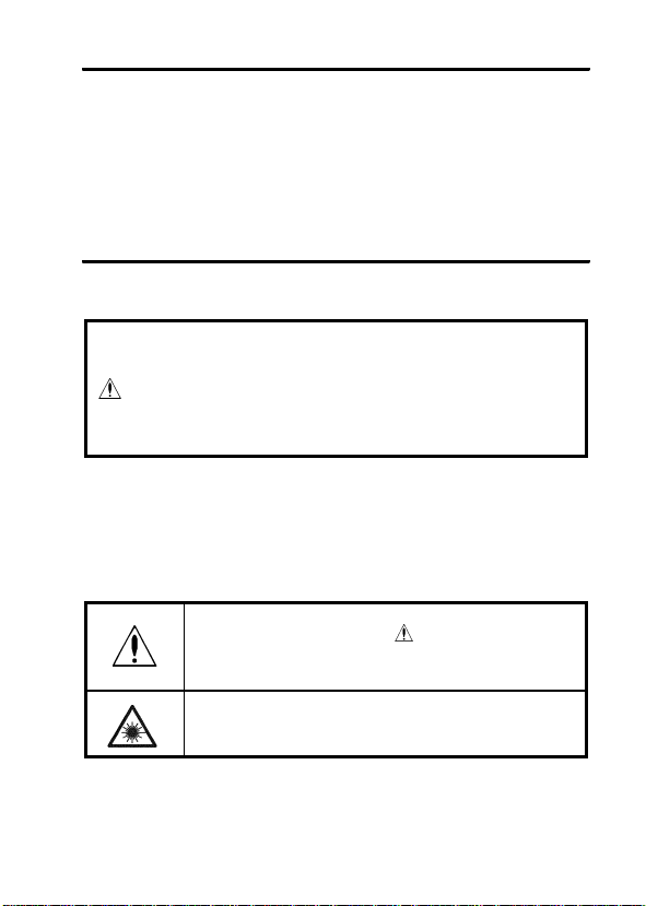
○安全記号
書を熟読し、十分に内容を理解してから操作して
ください。万一事故があっても、弊社製品が原因で
ある場合以外は責任を負いかねます。
使用者は、取扱説明書内の マークのあるところ
は、必ず読み注意する必要があることを示します。
1
レーザに対する警告を示します。
―――――――――――――――――――――――
Page 7
2
――――――――――――――――――――――――――
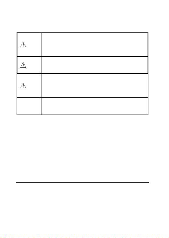
取扱説明書の注意事項には、重要度に応じて以下の表記がさ
れています。
操作や取り扱いを誤ると、使用者が死亡または重
傷につながる危険性が極めて高いことを意味しま
危険
す。
操作や取り扱いを誤ると、使用者が死亡または重
警告
傷につながる可能性があることを意味します。
操作や取り扱いを誤ると、使用者が傷害を負う場
合、または機器を損傷する可能性があることを意
注意
味します。
注記
○確度について
・
○使用前の確認
・使用前には、保存や輸送による故障がないか、点検と動作確
製品性能および操作上でのアドバイス的なことを
意味します。
(読み値、表示値、指示値)
rdg.
現在測定中の値、測定器が現在指示している値を表します。
認をしてから使用してください。故障を確認した場合は、お
買上店(代理店)か最寄りの営業所にご連絡ください。
点検
本器がお手元に届きましたら、輸送中において異常または破
損がないか点検してからご使用ください。特に付属品および
液晶表示部や操作キー、レンズに注意してください。
万一、破損あるいは仕様どおり動作しない場合は、お買上店
(代理店)か最寄りの営業所にご連絡ください。
―――――――――――――――――――――――
Page 8
――――――――――――――――――――――――――
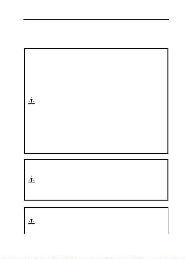
ご使用にあたっての注意
本器を安全にご使用いただくために、また機能を十二分に
ご活用いただくために、下記の注意事項をお守りください。
・ここに規定した以外の手順による操作は、危険
なレーザ放射の被爆をもたらします。
・3415-01(2 ビームレーザマーカタイプ)は、光源
として可視光半導体レーザを使用しており、JIS
規格(JIS C6802)のクラス 2 に相当します
(波長 670 nm、最大出力 1mW)。
危険
警告
このレーザ光は目に障害を与える危険がありま
すので、レーザ光が直接目に入らないように注
意してください。
・光学機器で、直接レーザ光を見ないでください。
・鏡面状の物体を測定する場合には、その反射光
が目に入らないように注意してください。
・レーザ光が爆発性のガスに触れないようにして
ください
・本器をぬらしたり、ぬれた手で測定しないでく
ださい。感電事故の原因になります。
・本器の保護機能が破損している場合は、使用で
きないように廃棄するか、知らないで動作させ
ることのないように、表示しておいてください。
3
・強力な電磁波を発生するもの、または帯電して
注意
いるものの近くで使用しないでください。誤動
作の原因となります。
―――――――――――――――――――――――
Page 9
4
――――――――――――――――――――――――――
・本器の使用環境および設置場所は使用温湿度範
囲 0〜40℃(3415-01)、0〜50℃(3416-01,3418)、
35〜80% rh 以下の屋内です。
・直射日光や高温、多湿、結露するような環境下で
の、保存や使用はしないでください。変形、絶縁
劣化を起こし、仕様を満足しなくなります。
・本器は防じん・防水構造となっていません。
ホコリの多い環境や水のかかる環境下で使用し
ないでください。故障の原因になります。
・腐食性ガスや爆発性ガスが発生する場所では使
注意
注記
・使用前には、保存や輸送による故障がないか、点検と動作確
認をしてから使用してください。
・電池消耗時は
んので、ただちに交換してください。
用しないでください。本器の破損もしくは、爆発
事故を誘発する可能性があります。
・本器の損傷を防ぐため、運搬および取り扱いの
際は振動、衝撃を避けてください。特に、落下な
どによる衝撃に注意してください。
・レンズを太陽光などの強い光に向けないでくだ
さい。センサを破壊する恐れがあります。
・測定対象物にレンズを接触させ汚したり、キズ
を付けたり、また異物を入れたりしないでくだ
さい。誤差の原因となります。
マークが点滅します。確度保証はできませ
―――――――――――――――――――――――
Page 10

――――――――――――――――――――――――――
第1章 概要
1.1 製品概要
1.測定原理
すべての物体は、温度に応じた赤外線エネルギーを放射して
います。そのエネルギー量を測定することで、その物体の温
度を測定することができます。
2.赤外線とは
赤外線とは、光(電磁波)の一種であり、空気中の透過力が大き
く物質に吸収されやすい性質を持っています。
赤外線検知方式放射温度計では、空気の温度や測定距離に関
係なく正確な測定ができます。
3.放射温度計の構成
物体から放射された赤外線を、赤外線透過レンズや8μmカ
ットオンフィルタ等の光学系で、赤外線センサへ集光します。
赤外線センサからの出力信号は、基準温度センサの出力信号
とともに、電気回路に入力されます。
電気回路で、基準温度の補正や、放射率の補正などをほどこ
して温度に換算し、表示します。
5
―――――――――――――――――――――――
第1章 概要
Page 11
6
――――――――――――――――――――――――――
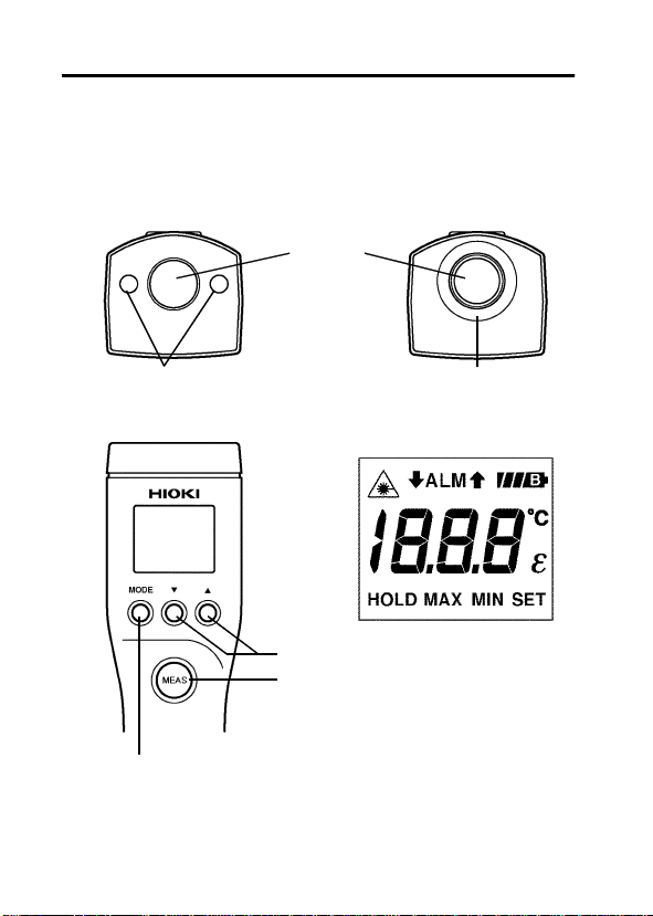
1.2 各部の名称と機能 3415-01 2 ビームレーザ
マーカタイプ
3418 スタンダードタイプ
②レーザマーカ
照射口(3415-01)
④MODE キー
3416-01 LED スポット
マーカタイプ
①レンズ
③LED マーカ
照射口
⑦LCD ディスプレイ
⑤数値入力キー
⑥MEAS キー
―――――――――――――――――――――――
第1章 概要
Page 12

――――――――――――――――――――――――――
①レンズ
測定対象物の赤外線をここより受光します。
②レーザマーカ照射口(3415-01)
ここからレーザマーカが照射されます。
③LED マーカ照射ロ(3416-01)
ここから
④MODE キー
押すごとに、ε→
り換わります。
・
HOLD
・
ε
・
ALM↑
・
↓ALM
・
MAX
・
MIN
⑤数値入力キー
・▼キー :数値が減少します。
・▲キー :数値が増加します。
数値キーを押し続けると、数字は早く変化します。
⑥MEAS キー
押すと電源が入り、測定を開始します。離すと測定を終了し
ます。
⑦LCD ディスプレイ
・
・
・
℃
マーカが照射されます。
LED
ALM↑→↓ALM→MAX→MIN→HOLD
:測定終了後は
ドします。
:物体固有の放射率を▼▲キーで設定します。
:上限アラーム温度を▼▲キーで設定します。
:下限アラーム温度を▼▲キーで設定します。
:測定中の最高温度を表示します。
:測定中の最低温度を表示します。
:レーザマーカの発光/非発光の設定を表示して
います。発光設定の測定中はこの表示が点滅し
ます
(3415-01)
:電池残量を表示しています。電池が確度保証電
圧以下になったら
:摂氏温度を表示するとき点灯します。
が点灯し、測定値をホール
HOLD
。
マークのみが点滅します。
と切
7
―――――――――――――――――――――――
第1章 概要
Page 13

8
――――――――――――――――――――――――――
・
HOLD
・
ε
・
ALM↑
・
↓ALM
・
MAX
・
MIN
・
SET
:最後に測定した値をホールドしている時に点灯
します。
:放射率設定時に点灯します。
:上限アラーム温度設定時に点灯します。
:下限アラーム温度設定時に点灯します。
:測定中の最高温度を表示するときに点灯します。
:測定中の最低温度を表示するときに点灯します。
:数値を設定できるときに点減します
(ε、ALM↑、ALM↓
設定時)。
―――――――――――――――――――――――
第1章 概要
Page 14

――――――――――――――――――――――――――
第2章 測定方法
2.1 電源オン
電源オフのとき
ディスプレイには、前回、電源が切れる直前の画面が表
LCD
示されます。
キーを押すと電源が入ります。
MEAS
9
電源オフの状態から
注記
測定を開始します。
―――――――――――――――――――――――
キーを1秒以上押し続けると
MEAS
第2章 測定方法
Page 15
10
――――――――――――――――――――――――――
2.2 温度測定
1. MODE
アスファルト
コンクリート
セメント
砂
土
水
氷
雪
ガラス
セラミック
大理石
石膏
しっくい
れんが(赤色
注記
―――――――――――――――――――――――
第2章 測定方法
キーを押してεマークを点灯させます。
以下の表を参考に、▼▲キーを用いて測定対象物の放射率を
設定します。
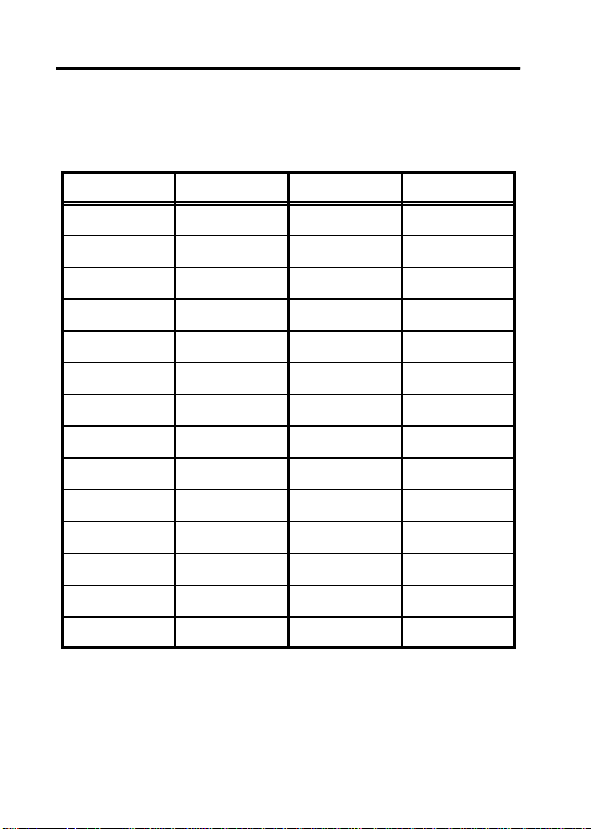
品名 放射率 品名 放射率
布(黒色
0.90〜0.98
0.94
0.96
0.90
0.92〜0.96
0.92〜0.96
0.96〜0.98
0.83
0.90〜0.95
0.90〜0.94
0.94 Cr
0.80〜0.90 Cu
0.89〜0.91 Fe
0.93〜0.96
)
放射率(ε)は測定対象物の表面の状態や色により多少異
なります。温度を正確に測定したい場合や、放射率のわ
からないものの温度を測定したいときは、別売りの黒体
テープ、黒体スプレーを使用してください。
放射率(ε)は黒体テープ、黒体スプレーに示されている
値に設定してください。
)
人の皮膚
なめし皮
木炭(粉
)
塗装ラッカー
〃(艶消し
ゴム(黒
プラスチック
材木
紙
繊維
)
)
酸化物
酸化物
酸化物
0.98
0.98
0.75〜0.80
0.96
0.80〜0.95
0.97
0.94
0.85〜0.95
0.90
0.70〜0.94
0.81
0.78
0.78〜0.82
0.90
Page 16
――――――――――――――――――――――――――
レンズを測定対象物に向けます。
2.
3. MEAS
キーを押します。
キーを押している間測定を行います。
MEAS
11
3415-01で
危険
4.
しています。レーザマーカが目(目に障害)に入ら
ないように注意してください。
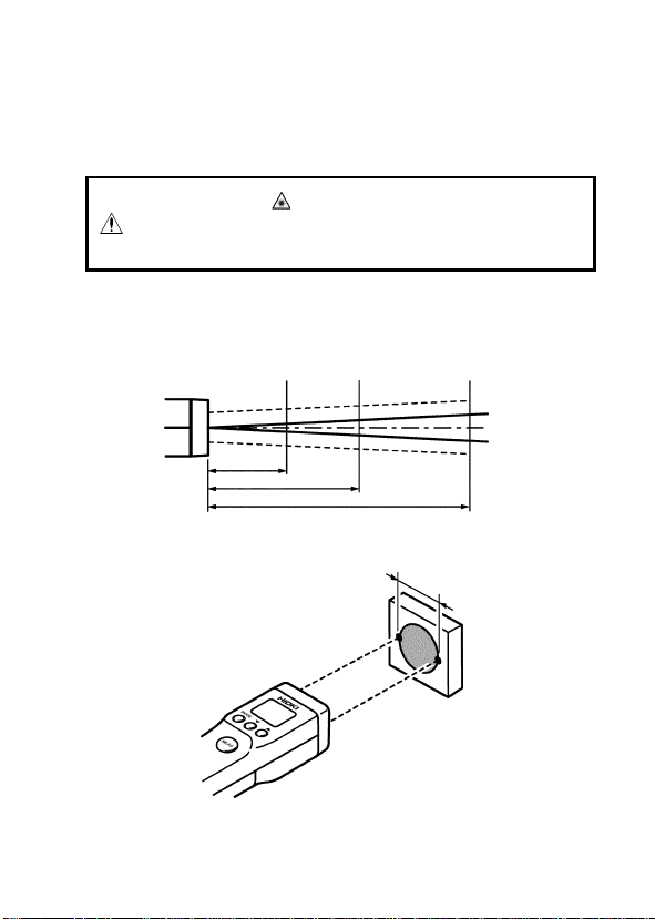
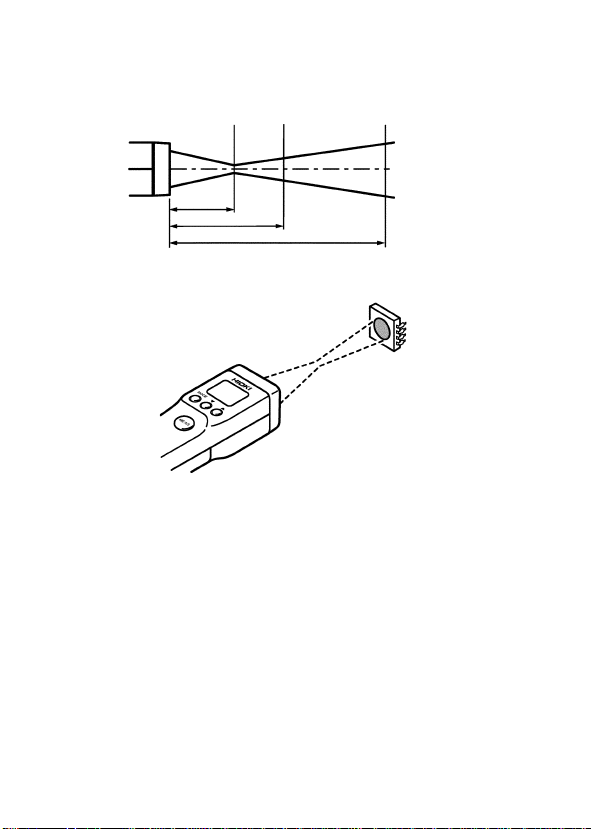
図を参照して測定対象物に照準をあわせます。
3415-01/3418
φ14
()内寸法は、照準を示します。
マーク点滅中は、レーザマーカを発光
φ40
500
(60)
1000
φ72
(95)
2000
レーザマーカは測定視野径
の両サイドに照射されます
(3415-01)。
φ140
(163)
(mm)
対象物
測定視野径
―――――――――――――――――――――――
第2章 測定方法
Page 17
12
――――――――――――――――――――――――――
3416-01
測定視野と照準はほぼ一致していますが、測定視野は光
注記
学応答
よりも十分大きいことが必要です
表示部を読みます。
5.
注記
・
・測定値が測定温度範囲
キーを離すと測定が終了し、マーカが
MEAS
定値がホールドされます。15秒後に電源が切れます。
します。
φ2.5
φ10.1 φ32.4
30
マーカは 30 mm でピントが合います。
90%
50
の測定径です。測定対象物の大きさは測定径
(-50〜500℃)
100
(mm)
対象物
◎マーカが明瞭になると
ころが最小スポット径(φ2.5)
です。
倍以上)。
(1.5〜2
OFF
から外れると表示が点滅
になり、測
―――――――――――――――――――――――
第2章 測定方法
Page 18

――――――――――――――――――――――――――
13
2.3 連続測定
電源オフ状態で、
1.
キーを押しながら
MODE
MEAS
キーを押す
と、連続測定モードになります。
2. MEAS
キーを押すごとに、測定、
が切り換ります。
HOLD
注記
・連続測定モードでは、オートパワーオフ機能が働きませんの
で、必ず
状態にして測定を終了してください。15秒後
HOLD
に電源が切れます。
・連続測定モードを設定したとき、レーザマーカ
び
で
マーカ
LED
MEAS
(3416-01)
キーを押している間だけ点灯します。)
は点灯しません。(マーカは測定中
(3415-01)
およ
2.4 放射率(ε)の設定方法
測定対象物に黒体テープを貼るか、黒体スプレーを吹き付け
1.
ます。
放射率設定画面にし、放射率(ε)を黒体テープ(黒体スプレー
2.
に示されている値に設定します。
3. MEAS
4.
キーを押し、黒体テープ(黒体スプレー)のついている
部分の温度
を測定します。
(T
)
real
黒体テープ(黒体スプレー)のついていない部分の温度
(T)
測定します。
放射率(ε)を変更します。
5.
6. T=T
となったときの放射率(ε)の値が、測定対象物の固有
real
放射率となります。
)
を
2.5 上下限アラーム温度設定
1. MODE
2.
キーを押して
ALM↑(↓ALM)
▼▲キーを押して上限(下限)アラーム温度を設定します。
―――――――――――――――――――――――
マークを点灯させます。
第2章 測定方法
Page 19

14
――――――――――――――――――――――――――
2.6 最高温度、最低温度表示
1. MODE
2.
2.7 レーザマーカの発光設定(3415-01)
2.8 電源オフ
注記
キーを押して
表示部には、測定中の最高(最低)温度が表示されます。
測定中または表示部が
▲キーを押すと、レーザマーカの発光、非発光が切り換わり
ます。
レーザマーカ発光設定時は表示部にマークが点灯します。
本器にはオートパワーオフ機能があり、15秒間操作を行わな
ければ電源が切れます。
測定した値をもう一度確認したいときは、一度だけ
ーを押してください。
測定中、オートパワーオフ機能は働きません。
MAX(MIN)
HOLD、MAX、MIN
マークを点灯させます。
となっているとき
MEAS
キ
―――――――――――――――――――――――
第2章 測定方法
Page 20
――――――――――――――――――――――――――
2.9 電池交換
電池交換時には、まちがって MEAS キーを押さな
危険
警告
いでください。レーザマーカが目に入ることがあ
りますので危険です。また交換後は必ずふたをし
てから使用してください。
・新旧および異種の混合はしないでください。ま
た極性+−に注意し、逆挿入しないでください。
性能劣化や液漏れの原因になります。
・使用済の電池をショート、分解または火中への
投入はしないでください。破裂する恐れがあり
危険です。
・使用済の電池は地域で定められた規則に従って
処分してください。
15
―――――――――――――――――――――――
第2章 測定方法
Page 21
16
――――――――――――――――――――――――――
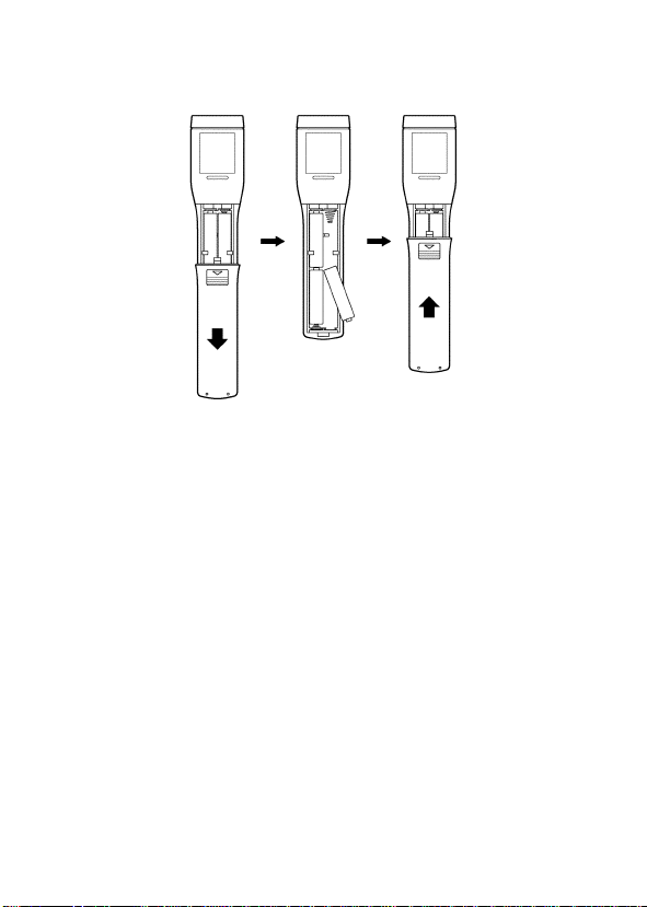
・図を参考に以下の手順で交換してください。
下ケース
単 4
裏ぶた
下ケース(本体底面)を上にし、裏ぶたを外します。
1.
極性に注意して電池を交換します。
2.
裏ぶたをはめます。
3.
―――――――――――――――――――――――
第2章 測定方法
裏ぶた
Page 22

――――――――――――――――――――――――――
17
第3章 仕様
3.1 一般仕様(3415-01)
形式
測定温度範囲
表示分解能:1
確度保証温湿度範囲:23℃±5℃、80%rh
確度保証期間
測定精度
201〜500℃ :±1% rdg .
0
再現性:±1℃(0〜500℃)
測定視野
検出素子/光学レンズ
測定波長:8〜16μm
サンプリングレート
応答時間
照準
放射率補正
上下限アラーム機能
オートパワーオフ:15秒(
〜
−50〜−1℃ :±
:
3415-01
(2
:−50℃〜
:1年間
200℃ :±2
ε
周囲湿度
±2℃
:φ72/
:サーモパイル/シリコン
:2回/秒
:
1.5秒(95%
:2ビームレーザマーカ(クラス2)
:
0.10〜1.00、0.01
:設定範囲
―――――――――――――――――――――――
放射温度ハイテスタ
ビームレーザマーカタイプ
℃
500
℃
以下
℃
10%rdg.+2
=1.00
℃
、ケース温度23±5℃、
55%rh
(-50〜-1℃)
1000 mm
応答)
ステップ
-55〜505
連続測定モード設定時は除く
℃
)
)
第3章 仕様
Page 23

18
――――――――――――――――――――――――――
その他の機能
電源
最大定格電力:342 mVA(MAX)
Batt- Lo 点滅電圧
使用周囲温度:0〜40
使用周囲湿度
保存温度
使用場所
外形寸法
質量
適合規格
付属品
:瞬時・ホールド・
え
:単4形乾電池
連続約40時間:レーザマーカ非点灯
(
:
4.4±0.2 V
℃
:35〜
85% rh
:−20〜55℃(結露なきこと)
:高度
2000 m
:約
40W×170H×36D m m
:約
:
:取扱説明書,携帯用ケース
電池含む
140g(
EMC EN61326
電池(単4形乾電池
MAX・MIN
(R03)×4DC1.5V×4
(結露なきこと)
まで、屋内
)
,
(R03)×4
切り換
)
)
―――――――――――――――――――――――
第3章 仕様
Page 24

――――――――――――――――――――――――――
19
3.2 一般仕様(3416-01)
形式
:
3416-01
(LED
測定温度範囲
:−50℃〜
表示分解能:1
放射温度ハイテスタ
スポットマーカタイプ
℃
500
℃
確度保証温湿度範囲:23℃±5℃、80%rh
確度保証期間
:1年間
測定精度
201〜500℃ :±1% rdg .
0
〜
200℃ :±2
−50〜−1℃ :±
℃
10%rdg.+2
ε
=1.00
周囲湿度
℃
、ケース温度23±5℃、
55%rh
再現性:±1℃(0〜500℃)
±2℃
(-50〜-1℃)
:φ
測定視野
検出素子/光学レンズ
2.5/30 mm
:サーモパイル/シリコン
測定波長:8〜16μm
サンプリングレート
応答時間:1.5秒(95%
照準
放射率補正
上下限アラーム機能
オートパワーオフ:15秒(
その他の機能
:2回/秒
応答)
:赤色
:
0.10〜1.00、0.01
:設定範囲
スポットマーカ
LED
-55〜505
連続測定モード設定時は除く
:瞬時・ホールド・
ステップ
MAX・MIN
え、
電源
最大定格電力
:単4形乾電池
(連続約40時間:
:
180 mVA(MAX)
(R03)×4DC1.5V×4
LED
Batt- Lo 点滅電圧:4.4±0.2 V
)
以下
℃
)
切り換
マーカ非点灯)
―――――――――――――――――――――――
第3章 仕様
Page 25

20
――――――――――――――――――――――――――
使用周囲温度:0〜50
使用周囲湿度:35〜85% rh
保存温度
使用場所
外形寸法:約40W×170H×36D m m
質量
適合規格:EMC EN61326
付属品
℃
(結露なきこと)
:−20〜55℃(結露なきこと)
:高度
:約
140g(
:取扱説明書,携帯用ケース
電池(単4形乾電池
2000 m
電池含む
まで、屋内
)
,
(R03)×4
)
―――――――――――――――――――――――
第3章 仕様
Page 26

――――――――――――――――――――――――――
21
3.3 一般仕様(3418)
:
形式
測定温度範囲
表示分解能:1
確度保証温湿度範囲:23℃±5℃、80%rh
確度保証期間
放射温度ハイテスタ
3418
スタンダードタイプ
(
:−50℃〜
500
℃
:1年間
)
℃
以下
測定精度
201〜500℃ :±1% rdg .
0
〜
200℃ :±2
−50〜−1℃ :±
℃
10%rdg.+2
ε
=1.00
周囲湿度
℃
、ケース温度23±5℃、
55%rh
再現性:±1℃(0〜500℃)
±2℃
(-50〜-1℃)
測定視野
検出素子/光学レンズ
:φ72/
:サーモパイル/シリコン
1000 mm
測定波長:8〜16μm
サンプリングレート
応答時間:1.5秒(95%
照準
放射率補正
上下限アラーム機能
オートパワーオフ:15秒(
その他の機能
:2回/秒
応答)
:なし
:
0.10〜1.00、0.01
:設定範囲
-55〜505
連続測定モード設定時は除く
:瞬時・ホールド・
ステップ
℃
MAX・MIN
)
切り換
え、
電源
:単4形乾電池
(R03)×4DC1.5V×4
(連続約40時間)
:
最大定格電力
72 mVA(MAX)
Batt- Lo 点滅電圧:4.4±0.2 V
―――――――――――――――――――――――
第3章 仕様
Page 27

22
――――――――――――――――――――――――――
使用周囲温度:0〜50
使用周囲湿度:35〜85% rh
保存温度
使用場所
外形寸法:約40W×170H×36D m m
質量
適合規格:EMC EN61326
付属品
℃
(結露なきこと)
:−20〜55℃(結露なきこと)
:高度
:約
140g (
:取扱説明書,携帯用ケース
電池(単4形乾電池
2000 m
電池含む
まで、屋内
)
,
(R03)×4
)
―――――――――――――――――――――――
第3章 仕様
Page 28

――――――――――――――――――――――――――
23
第4章 保守・サービス
本器の保護機能が破損している場合は、使用でき
警告
ないように廃棄するか、知らないで動作させるこ
とのないように、表示しておいてください。
―――――――――――――――――――――――
第4章 保守・サービス
Page 29

24
――――――――――――――――――――――――――
・本器の汚れをとるときは、柔らかい布に水か中
性洗剤を少量含ませて、軽くふいてください。ベ
ンジン、アルコール、アセトン、エーテル、ケト
ン、シンナー、ガソリン系を含む洗剤は絶対に使
用しないでください。変形、変色することがあり
ます。
・電池の液漏れによる腐食を防ぐため、長い間使
用しないときは、電池を抜いて保管してくださ
い。
・故障と思われるときは、電池の消耗、プローブ部
の接続を確認してから、お買上店(代理店)か最
注意
寄りの営業所にご連絡ください。
・修理に出される場合は、輸送中に破損しないよ
うに電池をすべて取り外してから、梱包してく
ださい。箱の中で本器が動かないように、クッシ
ョン材などで固定してください。また、故障内容
も書き添えてください。
輸送中の破損については保証しかねます。
・レンズが汚れているときは、カメラのレンズを
掃除するブロアなどを使ってレンズのホコリを
取り除いてください。
・汚れがひどい時は、綿棒にアルコールを少量含
ませて拭き取ってください。
―――――――――――――――――――――――
第4章 保守・サービス
Page 30

――――――――――――――――――――――――――
4.1 故障かなと思ったら
症 状 原 因 対 策
表示がでない電池切れまたは入れ間違い電池を交換または正し
く入れ直してください
測定値がお
かしい
が表示
Err
される
○サービス
対策後も上記の症状が直らない場合は、故障している可能性
があります。お買上店(代理店)か最寄りの営業所にご連絡
ください。
○校正
本器の確度維持あるいは確認には、定期的な校正が必要です。
修理・校正業務のご用命は、「日置エンジニアリングサービス
(株)」までお願いいたします。(
0268-28-0824
レンズが汚れている レンズを清掃してくだ
さい
近くに高温物体などの
熱源がある
放射率の値が適切でない放射率を適切な値にし
故障です お求めの販売店へご連
)
しゃへい板等で熱源を
遮断してください
てください
絡ください
TEL 0268-28-0823、FAX
25
―――――――――――――――――――――――
第4章 保守・サービス
Page 31

26
――――――――――――――――――――――――――
4.2 測定のアドバイス
Q:ガラス越しに温度を測定したい
A:一般のガラスは、本器で測定している波長(8〜16μm)
の赤外線を吸収してしまいます。したがって、本器では
ガラスの向こうにある物体の温度を計ることはできず、
ガラス自体の温度を測定していることになります。
Q:光があたっている物体の温度を測定したい
A:蛍光灯は赤外線をほとんど照射しませんので、通常の測
定にはほとんど影響ありません。
しかし、太陽光や白熱電球は本器で測定している波長の
赤外線を照射していますので、測定誤差が大きくなる可
能性があります。
Q:気体や炎の温度を測定したい
A:気体や炎は赤外線を透過しますので、気体や炎そのもの
の温度は測定できません。
Q:雨や霧を通して測定したい
A:雨や霧は赤外線を反射、吸収してしまいますので、正確
な測定はできません。
Q:測定する距離によって測定値は変わらないか
A:本器で測定している波長(8〜16μm)の赤外線は、空気
にはほとんど吸収されません。したがって、測定距離に
関係なく正確な測定ができます。
―――――――――――――――――――――――
第4章 保守・サービス
Page 32

保 証 書
形名
3415-01
3416-01
3418
本製品は、弊社の厳密なる検査を経て合格した製品をお届けした物です。
万一ご使用中に故障が発生した場合は、お買い求め先にご連絡ください。
本書の記載内容で無償修理をさせていただきます。また、製品の使用による損失について
は、購入金額までの支払いとさせていただきます。なお、保証期間は購入日より3年間で
す。購入日が不明の場合は、製品の製造月から3年を目安とします。ご連絡の際は、本書
を提示してください。また、確度については、明示された確度保証期間によります。
お客様 ご住所: 〒
*お客様へのお願い
・保証書の再発行はいたしませんので、大切に保管してください。
・「形名、製造番号、購入日」およびお客様「ご住所、ご芳名」は恐れ入りますが、お
客様にて記入していただきますようお願いいたします。
1.取扱説明書・本体注意ラベル(刻印を含む)などの注意事項にしたがった正常な使用
状態で保証期間内に故障した場合には、無償修理いたします。また、製造後一定期間
を経過したものおよび部品の生産中止、不測の事態の発生などにより修理不可能と
なった場合は、修理、校正などを辞退する場合がございます
2.保証期間内でも、次の場合には保証の対象外とさせていただきます。
−1.製品を使用した結果生じる被測定物の、二次的、三次的な損傷、被害
−2.製品の測定結果がもたらす二次的、三次的な損傷、被害
−3.取扱説明書に基づかない不適当な取り扱い、または使用による故障
−4.弊社以外による不当な修理や改造による故障および損傷
−5.取扱説明書に明示されたものを含む、部品の消耗
−6.お買い上げ後の輸送、落下などによる故障および損傷
−7.外観上の変化(筐体のキズなど)
−8.火災、風水害、地震、落雷、電源異常(電圧、周波数など)、戦争・暴動行為、
−9.保証書の提出が無い場合
−10.その他弊社の責任とみなされない故障
−11.特殊な用途(宇宙用機器、航空用機器、原子力用機器、生命に関わる医療用
3.本保証書は日本国内のみ有効です。(
サービス記録
年月日 サービス内容
製造番号 保証期間
購入日 年 月より3年間
ご芳名:
放射能汚染およびその他天災地変などの不可抗力による故障および損傷
機器及び車輌制御機器など)に組み込んで使用する場合で、前もってその旨
を連絡いただかない場合
This warranty is valid only in Japan.)
386-1192
〒
TEL 0268-28-0555
FAX 0268-28-0559
長野県上田市小泉81
06-03
Page 33

外国主要販売ネットワーク
外国代理店については
ご覧いただくか、最寄りの営業所または本社
販売企画課までお問い合わせください。
URL http: //www.hioki.com/
HIOKI USA CORPORATION
6 Corporate Drive, Cranbury, NJ 08512 USA
TEL +1-609-409-9109
FAX +1-609-409-9108
E-MAIL hioki@hiokiusa.com
HIOKI
ホームページを
Page 34

HIOKI 3415-01,3416-01,3418 放射温度ハイテスタ
取扱説明書
発行年月
編集 ・ 発行 日置電機株式会社
問合せ先 日置電機株式会社
TEL: 0268-28-0560
FAX: 0268-28-0579
E-mail: info@hioki.co.jp
URL http: //www.hioki.co.jp/
2008年9
開発支援課
販売企画課
〒
月 改訂6版
0120-72-0560
386-1192
長野県上田市小泉
81
Pri nt e d in J a pa n 3418A980-06
・本書の内容に関しては万全を期していますが、ご不明な
点や誤りなどお気づきのことがありましたら、本社 販売
企画課または最寄りの営業所までご連絡ください。
・本書は改善のため予告なしに記載事項を変更すること
があります。
・本書を無断で転載、複製することは禁止されています。
Page 35

Page 36

3415-01
3416-01
3418
TEMPERATURE
HiTESTER
INSTRUCTION MANUAL
Page 37

Page 38

Introduction
Safety Notes
Inspection
Notes on Use
Contents
i
ii
iv
v
Chapter 1 Summary
1.1 Product Summary 1
1.2 Names and Functions of Parts
Chapter 2 Making Measurements 7
2.1 Turning the Power On 7
2.2 Measuring Temperature
2.3 Continuous Measurement
2.4 How to Specify the Thermal
Emissivity(ε)
2.5 Setting the Upper and Lower Alarm
Temperatures
2.6 Displaying the Maximum and Minimum
Temperatures
2.7 Switching On the Laser Marker Beem
(3415-01)
2.8 Turning the Power Off
2.9 Changing the Batteries
12
12
13
13
14
14
15
Chapter 3 Specification 17
3.1 General Specification 3415-01 17
3.2 General Specification 3416-01
3.3 General Specification 3418
19
21
1
3
7
Page 39

Chapter 4 Maintenance and Service 23
4.1 Troubleshooting 25
4.2 Questions and Answers about
Measurement
26
Page 40

―――――――――――――――――――――――――――
Introduction
Tha n k you for purc hasi ng the Hioki "341501/3416-01/3418 Te mp e r a t u r e Hi T es t er . To
obtain maxi mum performance from the
product, please r ead this manu al first, an d
keep it h an dy for futur e reference.
i
――――――――――――――――――――――――
Introduction
Page 41

ii
―――――――――――――――――――――――――――
Safety Notes
WARNING
Mishandling this product during use could result
in injury or death, as well as damage to the
product. Be certain that you understand the
instructions and precautions in the manual before
use. We disclaim any responsibility for accidents
or injuries not resulting directly from product
defects.
This Instruction Manu al provides information
and warnings essential for operating this
equipment in a safe manne r and for
maintaining it in safe operating condition.
Before using this equipment, be sure to
carefully r ea d t he following safety notes.
Safety symbols
In the manual, this mark indicates
explanations which it is particularly
important that the user read before using
the product.
Indicates warnings relating to the laser.
――――――――――――――――――――――――
Safety Notes
Page 42

―――――――――――――――――――――――――――
iii
The following symbols ar e us ed in th i s
Instru ction Man u al to in dicate t he relative
importanc e of cautions an d war nin gs.
Indicates that incorrect operation
DANGER
presents extreme danger of accident
resulting in death or serious injury to
the user.
Indicates that incorrect operation
WARNING
presents significant danger of accident
resulting in death or serious injury to
the user.
Indicates that incorrect operation
CAUTION
presents possibility of injury to the user
or damage to the equipment.
Denotes items of advice related to
NOTE
performance of the equipment or to its
correct operation.
Accuracy
rdg. (displayed or indicated value)
This signifies t h e va lue actu all y being
measured, i.e., t he value t h at is currently
indicated or displayed by th e me asu ri ng
instrument.
――――――――――――――――――――――――
Safety Notes
Page 43

iv
―――――――――――――――――――――――――――
Check before use
Before usin g th e product, inspect it and check
the operation to ma ke s ure th at the product
was no t da ma ge d d ue to poor stor ag e or
tra ns po rt conditions. If da mag e is found,
contact your dealer or Hioki representative.
Inspection
Whe n you receive t h i s p rod uct, before use,
please check th at no abnormality or damage
has occurred during delivery. In particular,
be s ur e to check th e accessories, t h e liquid
cryst al displ ay, th e control keys, a n d th e lens.
In t he unlikely event of damage, or if t he
product does not function accord ing t o
specification, you should immediately contact
the dealer from whom you bought the
product, or th e ne ar es t Hioki service facility.
――――――――――――――――――――――――
Inspection
Page 44

―――――――――――――――――――――――――――
Notes on Use
In order to e nsure safe operation and to
obtain maxi mum performance from the
product, observe the cautions listed below.
DANGER
Operation of this product according to any
・
procedure not specified in this manual may
cause explosion due to dangerous laser
radiation.
The 3415-01 (2-beam laser marker type product)
・
uses as a light source a s emiconducting laser
which emits visible light, and which conforms to
JIS standard class 2 (JIS C6802). (Wavelength
670nm, maximum power output 1 mW)
Since there is considerable danger of this laser
light causing damage to the eyes, be very
careful not to direct this laser light into your
eyes or those of another person.
Do not look directly into the laser light from the
・
optical system.
When measuring the temperature of an object
・
which has a mirror finish, be careful not to allow
the laser light beam to be reflected off the
surface into your eyes or those of another
person.
Do not allow the laser light beam to impinge
・
upon any gas which can explode.
v
――――――――――――――――――――――――
Notes on Use
Page 45

vi
―――――――――――――――――――――――――――
WARNING
To avoid electric shock, do not allow the product
・
to get wet, and do not use it when your hands
are wet.
If the protective functions of the product are
・
damaged, either remove it from service or mark
it clearly so that others do not use it
inadvertently.
CAUTION
Do not use the product near a device that
・
generates a strong electromagnetic field or
electrostatic charge, as these may cause erroneous
measurements.
The product should always be operated indoors in a
・
range from 0
to 40 (3415-01), 0 to 50 (341601, 3418) and 35% to 80% RH or less.
Do not store or use the product where it could be
・
exposed to direct sunlight, high temperature or
humidity, or condensation. Under such conditions,
the product may be damaged and insulation may
deteriorate so that it no longer meets specifications.
――――――――――――――――――――――――
Notes on Use
Page 46

―――――――――――――――――――――――――――
CAUTION
This product is not designed to be entirely water- or
・
vii
dust-proof. To avoid damage, do not use it in a wet
or dusty environment.
Do not use the product where it may be exposed to
・
corrosive or combustible gases. The product may
be damaged or cause an explosion.
To avoid damage to the product, protect it from
・
vibration or shock during transport and handling,
and be especially careful to avoid dropping.
Do not point the lens at the sun or at any other
・
source of strong light. If you do, the s ensor may be
damaged.
Do not contact the lens against the object whose
・
temperature is to be measured, or get it dirty, allow
it to be scratched, or allow any foreign material to
adhere to it. Doing so may cause errors.
・ Before use, verify tha t no d a mag e ha s
NOTE
occurred due to careless stor age or t ran sp ort ,
and check th e appearance an d operation of
the product.
・ The "
" indicator flashes when the
remaining battery capacity is low. I n this
case, th e i nst rument 's reliability is not
guaranteed . Replace the b attery immediately.
――――――――――――――――――――――――
Notes on Use
Page 47

viii
―――――――――――――――――――――――――――
――――――――――――――――――――――――
Notes on Use
Page 48

―――――――――――――――――――――――――――
Chapter 1
Summary
1.1 Product Summary
1. Theory of M easure ment
Every object emits infrared energy in
accordance wit h its te mp e r at u r e. By
measuring the amount of this radiant energy,
it is possible to det er min e t h e t e mp er at ur e of
the emitting object.
2. About infra red
Infrared radiation is a form of light
(electromagnetic radiation), and has the
property tha t it passes easily throu gh air,
while it is easily absorbed by solid mat ter .
With a n emission th ermome ter which
operates by detecting i nfrared radiation,
accurate meas ureme nt is possible,
irrespective of the a ir temp er atu re or the
measurement distance.
1
3. Emission Ther mometer Structure
Infrared radiation which has been emitted
from t he object is focused upon an infrared
radiat io n sensor, via a n optical syste m which
includes a lens which is tr an s pa re n t to
――――――――――――――――――――――――
Chapter 1 Summary
Page 49

2
―――――――――――――――――――――――――――
infrared radiat ion, an 8 μmcutonfilter,etc..
The output signal from the infrared radiation
sensor is in p ut to a n electronic circuit along
with the output signal from a stand ard
temperature sensor.
The electronic circuit calculates the object
temperature while applying stan dard
tempe ratu re compensation, t her mal
emissivity compensation, etc., and displays
the result.
――――――――――――――――――――――――
Chapter 1 Summary
Page 50

―――――――――――――――――――――――――――
1.2 Names and Functions of Parts
3415-01 2-beam laser
marker type
3418 Standard type
3416-01 LED spot
marker type
(1) Lens
3
(2) Laser mark beam
emission openings(3415-01)
(5) Numeric input keys
(6) MEAS key
(4) MODE key
――――――――――――――――――――――――
(3) LED mark beam
emission opening
(7) LCD display
Chapter 1 Summary
Page 51

4
―――――――――――――――――――――――――――
(1) Lens
Infrared rays from the object whose
temperature is to be measured are received
here.
(2) Laser marker beam emission openings (3415-
01)
The laser ma rke r bea ms are emitted from
here.
(3) LED mark beam emission opening (3416-01)
The LED ma rk beam is emitted from here.
(4)
MODE
key
Pressing this key switches th e mode around
the cycleε→ALM
.
HOLD
→
ALM→MAX→MIN→
HOLD: After measurement is completed,
the HOLD indication appears, is
illuminated, an d the measured value is
held.
ε: The inherent thermal emissivityof the
object is set using the and keys.
: The upp er limit a la rm t emp erat ur e
ALM
is set using the
and keys.
ALM: The lower limit a la rm t emp era tur e
is set using the
and keys.
MAX: The maxi mum t emper atur e du ring
measurement is displayed.
MIN: The mini mum temper atur e during
measurement is displayed.
――――――――――――――――――――――――
Chapter 1 Summary
Page 52

―――――――――――――――――――――――――――
(5) Numeric input keys
key: The numerical value is reduced.
key: The nu merical value is increased.
If either of these numerical value keys is held
down, th e n umer ical value ch anges rapid ly in
the appropriate direction.
(6) MEAS key
When pressed, th e power is t urn ed on and
measurement starts. When released,
measurement is terminated.
(7) LCD display
:Indicates wheth er th e laser marke r b eam
is on or not. During measurement with the
laser mark er be am on, this indication
fla s h e s (3415-01).
:Shows the amount of battery
capacity r emaining. If t he batt ery voltage
drops below the minimum level to
guarantee accuracy, the
mark (only)
flashes.
:Turned on when th e display is showing
tempe ratu re in products of degrees Celsius.
HOLD: Appears when the last measured
tempe ratu re value is being held.
ε: Appears wh en th e th ermal emissivity is
being set.
: Appears when the upper limit
ALM
alarm temperature is being set.
ALM: Appears when th e lower limit
――――――――――――――――――――――――
Chapter 1 Summary
5
Page 53

6
―――――――――――――――――――――――――――
alarm temperature is being set.
MAX: Appears when the maximu m
temperature during measurement is being
displayed.
MIN: Appears when the minimum
temperature during measurement is being
displayed.
SET: Blinking when a numerical value can
be set.(during setting of ε, ALM
,and
ALM)
――――――――――――――――――――――――
Chapter 1 Summary
Page 54

―――――――――――――――――――――――――――
Chapter 2
Making Measurements
2.1 Turning the Power On
When th e power is off, pressing th e MEAS
key t u rn s on th e power.
The values an d sett ings on the LCD display
return to the state before the power was last
turned off.
7
・ If, fr om th e pow er off co nditio n, the
NOTE
key is held down for more t h an one second,
measurement starts.
MEAS
2.2 Measuring Temperature
1. P r e ss the
until the (ε) ma rk lights up.
Ref e r to t he followin g ta bl e and , us i ng t he
and keys, set the the rma l emissivity for
the object whose temperature is to be
measured.
MODE
――――――――――――――――――――――――
key, repeated ly if n ecessary,
Chapter 2 Making Measurements
Page 55

8
―――――――――――――――――――――――――――
Substance Thermal
emissivity
Asphalt 0.90 to 0.98 Cloth (black) 0.98
Concrete 0.94 Human skin 0.98
Cement 0.96 Leather 0.75 to 0.80
Sand 0.90 Charcoal
Earth 0.92 to 0.96 Lacquer 0.80 to 0.95
Water 0.92 to 0.96 Lacquer
Ice 0.96 to 0.98 Rubber
Snow 0.83 Plastic 0.85 to 0.95
Glass 0.90 to 0.95 Timber 0.90
Ceramic 0.90 to 0.94 Paper 0.70 to 0.94
Marble 0.94 Chromium
Plaster 0.80 to 0.90 Copper
Mortar 0.89 to 0.91 Iron oxides 0.78 to 0.82
Brick (red) 0.93 to 0.96 Textiles 0.90
Substance Thermal
emissivity
(powder)
(matt)
(black)
oxides
oxides
0.96
0.97
0.94
0.81
0.78
・ Variations in the surface condition and color
NOTE
of the object whose temperature is to be
measured may cause the th ermal emissivity ε
to be som ewhat different from th e va lues i n
the above table. If an accurate
――――――――――――――――――――――――
Chapter 2 Making Measurements
Page 56

―――――――――――――――――――――――――――
temperature measurement is desired for an
object whose therma l emissivity is not known,
black body ta p e or bl ack body sp r a y (sold
separately) should be used. In th is case the
setting for thermal emissivity (ε) should be
th e val u e i nd ic at ed on bla ck body ta p e o r
black body spr ay .
2. P oi nt th e len s a t th e object whose
temperature is to be measured.
3. P r e ss the MEAS key.
Measurement is performed as long as the
MEAS ke y is kep t pressed .
DANGER
With the 3415-01, whenever the indication is
flashing, the laser marker beam is being emitted.
Exercise extreme care not to allow the laser
marker beam to enter your eyes (because of this
laser light causing damage to the eyes) or those
of another person.
9
――――――――――――――――――――――――
Chapter 2 Making Measurements
Page 57

10
―――――――――――――――――――――――――――
4. Referring to the figure, aim the laser beam a t
the object whose temperature is to be
measured.
・ All dimension a re millimeters, and φ
represents a diameter.
3415-01/3418
φ14 φ40
(60)
φ72
(95)
φ140
(163)
500
The dimensions in parenthesis show the target.
――――――――――――――――――――――――
Chapter 2 Making Measurements
1000
2000
Target object
Measurement
field diameter
The laser marker beams
is aimed both sides of the
measurement field
diameter. (3415-01)
(mm)
Page 58

―――――――――――――――――――――――――――
3416-01
φ10.1 φ32.4
φ2.5
11
30
The marker beam is focused at a distance of 30 mm.
・ Although th e field of measuremen t and the
NOTE
sig h t i n g al m ost coincide, act u a l l y the field of
50
The place at which the "◎"
mark is clearest is where
the diameter of the spot is
smallest (2.5 mm).
100
measurement corresponds to the d iameter for
90% optical re spo ns e. The object whose
temperature is to be measured needs to be
larger t han t he measurement diameter by a n
adequate margin‐a t least 1.5 to 2 times
larger.
5. Read the display.
・ On releasin g
NOTE
key, measurement is
MEAS
terminated. Then, the marker is turned off
and the measurement dat a is held in display.
・ When the measurement value is out of the
measurement temperature range (-50 to 500
), the displa y wil l fla sh .
(mm)
Target object
――――――――――――――――――――――――
Chapter 2 Making Measurements
Page 59

12
―――――――――――――――――――――――――――
2.3 Continuous Measurement
1. With the power source off, th e product is pu t
into the continuous measu reme nt mode by
holding th e MODE key down and t he n
pressing the MEAS key.
2. An yti me
HOLD modes toggled.
・ An auto power off function does not operate
NOTE
in th e continuous meas ur emen t mode. Be
sure to retu rn to HOLD mode. The power goes
off a fte r 15 seconds.
・ During the continuous measu remen t mode,
the laser mark er (3415-01) or LED marke r
(3416-01) is n ot t u r n e d on. ( Ma rk e r is t u r n e d
on whenever MEAS key is p ressed.)
MEAS
key is pressed,
MEAS
and
2.4 How to Specify the Thermal Emissivity (ε)
1. St ick black body ta p e on t h e object whose
temperature is to be measured, or spray it
wit h black body spr ay .
2. Set t he the rma l emissivity value(ε)onthe
display screen to the value in dicated on b lack
body ta p e (black body spr ay).
3. P r e ss the
temperature (T
body ta p e (or black body spr ay) is app lie d.
key, so as to measure t he
MEAS
) of the part on which black
real
――――――――――――――――――――――――
Chapter 2 Making Measurements
Page 60

―――――――――――――――――――――――――――
4. Measure the temperature (T) of the parts to
which blac k body t a p e (or black body spra y) i s
not applied.
5. Change the th erma l emissivity (ε).
6. The val ue of t he th er mal emissivity (ε)at
which T comes out to be equal to T
correct valu e for t h e i n h er e n t th e r m a l
emissi vit y of th e body whose te mp e r a t u r e is
to be measu red.
real
13
is th e
2.5 Setting the Upper and Lower Alarm Temperatures
1. P r e ss the MODE key, repeate dly if necessary,
until the ALM
desired, appears.
2. P r e ss the
temp era tur e for the upper or lower limit
alarm.
mark or the
key or t he key to s et th e
ALM ma rk, as
2.6 Displaying the Maximum and Minimum Temperatures
1. P r e ss the
until the MAX mark or the MIN ma rk, as
desired, appears.
2. The maximum (or minimum) temperature
during measurement will be displayed on the
display.
MODE
――――――――――――――――――――――――
key, repeated ly if n ecessary,
Chapter 2 Making Measurements
Page 61

14
―――――――――――――――――――――――――――
2.7 Switching On the Laser Marker Beam (3415-01)
Switch the laser marker beam on and off by
pressing the
while the display shows
While the laser mar ker beam is on, t he m ar k
appears in the display.
key during measurement, or
HOLD,MAX
,or
MIN
.
2.8 Turning the Power Off
The product ha s a n auto power off function.
The power goes off a fte r 15 seconds if no
control act ion is pe rfor med.
If you need to check the measured
temp er at u re value agai n, just p ress th e
MEAS k e y on ce.
・ During measurement, the auto power off
NOTE
function does not operate.
――――――――――――――――――――――――
Chapter 2 Making Measurements
Page 62

―――――――――――――――――――――――――――
15
2.9 Changing the Batteries
DANGER
When changing the batteries, be careful not to
press the MEAS key by mistake.
It is ve ry dangerous to allow the laser beam to
shine into your e yes or those of another person.
Also, after changing the batteries, be sure to
close the cover before using the product.
WARNING
Do not mix old and new batteries, or different
・
types of batteries. Also, be careful to observe
battery polarity during installation. Otherwise,
poor performance or damage from battery
leakage could result.
To avoid the possibility of explosion, do not
・
short circuit, disassemble or incinerate
batteries.
Handle and dispose of batteries in accordance
・
with local regulations.
――――――――――――――――――――――――
Chapter 2 Making Measurements
Page 63

16
―――――――――――――――――――――――――――
Ref e r to the fi g u r e and follow the follo wing
procedure to change the batteries:
Lower case
R03 x 4
batteries
Rear lid
Rear lid
1. Lay the product down with the lower case
(the bo ttom surfa ce of t he product)
uppermost, an d remove the rea r lid.
2. Change the batteries, while being sure to pu t
the m in t he r ight way round.
3. Close t he rea r lid a ga i n.
――――――――――――――――――――――――
Chapter 2 Making Measurements
Page 64

―――――――――――――――――――――――――――
17
Chapter 3
Specification
3.1 General Specification 3415-01
Product type 3415-01 Tem p era t u r e Hi Tes te r
Measurement
temperature range
Display resolution 1
Temperature and
humidity for
guaranteed accuracy
Guaranteed accuracy
period
Accuracy of
measurement
Repeatability 1 (0 to 500 )
Diameter of field of
measurement
Detection element /
optical lens
Measurement
wavelength
Sampling rate 2 times/second
201 to 500
0 to 200
-50 to -1
(2-beamlasermarkertype)
-50 to 500 (-58 to 932 )
23 5 (73 9 ),
80% RH or le ss
1year
1% rdg .
2
10%rdg. 2
ε=1.0, t emperature of case 23
ambient humidity 55 %RH
2 (-50 to -1 )
72 mm (2.83") a t 1000 (39.37") m m
ther mop ile / silicon
8to16μm
5 ,
――――――――――――――――――――――――
Chapter 3 Specification
Page 65

18
―――――――――――――――――――――――――――
Response time 1.5 seconds (95% res ponse)
Sighting 2-beamlasermarker(class2)
Thermal emissivity
compensation
Upper and lower limit
alarm function
Auto power off 15 seconds (except when set to
Other functions Instant, hold, maximum, minimum
Power source Four R03/AAA dry batteries (1.5
Maximum rated power 342mVA (max.)
Batt-Lo light flashing
voltage
Ambient temperature
for use
Ambient humidity for
use
Storage temperature -20 t o 55 (-4 to 131 ); no
Location for use Indoor, altitude up to 2000 mm
Dimensions Approx. 40W x 1 70H x 36D mm
Mass Approx. 140 g (4.9 oz.)
Applicable standards EMC: EN61326
Accessories supplied instruction manua l
0.10 to 1.00 by ste ps of 0.01
setting ran ge -55 to 505 (-67 to
)
941
continuous measu rem ent mode)
VDC x 4) (Approx. 40 hou rs
continuous operation, with laser
mark er not illuminated)
4.4 0.2V
0to40 (32 to 104 )
35 to 85% RH; no condensat ion
condensation
(6562-ft.)
(1.57"W x 6.69"H x 1.42"D)
(excluding ba t teri es)
carrying case,
batteries (4 st anda rd dry cells,
R03/AAA x 4)
――――――――――――――――――――――――
Chapter 3 Specification
Page 66

―――――――――――――――――――――――――――
19
3.2 General Specification 3416-01
Product type 3416-01 Tem p era t u r e Hi Tes te r
Measurement
temperature range
Display resolution 1
Temperature and
humidity for
guaranteed accuracy
Guaranteed accuracy
period
Accuracy of
measurement
Repeatability 1 (0 to 500 )
Diameter of field of
measurement
Detection element /
optical lens
Measurement
wavelength
Sampling rate 2 times/second
Response time 1.5 seconds (95% res pons e)
Sighting red LED spot mark er
Thermal emissivity
compensation
Upper and lower limit
alarm function
201 to 500
0 to 200
-50 to -1
――――――――――――――――――――――――
(LED spot ma rk e r type)
-50 to 500 (-58 to 932 )
23 5 (73 9 ),
80% RH or le ss
1year
1% rdg .
2
10%rdg. 2
ε=1.0, t emperature of case 23
ambient humidity 55 %RH
2 (-50 to -1 )
2.5 mm (0.1") at 30 m m (1.18")
ther mop ile / silicon
8to16μm
0.10 to 1.00 by ste ps of 0.01
setting ran ge -55 to 505 (-67 to
)
941
Chapter 3 Specification
5 ,
Page 67

20
―――――――――――――――――――――――――――
Auto power off 15 seconds (except when set to
Other functions Instant, hold, maximum, minimum
Power source Four R03/AAA dry batteries
Maximum rated power 180 mVA (ma x.)
Batt-Lo light flashing
voltage
Ambient temperature
for use
Ambient humidity for
use
Storage temperature -20 t o 55 (-4 to 131 ); no
Location for use Indoor, altitude up to 2000 mm
Dimensions Approx. 40W x 1 70H x 36D mm
Mass Approx. 140 g (4.9 oz.)
Applicable standards EMC: EN61326
Accessories supplied instruction manua l
continuous measu rem ent mode)
(1.5 VDC x 4)
(Approx. 40 h ou r s conti nuous
operation, wit h LED ma rk er not
illuminated)
4.4 0.2V
0to50 (32 to 122 )
35 to 85% RH; no condensat ion
condensation
(6562-ft.)
(1.57"W x 6.69"H x 1.42"D)
(excluding ba t teri es)
carrying case,
batteries (4 st anda rd dry cells,
R03/AAA x 4)
――――――――――――――――――――――――
Chapter 3 Specification
Page 68

―――――――――――――――――――――――――――
21
3.3 General Specification 3418
Product type 3418 T em p er at u r e Hi Te ste r
Measurement
temperature range
Display resolution 1
Temperature and
humidity for
guaranteed accuracy
Guaranteed accuracy
period
Accuracy of
measurement
Repeatability 1 (0 to 500 )
Diameter of field of
measurement
Detection element /
optical lens
Measurement
wavelength
Sampling rate 2 times/second
Response time 1.5 seconds (95% res pons e)
Sighting None
Thermal emissivity
compensation
Upper and lower limit
alarm function
201 to 500
0 to 200
-50 to -1
――――――――――――――――――――――――
(standa rd type)
-50 to 500 (-58 to 932 )
23 5 (73 9 ),
80% RH or le ss
1year
1% rdg .
2
10%rdg. 2
ε=1.0, t emperature of case 23
ambient humidity 55 %RH
2 (-50 to -1 )
72 mm (2.83") a t 1000 mm (39.37")
ther mop ile / silicon
8to16μm
0.10 to 1.00 by ste ps of 0.01
setting ran ge -55 to 505 (-67 to
)
941
Chapter 3 Specification
5 ,
Page 69

22
―――――――――――――――――――――――――――
Auto power off 15 seconds (except when set to
Other functions Instant, hold, maximum, minimum
Power source Four R03/AAA dry batteries
Maximum rated power 72 mVA (max.)
Batt-Lo light flashing
voltage
Ambient temperature
for use
Ambient humidity for
use
Storage temperature -20 t o 55 (-4 to 131 ); no
Location for use Indoor, altitude up to 2000 mm
Dimensions Approx. 40W x 1 70H x 36D mm
Mass Approx. 140 g (4.9 oz.)
Applicable standards EMC:EN61326
Accessories supplied instruction manua l
continuous measu rem ent mode)
(1.5 VDC x 4)
(Approx. 40 h ou r s conti nuous
operation)
4.4 0.2V
0to50 (32 to 122 )
35 to 85% RH; no condensat ion
condensation
(6562-ft.)
(1.57"W x 6.69"H x 1.42"D)
(excluding ba t teri es)
carrying case,
batteries (4 st anda rd dry cells,
R03/AAA x 4)
――――――――――――――――――――――――
Chapter 3 Specification
Page 70

―――――――――――――――――――――――――――
23
Chapter 4
Maintenance and
Service
WARNING
If the protective functions of the product are
damaged, either remove it from service or mark it
clearly so that others do not use it inadvertently.
――――――――――――――――――――――――
Chapter 4 Maintenance and Service
Page 71

24
―――――――――――――――――――――――――――
CAUTION
To clean the product, wipe it gently with a soft cloth
・
moistened with water or mild detergent. Never use
solvents such as benzene, alcohol, acetone, ether,
ketones, thinners or gasoline, as they can deform
and discolor the case.
To avoid corrosion from battery leakage, remove
・
the batteries from the product if it is to be stored for
alongtime.
If the product seems to be malfunctioning, confirm
・
that the batteries are not discharged before
contacting your dealer or Hioki representative.
When sending the product for repair, remove the
・
batteries and pack carefully to prevent damage in
transit. Include cushioning material so the
instrument cannot move within the package. Be
sure to include details of the problem. Hioki cannot
be responsible for damage that occurs during
shipment.
If the lens is dirty, clean dust etc. off it using a
・
camera lens cleaning tissue, blower or similar
means.
If the lens is very dirty, clean it using a cotton bud
・
containing a small quantity of alcohol.
――――――――――――――――――――――――
Chapter 4 Maintenance and Service
Page 72

―――――――――――――――――――――――――――
25
4.1 Troubleshooting
Problem Cause Solution
No display Batteries exhausted,
Measured
temperature
value peculiar
The display
shows "Err"
poorly contacting, or
wrongly inserted.
Lens dirty Clean the lens.
A heat source such
as a high
temperature body is
present close by.
The thermal
emissivity value is
not appropriate.
The product is faulty. Contact a service
Service
If th e above sho wn solu tions fail to solve the
problem, it is possible th a t your product is
malfunctioning. Please contact your sales
agent or th e manufacturer to arrange for
repair.
Change the
batteries, or insert
them correctly.
Intercept radiation
from the heat source
by using an
insulation plate etc.
Set the thermal
emissivity to an
appropriate value.
facility.
――――――――――――――――――――――――
Chapter 4 Maintenance and Service
Page 73

26
―――――――――――――――――――――――――――
4.2 Questions and Answers about Measurement
Q: Why can't I measure the temperature on the
other side of a glass pane?
A: Normal glass absorbs infrared radiation of the
wavel eng th (8 to 16 μm) which t hi s device
uses for temperature measurement.
Therefore thi s device can not mea su re the
te m p e r a t u r e of a n object on th e ot he r side of
a glass sheet, but instead measures the
temperature of the glass sheet itself.
Q: Light is shining on an object. Why can't I
meas ur e it s t emp er at ur e accurately?
A: Since fluorescent light includes almost no
infrared radiation, it ha s almost no effect
upon normal tempe ratu re mea surem ent.
However sun light a nd incandescent lights
emit radiation which includes substantial
amounts of the infrared radiation used by this
device for temperature measurement, and
accordingly m a y p rod uce s igni ficant
mea s u r e m e n t d iscr epan cies.
――――――――――――――――――――――――
Chapter 4 Maintenance and Service
Page 74

―――――――――――――――――――――――――――
27
Q: Why can't I measure the temperature of a
gas, vapor, or flame?
A: Since gases, vapors, and flames are
transpar ent to infrared radiation, their
temperatures cannot be measured in this
way.
Q: Why can't I measure temperature through
rain or fog?
A: Since rain and fog reflect and absorb infrared
radiation, accurate measurement through
th e m is impossible.
Q: Doesn't the measurement distance affect the
resulting measured value for temperature?
A: Air hardly absorbs at all infrared radiation of
the wavelengths (8 to 16 μm) used by this
device for temperature measurement.
Therefore accurate t emperature measurement
is possible, irrespective of the measurement
distance.
――――――――――――――――――――――――
Chapter 4 Maintenance and Service
Page 75

Page 76

HIOKI 3415-01, 3416-01, 3418
TEMPERATURE HiTESTER
Instruction Manual
Publication date: September 2008 Revised edition 6
Edited and published by HIOKI E.E. CORPORATION
Technical Support Section
All inquiries to International Sales and Marketing
Department
81 Koizumi, Ue da, Nagano , 386-1192, J ap a n
TE L: +81-268-28-0562 / FAX: +81-268-28-0568
E-mail: os-com@hioki.c o.jp
URL:http://www.hioki.com/
Printed in Japan 3418A980-06
・
All reas onable care ha s been tak en in th e production of
this manual, but if you find any points which are
unclear or i n error, please contact your supplier or the
Sales and Marketing International Department at
HIOKI headquarters.
・
In the in terest s of product development, the contents of
this m anua l are subject to revision without prior
notice.
・
Unauthorized reproduction or copying of this manual is
prohibited.
Page 77

HEAD OFFICE
81 Koizumi, Ueda, Nagano 386-1192, Japan
TEL +81-268-28-0562 / FAX +81-268-28-0568
E-mail: os-com@hioki.co.jp/
URL http: //www.hioki.com/
HIOKI USA CORPORATION
6 Corporate Drive, Cranbury, NJ 08512, USA
TEL +1-609-409-9109 / FAX +1-609-409-9108
3418A980-06 08-09H
Printed on recycled paper
Page 78

Page 79

※お問い合わせは、最寄りの営業所または本社販売企画課まで。
3418A980-06 08-09H
この取扱説明書は再生紙を使用しています。
 Loading...