

Page 1

INSTRUCTION MANUAL
3403, 3404
TA CHO HiTESTER
Page 2

Page 3

Contents
Introduction 1
Inspection
Safety Notes
Notes on Use
1
2
6
Chapter 1 Overview
1.1 Product Overview 9
1.2 Names and Functions of Parts
10
Chapter 2 Measurement Method 13
2.1 Measurement Preparations 13
2.2 Normal Measurement
2.3 MAX Hold Measurement (3404 only)
2.4 MIN Hold Measurement (3404 only)
2.5 TOTAL Measurement (3404 only)
2.6 PERIOD Measurement (3404 only)
2.7 FAST/SLOW Mode Measurement
(3404 only)
2.8 Data Hold
2.9 Buzzer Off Set
15
16
17
18
20
22
23
24
Chapter 3 Precautions 25
Chapter 4 Analog Output (3404 only)
27
Chapter 5 Measurement with 9213
CONTACT ADAPTER 31
9
Page 4

Chapter 6 Specifications 33
Chapter 7 Maintenance and Service
7.1 Battery Replacement 39
7.2 Maintenance
7.3 Service
39
40
40
Page 5

____________________________________________
1
Introduction
Thank you for purchasing the HIOKI
"Model 3403,3404 TACHO HiTESTER".
To obtain maximum performance from
the instrument, please read this manual
first, and keep it handy for future
reference.
Inspection
When you receive the instrument,
inspect it carefully to ensure that no
damage occurred during shipping. If
damage is evident, or if it fails to operate
according to the specifications, contact
your dealer or Hioki representative.
____________________________________________
Page 6
2
____________________________________________
Safety Notes
DANGE R
This instrument is designed to comply
with IEC 61010 Safety Standards, and has
been thoroughly tested for safety prior to
shipment. However, mishandling during
use could result in injury or death, as
well as damage to the instrument. Be
certain that you understand the
instructions and precautions in the
manual before use. We disclaim any
responsibility for accidents or injuries not
resulting directly from instrument
defects.
This manual contains information and
warnings essential for safe operation of
the instrument and for maintaining it in
safe operating condition. Before using it,
be sure to carefully read the following
safety precautions.
Safety symbols
・The
・In the manual, the symbol indicates
symbol printed on the instrument
indicates that the user should refer to a
corresponding topic in the manual
(marked with the
using the relevant function.
particularly important information that
the user should read before using the
instrument.
symbol) before
____________________________________________
Page 7
____________________________________________
W
3
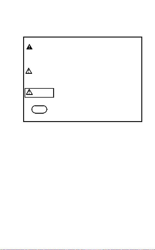
The following symbols in this manual
indicate the relative importance of
cautions and warnings.
DANGER
ARNING
CAUTION
NOTE
Indicates that incorrect operation
presents an extreme hazard that
could result in serious injury or death
to the user.
Indicates that incorrect operation
presents a significant hazard that
could result in serious injury or death
to the user.
Indicates that incorrect operation
presents a possibility of injury to the
user or damage to the instrument.
Advisory items related to
performance or correct operation of
the instrument.
Overvoltage Categories
This instrument complies with CAT I
safety requirements.
To ensure safe operation of
measurement instruments, IEC 60664
establishes safety standards for various
electrical environments, categorized as
CAT I to CAT IV, and called overvoltage
categories. These are defined as follows.
____________________________________________
Page 8

4
____________________________________________
CAT I: Secondary electrical circuits connected to
CAT II: Primary electrical circuits in equipment
CAT III: Primary electrical circuits of heavy
CAT IV: The circuit from the service drop to the
an AC electrical outlet through a
transformer or similar device.
connected to an AC electrical outlet by a
power cord (portable tools, household
appliances, etc.)
equipment (fixed installations) connected
directly to the distribution panel, and
feeders from the distribution panel to
outlets.
service entrance, and to the power meter
and primary overcurrent protection device
(distribution panel).
Higher-numbered categories correspond
to electrical environments with greater
momentary energy, so a measurement
device designed for CAT III environments
can endure greater momentary energy
than a device designed for CAT II. Using
a measurement instrument in an
environment designated with a highernumbered category than that for which
the instrument is rated could result in a
severe accident, and must be carefully
avoided.
____________________________________________
Page 9

____________________________________________
5
Accuracy
We define measurement tolerances in
terms of f.s. (full scale), rdg. (reading)
and dgt. (digit) values, with the following
meanings:
f.s. (maximum display value or scale length)
The maximum displayable value or scale
length. This is usually the name of the
currently selected range.
rdg. (reading or displayed value)
The value currently being measured and
indicated on the measuring instrument.
dgt. (resolution)
The smallest displayable unit on a digital
measuring instrument, i.e., the input value
that causes the digital display to show a
"1" as the leastsignificant digit.
____________________________________________
Page 10

6
____________________________________________
Notes on Use
Follow these precautions to ensure safe
operation and to obtain the full benefits
of the various functions.
DANGE R
To avoid damage to the instruments and
potentially life-threatening hazards,
observe the following precautions:
Be careful when measuring with the
contact adapter because rotation and
vibration of the instrument can produce
erratic results with either high or lo w
rotation speeds. Hold the main body
firmly against the rotator. Do not place
the instrument on a tripod when making
measurements.
If the contact tip is not fully inserted over
the contact adapter shaft, it could fall off
the shaft by touching the rotator. Make
sure the contact tip is firmly inserted over
the adapter shaft before making
measurements.
____________________________________________
Page 11
____________________________________________
7
WARNING
To avoid damage to the instruments and
potentially life-threatening hazards,
observe the following precautions:
Always use the screw to tighten the
contact adapter to the main body. If it
becomes loose, the instrument may
vibrate or be dislocated and become a
hazard.
When using the contact adapter for
measuring, the instrument is subject to
vibration, so measurements should be
made only below 20,000 r/min or 333 r/s.
Use either the specified Hioki 9035 AC
ADAPTER or another 300 mA/6 V adapter
with 5-mm diameter and negative center
contact that complies with IEC 60950
safety standards.
CAUTION
Do not store or use the instrument where it
could be exposed to direct sunlight, high
temperature or humidity, or condensation.
Under such conditions, the instrument may
be damaged and insulation may deteriorate
so that it no longer meets specifications.
To avoid electrical hazards and damage to
the instrument, do not apply voltage
exceeding the rated maximum to the output
terminals.
____________________________________________
Page 12

8
____________________________________________
NOTE
Depending on the material of the object
to be measured or method of touching
the contact tip, the measurement error
may occur.
Do not perform measurements in
locations with high humidity or where
those are subject to intense ambient
light.
Avoid scratching or dirtying the two
lenses inside the detector window.
Do not switch between FAST and
SLOW modes when the instrument is
set to the MAX or MIN hold
measurement mode. (3404 only)
____________________________________________
Page 13

____________________________________________
9
Chapter 1
Overview
1.1 Product O verview
This instrument is a non-contact, highly
portable tachometer that functions by
measuring the visible light reflected from
reflective tape attached to the object to
be measured. It can also be used as a
contact type tachometer by attaching the
optional 9213 CONTACT ADAPTER,
sold separately.
____________________________________________
Chapter 1 Overview
Page 14
10
____________________________________________
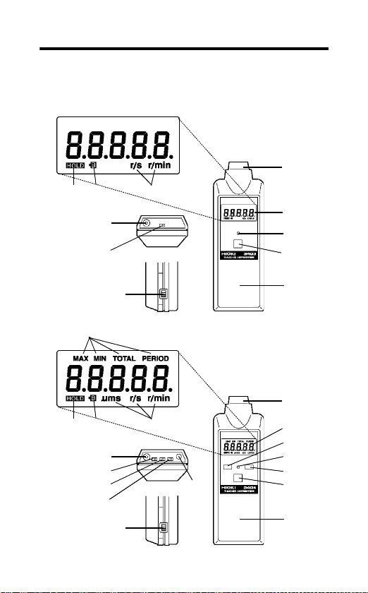
1.2 Names and Functions of
Parts
3403
(2)
(7) (8) (9)
(10)
(11)
(3)
(4)
(5)
(1)
(14)
(6)
3404
(2)
(7) (8) (9)
(10)
(15)
(11)
(16)
(1)
(17)
(3)
(12)
(4)
(13)
(5)
(6)
____________________________________________
Chapter 1 Overview
Page 15

____________________________________________
(1) Power switch Turn to ON for measurement.
(2) Photoelectric
Detection
Window
(3) Display Displays digital values.
(4) Reflected light
verification LED
HOLD
(5)
(6) Buzzer Sounds when reflected light is
(7) HOLD mark Lights when in a HOLD
(8) Battery low
(9) Unit symbols Indicates unit symbols.
(10) AC adapter
(11) r/min,r/s switch Used to select r/min
(12)
(13)
mark
jack
RESET
MODE
switch
switch
switch
Contains the light emitter and
receiver devices.
Lights when the instrument is
detecting reflected light.
Holds the current measured
value.
detected (can be set not to
buzz).
condition.
Lights when battery
replacement is needed.
Used to connect an AC
adapter (300 mA/6 V, 5 mm
dia)
(revolutions per minute) or r/s
(revolutions
per second).
Resets (initializes) at the
measurement mode.
Used to select measurement
mode.
11
____________________________________________
Chapter 1 Overview
Page 16

12
____________________________________________
(14) MODE symbols
(15) FAST/SLOW
mode switch
(16) Analog output
range switch
(17) OUTPUT
terminal
MAX
MIN
TOTAL
PERIOD
Holds maximum reading
Holds minimum reading
Total amount of rotations
Period of rotation measurement
Selects the sampling period.
Selects between x 0.1 (mV)
and x 0.01 (mV) for r/min
measurement and selects
between x 10 (mV) and x 1
(mV) for r/s measurement.
Used to connect a recorder or
other equipment with a 9094
OUTPUT CORD.
____________________________________________
Chapter 1 Overview
Page 17

____________________________________________
13
Chapter 2
Measurement Method
2.1 Measurement Preparations
1. If this is the first time the instrument
will be used, insert the batteries.
2. Attach the reflective tape to the
rotating object.
Before attaching the tape, make sure
that the surface of the object is free of
dirt, grease or dust.
3. Turn on the power switch, and check
that all segments of the display light
for about one second.
If the mark lights, replace the
batteries.
4. Turn the detector window so that the
red emitted light faces the reflective
tape on the rotating object. If the
reflected light is being detected, the
buzzer sounds and the LED lights.
If the reflectivity of the rotating object
itself is high and light is reflected from
portions other than the reflective tape,
tilt the instrument to restrict the
incident light and obtain a more
accurate reading.
____________________________________________
Chapter 2 Measurement Method
Page 18

14
____________________________________________
NOTE
The red light from the instrument shall
strike the reflective tape at an incidence
angle of 45 degrees or less. If the
incidence angle exceeds 45 degrees,
the instrument may not be able to
detect the reflected light and may not
be able to do measurement.
Incidence angle
Red light
Reflective tape
____________________________________________
Chapter 2 Measurement Method
Page 19

____________________________________________
15
2.2 Normal Measurement
1. When the power is turned on, the
instrument will automatically enter the
normal measurement mode.
2. The speed of rotation of the object will
be measured and displayed.
The speed of rotation range can be
switched between r/min and r/s during
measurement. The 3404 can also be
switched between FAST and SLOW
sampling period.
On the 3403, the last digit of the
display will be fixed to 0 for counts
over 20,000.
Analog output on the 3404 will match
the displayed value.
For speed of rotation measurement
under 30 r/min in the 3404 SLOW
mode or on the 3403 or for
measurement under 120 r/min in the
3404 FAST mode, the display will
appear as indicated right.
The display will appear as "
measurement over 100,000 r/min.
____________________________________________
Chapter 2 Measurement Method
-----
" for
Page 20

16
____________________________________________
NOTE
When the count exceeds 20,000 on the
3404 in the SLOW mode, the last digit
will be fixed to zero, and, in the FAST
mode the last two digits will be fixed to
zero. This is the same for MIN and MAX
hold modes as well.
During r/s measurements, accuracy of
values greater than 1600 r/s is not
assured.
2.3 MAX Hold Measurement
(3404 only)
Press the
mode.
In this mode, like the normal
・
measurement, the speed of rotation is
measured and the maximum detected
value is displayed where there is
variation in the speed of rotation.
Measurement may be freely switched
・
between r/min and r/s.
Pressing the
・
mode will clear the displayed
maximum value.
MODE
switch to enter the MAX
RESET
switch in this
____________________________________________
Chapter 2 Measurement Method
Page 21

____________________________________________
17
2.4 MIN Hold Measurement
(3404 only)
MODE
switch to enter the MIN
switch and begin measurement.
RESET
switch in this mode
NOTE
Press the
mode.
In MIN hold measurement, verify that
the detection LED is lit, and then press
RESET
ln this mode, like the normal
measurement, the speed of rotation is
measured, and the minimum detected
value is displayed where there is
variation in the speed of rotation.
Pressing the
will clear the displayed minimum value.
Measurement may be freely switched
between r/min and r/s.
Cautions in MAX and MIN hold measurement
Do not switch between FAST and SLOW
measurement modes during
measurement of MAX or MIN hold. If the
instrument is switched between FAST
and SLOW modes, press the
switch and begin measurement again.
RESET
____________________________________________
Chapter 2 Measurement Method
Page 22

18
____________________________________________
The analog output during MAX and MIN
hold measurement is independent of the
displayed values, and always represents
the normal measurement value.
The displayed maximum and minimum
values will be cleared with the
switch only. The maximum and
minimum values won't be cleared by
changing the mode with the
switch.
The maximum and minimum values will
continue to be updated even after
moving to another mode.
RESET
MODE
2.5 TOTAL Measurement
(3404 only)
Measurement in this mode is different
from normal mode measurement in that
pulses are simply counted, and the total
displayed.
MODE
1. Press the
TOTAL mode.
2. It will be 5 digit display. Displays of
measurement values of 100,000 and
higher use a decimal point code
system, where the actual value =
(number of decimal points) x 100,000
____________________________________________
Chapter 2 Measurement Method
+ displayed value.
switch to enter the
Page 23

____________________________________________
19
<For example>
3 x 100,000 + 83201 = 383201
NOTE
When the count exceeds 600,000, the
display shows "
" and the instrument
-----
stops counting.
The counting will continue inside the
instrument, even after the
HOLD
switch
is pressed.
The measurement value is cleared by
pressing the
RESET
switch.
Application example
Reflective tape
Reflective
Rotating body
Total rotations of the object
in a certain period of time
surface
Counting cartons passing
on a belt conveyer
____________________________________________
Chapter 2 Measurement Method
Page 24

20
____________________________________________
2.6 PERIOD Measurement
(3404 only)
In this mode the time of the rotation
pulse (period) is measured.
1. Press the
PERIOD measurement.
2. For measurement of 2 s and longer,
the display will appear as shown
below.
NOTE
____________________________________________
Chapter 2 Measurement Method
During PERIOD measurements,
accuracy of values less than 600μsis
not assured.
For the PERIOD measurement, two
sampling modes; FAST and SLOW are
available. In the FAST mode, the last
digit of the display will be fixed to zero.
MODE
switch to start
Page 25

____________________________________________
21
Cautions in TOTAL and PERIOD measurement
ln TOTAL and PERIOD measurement
the measurement value is displayed
regardless of changes to r/min/r/s.
During the TOTAL and PERIOD
measurement, the analog output will
be based on results of the NORMAL
measurement, regardless of the
current display.
The TOTAL measurement counting will
continue even after moving to another
mode.
____________________________________________
Chapter 2 Measurement Method
Page 26

22
____________________________________________
2.7 FAST/SLOW Mode
Measurement (3404 only)
The FAST/SLOW mode, switch selects
different sampling periods for
measurement and display. The sampling
period of the analog output is also
changed.
NOTE
Number of
Do not switch between FAST and
SLOW modes during measurement in
the MAX and MIN measurement mode.
If the mode is switched, press the
RESET
switch and restart measurement.
The display for TOTAL is not affected
by the FAST/SLOW mode switch
operation.
During the PERIOD measurement, the
last digit of the display will be fixed to
zero in the FAST mode.
FAST/SLOW mode display
rotating
(r/min)
625.4
1234.5
5421
15432
65878
SLOW
display
(r/min)
1234.5
6587
625.4
5421
15432
Accuracy
(r/min)
±0.1
±0.2
0
: indicates digits fixed to 0.
0
display
±1
±2
±10
FAST
(r/min)
625.
1234.
542
1543
658
0 0
Accuracy
0
0
0
0
(r/min)
±2
±4
±20
±40
±200
____________________________________________
Chapter 2 Measurement Method
Page 27

____________________________________________
23
2.8 Data Hold
This is used to freeze (hold) a displayed
value when it is difficult to read the
display.
HOLD
switch is pressed, the
NOTE
When the
display will be held, and also be
suspended. Pressing it for a second time
will release the hold.
Data hold is valid in all measurement
modes.
____________________________________________
Chapter 2 Measurement Method
Page 28

24
____________________________________________
2.9 Buzzer Off Set
Turn on the power while holding the
HOLD
switch down.
NOTE
Keep the HOLD switch depressed until
all the LCD indications light up and then
go out (about one second).
____________________________________________
Chapter 2 Measurement Method
Page 29

____________________________________________
25
Chapter 3
Precautions
Precautions in Measurement of
High-Rotation Objects
Detection of reflected light uses
modulated light to minimize the effects of
incident light. When this modulated light
is input for a fixed period of time (about
0.2 ms) or longer, a single pulse is
detected. For this reason, if the light
pulse generated by the passing reflective
tape is less than 0.2 ms detection is not
possible.
The range that can be detected with a
12 mm square target of reflective tape is
indicated below.
Radius is the distance between the center
of the rotating object and the center of the tape.
Radius
(mm)
60
60
40
20
11 5 10 (×10
Rotation (r/min)
The area of the reflective tape.
10
6
4
)
Radius
Rotating
body
Reflective tape
Center
____________________________________________
Chapter 3 Precautions
Page 30

26
____________________________________________
If the reflective tape cannot be attached
within this detection range, increase the
area of the reflective tape so that the
generated pulse is 0.2 ms or higher.
Attach reflective tape
Area where reflective tape
cannot be attached
Rotating body
For measurement of 30,000 r/min or
higher, use the following method:
Rotating body
Reflective portion
Area where light reflects
Non-reflective portion
NOTE
The red light from the instrument should
be adjusted slightly off center as shown,
not to the center of the rotating body.
____________________________________________
Chapter 3 Precautions
Page 31

____________________________________________
27
Chapter 4
Analog Output
(3404 only)
CAUTION
Do not input an external voltage to the
analog output terminal.
AC adapter jack
FAST/SLOW r/min, r/s Analog output range
1. Attach reflective tape to the rotating
body.
2. Connect the recorder and OUTPUT
terminal with the 9094 OUTPUT
CORD (comes with instrument).
3. Set sampling speed to FAST or
SLOW, and range to r/min or r/s.
4. Select the analog output magnification
to suit maximum r/min and recorder
range conditions.
5. Turn on power switch.
6. Check that the output is O where
there is no rotation being detected.
7. Output the red light from the
instrument detector window toward the
reflective tape on the rotating object.
OUTPUT terminal
9094 OUTPUT CORD
Recorder
____________________________________________
Chapter 4 Analog Output (3404 only)
Page 32

28
____________________________________________
Analog output
magnification
r/min X 0.1 (mV)
X 0.01 (mV)
r/s X 10 (mV)
X 1 (mV)
Measurement range
output range
30 to 10000 r/min 3 to 1000 mV
100 to 100000 r/min
0.5 to 100 r/s 5 to 1000 (mV)
1 to 1000 r/s
1to1000mV
1 to 1000 (mV)
Analog output is the conversion of the
displayed rotation speed to mV,
multiplied by the selected
magnification.
Minimum resolution for analog output
is 1 mV, regardless of range. In other
words, in the x 0.1 mV magnification
analog output is in 10 r/min steps; and
in the x 0.01 mV magnification, it is in
100 r/min steps. in the x 10 mV
magnification, analog output is in 0.1
r/s; and in the x 1 mV magnification, it
is in 1 r/s steps.
Analog output will convert measured
results for each sample (D/A) for
stable output even at low rotation
speeds. The sampling rate will be
changed when the measurement is
switched between FAST and SLOW
modes, allowing the optimum mode for
specific applications to be selected.
Sampling is 0.7 to 2.0 s in the SLOW
mode, and 0.12 to 0.5 s in the FAST
mode.
In r/s measurement, maximum output
is 1000 r/s, as even in the x 1 mV
____________________________________________
Chapter 4 Analog Output (3404 only)
range full scale output is 1 V.
Page 33

____________________________________________
29
The analog output is sent out during
the NORMAL, MAX HOLD and MIN
HOLD measurement. During the
TOTAL and PERIOD measurement,
the analog output will be based on
results of the NORMAL measurement.
When using the MAX, MIN and
HOLD
measuring features, the output level is
not held constant, but remains the
same as during normal measuring.
The analog output uses the current
measurement, not the held data,
during the DATA HOLD.
____________________________________________
Chapter 4 Analog Output (3404 only)
Page 34

30
____________________________________________
____________________________________________
Chapter 4 Analog Output (3404 only)
Page 35

____________________________________________
31
Chapter 5
Measurement with 9213
CONTACT ADAPTER
9213 CONTACT ADAPTER
Contact tip
Screw
Main body
Rotating body
1. Attach the contact adapter over the
detector window with the "up" mark
facing up. Tighten it with a screwdriver
on both sides.
2. Turn on the power, and rotate the
contact tip manually. Check that the
buzzer sounds and the LED lights.
3. For rotation speed measurement,
insert the shaft of the 9033 RUBBER
CONTACT TIP or 9032 METAL
CONTACT TIP (used with soft rotating
objects).
4. Lightly press the contact tip against
the center of the rotating body.
____________________________________________
Chapter 5 Measurement with 9213 CONTACT ADAPTER
Belt conveyer measurement with
peripheral ring
Peripheral ring
Page 36

32
____________________________________________
5. Insert the 9212 PERIPHERAL RING
onto the adapter for measurement of
period, such as for a belt conveyer.
For r/min mode measurement, the
display reading is multiplied by 0.1,
read in m/min.
For r/s mode measurement, the
display reading is multiplied by 0.1,
read in m/s.
NOTE
Do not use with rotating bodies that do
not have dent in the center.
____________________________________________
Chapter 5 Measurement with 9213 CONTACT ADAPTER
Page 37

____________________________________________
33
Chapter 6
Specifications
Measurement
method
Display LCD 4 1/2 digits (5 digits with the
Display marks
Range select Automatic
Sampling
period
Data hold Fixes the display when the hold
Over range
display
MAX, MIN
hold
Detection
distance
Reflected light
detection
confirmation
Visible light reflection
last digit fixed at 0 for 20, 000 r/min
and higher)
TOTAL measurement: 5 digits (3404
only)
, r/min, r/s, and marks
HOLD
(MAX, MIN, TOTAL, PERIOD, μs,
ms, s (3404 only))
0.5 to 2.0 s (SLOW mode and on
the 3403)
0.1 to 0.5 s (on the 3404 FAST
mode)
switch is used.
Displays "-----"
Holds maximum or minimum value
display (3404 only)
50 to 200 mm (1.97" to 7.87")
Buzzer and LED
____________________________________________
Chapter 6 Specifications
Page 38

34
____________________________________________
Accuracy
Tripod
mounting
Operating
temperature/
humidity
Storage
temperature/
Display
4digits
4 1/2 digits
20,000 and
over.
Tripod mounting bolt provided on
body
0to40 (32 to 104 ),
80% RH or less (no condensation)
-10 to 50 (14 to 122 ),
80% RH or less (no condensation)
3403,
3404(SLOW)
1dgt.
±
2dgt.
±
10 dgt.
±
3404(FAST
20 dgt.
±
40 dgt.
±
200 dgt.
±
)
humidity
Power supply Rated supply voltage: 6.0 VDC
Regulated power supply range:
6.0 V or later (until the
lights up)
mark
Four R6P manganese batteries
Continuous
measurement
3403: approx. 17 h
3404: approx. 16 h
time
AC adapter 6 V / 300 mA : 5 mm dia
Maximum
rated power
Dimensions
and mass
0.4 VA
Approx. 62W x 182H x 38D mm
(2.44"W x 7.17"H x 1.50"D)
Approx. 260 g (9.2 oz.)
____________________________________________
Chapter 6 Specifications
Page 39

____________________________________________
35
Standards
Safety
EN61010
Pollution Degree 2, Overvoltage
Category I (anticipated transient
overvoltage 330 V)
EMC
EN61326
Accessories 9211 REFLECTIVE TAPE
9094 OUTPUT CORD
Carrying case
Four R6P manganese batteries
Instruction manual
Option 9211 REFLECTIVE TAPE
9035 AC ADAPTER
9094 OUTPUT CORD
9213 CONTACT ADAPTER
the 9032, the 9033 (two), the 9212,
screwdriver)
(1 sheet)
(3404 only)
(10 sheets)
(no CE marking)
(includes
9213
9032 9033 9212
____________________________________________
Chapter 6 Specifications
Page 40

36
____________________________________________
Analog output (3404 only):
DC, Max. 1 V, Min. resolution 1 mV
Analog output
magnification
r/min X 0.1 (mV)
X 0.01 (mV)
r/s X 10 (mV)
X 1 (mV)
Measurement range
output range
30 to 10000 r/min 3 to 1000 mV
100 to 100000 r/min
0.5 to 100 r/s 5 to 1000 mV
1 to 1000 r/s
(Accuracy
1to1000mV
1 to 1000 mV
1%rdg. 1mV,
Output resistance: 1 kΩ)
Measurement range:
<Non-contact type>
NORMAL, MAX, MIN
(In SLOW mode and on the 3403)
30 to 99990 r/min, 0.5 to 1600 r/s
r/min r/s
Range 30.00
to
199.99
200.0
to
1999.9
2000
to
19999
2000
to
9999
0
0
0
: indicates digits fixed to 0.
0.5000 to 1.9999
2.000 to 19.999
20.00 to 199.99
200.0 to 1600.0
(In FAST mode on the 3404 only)
120 to 99900 r/min, 2 to 1600 r/s
r/min r/s
Range 120.0
200
____________________________________________
Chapter 6 Specifications
200.
200
to
1999.9
0 0
0
to
0
to
0
to
0
0
1999.
1999
999
0
0
200.00to 160.0
0 0
2.000to 19.99
20.00to 199.9
: indicates digits fixed to 0.
0
0
0
Page 41

____________________________________________
37
TOTAL (3404 only): 0 to 599999, 5 digit
display (decimal point used for 100,000
counts and higher)
Display Measurement range
Range 00000
000.0.0.
00.0.0.0.
0.0.0.0.0.
00000.
0000.0.
to
to
to
to
999.9.9.
to
99.9.9.9.
to
9.9.9.9.9.
99999
99999.
9999.9.
(100000
(200000
(300000
(400000
(500000
(0
to
to
199999)
to
299999)
to
399999)
to
499999)
to
599999)
99999)
PERIOD (3404 only): 600 μs to 1.9999 s
(SLOW), 600 μs to 500 ms (FAST)
SLOW FAST
Range 600.0
1.0000
2.000
20.00
200.0
1.0000
to
999.9 μs
to
1.9999 ms
to
19.999 ms
to
199.99 ms
to
999.9 ms
to
1.9999 s
600.
to
999.
0
2.00
20.0
200.
to
0
to
0
to
0
to
0
1.000
: indicates digits fixed to 0.
0
1.999
19.99
199.9
500.
0 μs
0
0
0
0
ms
ms
ms
ms
<Contact type>
NORMAL, MAX, MIN
(in SLOW mode and on the 3403): 30 to
20000 r/min, 0.5 to 333 r/s
(in FAST mode on the 3404 only): 120 to
20000 r/min, 2 to 333 r/s
____________________________________________
Chapter 6 Specifications
Page 42

38
____________________________________________
____________________________________________
Chapter 6 Specifications
Page 43

____________________________________________
39
Chapter 7
Maintenance and
Service
7.1 Battery Replacement
WARNING
To avoid electric shock when replacing
the batteries, first disconnect the output
cord and AC adapter.
Do not mix old and new batteries, or
different types of batteries. Also, be
careful to observe battery polarity during
installation. Otherwise, poor performance
or damage from battery leakage could
result.
Battery may explode if mistreated. Do not
short-circuit, recharge, disassemble or
dispose of in fire.
Handle and dispose of batteries in
accordance with local regulations.
NOTE
____________________________________________
To avoid corrosion from battery
leakage, remove the batteries from the
instrument if it is to be stored for a long
time.
Chapter 7 Maintenance and Service
Page 44

40
____________________________________________
When the lights on the display, slide
open the cover and replace the batteries.
7.2 Maintenance
To clean the instrument, wipe it gently
with a soft cloth moistened with water or
mild detergent. Never use solvents such
as benzene, alcohol, acetone, ether,
ketones, thinners or gasoline, as they
can deform and discolor the case.
7.3 Service
If the instrument seems to be
malfunctioning, confirm that the batteries
are not discharged before contacting
your dealer or Hioki representative.
Pack the instrument so that it will not
sustain damage during shipping, and
include a description of existing damage.
We do not take any responsibility for
damage incurred during shipping.
____________________________________________
Chapter 7 Maintenance and Service
Page 45

Page 46

Page 47

HIOKI 3403, 3404 TACHO HiTESTER
Instruction Manual
Publication date: July 2008 Revised edition 2
Edited and published by HIOKI E.E. CORPORATION
Technical Sales Support Section
All inquiries to International Sales and Marketing
Department
81 Koizumi, Ueda, Nagano, 386-1192, Japan
TEL: +81-268-28-0562 / FAX: +81-268-28-0568
E-mail: os-com@hioki.co.jp
URL http://www.hioki.com/
Printed in Japan 3403A981-02
・ All reasonable care has been taken in the production of
this manual, but if you find any points which are
unclear or in error, please contact your supplier or the
International Sales and Marketing Department at HIOKI
headquarters.
・ In the interests of product development, the contents of
this manual are subject to revision without prior notice.
・ The content of this manual is protected by copyright.
No reproduction, duplication or modification of the
content is permitted without the authorization of Hioki
E.E. Corporation.
Page 48

HEAD OFFICE
81 Koizumi, Ueda, Nagano 386-1192, Japan
TEL +81-268-28-0562 / FAX +81-268-28-0568
E-mail: os-com@hioki.co.jp/
URL http: //www.hioki.com/
HIOKI USA CORPORATION
6 Corporate Drive, Cranbury, NJ 08512, USA
TEL +1-609-409-9109 / FAX +1-609-409-9108
3403A981-02 08-07H
Printed on recycled paper
 Loading...