

Page 1
Introduction
Before using the pr oduct the firs t time, verify th at it operates
normally to ensure th at the no dam age occu rred during stor-
age or shipping. If you find any damage, contact your dealer
The clamp sensor or the case shall b e free of damage. (If
avoid using the product. Use of the
The mating portions of the clamp sensor should be free of
Battery power should be near full capacity when power is turned
The reading should be around 0 A us ing the curr ent functi on
3293-50
CLAMP ON LEAK HiTESTER
Instruction Manual
January 2012 Revised edition 1
Printed in Japan
3293C981-01 12-01H
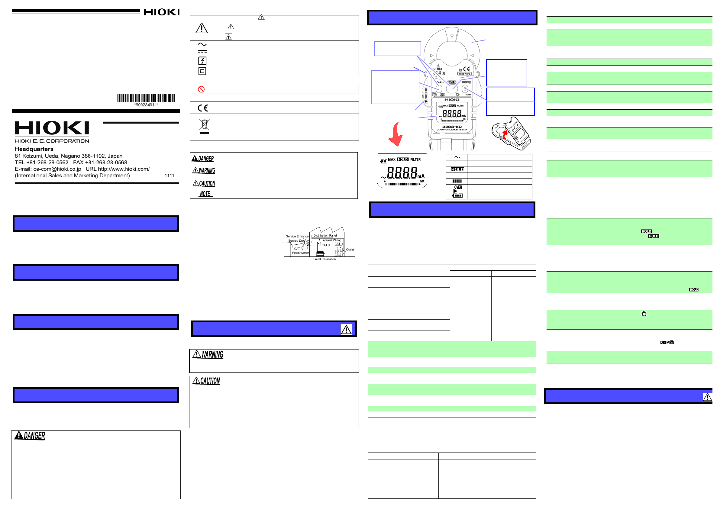
Clamp Sensor
Barrier
Lever
Display (LCD)
Press Once
Press 2 sec.
• Data Hold
• Back Light
PRESS Once
PRESS 2 sec.
• Digital Display
• Filter OFF/ON
Press Once
Press 2 sec.
• Maximum Data
• Power OFF
(Magnified View)
Alternating current (AC)
MAX MAX value
Data hold function
FILTER Filter ON
Bar graph
Over range
Battery low warning (4 levels)
* The device considers the maximum
displayed value to be the MAX value.
Press both
• Clear MAX value
• I
nstantaneous
value
Altitude up to 2000 m (6562 feet)
5 mA sensitivity current between the chassi s and clamp core
when the power supply is
ress the MAX key and
x.10 minutes.
Thank you for purchasi ng the HIOK I Model 3293-50 CLAMP ON LEAK
HiTESTER. To obta in ma ximu m perform ance from the pro duct, pl ease
read this manual first, and keep it handy for future reference.
Overview
The 3293-50 Clamp On Lea k HiTester is a small sized, thi n-type sensor
that can measure cu rrent betw een a wide 1 mA to 1000 A range. In a ddition, the angle of the display panel can be adjusted to suit the measuring location, and th e back light m akes the produ ct eas y to use even
in dark places.
Inspection
Initial Inspection
When you receive the product, inspect it carefully to ensure that no
damage occurred during shipping. If damage is evident, or if it fails to
operate according to the specifications, contact your dealer or Hioki
representative.
Maintenance and Service
• To clean the product, wipe it gently with a soft cloth moistened with
water or mild detergent. Never use solvents such as benzene, alcohol, acetone, ether, ketones, thinners or gasoline, as they can
deform and discolor the case.
• If the protective functions of the product are damaged, either
remove it from service or mark it clearly so that others do not use it
inadvertently.
• If the product seems to be malfunctioning, contact your dealer or
Hioki representative.
Safety
This manual contains information and warnings essential for
safe operation of the product and for maintaining it in safe operating condition. Before using it, be sure to carefully read the following safety precautions.
This product is designed to comply with IEC 61010 Safety
Standards, and has been thoroughly tested for safety
prior to shipment. However, mishandling during use
could result in injury or death, as well as damage to the
product. However, using the product in a way not
described in this manual may negate the provided safety
features. Be certain that you understand the instructions
and precautions in the manual before use. We disclaim
any responsibility for accidents or injuries not resulting
directly from product defects.
Safety Symbol
In the manual, the symbol indicates particularly important
information that the user should read before using the instrument.
The symbol printed on the instrument indicates that the user
should refer to a corresponding topic in the manual (marked with
the symbol) before using the relevant function.
Indicates AC (Alternating Current).
Indicates DC (Direct Current).
Indicates that the instrument may be connected to or disconnected
from a live circuit.
Indicates a double-insulated device.
Other Symbols
Indicates a prohibited action.
Symbols for Various Standards
This symbol indicates that the product conforms to safety regulations set out by the EC Directive.
WEEE marking:
This symbol indicates that the electrical and electronic appliance is
put on the EU market after August 13, 2005, and producers of the
Member States are required to display it on the appliance under
Article 11.2 of Directive 2002/96/EC (WEEE).
The following symbols in this manual indicate the relative importance
of cautio ns and warnings.
Indicates that incorrect operation presents an extreme hazard
that could result in serious injury or death to the user.
Indicates that incorrect operation presents a significant hazard
that could result in serious injury or death to the user.
Indicates that incorrect operation presents a possibility of
injury to the user or damage to the device.
Indicates advisory items related to pe rform ance or correct op erati on of
the product.
Measurement categories
This product complies with CAT III 300 V safety requirements. To ensure safe
operation of measurement products, IEC 61010 establishes safety standards
for various electrical environments, categorized as CAT II to CAT I V, and called
measurement categories.
CAT II: Primary electrical circuits in
equipment connected to an AC
electrical outlet by a power cord
(portable tools, household appliances, etc.)
CAT II covers directly measuring
electrical outlet receptacles.
CAT III: Primary electrical circuits of
heavy equipment (fixed installations) connected directly to the distribution panel, and feeders from the
distribution panel to outlets.
CAT IV: The circ uit fro m the serv ice drop to the service entran ce, and t o the po wer
meter and primary over curre nt protec tio n device ( distribu ti on p anel ).
Using a measurement product in an environment designated with a highernumbered category than that for which the product is rated could result in a
severe accident, and must be carefully avoided.
Use of a measurement instrument that is not CAT-rated in CAT II to CAT IV
measurement applications could result in a severe accident, and must be carefully avoided.
Usage Notes
Follow these precautions to ensu re safe operation an d to obtain the full
benefits of the various functions.
Do not allow the product to get wet, and do not take measurements with wet hands. This may cause an electric shock.
• Do not store or use the product where it could be exposed to
direct su nlight, high temperature or humidity, or condens a tion.
Under such cond itions, the product m ay be dam aged and insu lation may deteriorate so that it no longer meets specifications.
• This instrument contains a magnetic core. The device
should not be used by anyone with a pacemaker or any other
electronic medical devic es install ed in his body.
Names and Functions of Parts
Specific ations
Measurement specification
• Temperature and humidity for guaranteed accuracy: 23±5°C (73±9°F),
80%RH or less.
• Guaranteed accuracy period: 1 year, or opening and closing of the
Clamp Sensor 10,000times, whiche ve r com es firs t.)
• Guaranteed accuracy range: 1.00 mA or above
AC current A rms (true rms indication, Auto range)
0.05 mA or less zero-suppression
Range
30 mA
300 mA
6 A
60 A
600 A
1000 A
Effect of conductor
position
Maximum rated voltage
to earth
Crest factor
Diameter of measurable
conductor
Temperature coefficient
Magnetic field
interference
Response time :1.1 sec.
Maximum input current
We define measurement tolerances in terms of rdg. (reading) and dgt. (digit) values, with the following meanings:
rdg. (reading or displayed value)
The value currently being measured and indicated on the measuring product.
dgt. (resolution)
The smallest displayable unit on a digital measuring product, i.e., the input value
that causes the digital display to show a "1" as the least-significant digit.
Accuracy spec :±1.5%rdg. ±5dgt.
Measurement range
Measurement values
Guaranteed
accuracy
1.00 mA to 30 . 00
mA
27.0 mA
to 300.0 mA
0.270 A
to 6.000 A
5.40 A
to 60.00 A
54.0 A
to 600.0 A
540 A
to 1000 A
Example Calculation
:60.00 A
:30.00 A
Resolution
0.01 mA
0.1 mA
0.001 A
0.01 A
0.1 A
1 A
:Within ±0.1% (up to 6 A range), Within±5.0%
(greater than 60 A range)
(in any position based on the center of the clamp sensor)
: 300 Vrms, Measurement category III
(anticipated transient overvoltage 4000 V)
: 2.8 or less (up to 600 A), 1.68 or less (1000 A range)
:
24 mm dia. or less
:Within 0.05 × precision specification / °C
Other than 23°C±5°C (73
: Maximum 7.5 mA in an external magnetic field of
AC 60 Hz 400 A/m (
:1000 A (Refer to Fig. 1)
(A)
(B)
(C)Total error: (A)+(B) = ± 0.50 A
FILTER ON FILT ER OFF
±1.5%rdg. ±5dgt.
(50 Hz to 60 Hz)
or less
Reading error (± %rdg.): ± 1.5% of 30.00 A =
± 0.4 5 A
Digit error (± dgt.): ± 5dgt. =± 0.05 A (Due to
minimum resolution of 0.01 A)
The limit error value for the measured value of
30.00 A is 29.50 A ~ 30.50 A based on the total
error (C).
up to
Accuracy
°F±9°F
)
6 A range)
±1.5%rdg. ±5dgt.
(45 Hz to 66 Hz)
±3.0%rdg. ±5dgt.
(66 Hz to 40 0 Hz)
General Specifications
Display update rate 1.1 sec. or less
Display LCD: monochrome, 91 segments
Operating
temperature and
humidity
Storage temperature
and humidity
Location for use
Rated supply voltage 3 VDC × 1
Maximum rated
power
Power supply CR2032 x 1 Lithium battery
Battery li fetime
Dimensions
Mass Approx. 135 g (4.8 oz.)
Dielectric strength
Applicable standards
Accessories
0 to 40°C (3 2 to 10 4°F ), 8 0% RH o r le ss
(with no condensation)
-10 to 50°C
(
with no condensation
Indoors, Po llu tio n degr e e 2,
25 mVA
Approx.18 hours
(continuous, no load, at
Approx. 50W × 130H × 26D mm (1.97”W×5.12”H×1.02”D)
3536 Vrms /15sec.
Safety EN61010
EMC EN61326
9757 Carrying Case, Strap, Instruction Manual,
CR2032 Lithium battery
(14.0 to 122.0°F), 80%RH or less
)
23°C
)
Functions
Power supply control
Filter
Data hold
MAX value display
Auto power-off
Battery Level
Indicator
Back light
Liquid crystal display
(LCD) reversal
Bar graph
Over range display
ON : Grasping the lever and opening wide the Clamp
Sensor (sideways).
OFF: Press POWER OFF key for 2 seconds or longer .
Details of operation
Cutoff frequency :180 Hz±30 Hz (-3dB)
Initial setting: ON (Always ON
turned on; non-filtered data is not saved)
Activate/De-activate: Press FILTER key for 2 seconds
or longer.
*When set to ON, the filter removes noise and other
unwanted frequency components.
Details of operation: Holds measured values (data
update is halted)
Activate:
Pres sing the key once.
De-activate:Pres s ing th e key once.
Details of operation: Displays the maximum measured
values reached since the power has been turned on.
Activate/De-activate: Pressing the MAX key once.
Clear displayed maximum value: P
HOLD key at the same time. Filter OFF/ON
Details of operation: The power cuts off when "0" is
displayed continuously for 1 minute.
Any key operation is not p erf orme d fo r app ro
To de-activate: Power ON while pressing the key.
Details of operation: Displays 4 levels of remaining
battery charge.
*Refer to “Replacing Battery”.
Setting
method: Press key for 2 s
(About 15 seconds lighting.)
*Frequent use of backlight reduces battery life.
Details of operation: Automatically reverses when the
display panel is opened and closed.
Manual reversal: Pressing the key once.
*Refer to “Opening and Closing the Display Panel”.
Shows the proportion of the measured value to the
range.
Over-Range Display: Displays “OVER” when a high
crest factor current is inputted, which means an out of
the accuracy guarantee.
*Refer to “Crest factor”.
: Low pass filter OFF/ON
FILTER OFF/ON
econds or longer.
Measurement Procedure
Pre-Operation Inspection
(Check the following before using the product.)
•
or Hioki representa tive.
•
damage has occurred ,
product under these conditions may result in electric shock.)
•
any scratches or cracks.
•
on. (Refer to “R eplac ing Batte ry”.)
•
when no measurements are being made.
Page 2
• This product should only be connected to the second-
Fig 1. Maximum allowable current for frequency
Previous models
3293-50
OK
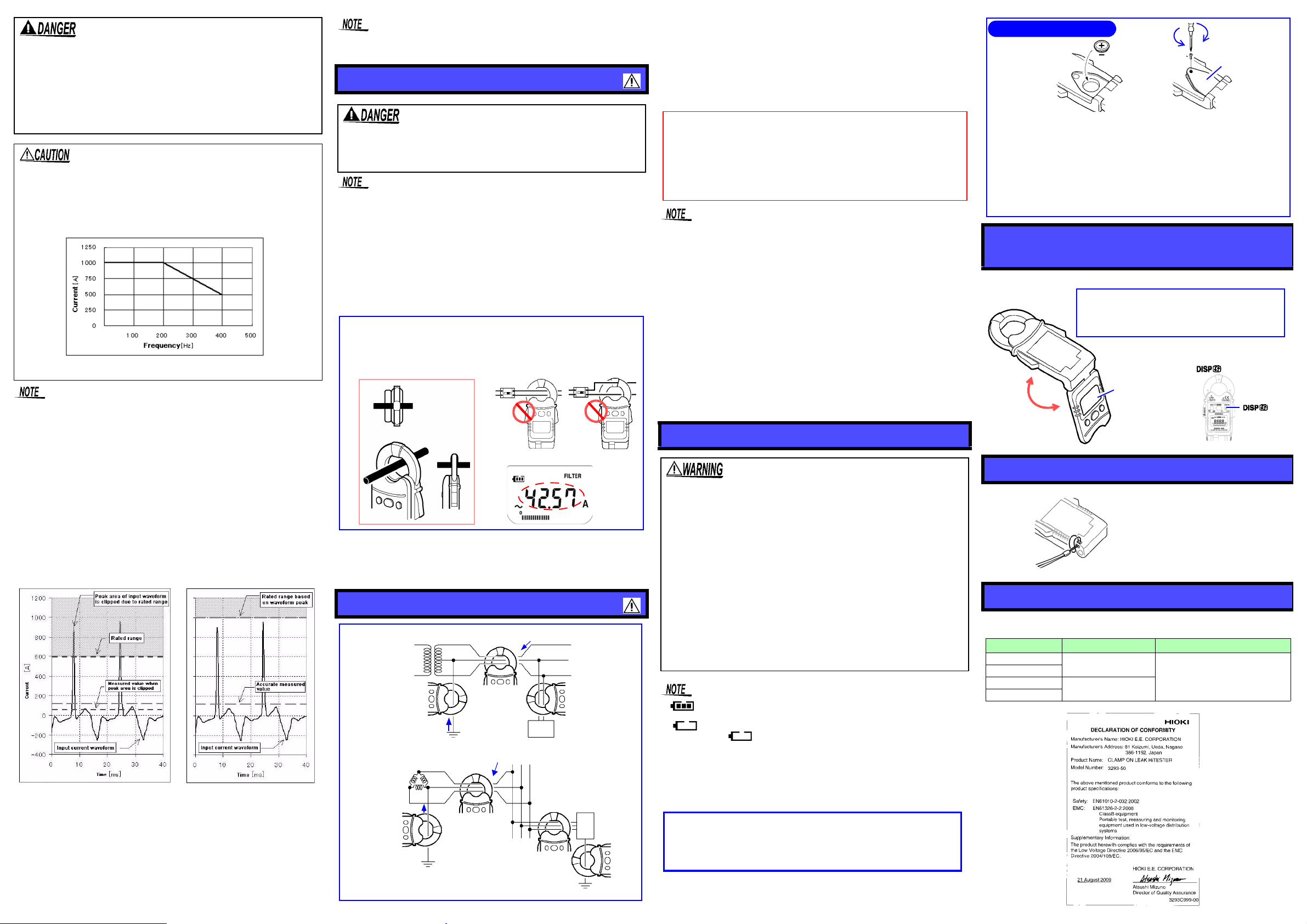
1. Clamp the tester on the conductor so that the conductor passes
through the center of the clamp core.
• Put the conductor perpendicular to the sensor, as shown in the sketch.
• Clamp the tester on one wire only.
2. The effective value is shown on the digital display.
Display example
single-phase 3-wire circuits
Transformer
lg
b
b
a
clamp all three wires of the circuit
Load
device
E(PE)
Load
lg
b
b
a
three-phase 3-wire circuits
clamp all three wires of the circuit
device
E(PE)
a
PE
Ig: lea k C ur ren t
Regarding the Auto Power Off Function
If the measured cu rrent rem ains at 0 am pere for 1 m inute or no k ey
is pressed for 10 minutes, power turns off automatically.
When measuring leakage current, if you wish to disable the Auto
Power Off function, turn the device's power on while pressing the
HOLD key. Press the POWER OFF key for 2 seconds or longer to
turn the device off.
CALIFORNIA, USA ONLY
This product contains a CR Coin Lith ium Battery w hich contain s
Perchlorate Material - special handling may apply.
See www.dtsc.ca.gov/hazardouswaste/perchlorate
Replacing th e Batteries
Battery cover
Position the battery
side is on top.
Tighten
Loosen
so that the plus (+)
1. Press and hold the POWE R OFF key for 2 seconds or
longer to turn off the device's power.
2.
Remove the battery cover sc rews on the back of the device
with a Phillips screwdriver, then remove the battery co ver.
3. Replace with a new battery. When inserting a new battery
(CR2032 lithium battery), be sure to position the polarities
in their proper orientations.
4. Replace the battery cover and fasten the screws.
The display can also be
key
Display Panel
the key.
Take measurements with the display panel flipped
open in order to view the measurement results
more clearly, especially in tight locati ons, without
needing to twist the jaw at an awkward angle.
reversed by pressing
Make the strap go through the
hole just like the Figure shown.
ary side of a breaker, so the breaker can prevent an
accident if a short circuit occur s. Connections should
never be made to the primary side of a breaker, because
unrestricted current flow could cause a serious accident if a short circuit occurs.
• To avoid electric shock, do not touch the portion
beyond the protective barrier during use.
• Be careful to avoid dropping the clamps or otherwise subjecting them to mechanical shock, the Clamp Sensor tip will
be damaged, negatively influencing measurement.
• Do not input a current e xceeding the maximum allowable
current. Doing so will make the clamp sensor generate heat,
which may damage the product and cause burn.
• Please note that waveforms that include elements outside the frequency
characteristic range may not be measured correctly.
• Accurate measurement may be impossible in the presence of strong
magnetic fields, such as near transformers and high-current conductors, or in the presence of st rong elec tro mag ne tic fiel ds s uch as near
radio tra nsmitters.
Crest factor
“Crest factor = Waveform peak value/ Internal rated range” is defined for this
instrument. There are cases when the accurate measurement c annot be performed with our previous models, because a top portion of the wavef orm is
clipped off due to the rated range if a high crest factor current (= RMS is low
and a waveform peak is high) is flowed. This inst rument defines the range
based on a waveform peak value and measured value so that the accurate
measurement can be performed. As for a high crest factor current , its measured value becomes small to the range. If a current exceeding a crest factor
of 2.8 is inputted, “OVER” is displayed. This measurement is the out of accu-
racy guarantee range and the measured value is for reference purpose only.
Regarding the MAX value display
(1) Press the MAX key once to confirm t he MAX value. If the MAX value is
renewed, the new value will be displayed as the MAX value. After
approximately 15 seconds the device will return will return to normal
measurement display and the MAX value will be saved.
(2) You can clear the MAX value by pressing the MAX key while the MAX value
is being displayed.
(3) When opening and closing the clamp sensor frequently, a large display
count may remain on the MAX value display. When measuring for the
maximum value, clamp onto the conductor and clear any residual
maximum values before conducting your test.
• As far as the Data Hold mode is on, MAX value can not be updated.
• The MAX value is cleared with FILTER OFF/ON.
AC Current Measurement
To avoid short circuits and potentially lif e-thr eat ening hazards, never attach the product in current measurement
mode to a circuit that operates at more than the maximum
rated voltage CAT III 300 V, or over bare conductors.
• Correct measurement may be impossib le for the cas e of rush cur rent
or significantly fluctuating current.
• As for the measurement on 6 A or more, the error margin might be
larger depending on the positioning of the conductor and sensor.
• When the measuring value exceeds 1000 A the digital display will
blink.
• Waveforms around 20 Hz or below may be displayed as “----”.
• At a low temperature, there are cases when the reading may not be
around 0 A without any input signal. But it does not affect measurement.
Open Jaws to Power On.
Filter function
(1) The default setting of Filter is ON. Please change the setting according to
the use.
(2) Normally, load current is measured with Filter OFF and leak current is mea-
sured with Filter ON.
Leak Current Measurement
1.Clamp the tester on the conductor, so that the conductor
passes through the center of the clamp sensor. For measurement of grounded wires, cla mp the tester on one wire only
(see a). For ove rall measurements, clamp the tester on the
entire circuit path (see b).
2.The effective value (RMS) of the leak current is shown on the
digital display. The selected current range is shown at the
bottom of the display.
• For measurement of single-phase 2-wire circuits, clamp both
wires of the circuit.
• For measurement of three-phase 4-wire circuits, clamp all four
wires of the circuit. If this is not possible, the measurement can
also be carried out on the ground wir e of the equipment.
• Do not input current that exceeds the maximum continuous
input of the electric current range.
• Meas urement may not be accurate in the cases below.
(1) When there is large current (of about 100 A) flowing through
a nearby electric line.
(2) When using the 3293-50 to measure special waveform s,
such as those on the secondary side of an inverter
• Note that a large display count may appear momen tly when
opening or closing the clamp sensor. This is not an error. It
may take some time for the display to return to zero. However,
starting measurement before the display returns to zero will
not affect measurement.
Replacing Battery
• To avoid electric sh ock when replacing the ba ttery first
disconnect the clamp from the object to be measured.
After replacing the batteries, replace the cover and
screws before using the product.
• Use only CR2032 lithium battery. Use of any other battery may result in explosion.
• Be sure to insert them w ith the correct polarity. Otherwise, poor performance or damage from battery leakage could result.
• Battery may explode if mistreate d. Do not short-circu it,
recharge, disassemble or dispose of in fire.
• Handle and dispose of batteries in accordance with
local regulations.
• Keep batteries away from children to prevent accidental
swallowing.
• To avoid corrosion from battery leakage, remove the batteries from the product if it is to be stored for a long time
• at the upper left on the display screen indicates the remaining
power level. When the battery approaches the exhausting value,
is displayed and a few minutes later, power turns off automatically. When is displayed, the accuracy of measurement value
is not guaranteed. Replace the new batteries soon.
• At a low or high temperature, the battery life is reduced faster.
• The batteries included with the device were installed for factory testing purpos es. CR2032 lithium batteries can be purchased at elec tronics and appliance stores where specialized batteries are sold.
Opening and Closing the
Display Panel
Adjust the angle of the display pane l for better viewing.
Attaching the strap
Fix the strap for fall prevention.
Error Display
When an error is displayed on the LCD, the HiTester requires
repair. Contact your supplier or Hioki representative.
Error Display
Err0
Err1
Err2
Err3
Meaning Remedial Action
Internal ROM Error
Calibration Data Faulty
Repair is necessary. Contact your
supplier or Hioki representative.
 Loading...