

Page 1
Warranty
3291-50
CLAMP ON HiTESTER
Instruction Manual
Aug. 2016 Revised edition 6
Printed in Japan
3291C981-06 16-08H
EN
Alternating current (AC)
MAX MAX value
Data hold function
FILTER Filter ON
Bar graph
Over range
Battery low warning (4 levels)
Jaws
Barrier
Lever
Display (LCD)
Press once
Press 2 sec.
Digital display
Filter OFF/ON
Press once
Press 2 sec.
Maximum data
Power OFF
(Magnified View)
* The device considers the maximum
displayed value to be the MAX value.
Press once
Press 2 sec.
Data hold
Back light
Press both
Clear MAX value
Instantaneous
value
Warranty malfunctions occurring under conditions of normal use in conformity with the Instruction Manual and Product Precautionary Markings will be repaired free of charge. This warranty is valid for a period
of one (1) year from the date of purchase. Please contact the distributor from which you purchased the product for further information on
warranty provisions.
Introduction
Thank you for purchasing the HIOKI Model 3291-50 CLAMP ON
HiTESTER. To obtain maximum performance from the instrument,
please read this manual first, and keep it handy fo r future reference.
Overview
Because it employs a small, thin-type sensor the 3291-50 Clamp On
HiTester can clamp even in narrow places. In addition, the ang le o f
the display panel can be changed to suit the measuring location and
the back light makes the instrument easy to use even in dark places.
Inspection
Initial Inspection
When you receive the instrument, inspect it carefully to ensure
that no damage occurred during shipping. If damage is evident,
or if it fails to operate according to the specifications, contact
your dealer or Hioki representative.
Maintenance and Service
• To clean the instrument, wipe it gently with a soft cloth moistened with water or mild detergent. Never use solvents such
as benzene, alcohol, acetone, ether, ketones, thinners or
gasoline, as they can deform and discolor the case.
• If the protective functions of the instrument are damaged, either
remove it from service or mark it clearly so that others do not
use it inadvertently.
• If the instrument seems to be malfunctioning, contact your
dealer or Hioki representative.
Safety
This manual contains information and warnings essential for
safe operation of the instrument and for maint aining it in safe operating condition. Before using it, be sure to carefully read the
following safety precautions.
This instrument is designed to comply with IEC 61010 Safety
Standards, and has been thoroughly tested for safety prior to
shipment. However, mishandling during use could result in
injury or death, as well as damage to the instrumen t. However,
using the instrument in a way not described in this manual may
negate the provided safety features. Be certain that you understand the instructions and precautions in the manual before
use. We disclaim any responsibility for accidents or injuries not
resulting directly from instrument defects.
Safety Symbol
Indicates cautions and hazards. When the symbol is printed on
the instrument, refer to a corresponding topic in the Instruction
Manual.
Indicates AC (Alternating Current).
Indicates DC (Direct Current).
Indicates that the instrument may be connected to or discon-
nected from a live circuit.
Indicates a double-insulated device.
Notation of the This Manual
Indicates a prohibited action.
Symbols for Various S tandards
This symbol indicates that the instrument conforms to regulations
set out by the EC Directive.
Indicates the Waste Electrical and Electronic Equipment Directive
(WEEE Directive) in EU member states.
The following symbols in this manual indicate the relative importance
of cautions and warnings.
Indicates that incorrect operation presents an extreme hazard
that could result in serious injury or death to the user.
Indicates that incorrect operation presents a significant hazard
that could result in serious injury or death to the user.
Indicates that incorrect operation presents a possibility of
injury to the user or damage to the device.
Indicates advisory items related to performance or correct
operation of the instrument.
Measurement categories
To ensure safe operation of meas uring instruments, IE C 61010 establishes safety standards for various electrical environments, categorized
as CAT II to CAT IV, and called measurement categories.
• Using a measuring instrumen t in an environment designated
with a higher-numbered category than that for which the
instrument is rated could result in a severe accident, and
must be carefully avoided.
• Using a measur ing instrument without categories in an environment designated with the CAT II to CAT IV category could
result in a severe accident, and must be carefully avoided.
This instrument complies with CAT III 600 V, CAT IV 300 V safety requirements.
CAT II:When directly measur ing the el ectrical outle t receptacles of the
CAT III:When measuring the primary electrical circuits of heavy equip-
CAT IV:When measuring the circuit from the service drop to the service
primary electrical circuits in equipment connected to an AC
electrical outlet by a power cord (portable tools, household appliances, etc.)
ment (fixed installations) connected directly to the distribution
panel, and feeders from the distribution panel to outlets
entrance, and to the power meter and primary overcurrent protection device (distribution panel)
Usage Notes
Follow these precautions to ensure safe operation and to obtain
the full benefits of the various functions.
Do not allow the instrument to get wet, and do not take
measurements with wet hands. This may cause an electric shock.
• Do not store or use the instrument where it could be exposed
to direct sunlight, high temperatur e or humidity, or condensation. Under such conditions, the instrument may be damaged and insulation may deteriorate so that it no longer
meets specifications.
• This instrument contains a magnetic core. The device
should not be used by anyone with a pacemaker or any other
electronic medical devices installed in his body.
Names and Functions of Parts
Specifications
Measurement specification
• Temperature and humidity for guaranteed accuracy: 23±5°C
(73±9°F), 80%RH or less.
• Guaranteed accuracy period: 1 year, opening and closing of
the jaws 10,000 times, whichever comes first.
• Guaranteed accuracy range: 2.00 A or above
AC current A rms (true rms indication, Auto range)
Zero-display range: 0.30 A or less
Range
60 A 2.00 A to 60.00 A 0.01 A ±1.5%rdg.±5dgt.
600 A 54.0 A to 600.0 A 0.1 A
1000 A 540 A to1000 A 1 A
Effect of conductor
position
Maximum rated
voltage to earth
Crest factor
Diameter of
measurable conductor
Temperature
characteristics
Response time
Maximum input current
We define measurement tolerances in terms of rdg. (reading) and dgt. (digit) values, with the following meanings:
rdg. (reading or displayed value)
The value currently being measured and indicated on the measuring instrument.
dgt. (resolution)
The smallest displayable unit on a digital measuring instrument, i.e., the input
value that causes the digital display to show a "1" as the least-significant digit.
Accuracy spec.
Measurement range
Measurement values
Guaranteed
accuracy
Example Calculation
:±1.5%rdg. ±5dgt.
:60.00 A
:30.00 A
Minimum
resolution
Within±5.0% (in any position based on the center of
the jaws)
600 Vrms
transient overvoltage 6000 V),
category
2.8 or less (up to 600 A), 1.68 or less (1000 A range)
30 mm dia. or less
Add measurement accuracy × 0.05 / °C
(except 23°C±5°C (73°F±9°F))
1.
1000 A continuous
Measurement category III (anticipated
IV
(anticipated transient overvoltage 6000 V)
1 sec. or less
(A)
(B)
(C)
FILTER OFF FILTER ON
(45 Hz to 66 Hz)
±3%rdg.±5dgt.
(66 Hz to 400 Hz)
Reading error (± %rdg.): ± 1.5% of 30.00 A =
± 0.45 A
Digit error (± dgt.):± 5dgt. =± 0.05 A (Due to
minimum resolution of 0.01 A)
Total error: (A)+(B) = ± 0.50 A
The limit error value for the measured value of
30.00 A is 29.50 A ~ 30.50 A based on the total
error (C).
Accuracy
±1.5% rdg. ±5dgt.
300 Vrms
(50 Hz to 60 Hz)
Measurement
General Specifications
Display update rate 1.1 sec. or less
Display LCD: monochrome, 91 segments
Operating temperature
and humidity
Storage temperature
and humidity
Location for use
Rated supply voltage 3 VDC
Maximum rated
power
Power supply CR2032 x 1 Lithium battery
Battery lifetime
Dimensions
Mass Approx. 115 g (4.1 oz.)
Dielectric strength
Applicable standards
Accessories
Product warranty
period
0 to 40°C (32 to 104°F), 80%RH or less
(with no condensation)
-10 to 50°C
with no condensation
(
indoors,
Altitude up to 2000 m (6562 feet)
25 mVA
Approx.20 hours
(continuous, no load, at 23°C)
Approx. 50 W × 136 H × 26 D mm (1.97”W×5.35”H×1.02”D)
(Without protrusions)
7060 Vrms /1 minute, 1 mA sensitivity current
between the jaws and case
Safety EN61010
EMC EN61326
9757 Carrying case, Strap, Instruction manual,
CR2032 Lithium battery
1 year
(14.0 to 122.0°F), 80%RH or less
)
Pollution degree 2,
Functions
Power supply control
Filter
Data hold
MAX value display
ON: Grasping the lever and opening wide the jaws
(sideways).
OFF: Press POWER OFF key for 2 seconds or longer.
Details of operation
Cutoff frequency:180 Hz±30 Hz (-3dB)
Initial setting: OFF (Always OFF when the power supply
is turned on; non-filtered data is not saved)
Activate/De-activate: Press FILTER key for 2 seconds or
longer.
*When set to ON, the filter removes noise and other
unwanted frequency components.
Details of operation: Holds measured values
(data update is halted)
Activate:
De-activate:Pressing the key once. Filter ON/OFF
Details of operation: Displays the maximum measured
values reached since the power has been turned on.
Activate/De-activate: Pressing the MAX key once.
Clear displayed maximum value: Press MAX key and
HOLD key at the same time.
Pressing the key once.
: Low pass filter ON/OFF
Filter ON/OFF
Page 2
Details of operation: The power cuts off when "0" is
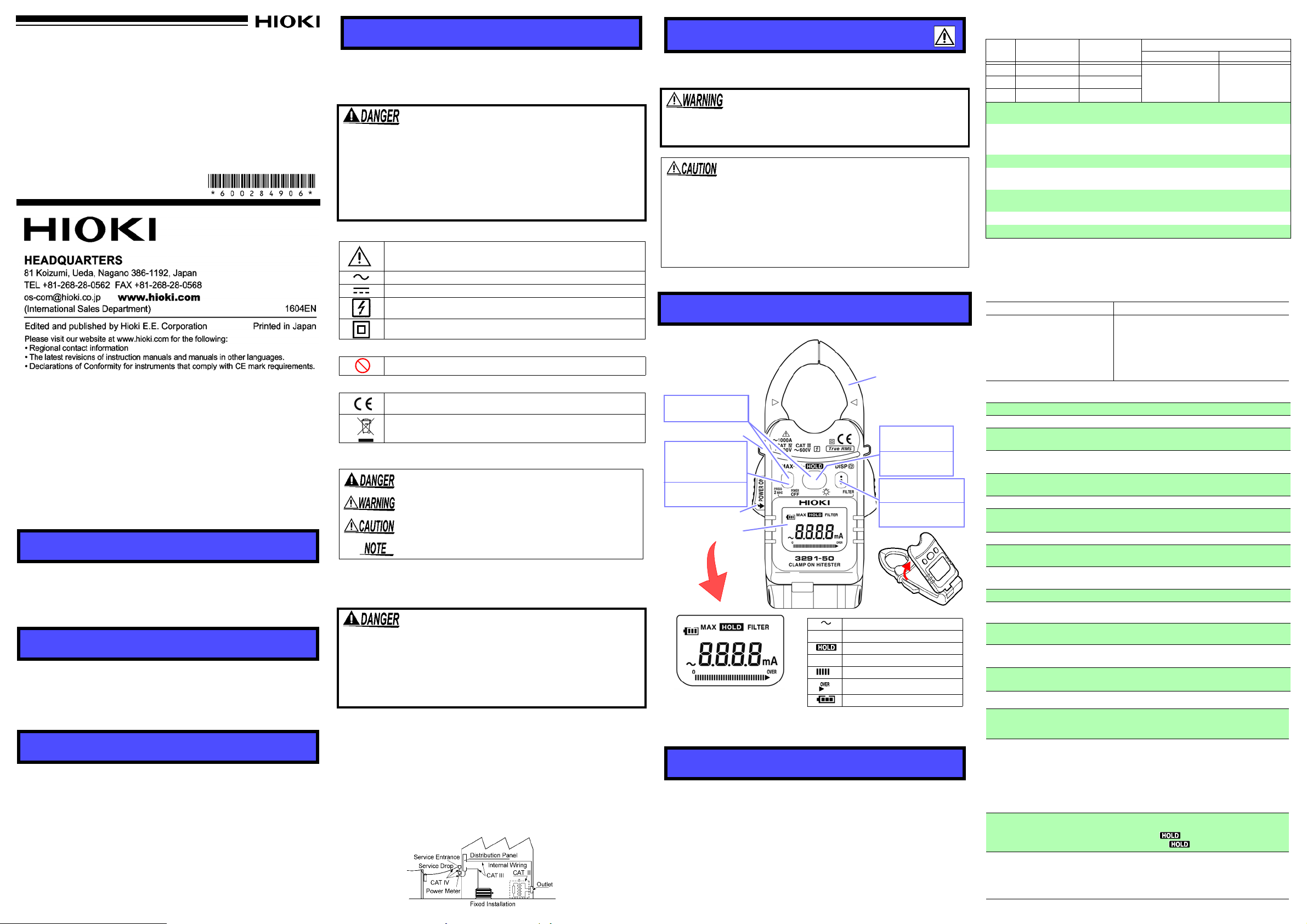
1. Clamp the tester on the conductor, so that the conductor
passes through the center of the clamp core.
• Clamp the tester on one wire only.
• Put the conductor perpendicular to the sensor , as show n in the sketch.
2. The effe ctive value is shown on the digital display.
OK
Display example
3291-50
Previous models
Replacing the Batteries
1.
Press and hold the POWER OFF key for 2 seconds or
longer to turn off the device's power.
2.
Remove the battery cover screws on the back of the device
with a Phillips screwdriver , then remove the battery cover.
3. Replace with a new battery . When inserting a new battery
(CR2032 lithium battery), be sure to position the polarities
in their proper orientations.
4. Replace the battery cover and fasten the screws.
Battery cover
Tighten
Loosen
Position the battery
side is on top.
so that the plus (+)
CALIFORNIA, USA ONLY
This instrument contains a CR Coin Lithium Battery which
contains Perchlorate Material - special handling may apply.
See www.dtsc.ca.gov/hazardou swaste/perchlorate
key
Take measurements with the display
panel flipped open in order to view the
measurement results more clearly, especially in tight locations, without needing
to twist the jaw at an awkward angle.
Display Panel
The display can also be
the key.
reversed by pressing
Make the strap go through the
hole just like the Figure shown.
Auto power-off
Battery Level
Indicator
Back light
Liquid crystal display
(LCD) reversal
Bar graph
Over-Range Display
displayed continuously for 1 minute.
Any key operation is not performed for approx.10
minutes.
To de-activate: Power ON while pressing the key.
Details of operation:Displays 4 levels of remaining
battery charge.
*Refer to “Replacing Battery”.
Activate/De-activate
longer. (About 15 seconds lighting.)
Frequent use of backlight reduces battery life.
Details of operation: Automatically reverses when the
display panel is opened and closed.
Manual reversal: Pressing the key once.
*Refer to “Opening and Closinng the Display Panel”.
Shows the proportion of the measured value to the
range.
Displays “OVER” when a high crest factor current is
inputted, which means an out of the accuracy
guarantee.
*Refer to “Crest factor”.
: Press key for 2 s
econds or
Measurement Procedures
Pre-Operation Inspection (Check the following before using the instrument.)
• Before using the instrument the first time, verify that it operates normally to ensure tha t the no damage oc curred during
storage or shipping. If you find any damage, contact your
dealer or Hioki representative.
• The jaws or the case shall be free of damage. (If damage has
occurred, avoid using the instrument. Use of the instrument
under these conditions may result in electric shock.)
• The mating portions of the jaws should be free of any
scratches or cracks.
• Battery power should be near full capacity when power is
turned on. (Refer to “Replacing Battery”)
• The reading should be around 0 A when no measurements
are being made.
AC Current Measurement
To avoid short circuits and potentially life-threatening hazards, never attach the instrument in current
measurement mode to a circuit that operates at
more than the maximum rated voltage CAT III 600 V,
CAT IV 300 V, or over bare conductors.
• Correct measurement may be impossible for the case of rush
current or significantly fluctuating current.
• There are cases when error could be larger depending on
positioning of sensors and conductor.
• When the measuring value exceeds 1000 A the digital disp lay
will blink.
• Waveforms around 20 Hz or below m ay be displayed as “- -- -”.
• At a low temperature, there are cases whe n the reading may
not be around 0 A without any input signal. But it does not
affect measurement.
Open Jaws to Power On.
Regarding the MAX value display
(1) Press the MAX key once to confirm the MAX value. Whenever a maximum
value is updated, the display will be updated.
(2) A maximum value will be cleared by pressing 【MAX】 key and 【HOLD】key
simultaneously whether when a maximum value is displayed or an instantaneous value is displayed.
• As far as the Data Hold mode is on, MAX value cannot be updated.
• The MAX value is cleared with FILTER ON/OFF.
Filter function
The default setting of Filter is OFF. Please change the setting
according to the use.
Replacing Battery
• To avoid electric shock when replacing the battery first
disconnect the clamp from the object to be measured.
After replacing the batteries, replace the cover and
screws before using the instrument.
• Use only CR2032 lithium battery. Use of any other battery may result in explosion.
• Be sure to insert them with the correct polarity. Otherwise, poor performance or damage from battery leakage
could result.
• Battery may explode if mistreated. Do not short-circuit,
recharge, disassemble or dispose of in fire.
• Handle and dispose of batteries in accordance with local
regulations.
• Keep batteries away from children to prevent accidental
swallowing.
• To avoid corrosion from battery leakage, remove the batteries from the instrument if it is to be stored for a long
time.
Opening and Closing the
Display Panel
Adjust the angle of the display panel for better viewing.
• This instrument should only be connected to the secondary side of a breaker, so the breaker can prevent
an accident if a short circuit occurs. Connections
should never be made to the primary side of a breaker,
because unrestricted current flow could cause a serious accident if a short circuit occurs.
• To avoid electric shock, do not touch the portion
beyond the protective barrier during use.
• Be careful to avoid dropping the instrument or otherwise
subjecting them to mechanical shock, the jaws tip will be
damaged, negatively influencing measurement.
• Do not input current greater than 1000 A. It will damage the
device.
• Please note that waveforms that include elements outside the
frequency characteristic range may not be measured co rrectly.
• Correct measurement may be impossible in the presence of
strong magnetic fields, such as near transformers and highcurrent conductors, or in the presence of strong electromagnetic fields such as near radio transmitters.
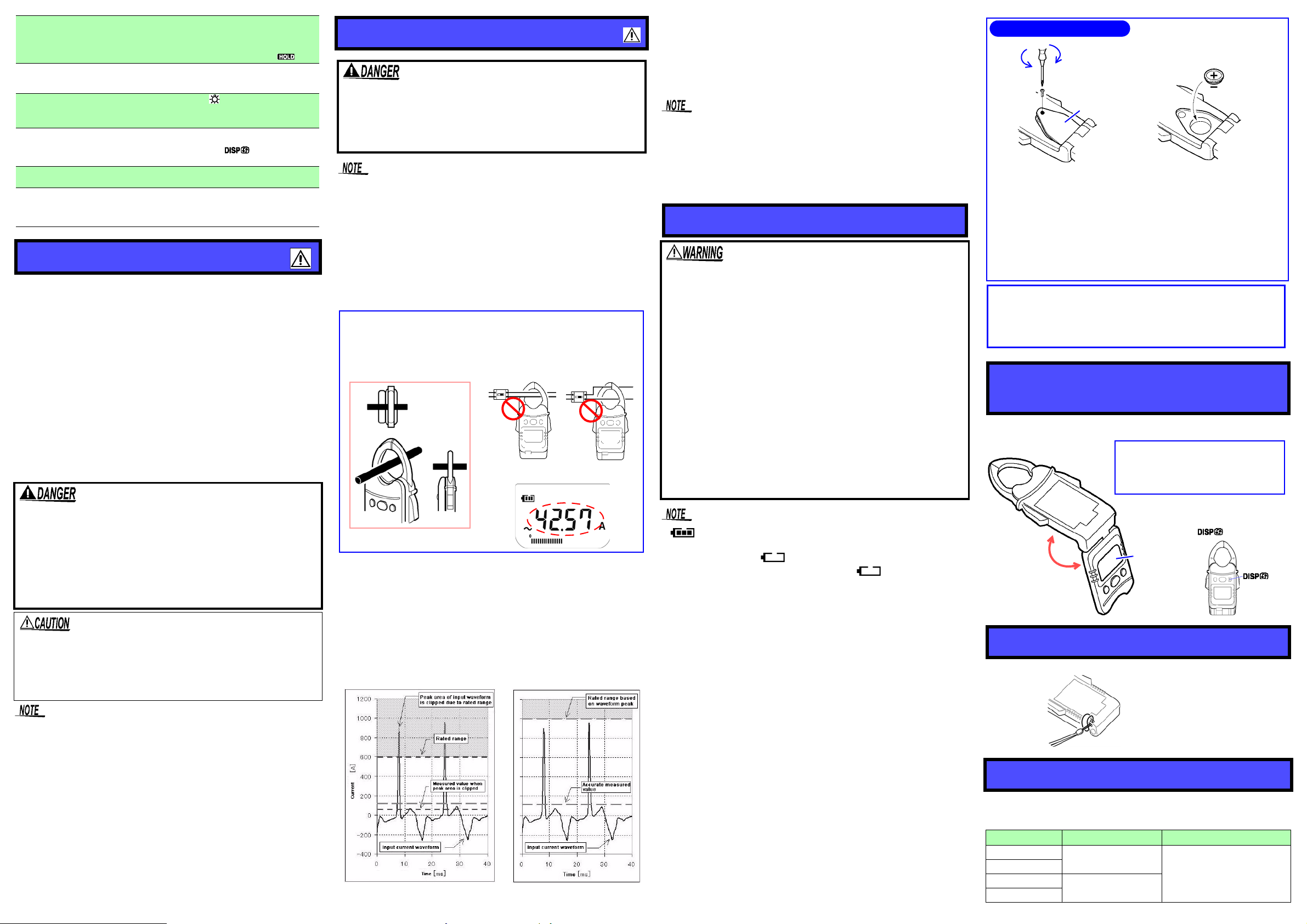
Crest factor
“Crest factor = Waveform peak value/ Internal rated range” is defined for this
instrument. There are cases when the accurate measurement cannot be performed with our previous models, because a top portion of the waveform is
clipped off due to the rated range if a high crest factor current (= RMS is low and
a waveform peak is high) is flowed. This instrument defines the range based on
a waveform peak value and measured value so that the accurate measurement
can be performed. As for a high crest factor current, its measured value becomes small to the range. If a current exceeding a crest factor of 2.8 is inputted,
“OVER” is displayed. This measurement is the out of accuracy guarantee
range and the measured value is for reference purpose only.
• at the upper left on the display screen indicates the
remaining power level. When the battery approaches the
exhausting value, is displayed and a few minutes later,
power turns off automatically. When is displayed, the
accuracy of measurement value is not guaranteed. Replace
the new batteries soon.
• At a low or high temperature, the battery life is reduced faster.
• The batteries included with the device were installed for factory testing purposes. CR2032 lithium batteries can be purchased at electronics and appliance stores where specialized
batteries are sold.
• Although the remaining power level indicator may become
lower for a moment due to the internal proc essing, it is no t an
anomaly.
Attaching the strap
Fix the strap for fall prevention.
Error Display
When an error is displayed on the LCD, the HiTester requires
repair. Contact your supplier or Hioki representative.
Error Display
Err0
Err1
Err2
Err3
Meaning Remedial Action
Internal ROM Error
Calibration Data Faulty
Repair is necessary.
Contact your supplier or Hioki
representative.
 Loading...