

Page 1

INSTRUCTION MANUAL
3290-10
CLAMP ON AC/DC HiTESTER
Page 2

Page 3

10
APPX
Contents
i
Contents
Introduction .................................................................. 1
Checking the Contents of the Package ........................1
Safety Notes ................................................................2
Usage Notes ................................................................5
1Overview 9
1.1 Product Overview ...............................................9
1.2 Features ........................................................... 10
1.3 Identification of Controls and Indicators ...........12
1.3.1 Model 3290-10 CLAMP ON AC/DC Hi T ESTER 12
1.3.2 Model 9691, 9692, 9693 CLAMP ON AC/DC
SENSOR (Optional)............................................18
1.4 Buttons Operations ...........................................19
1.5 Measurement Modes ........................................ 20
1.6 Quick References .............................................21
2 Measurement Preparations 27
2.1 Attaching the Strap ...........................................28
2.2 Connecting Power ............................................29
2.2.1 Installing/ Changing the Batteries ......................29
2.2.2 Connecting the AC Adapter (Optional) ..............30
2.2.3 Using External Power ........................................31
2.3 Connecting the CLAMP ON AC/DC SENSOR .33
2.4 Connecting the Output Cords (Optional) .......... 34
2.5 Turning Power On and Off ...............................35
1
2
3
4
5
6
7
8
9
11
IDX
Page 4

ii
Contents
3 Basic Measurement Procedure 37
3.1 Measuring DC Current .....................................39
3.2 Measuring AC Current ...................................... 40
3.3 DC Integration ..................................................41
3.4 AC Integration by Timer ...................................42
3.5 Outputting Integral Values ................................44
3.6 Measuring Duty by Timer .................................46
4 Measurement Procedure 49
4.1 Verifications Before Measuring ........................ 49
4.2 Selecting the Measurement Parameter ............ 50
4.3 Measuring Current ............................................51
4.4 Measuring Peak Current ..................................62
4.5 Current Integration ...........................................66
4.6 Measuring Duty ................................................79
5 Applicable Measurement Modes 89
5.1 Auto Zero Adjustment Function ........................89
5.2 Display Update Rate ........................................90
5.3 Measurement Response Time ......................... 92
5.4 Filter Function ................................................... 95
5.5 Data Hold .........................................................96
5.6 Viewing Historical Data ....................................97
5.7 Saving Data ....................................................100
5.8 Saving Settings ..............................................101
5.9 Recalling Stored Data ....................................102
5.10 Button Lock .................................................... 102
5.11 Auto Power-off Enabled ................................. 103
5.12 Battery Checking ............................................104
5.13 Battery-Low Warning .....................................105
5.14 Beeper ............................................................106
Page 5

10
APPX
6 Specifications 107
6.1 Measurement Specifications .......................... 107
6.1.1 Current Measurement ......................................108
6.1.2 Frequency Measurement .................................110
6.1.3 Current Integral Measurement .........................111
6.1.4 Duty Measurement ..........................................112
6.2 General Specifications ................................... 113
6.3 CLAMP ON AC/DC SENSOR Specifications . 116
6.3.1 Model 9691 CLAMP ON AC/DC SENSOR ......116
6.3.2 Model 9692 CLAMP ON AC/DC SENSOR ......118
6.3.3 Model 9693 CLAMP ON AC/DC SENSOR ......120
6.4 Combined Accuracy .......................................122
6.4.1 Models 9691 + 3290-10 C om bined Accuracy .1 22
6.4.2 Model 9692 + 3290-10 Combined Accuracy ...124
6.4.3 Model 9693 + 3290-10 Combined Accuracy ...125
6.4.4 Method of Calculation .................. ....................126
7 Maintenance and Service 127
iii
Contents
1
2
3
4
5
6
7.1 Cleaning ......................................................... 127
7.2 Repair and Servicing ......................................128
Appendix 135
Extension Cables .....................................................135
Carrying Case ..........................................................137
Differences between Models 3290 and 3290-10 ..... 139
7
8
9
11
IDX
Page 6

iv
Contents
Page 7
10
Introduction
1
Introduction
Thank you for purchasing the HIOKI “Model 3290-10 CLAMP ON
AC/DC HiTESTER.” To obtain maximum performance from the
meter, please read this manual first, and keep it handy for future
reference.
This manual describes the operation of the 3290-10 when used
with the 9691, 9692, or 9693 CLAMP ON AC/DC SENSOR.
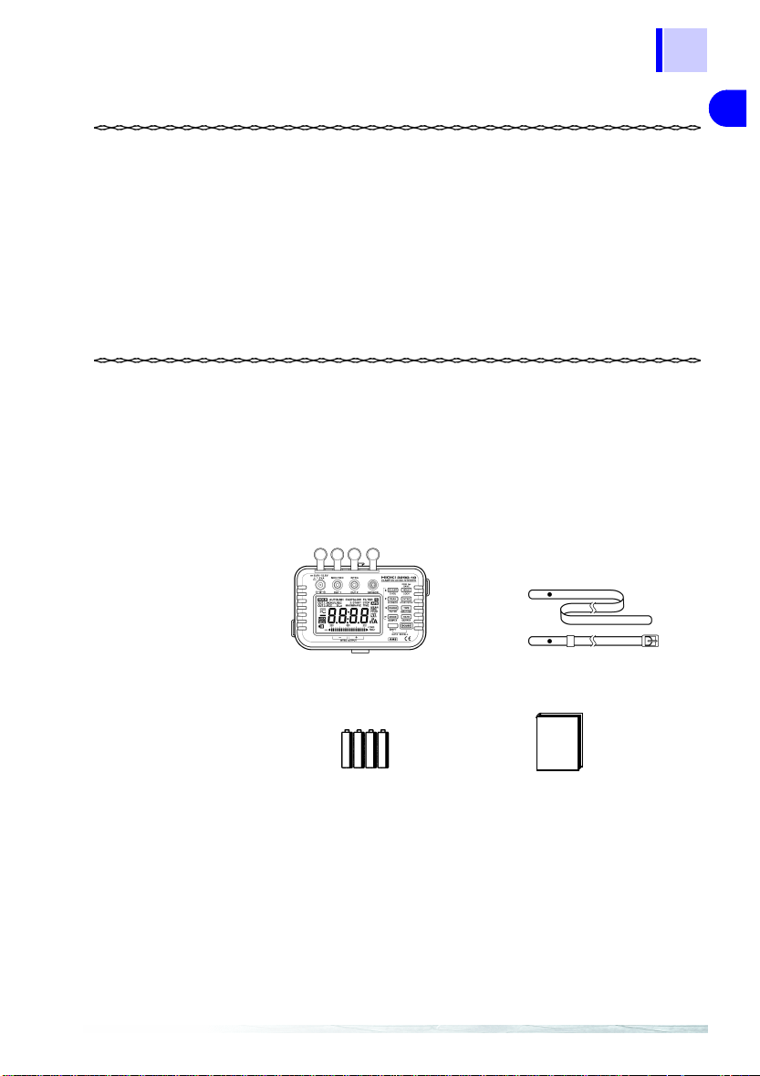
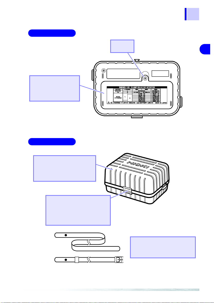
Checking the Contents of the Package
When you receive the meter, inspect it carefully to ensure that no
damage occurred during shipping. In particular, check the accessories, panel buttons, and jacks. If damage is evident, or if it fails to
operate according to the specifications, contact your dealer or
Hioki representative.
Use the original packing materials when transporting the meter, if
possible.
Model 3290-10 CLAMP ON AC/DC HiTESTER
X 1
Strap X 1
1
2
3
4
5
6
7
8
Options
Batteries (LR6) X 4
• Model 9445-02 AC ADAPTER ( SA10-0910N, SINO-AMERICAN)
• Model 9445-03 AC ADAPTER
(SA10-0910G, SINO-AMERICAN, for Europe)
• Model 9094 OUTPUT CORD
• Model 9400 CARRYING CASE
• Model 9691 CLAMP ON AC/DC SENSOR
• Model 9692 CLAMP ON AC/DC SENSOR
• Model 9693 CLAMP ON AC/DC SENSOR
Instruction Manual X 1
9
11
Page 8
2
Safety Note s
Safety Notes
This meter is designed to comply with IEC 61010 Safety Standards, and has been thoroughly tested for safety prior to
shipment. However, mishandling during use could result in
injury or death, as well as damage to th e meter. Be certain
that you understand the instructions and precautions in the
manual before use. We disclaim any respon sibility for acci
dents or injuries not resulting directly from meter defects.
Safety Symbols
This manual contains information and warnings essential for safe
operation of the meter and for maintaining it in safe operating condition. Before using it, be sure to carefully read the following safety
precautions.
-
In the manual, the symbol indicates particularly
important information that the user should read before
using the meter.
The symbol printed on the meter indicates that the
user should refer to a corresponding topic in the manual
(marked with the symbol) before using the relevant
function.
Indicates DC (Direct Current).
Indicates AC (Alternating Current).
Indicates a double-insulated device.
Indicates that the instrument may be connected to or disconnected from a live circuit.
Page 9
Safety No tes
10
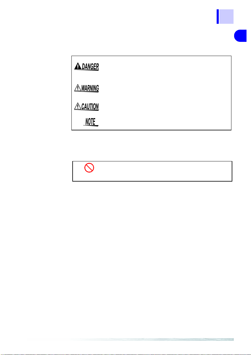
The following symbols in this manual indicate the relative importance of cautions and warnings.
3
Other Symbols
Accuracy
We define measurement tolerances in terms of f.s. (full scale), rdg.
(reading) and dgt. (digit) values, with the following meanings:
f.s. (maximum display value or scale length)
The maximum displayable value or scale length. This is usually the
name of the currently selected range.
Indicates that incorrect operation presents an
extreme hazard that could result in serious injury or
death to the user.
Indicates that incorrect operation presents a significant hazard that could result in serious injury or
death to the user.
Indicates that incorrect operation presents a possibility of injury to the user or damage to the meter.
Indicates advisory items related to performance or
correct operation of the meter.
Indicates the prohibited action.
❖
Indicates the reference.
1
2
3
4
5
6
7
8
9
rdg. (reading or displayed value)
The value currently being measured and indicated on the measuring meter.
dgt. (resolution)
The smallest displayable unit on a digital measuring meter, i.e., the
input value that causes the digital display to show a "1" as the
least-significant digit.
11
Page 10
4
Safety Note s
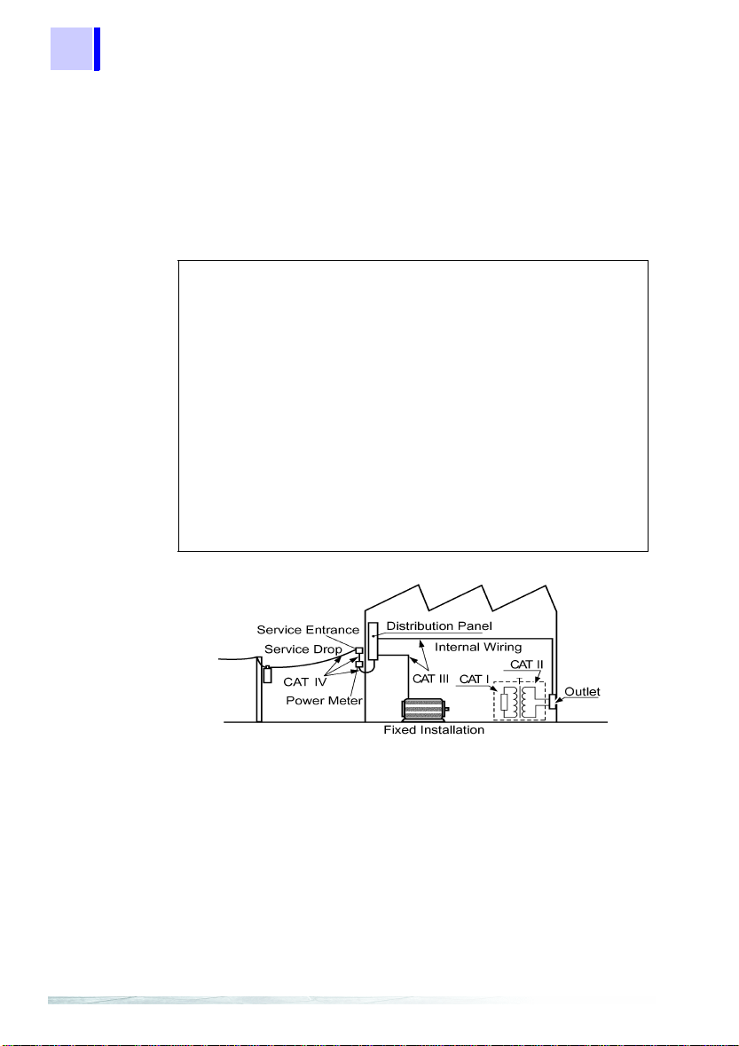
Measurement categories (Overvoltage categories)
This device complies with CATIII (600 V), CATII (1000 V) safety
requirements.
To ensure safe operation of measurement devices, IEC 61010
establishes safety standards for various electrical environments,
categorized as CAT I to CAT IV, and called measurement catego
ries. These are defined as follows.
-
CAT I Secondary electrical circuits connected to an AC
CAT II Primary electrical circuits in equipment connected to
CAT III Primary electrical circuits of heavy equipment (fixed
CAT IV The circuit from the service drop to the service
Higher-numbered categories correspond to electrical environments
with greater momentary energy. So a measurement device
designed for CAT III environments can endure greater momentary
energy than a device designed for CAT II.
Using a measurement device in an environment designated with a
higher-numbered category than that for w hich the device is rated
could result in a severe accident, and must be carefully avoided.
Never use a CAT I measuring device in CAT II, III, or IV environments.
The measurement categories comply with the Overvoltage Categories of the IEC60664 Standards.
electrical outlet through a transformer or similar
device.
an AC electrical outlet by a power cord (portable
tools, household appliances, etc.)
installations) connected directly to the distribution
panel, and feeders from the distribution panel to out
lets.
entrance, and to the power meter and primary over
current protection device (distribution panel).
-
-
Page 11
10
Usage Notes
5
Usage Notes
Avoid the following:
Corrosive or
explosive gases
High temperature
High humidity
Direct
sunlight
Electomagnetic
radiation
Dust
Impact, dropping
Follow these precautions to ensure safe operation and to obtain
the full benefits of the various functions.
Setting Up the 3290-10
• This meter should be installed and operated indoors only,
between 0 and 40°C and 80% RH or less.
• Do not use the meter where it may b e exposed to corrosive or
combustible gases. The meter may be damaged.
• Do not store or use the meter where it could be exposed to
direct sunlight, high temperature or humidity, or condensation.
Under such conditions, the meter may be damaged and insula
tion may deteriorate so that it no longer meets specifications.
• This meter is not designed to be entirely water- or dust-proof. Do
not use it in an especially dusty environment, nor where it might
be splashed with liquid. This may cause damage.
• Do not use the meter near a source of strong electromagnetic
radiation, or near a highly electrically charged object. These may
cause a malfunction.
• To avoid damage to the meter, protect it from physical shock
when transporting and handling. Be especially careful to avoid
physical shock from dropping.
1
2
3
4
5
-
6
7
8
9
Correct measurement may be impossible in the presence of
strong magnetic fields, such as near transformers and high-cur
rent conductors, or in the presence of strong electromagnetic
fields such as near radio transmitters.
-
11
Page 12
6
.
Usage Notes
Preliminary Checks
Before using the meter the first time, verify that it operates normally
to ensure that the no damage occurred during storage or shipping.
If you find any damage, contact your dealer or Hioki representative.
Before using the meter, make sure that the insulation on the
probes is undamaged and that no bare conductors are
improperly exposed. Using the meter in such conditions
could cause an electric shock, so contact your dealer or
Hioki representative for repair.
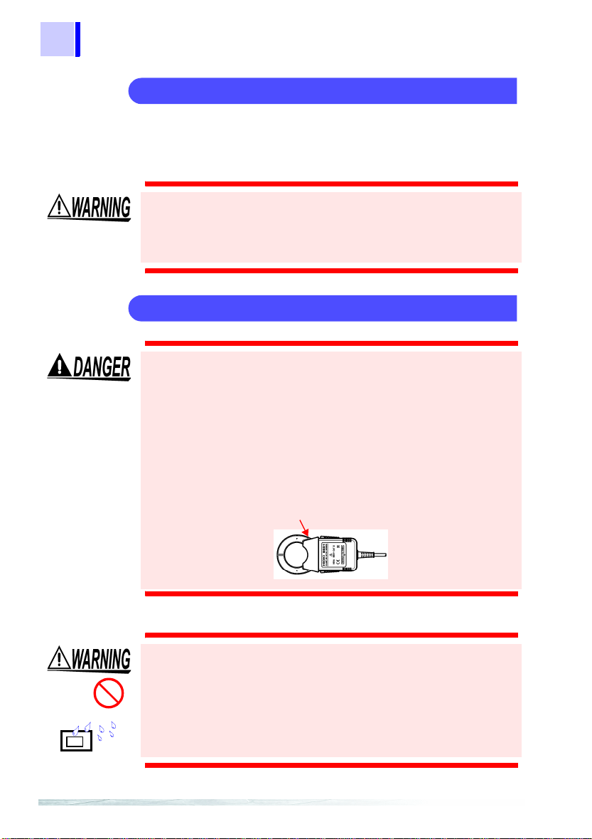
Measurement
• To avoid short circuits and potentially life-t hreatening hazards, never attach the clamp to a circuit that operates at
more than 600V, or over bare conductors.
• Clamp sensor should o nly be connected to the secondary
side of a breaker, so the breaker can preven t an a ccident if
a short circuit occurs. Connections should nev er be made
to the primary side of a breaker, because unrestricted cur
rent flow could cause a serious accide nt if a short circuit
occurs.
• To avoid electric shock, do not touch the portion be yond
the protective barrier during use.
Barrier
-
Do not get wet.
This model is the 9661
• Do not allow the meter to get wet, and do not take measurements with wet hands. This may cause an electric shock.
• To avoid electric shock when measuring live lines, wear
appropriate protective gear, such as insulated rubber
gloves, boots and a safety helmet.
Page 13
7
10
Usage Notes
• The maximum continuous-input limit is obtained from the temperature increase due to self-heating during measurement. To
prevent damage to the clamp-on sensor, do not input a current
exceeding this limit.
• The maximum continuous-input limit varies depending on the
clamp-on sensor and the frequency of the current to be mea
sured.
❖ Maximum continuous-input limit varies:
See Section 6.3 "CLAMP ON AC/DC SENSOR Specifications" (page 116)
Each sensor’s derating acording to frequency
•The indicator appears when battery voltage becomes low.
Replace the batteries as soon as possible.
• After use, always turn OFF the power.
• Attach the clamp around only one conductor. Single-phase (2wire) or three-phase (3-wire) cables clamped to gether will not
produce any reading.
1
-
2
3
4
5
OK
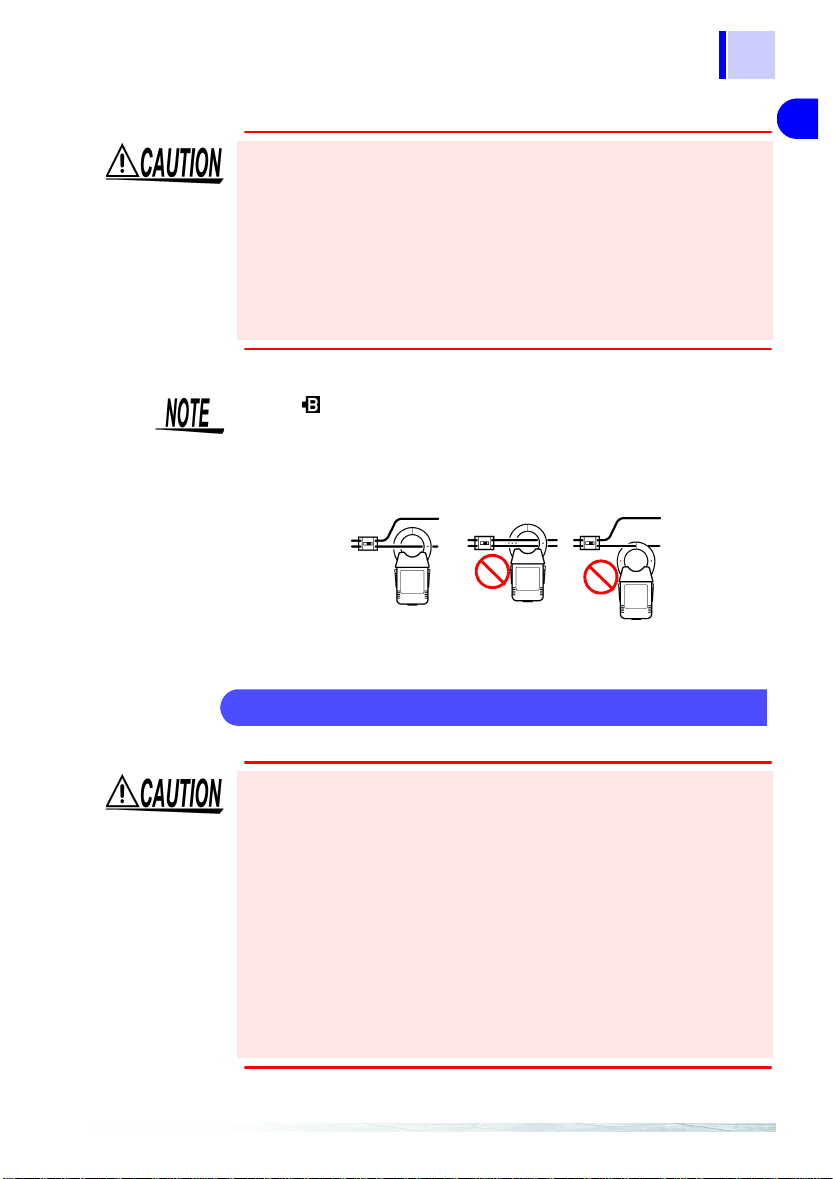
Handling the Clamp Sensors
• The ends of the clamp sensor are very delicate. Be careful not to
drop the sensor or subject it to impact. If the sensor is deformed
or the contact surfaces of the clamps are damaged, the mea
surement may not be accurate.
• Be careful to avoid dropping the clamps or otherwise subjecting
them to mechanical shock, which could damage th e mating surfaces of the core and adversely affect measurement.
• The top part of the clamp sensor above the barrier (including the
clamps, but not the lever) is provided with double insulation to
ensure safety. Be careful not to drop the sensor or otherwise
subject it to impact. A damaged sensor may result in electric
shock during measurement. In case of sensor damage, contact
us immediately for repair or discard the damaged sensor to
avoid subsequent use.
-
6
7
8
9
11
Page 14

8
Usage Notes
Page 15

1.1 Product Overview
10
Overview 1
1.1 Product Overview
The 3290-10 CLAMP ON AC/DC HiTESTER is used with the 9691,
9692, or 9693 CLAMP ON AC/DC SE NSOR. These sensors are
interchangeable and any model can be used with the 3290-10.
The 3290-10 automatically detects the sensor connected and sets
up the appropriate range. When combined with the 9 691, 9692, or
9693 Sensor, the 3290-10 HiTESTER can perform DC, AC, and
AC+DC measurement of a live pow er line. In addition, current inte
gral and duty measurement functions are provided.
As well as operating from batteries or AC adapte r, operation from
an external DC power source is supported for long-term measure
ments.
See page 139 for details of the differences with the Model 3290
CLAMP ON AC/D C HiTESTER.
9
1
Overview
2
3
4
-
-
5
6
7
8
9
11
Page 16
10
1.2 Features
1.2 Features
Current integration functions
(total, positive and negative integrals)
Polarity-specific positive and negative current integrals can be
measured (at ten samples/second)
D/A output (selectable total, positive or negative integral).
Measures the mean current value within a specified interval (total
integral / integration interval).
Operating time and duty measurement
Any value can be set as the operating state threshold.
Duty (%) = operating time / measurement time X 100
Timer measurements available
(integral and duty measurements)
Measurement times can be set from one minute to 99 hours, 59
minutes.
Repeating measurements
Any timer can be set to perform up to 20 repeated measu rements.
Historical measurement data confirmation
Data from repeating measurements can be stored (integrals, interval mean, peak, maximum, minimum, duty and operating time).
Data storage
Measurement data and settings can be stored by pressing the
button for two seconds, and upon auto power-off or forced
power off due to low battery voltage.
Data recall
Holding the SHIFT button while pressing the button to turn the
meter on recalls stored data.
Peak measurement
Positive and negative current waveform peak values can be displayed in DC mode.
Page 17

11
10
1.2 Features
Low-frequency current measurement
AC current as low as 1 Hz can be measured in the SLOW AC+DC
mode.
1
Overview
Filter function
Switchable 500-Hz low-pass filter (in AC and AC+DC modes)
Switchable 1-Hz low-pass filter (in DC mode, for MON output)
AC+DC measurement
Measures superimposed AC and DC components and full- and
half-wave rectified waveforms.
Selectable measurement response time
Measurement response time can be set to FAST, NORMAL or
SLOW (in AC and AC+DC modes).
Multiple power source support
Accepts power from batteries, optional AC adapter or external DC
source.
Extension cable options
An extension cable can be connected between the meter and the 9691,
9692 or 9693 CLAMP ON AC/DC SENSOR. Optional extension cables
are available with lengths of 5, 10, 20, 30, 50 or 100 m.
2
3
4
5
6
7
8
9
11
Page 18
12
s
1.3 Identification of Controls and Indicators
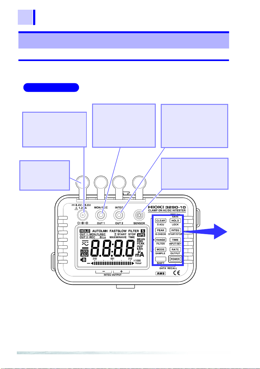
1.3 Identification of Controls and Indicators
1.3.1 Model 3290-10 CLAMP ON AC/DC HiTESTER
Front Panel
AC Adapter
Connection Jack
The optional AC adapter
can be connected here to
power the meter.
Dust Caps
Used to protect the
jacks in a dusty environment.
Output Jack 1 (OUT1)
Connect the optional
9094 OUTPUT CORD to
this jack to obtain output
during current measurement.
Output Jack 2 (OUT2)
Connect the optional 9094
OUTPUT CORD to this
jack to obtain output during
integral measurement.
Sensor Jack (SENSOR)
Connect the 9691, 9692, or
9693 CLAMP ON AC/DC
SENSOR to this jack.
Buttons
Operation
Page 19
1.3 Identification of Controls and Indicat or s
10
Notation for multi-button operations
A B
+ : Press Button A and button B at the same time.
Example: SHIFT +
Press the
A B
→ : Press Button A and then press Button B.
Example: SHIFT →
After pressing the
play), press the
SHIFT and POWER buttons at the same time.
SHIFT button ( appears on the dis-
POWER button.
13
1
Overview
2
3
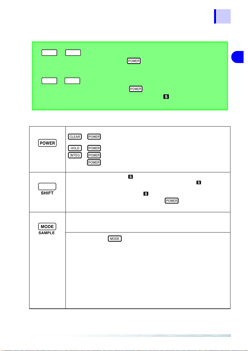
Buttons Operations
Turns power ON/OFF.
SHIFT + : Stored data such as integral values can be reviewed.
• Pressing this button causes to display, indicatin g tha t the a ddi ti on al function
(in blue letters) allocated to each button is available. To turn off, press the
SHIFT button again.
• Some buttons may be locked when is on.
• Holding the SHIFT button while pressing the button to turn the meter
on enables review of stored data such as integral values.
• Selects the current and frequency measurement mode.
DC → AC → AC+DC → Hz
• Button presses are ignored while TIME is displayed.
SAMPL (SHIFT → ):
• Switches display of refresh rate and measurement response time.
(AC and AC+DC modes) (see pages 90 and 92)
NORMAL (twice/ sec) → SLOW (once/ 3 sec) → FAST (10 times/ sec)
DC mode is fixed at once per second.
• The display update rate is usually set to NORMAL.
(Note that there is no indication for
• SLOW decelerates the speed of updating on-display measurement.
(with SLOW on)
Measurement response time also becomes SLOW.
• FAST accelerates the speed of updating on-display measurement.
(with
Measurement response time also becomes FAST.
+ : Cancels saved se tting s (retur ned t o fact ory defau lts) and erase s
stored measurement data. (see pages 100 and 101)
+ : Disables the auto power-off function. (see page 104)
+ : Turns off the beeper. (see page 107)
(see page 103)
(see page 103)
(see page 52)
NORMAL.)
FAST on)
4
5
6
7
8
9
11
Page 20
14
1.3 Identification of Controls and Indicators
Current Measurement (see page 53)
• Selects auto range or manual range.
(Hz mode uses auto-ranging only) AUTO → L → H
• The current ranges for the 9691 and 9692 are 20 A and 200 A; the ranges for
the 9693 are 200 A and 2000 A.
• Button presses are ignored while TIME is displayed.
Integral Measurement (see page 70)
• Selects auto range or manual range.
• Available ranges depend on the connected clamp-on sensor.
• Five ranges can be manually selected for each integral range (four ranges are
shared in common as H and L ranges).
(SHIFT → ): (see page 95)
FILTER
•DC Mode
Applies low-pass filtering at about one Hz to the output when output jack 1
(OUT1) is set to MON output (low-pass filtering at about 0.5 Hz is always
applied to the display).
• AC and AC+DC Modes
Applies low-pass filtering at about 550 Hz to the display and output.
•DC Mode (see page 63)
Displays positive and negative peak values.
Peak measurement dete rmines the pe ak (cr est va lue) of th e curre nt wavef orm.
(Peak Hold)
+ PEAK → - PEAK
• AC and AC+DC Modes
Displays peak (absolute), maximum and minimum values (current measurement).
PEAK → MAX → MIN
(see page 63)
B.CHECK
• Displays remaining battery charge.
• When TIME and STOP are displayed, clears INTEG (integrals), RATE (duty)
• Clears data to “0” during peak measurement.
• Holding down the button and turning power on initializes the setting
0 ADJ (SHIFT → ): (See page 89)
• Performs auto zero adjustment in DC and AC+DC modes.
(SHIFT → ): (See page 105)
When the remainin g ba tte ry charge indicates 0%, the indicator (low-battery
warning) appears.
and PEAK data values on the corresponding displays (see pages 69 and 80).
(see page 65)
save function and restores the default settings. (See page 101)
Page 21
15
10
1.3 Identification of Controls and Indicat or s
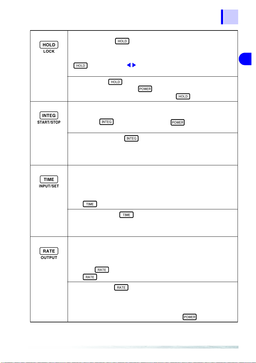
• Suspends or deactivates the display-updatin g functi on .
• Holding down the button and turning power on disables the auto
power-off fu nction.
• Press and hold for two seconds to store settings and data. (See page 101)
• When TIME is displayed (other than when current is displayed), after pressing
button, press the buttons to review INTEG, RATE or PEAK mea-
surement history.
LOCK (SHIFT → ): (see page 103)
• Locks all buttons including the button.
• To cancel, press SHIFT button again, then press button.
• Displays the integral and interval mean current values (see page 74)
DC Mode: total integral → positive integral → negative interval → interval mean va lue
AC and AC+DC Modes: integral → interval mean value
• Holding the button while pressing the button to turn the meter
on disables the beeper.
START/STOP (SHIFT → ): (see pages 74 and 85)
• Starts and stops current integral and duty measurement.
When STOP is displa yed, measurement starts (and START appears)
When START is displayed, measurement stops (and STOP appears)
• TIME is displayed.
• Displays elapsed time from when measurement was started by the START/STOP
button, the timer setting and repetition number (alternating once per second).
Elapsed tim e → timer setting and repetition number
Elapsed time is displayed normally up to 99 hours and 59 minutes.
If the total time of repeating timer measurements exceeds 100 hours, the time
unit indicator (h) is di splayed.
• The button has to be pressed in order to set the timer.
(see page 104)
(see page 97)
(see page 107)
1
Overview
2
3
4
5
6
7
INPUT/SET
• Enables the setting display for the timer and current threshold (only for duty
measurement).
• Accepts displayed settings.
• Displays the duty, operating time and current threshold (see page 81)
Duty → operating time → current threshold
• Although no "%" unit indicator appears for duty measurements, the displayed
value is percentage.
• When the duty value exceeds 100 hours , "h" is d ispla yed to indicate hour u nit s.
Press the button to display.
• The button has to be pressed in order to set the current threshold.
OUTPUT
• Makes output settings (for current and integral measurements).
• Settings for the two output jacks are limited according to measurement mode.
• The auto power-off function i s di sab le d. Ho wev er, when the timer is set, data i s
stored and power turns off about 10.5 minutes after the timed measurement
ends (stored data can be read by pressing SHIFT + buttons).
(SHIFT → ): (see pages 67 and 82)
(SHIFT → ): (see pages 54 and 71)
8
9
11
Page 22

16
1.3 Identification of Controls and Indicators
LCD
OUT1
OUT2
MON
MON.FL
REC
AUTO
L
H
FAST
SLOW
Direct Curren t (DC)
Alternating Current (AC)
Alternating Current and Direct
Current (AC+DC )
Auto zero adjustment is active.
Low battery warning
FILTER
MAX
MIN
AVE
TIME
500 Hz filter is active.
Maximum value
Minimum value
Interval mean current value
Stores integral and
duty measurement data
Setting of OUT1 RMS True root mean square value
Setting of OUT2
Data hold function
PEAK
Hz
Wave peak value
Frequency
Monitor is active. Button lock is active.
1 Hz filter for monitor is active.
Record is active.
Auto power-off is active.
Auto-range
Current L (low) range
A
Ah
START
STOP
hour
Current
Integral value
Starts integral or duty measure-
ment
Stops integral or duty measure-
ment
100 hours/segment (bar graph)
Current H (high) range Input over (bar graph)
Display-updating 10 times/sec. SHIFT
Display updating approx.
once/3 sec.
The letter of LCD is clearest, when it sees from the front side.
Page 23
10
Bottom Panel
17
1.3 Identification of Controls and Indicat or s
Battery Cover
Unfasten the screw,
then remove the case
to replace the battery.
Others
Top Case
Cover the 3290-10 with this
case when not in use to protect
the LCD, buttons and jacks.
Screw
1
Overview
2
3
4
5
6
7
8
Top Case Clasp
Insert the clasp into the top
case to attach the case. Move
the top case to the rear during
measurement.
Strap
Used to hang the 3290-10
around neck so as not to drop it.
9
11
Page 24
18
1.3 Identification of Controls and Indicators
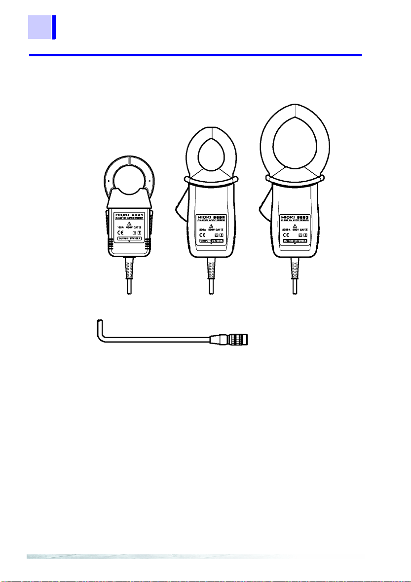
1.3.2 Model 9691, 9692, 9693 CLAMP ON AC/DC SENSOR (Optional)
Model 9691
Model 9692
Output Connector
Model 9693
Page 25
10
1.4 Buttons Operations
19
1.4 Buttons Operations
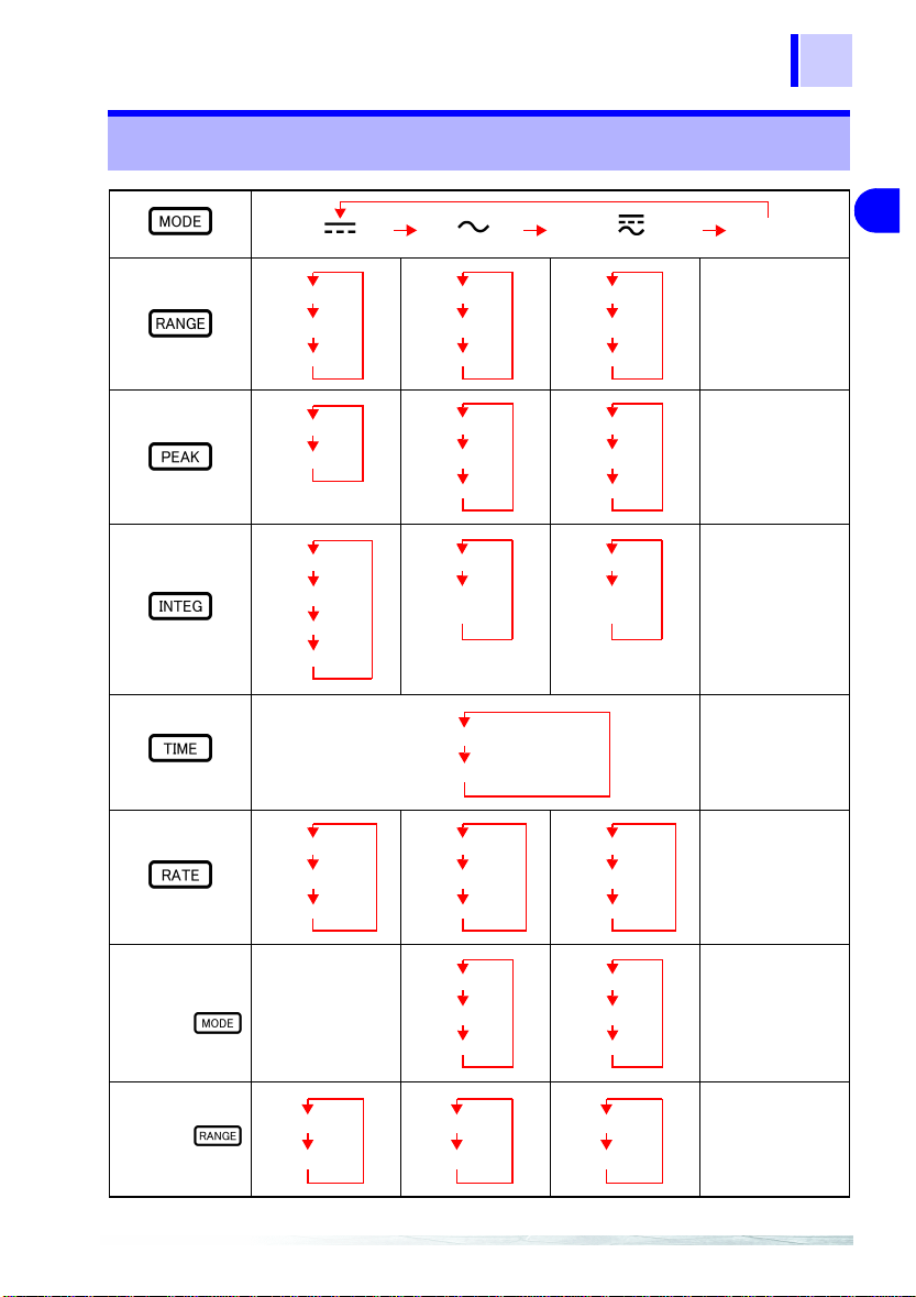
DC
AUTO range
L range
H range
+ PEAK
- PEAK
T otal integral
Positive integral
Negative integral
Elapsed time
Timer setting time (repetition number)
Duty
Operating time
Current threshold
AC AC+DC
AUTO range
L range
H range
PEAK
MAX
MIN
Integral value
Interval mean
current value
Elapsed time
Duty
Operating time
Current threshold
AUTO range
L range
H range
PEAK
MAX
MIN
Integral value
Interval mean
current value
Duty
Operating time
Current threshold
Hz
AUTO range
--
--
--
--
1
Overview
2
3
4
5
6
7
8
9
SAMPLE
SHIFT →
FILTER
SHIFT →
NORMAL
-- --
MON
MON.FL
SLOW
FAST
OFF
ON
NORMAL
SLOW
FAST
OFF
ON
11
--
Page 26
20
1.5 Measurement Modes
1.5 Measurement Modes
For current, three modes are provided: DC (direct current, ), AC
(alternating current, ), and AC+DC (alternating current and
direct current, ) modes. Select a proper mode according to the
waveform shown below:
Mode
DC
()
AC
()
Input
waveform
Display
OUTPUT (only for current mode)
REC MON MON.FL
Yes
0 0 0
0 0 0
No
Not measurable
Setting impos-
sible
Average
0 0 0
measurement
No
Not measurable
0
0
(zero displayed)
Yes
0 V
0
0
No
0
Not measurable
0
No
0
Not measurable
0
0 V
0
0
0
0
Yes
0 0 0
(without polarity)
--
AC+DC
()
AC2DC2+
0
Yes
0
0
--
Yes
0
0
0
Yes
0
0
0
Page 27
10
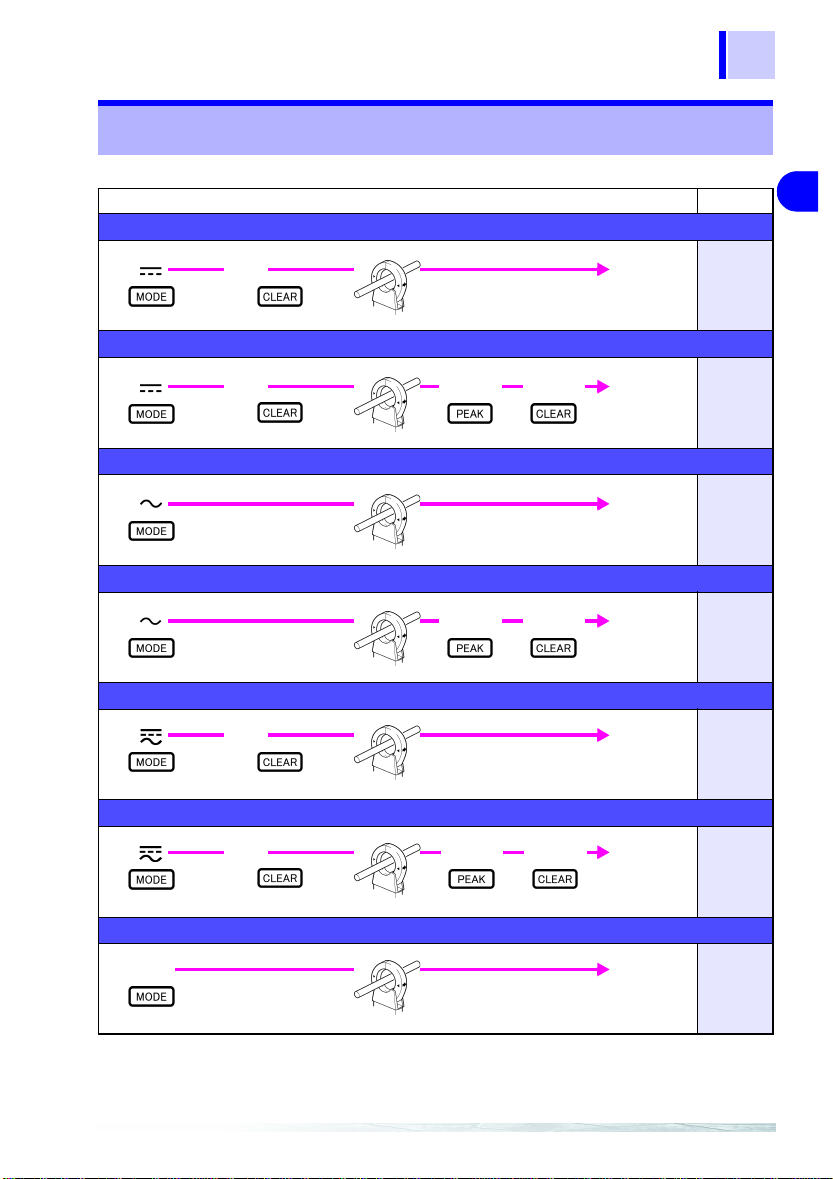
1.6 Quick References
21
1.6 Quick References
DC measure ment
ADJ
→
SHIFT
DC peak measurement
ADJ
→
SHIFT
AC measure ment
AC peak measurement
AC+DC measurement
ADJ
→
SHIFT
Press twice
AC+DC peak measurement
Operations Page
Measure-
PEAK
PEAK
CLEAR
CLEAR
ment
Measurement
Measurement
Measurement
Measurement
51
62
51
62
51
1
Overview
2
3
4
5
6
7
8
9
SHIFT
Hz measurement
Hz
Press three times
ADJ
→
PEAK
CLEAR
Measurement
Measurement
62
11
51
Page 28
22
-
1.6 Quick References
DC integral measurement
Operations Page
INTEG CLEAR
DC interval mean current measurement
INTEG CLEAR
AC integral measurement
INTEG START
CLEAR
AC interval mean current measurement
INTEG
CLEAR
SHIFT
SHIFT
SHIFT
SHIFT
START
→
SHIFT
ADJ
→
START
→
ADJ
→
START
Press three times
SHIFT
→
Measure-
66
ment
AVE
Measurement
66
Measure-
AVE
ment
Measure
→
ment
66
66
AC+DC inte gral measurement
INTEG
Press twice
CLEAR ADJ
→
SHIFT
SHIFT
START
→
66
Measurement
Page 29
10
Operations Page
AC+DC interval mean current measurement
23
1.6 Quick References
INTEG
Press twice
DC duty and operating time measurements
Duty
Display
ADJ
→
SHIFT
AC duty and operating time measurements
Duty
Display
CLEAR ADJ
Numerical
CLEAR
CLEAR
Entry Display
→
SHIFT
Display the duty
SHIFT
Numerical
Entry Display
SHIFT
Display the duty
SHIFT
START
→
START
SHIFT
SHIFT
→
→
→
START
→
AVE
Setting
Display the
operating time
Setting
Display the
operating time
SHIFT
SHIFT
Measurement
Accept the
Setting
→
Measurement
Accept the
Setting
→
Measurement
1
Overview
66
2
3
4
79
5
6
7
79
8
AC+DC duty and operating time measurements
Press twice
SHIFT
ADJ
→
Duty
Display
CLEAR
Numerical
Entry Display
→
SHIFT
Display the duty
START
→
SHIFT
Setting
Display t he
operating time
Accept the
Setting
SHIFT
→
Measurement
9
79
11
Page 30
24
1.6 Quick References
View elapsed measurement time
Set the timer
Operations Page
66, 79
Timer
Display
Numerical
Entry Display
→
SHIFT
Setting
Set the number of repetitions
Timer
Display
Numerical
Entry Display
SHIFT
→
Press four times
Number of Times
Display
View timer and repetition settings
Press twice
View current threshold setting
Press three times
Low-frequency (below 10 Hz) current measurement
Press twice
SHIFT
SLOW
→
SHIFT
ADJ
→
Accept the
SHIFT
Setting
→
SHIFT
Accept the
Setting
→
Measurement
66, 79
66, 79
66, 79
79
51, 92
Measure starting current
FAST
→
SHIFT
Press twice
MAX CLEAR
Press twice
Measurement
51, 90
Page 31

10
Make output settings
25
1.6 Quick References
Operations Page
Output
→
SHIFT
Change the display update rate (AC and AC+DC modes)
→
SHIFT
Obtained through a low-pass filter (LPF) set to 1 Hz (MON Output Filter Function) (DC mode)
→
SHIFT
Obtained through a low-pass filter (LPF) to measurement value and output. (Filter Function)
(AC and AC+DC modes)
→
SHIFT
Store data (while TIME is displayed)
Hold down 2 seconds
OUT1: MON
OUT2: REC
Bar graph
SLOW → FAST → NORMAL
OUT1: MON
OUT2: REC
FILTER is displayed.
DC
→
±)
(
→
Disable:
MON
REC
(+)
MON.FL
REC
MON
→
REC
(-)
Disable:
Disable:
Power ON
+
OUT1: REC
OUT2: REC
SHIFT
SHIFT
AC, AC+DC
MON
→
REC
→
→
51, 62
90, 92
95
95
100
1
Overview
2
3
4
5
6
7
8
Store settings (while TIME is not displayed)
Hold down 2 seconds
Recall stored data (data recall)
Power ON
+
SHIFT
Disable:
Power ON
+
9
101
11
103
Page 32

26
1.6 Quick References
Operations Page
View repetition data (TIME is displayed)
→
→
Verify remaining battery charge
→
SHIFT
Suspend display updating (TIME is not displayed)
HOLD is displayed.
Button lock
SHIFT
→
LOCK is displayed.
Disabling the auto power off function
Power ON
+
APS is not displayed.
Disabling the beep tone
Disable:
Disable:
SHIFT
97
105
96
→
103
104
Power ON
+
107
Page 33

10
Measurement Preparations 2
e
"
27
1
Attaching the Strap
Connecting Power
Connecting the Clamp-on Sensor
Connecting the Output Cords
Turning Power On
❖See Section 2.1 "Attaching the
Strap" (page 28)
❖See Section 2.2 "Connecting
Power" (page 29)
❖See Section 2.3 "Connecting th
CLAMP ON AC/DC SENSOR
(page 33)
❖
See Secti on 2.4 "Conne cting
the Output Cords (Optional) "
(page 34)
❖See Section 2.5 "Turning Power
On and Off" (page 35)
2
Measurement Preparations
3
4
5
6
7
8
9
Page 34

28
2.1 Attaching the Strap
2.1 Attaching the Strap
Using the 3290-10 with the strap attached improves operability.
1. Fasten the two straps together into
one.
2. Attach each e nd to the 3290-10 as
shown in the figure above.
Page 35

2.2 Connecting Power
10
2.2 Connecting Power
2.2.1 Installing/ Changing the Batteries
29
1
• To avoid electric shock when r eplacing the batteries, first
disconnect the clamp from the object to be measured.
• After replacing the batteries, replace the cover and screws
before using the meter.
• Do not mix old and new batteries, or different typ es of batteries. Also, be careful to observe battery polarity during
installation. Otherwise, poor p erformance or damage from
battery leakage could result.
• To avoid the possibility of explosion, do not short circuit,
disassemble or incinerate batteries.
• Handle and dispose of batteries in accordance with local
regulations.
Remove the ba tteries when ope rating from exte rnal power. When
the batteries are installed, the 3290-10 will turn on even if the polar
ity of the external power is reversed, damaging the meter.
•The indicator appears when battery voltage becomes low.
Replace the batteries as soon as possible.
• If AC power is lost due to a power outage, measurement can
continue if the batteries have been installed (available backup
time depends on battery condition).
• While operating from the AC adapter, the remaining battery
charge indicator (bar graph) indicates the loaded output volt
age (about 6V) of the AC adapter. Although this may not display as 100%, measurements are unaffected.
-
2
Measurement Preparations
3
4
5
-
6
7
8
9
1. Confirm that the 3290-10 is turned off.
2. Use a Phillips screwdriver to unfasten the
setscrew on the battery cover.
3. Remove the battery cover.
4. Insert (Change) four new batteries while
confirming the correct polarity.
5. First fit the tab of the cover, then fit the
cover. Secure the cover in place by tighten
ing the setscrew.
-
Page 36

30
2.2 Connecting Power
2.2.2 Connecting the AC Adapter (Optional)
• Turn the meter off before connectin g the AC adapter t o the
meter and to AC power.
• Use only the specified Model 9445-02 AC ADAPTER (SA100910N, SINO-AMERICAN). AC adapter input voltage range
is 100 to 240 VAC (with ±10% stability) at 50/60 Hz. To avoid
electrical hazards and damag e to the meter, do not apply
voltage outside of this range.
• Make sure the power is turned off before connecting or discon-
necting the AC adapter.
• When using the AC adapter, note that current of approximately
3 mA is consumed regardless of whether th e power switch of
the meter is on or off. (Battery power is not consumed, how
ever, when power is turned off.)
• When the power supply is switched over from the battery to the
AC adapter or vice versa during peak measurement, an inac
curate measurement result (i.e., value larger than the actual
value) may be displayed.
• While operating from the AC adapter, the remaining battery
charge indicator (bar graph) indicates the loaded output volt
age (about 6V) of the AC adapter. Although this may not display as 100%, measurements are unaffected.
• The AC adapter may be used either with or without the batteries.
• If the AC adapter is connected but not providing power, mea-
surement is still possible if the batteries have been installed
(available backup time depends on battery condition).
When operating from the AC adapter, voltage is internally regulated to about 6 V. When battery voltage is higher than this
(such as with new batteries), the batteries power the meter
until battery voltage decreases, at which point operation
switches to the AC adapter.
-
-
-
Connecting the AC Adapter
1. Confirm that the 3290-10 is
turned off.
2. Remove the d ust cap over the
AC adapter jack, and plug in
the AC adapter securely.
3. Plug the AC adapter into a
wall outlet.
Page 37

10
2.2.3 Using External Power
• To avoid electric shock and short-circuit accidents when
connecting the optional 2m external po wer cable, first be
sure the meter is turned off.
• The external voltage requirements are 8.4 to 15.6 V DC at
1.2 VA. To avoid malfunctions or damage to the meter and
electric accidents, use only a power source that meets
these requirements.
• To avoid electric shock, connect the negative side to an
earth or chassis ground.
31
2.2 Connecting Power
1
2
Measurement Preparations
3
4
Connecting the External Power Cable
1. Confirm that the meter is t urned
off.
2. Remove the dust cap over the
AC adapter jack, and plug in the
external power cable securely.
3. Connect the external power
cable to the external power
source.
5
6
7
8
9
Page 38

32
2.2 Connecting Power
Observe the following to avoid damaging the meter:
• When using an external power source such as a battery, connect the positive (center) conductor of the external power cable
to the "+" battery terminal.
• Remove the batteries when operating from external power.
When the batteries are installed, the meter will turn on even if
the polarity of the external power is reversed, damaging the
meter.
• If the device under test is earth grounded, connect the negative
conductor to earth.
(Example: Indoor and outdoor line measurements R connect the
negative conductor to earth)
• If the device under test uses a ground level that is isolated from
earth, connect the negative conductor to the ground level used.
(Example: In a mobile installation, if the device under test is
grounded to the vehicle chassis R connect the negative conduc
tor to the chassis)
Plug
Battery
-
• Make sure the power is turned off before connecting or discon-
necting the external power cable.
• When using the external power, note that current of approxi-
mately 3 mA is consumed regardless of whether the power
switch of the 3290-10 is on or off.
• While operating from the external power, the remaining battery
charge indicator (bar graph) indicates the loaded output volt
age (about 6V) of the external power. Although this may not
display as 100%, measurements are unaffected. However,
proper operation cannot be guaranteed if external power drops
below 8.4 V.
• Please observe the following if providing your own external
power cable.
φ
12 or less
9.5
φ
1.7
φ
4.75
• An external powe r cable longer than about 3m may introduce
undesirable environmental EMC effects such as noise emission.
-
Page 39

2.3 Connecting the CLAMP ON AC/DC SENSOR
10
2.3 Connecting the CLAMP ON AC/DC SENSOR
• To prevent damage to the meter, never connect or disconnect a
sensor while the power is on, or while the sensor is clamped
around a conductor.
• When disconnecting the output connector of the clamp- on sensor from the 3290-10 sensor jack, be sure to hold it by the metal
part and pull it upward. Because the connectors lock, pulling or
twisting the cable can damage the cable.
Connecting the Clamp Sensor
1. Confirm that the 329 0-10 is
turned off.
2. Remove the dust cap from
the sensor jack and insert
the plug from the clamp-on
sensor.
The clamp-on sensor model
is recognized automatically.
33
1
2
Measurement Preparations
3
4
5
6
7
Connecting Disconnecting
Grasp the upper part of the
metal portion
The wide part is toward
the top of the meter
Hold the metal part
Output Connector
❖The sensor’s specifications :
See Section 6.1.1 "Current Meas urement" (page 108)
8
9
Page 40

34
2.4 Connecting the Output Cords (Optional)
2.4 Connecting the Output Cords (Optional)
To use current measurement output (OUT1) or integral output
(OUT2), connect the optional Model 9094 OUTPUT C ORD to the
output jack.
Connecting the Output Cord
OUT 1:
Current measurement
output
If the output cord plug is not inserted securely, poor connection
may prevent proper output.
OUT 2:
Integral output
1. Confirm that the 3290-10 is
turned off.
2. Remove the dust cap from the
output jack and insert the out
put cord plug securely.
Current measurement output:
OUT 1 (Output jack 1)
Integral output:
OUT 2 (Output jack 2)
-
Page 41

2.5 Turning Power On and Off
10
2.5 Turning P ower On and Off
35
Power On
Power Off
Remaining Battery Charge
1. Press the button to
turn the meter on.
2. All display segments should
appear.
3. After displaying the model
name (3290), the bar graph
shows the remaining battery
charge.
4. The DC measure ment mode
is enabled.
Press the button again to turn the
meter off.
100% remaining battery charge, new batteries
50% remaining battery charge
1
2
Measurement Preparations
3
4
5
6
7
8
0% remaining battery charge
The indicator appears and three beeps sound.
Low-Battery Detection Function
If battery voltage continues to drop after appears, the meter is
forced to turn itself off. At this time, is displayed.
If the save-setting function has been used, the pre-specified initial mode is enabled (the save-setting function is executed by
holding down the
To cancel the setting , first turn t he mete r off, then h old the
button while pressing button to turn the meter back on.
The default initial mode (DC) setting is restored.
❖See Section 5.8 "Saving Settings" (page 101)
button for two seconds).
9
Page 42

36
2.5 Turning Power On and Off
Page 43

10
Basic Measurement
37
Procedure 3
• To avoid short circuits and potentially life -threatening hazards, never attach the clamp to a circuit that operates at
more than 600V, or over bare conductors.
• Clamp sensor should only be connected to the secondar y
side of a breaker, so the breaker can prevent an accident if
a short circuit occurs. C onnections should never be made
to the primary side of a breaker, because unrestricted cur
rent flow could cause a serious accident if a short circuit
occurs.
• To avoid damage to the meter, do not short-circuit the output
jacks and do not input voltage to the output jacks.
• The maximum continuous-input limit is obtained from the temperature increase due to self-heating during measurement. To
prevent damage to the clamp-on sensor, do not input a current
exceeding this limit.
• The maximum continuous-input limit varies depending on the
clamp-on sensor and the frequency of the current to be mea
sured.
❖ Maximum continuous-input limit varies:
See Section 6.3 "CLAMP ON AC/DC SENSOR Specifications" (page 116)
Each sensor’s derating acording to frequency
1
2
3
Basic Measurement Procedure
-
4
5
6
7
-
8
9
Page 44

38
• Be sure to read the instruction manual for the clamp sensor to
be used before starting measurement.
• The hall element is used for the detector of the clamp-on sen sor. The hall element tends to drift with age or due to the ambient temperature. Keep this fact in mind when performing
measurement continuously.
❖See "Sensor Temperature Characteristics" (page 58)
• Correct measurement may be impossible in the presence of
strong magnetic fields, such as near transformers and highcurrent conductors, or in the presence of strong electromag
netic fields such as near radio transmitters.
• The reading may show a measurement greater than the actual
value due to magnetic-field interference. The amount of interference varies depending on the sensor.
❖See Section 6.3 "CLAMP ON AC/DC SENSOR Specifications" (page 116)
• The 9691 has a lock mechanism for the clamps so that the
clamps will not open due to vibration or other similar causes
during measurement. Lock the clamps as necessary. (If the
clamps should open even slightly during measurement, the
accuracy cannot be guaranteed.)
• Attach the clamp around only one conductor. Single-phase (2wire) or three-phase (3-wire) cables clamped togeth er will not
produce any reading.
-
OK
Page 45

10
3.1 Measuring DC Current
e
-
e
39
3.1 Measuring DC Current
Sensor used : Model 9691 CLAMP ON AC/DC SENSOR
Range : AUTO
1. Press the button to select DC
( ).
Button presses are ignored if TIME is displayed: press → to clear it.
The 9691 CLAMP ON AC/DC SENSOR
LOAD
Electric
conductor
Position the clamp
with the cu rrent di-
SOURCE
rection indicator
pointing toward the
load side.
2. Press
3. Clamp around a conduc tor to be mea
SHIFT
automatic zero adjustment.
is displayed.
sured so that it is centered in th
clamp.
The figure shows the 9691 CLAMP ON AC/
DC SENSOR.
The current direction mark on Models 9692
and 9693 CLAMP ON AC/DC SENSORs is in
a different location.
→ (
0 ADJ
) to execut
1
2
3
Basic Measurement Procedure
4
5
6
7
8
9
4. Read the displayed value.
Since the range is AUTO, you do not need to
set it.
Page 46

40
C
-
-
"
-
e
3.2 Measuring AC Current
3.2 Measuring AC Current
Sensor used : Model 9691 CLAMP ON AC/DC SENSOR
Range : AUTO
1. Press the button to select A
( ).
Button presses are ignored if TIME is displayed: press → to clear it.
When measuring current below 10 Hz, use the
AC+DC mode and press
PLE
) to set the display update rate (measure
ment response time) to SLOW.
❖See Section 5.3 "Meas urem ent Respo nse Time
(page 92)
The 9691 CLAMP ON AC/DC SENSOR
2. Clamp around a conductor t o be mea
Electric
conductor
Clamp direction is
irrelevant
sured so that it is centered in th
clamp.
SHIFT
→ (
SAM
3. Read the displayed value.
Since the range is AUTO, you do not need to
set it.
Page 47

10
3.3 DC Integration
e
-
e
-
e
o
o
41
3.3 DC Integration
Sensor used : Model 9691 CLAMP ON AC/DC SENSOR
Measured current : 20 A or less
Manually stop measuring (no timer)
2
1
1. Press the button to select DC
( ).
Button presses are ignored if TIME is displayed: press → to clear it .
2. Press button once to select th
L range (20 A).
3. Press button to displa y the inte
gral.
Unless output is required, the integrating
range can be left as AUTO.
4. Press
SHIFT
automatic zero adjustment.
is displayed.
5. Clamp around a conduc tor to be mea
The 9691 CLAMP ON AC/DC SENSOR
LOAD
Electric
conductor
Position the clamp
with the current di-
SOURCE
rection indicator
pointing toward the
load side.
sured so that it is centered in th
clamp.
The figure shows the 9691 CLAMP ON AC/
DC SENSOR.
The current direction mark on Models 9692
and 9693 CLAMP ON AC/DC SENSORs is in
a different location.
6. Press
start integral measuremen t.
START and TIME are displayed.
7. Press
stop integral measurement.
STOP is displayed.
SHIFT
SHIFT
→ (
→ (
→ (
0 ADJ
) to execut
START/STOP
START/STOP
1
2
3
Basic Measurement Procedure
4
5
6
7
8
9
) t
) t
Page 48

42
C
e
r.
s-
0
3.4 AC Integration by Timer
3.4 AC Integration by Timer
Sensor used : Model 9691 CLAMP ON AC/DC SENSOR
Measured current : at least 20 A
Timer : 30 minutes
Number of repetitions : 10 times
1. Press the button to select A
( ).
Button presses are ignored if TIME is displayed: press → to clear it.
2. Press button tw ice to select th
H range (200 A).
Blinking
Blinking
3. Press button to display the time
4. Press
SHIFT
→ (
play the numerical entry dis play.
INPUT/SET
) to di
5. Press the buttons to enter 3
minutes.
Page 49

43
10
y
.
-
e
-
e
s
t
3.4 AC Integration by Timer
6. Press to display the rep etition entr
display.
Blinking
Blinking
The 9691 CLAMP ON AC/DC SENSOR
Electric
conductor
Clamp direction is
irrelevant
7. Press the to set 10 repetitions
8. Press
SHIFT
→ (
accept the entered value s .
INPUT/SET
) to
9. Press button to display the inte
gral.
Unless output is required, the integrating rang
can be left as AUTO.
10. Clam p around a conductor to be mea
sured so that it is centered in th
clamp.
11. Press
SHIFT
→ (
start integral measuremen t.
START and TIME are displayed.
START/ST OP
) to
1
2
3
Basic Measurement Procedure
4
5
6
7
8
9
12. After ten 30-minute measurement
have occurred, integral measuremen
stops automatically.
STOP is displayed.
Page 50

44
C
e
-
t
.
3.5 Outputting Integral Values
3.5 Outputting Integral Values
Sensor used : Model 9691 CLAMP ON AC/DC SENSOR
Measured current : 100 A or less
After two hours or less, stop measurement manually (no timer)
→ Maximum integral value derived from measured current and measurement
time is 200 Ah (100 A X 2 h) or less
OUT1 : MON output
OUT2 : Positive integral output
1. Press the button to select D
( ).
Button presses are ignored if TIME is displayed: press → to clear it.
2. Press button twice to select th
H range (200 A).
3. Press button to display the inte
gral.
4. Press the button tw ice to selec
the 1000.0 Ah range (999.9 Ah max
display).
Page 51

3.5 Outputting Integra l Values
10
-
d
t
"
e
-
e
o
o
45
The 9691 CLAMP ON AC/DC SENSOR
LOAD
Electric
conductor
Position the clamp
with the current di-
SOURCE
rection indicator
pointing toward the
load side.
5. Press
6. Press
7. Press
SHIFT
→ (
play the output settings.
The bar graph appears in both "+" an
"-" regions.
SHIFT
→ (
the bar graph appears only in the "+
region.
SHIFT
→ (
automatic zero adjustment.
is displayed.
OUTPUT
OUTPUT
0 ADJ
) to dis
) so tha
) to execut
8. Clamp around a conduc tor to be mea
sured so that it is centered in th
clamp.
The figure shows the 9691 CLAMP ON AC/
DC SENSOR.
The current direction mark on Models 9692
and 9693 CLAMP ON AC/DC SENSORs is in
a different location.
9. Press
start integral measuremen t.
START and TIME are displayed.
SHIFT
→ (
START/STOP
) t
1
2
3
Basic Measurement Procedure
4
5
6
7
8
9
10. Press
stop integral measurement.
STOP is displayed.
SHIFT
→ (
START/STOP
) t
Page 52

46
C
L
e
-
0
o
3.6 Measuring Duty by Timer
3.6 Measuring Duty by Timer
Sensor used : Model 9691 CLAMP ON AC/DC SENSOR
Measured current : 20 A or less
Current threshold :2 A AC (defines the operating state as 2 A or higher current)
Timer : 24 hours
Repetitions : none (one time only)
1
2
Blinking
1. Press the button to select A
( ).
Button presses are ignored if TIME is displayed: press → to clear it.
2. Press button to select the
range (20 A) .
3. Press the button to display th
duty.
4. Press
SHIFT
→ (
play the numerical entry display.
INPUT/SET
) to dis
Blinking
5. Press the but tons to enter 2.0
A.
6. Press
accept the entered value s .
SHIFT
→ (
INPUT/SET
) t
Page 53

3.6 Measuring Duty by Timer
10
-
-
4
o
e
-
e
o
)
47
Blinking
Blinking
7. Press
8. Press
SHIFT
→ (
play the tim er display.
SHIFT
→ (
play the numerical entry display.
INPUT/SET
INPUT/SET
) to dis
) to dis
9. Press the buttons to enter 2
hours.
10. Press
accept the entered value s .
SHIFT
→ (
11. Press the button to display th
duty.
Although no "%" unit indicator appears, the
displayed value is percentage.
INPUT/SET
) t
1
2
3
Basic Measurement Procedure
4
5
6
7
The 9691 CLAMP ON AC/DC SENSOR
Electric
conductor
Clamp direction is
irrelevant
12. Clam p around a conductor to be mea
sured so that it is centered in th
clamp.
13. Press
start duty measurement.
START and TIME are displayed.
14. Press
again to stop duty measu rem ent.
STOP is displayed.
SHIFT
→ (
SHIFT
→ (
STAR T/STO P
STAR T/STOP
) t
8
9
Page 54

48
3.6 Measuring Duty by Timer
Page 55

4.1 Verifications Before Measuring
10
Measurement Procedure 4
4.1 Verifications Before Measuring
Before using the meter the first time, verify that it operates normally
to ensure that the no damage occurred during storage or shipping.
If you find any damage, contact your dealer or Hioki representative.
Verification Location Verification Content Corrective Procedure
Clamp-on
sensor
Cables Is the insulation dam-
Model
3290-10
Jaw
teeth
Sensor
element
Battery
Range Is the range supported
Zero confirmation
Are they been deformed? If the teeth are deformed, current
Is it cracked or damaged
or bare metal exposed?
aged or bare metal
exposed?
Is the indicator displayed?
by the clamp-on sensor?
In AC mode, is the displayed value near 0 A?
In DC mode, is the displayed value near 0 A?
In DC or AC mode, with
output enabled and an
output cord connected to
OUT1 or OUT2, is the
value read by a DMM
near 0 V DC?
measurement cannot be performed.
Contact your dealer or Hioki representative.
If damaged, an electric shock accident could occur, so contact your
dealer or Hioki representative.
If damaged, contact your dealer or
Hioki representative.
indicates low battery voltage. In
this state, proper measurement
may not be possible, so the batteries should be replaced.
Verify the selected range with the
button (range are described
on the battery cover). If the current
being measured exceeds the
selected range, current consump
tion is high and the batteries are
discharged quickly.
If the displayed value is not near 0
A, contact your dealer or Hioki rep
resentative.
Press SHIFT → (0ADJ) to
execute automatic zero adjustment.
Verify that the displayed value is
now near 0 A.
If the output is not near 0 V, contact
your dealer or Hioki representative.
49
1
2
3
4
Measurement Procedure
5
6
7
8
-
9
-
Page 56

50
4.2 Selecting the Measurement Parameter
4.2 Selecting the Measurement Parameter
Select the parameter to measure from the following.
• Current (see page 51)
• Frequency (see page 51)
• Peak Current (see page 62)
• Integral (see page 66)
•Duty (see page 79)
Current is measured during both integral and duty measurements.
Also, when duty is measured, integral measurement occurs at the
same time.
A current threshold must be set in order to perform duty measurement.
Duty & Integral
Current
Frequency
Peak current
Duty Measurement
RATE data
Integral Measurement
INTEG data
PEAK data
Current Measurement
Frequency Measur ement
Peak Measurement
RATE data : duty and operating time
INTEG data : integral and interval mean
PEAK data : Peak, maximum and minimum
Measurement
Contents
Select Measurement
Parameter
values (current)
values
Duty Measurement
Integral Measurement
Page 57

10
4.3 Measuring Current
t
51
4.3 Measuring Current
DC Measurement
DC
Range Selection
❖See page 53 ❖ See page 53
Is Output Required?
Yes
SHIFT→
Output Settings
❖See page 54 ❖See page 54
Range Selection
No
Output Settings Output Settings
Not including DC
AC Measurement
AC
Yes
SHIFT→
Current
Measurement
Mode Selection
❖See page 52
No
AC+DC
Range Selection
❖See page 53
Is Output Required?Is Output Required?
Yes
SHIFT→
❖See page 54
1
2
3
Frequency
Measuremen
4
Hz
Measurement Procedure
5
6
No
7
8
At 0 A input
SHIFT→
Auto Zero
Adjustment
❖See page 57
Auto Zero
Adjustment
Clamp conductor and start measuring
At 0 A input
SHIFT→
❖See page 57
❖See page 60
9
Page 58

52
4.3 Measuring Current
Mode Selection
1. Press the button to select the mode.
Button presses are igno red if TIME is display ed: press → to clear it.
For Current Measurement
For Frequency Measurement
DC Mode
Select this to measure DC current.
AC Mode
Select this to measure AC current.
AC+DC Mode
Select this to measure current other than the above. Examples
are shown below: waveforms with both AC and DC components,
and half- and full-wave rectified waveforms.
Waveforms with both
AC and DC components
Half-wave rectified
waveform
Full-wave rectified
waveform
Hz Mode
Hz
Select this to measure frequency (in AC Mode)
• In the DC mode, a low-pass filter* of about 0.5 Hz is applied to
suppress 50/60 Hz AC mains current ripple. This filter sup
presses AC components leaving only the DC component for
display. However, this filter also slows measurement response,
so rapid current variations are not detected.
* Low-pass filter (LPF): a filter that passes only low frequencies
❖See Section 5.4 "F i lter Function" (page 95)
• In the AC mode, any DC component is removed. However,
when AC and DC components are both present and waveform
peaks exceed 2.5 times the range (crest factor), the waveform
is clipped by internal circuitry, and correct measurements are
not possible unless a higher range is selected.
❖See "Range Selection" (page 53)
• To measure both AC and DC together, we recommend rms
measurement with the AC+DC Mode. However, to measure
only the DC component, use the DC Mode.
• When measuring current at 10 Hz or less, select AC+DC mode
and set the display update rate ( measurement response time)
to SLOW. The SLOW display update rate is slower with the AC
mode selected than it is with the AC+DC mode selected.
• Frequency measurement uses AUTO ranging, so no current
range setting is needed.
-
Page 59

10
Range Selection
e
2. Press the button to select the range.
53
4.3 Measuring Current
For Current Measurement
AUTO Ranging
AUTO
• When measuring only current (so that no output settings are
needed), AUTO ranging can be used, but if the range is
exceeded during current integral or duty measurement, correct
measurements cannot be obtained.
• If you press the or button after AUTO ranging is
selected, the range that is active at setting time becomes the
fixed range (the L range if nothing is being measured).
• When selecting a range, both rms and peak values need to be
considered. For example, if the rms current is low but the peak
value is high, the waveform may be clipped (depending on the
range). The figure below left shows a waveform that can be
measured in the H range (200 A range). The waveform is not
clipped, so the measured value is 20 A. On the other hand, the
figure below right shows clipping at 50 A because of the 2.5
crest factor limitation (50 A in the case of the 20 A range). The
(incorrectly) measured value in this case is 10 A, and correct
measurement is not performed (crest factor is the peak value /
range rating).
When using the 9691 or 9692 : 20.00 A/ 200.0 A
When using the 9693 : 200.0 A/ 2000 A
L (Low) Range
L
When using the 9691 or 9692 : 20.00 A
When using the 9693 : 200.0 A
H (High) Range
H
When using the 9691 or 9692 : 200.0 A
When using the 9693 : 2000 A
1
2
3
4
Measurement Procedure
5
6
7
8
100 A
20 A
0 A
Peak value
50 A
Measured
value
For Frequency Measurement
AUTO Ranging
AUTO
The range switches upward at 1250 counts, and downward at
100 counts.
Example: 12.50 Hz → 12.6 Hz, 10.0 Hz → 9.99 Hz
Internal ranges 10.00, 100.0 and 1000 Hz
The current range does not need to be set.
10 A
0 A
L rangeH range
Peak valu
Measured
value
9
Page 60

54
4.3 Measuring Current
Output Settings
If you don’t need to make any output settings, proceed to "Auto
Zero Adjustment (for DC and AC+DC modes)" (page 57).
3. Confirm that the optional 9094 OUTPUT CORD is inserted
securely into output jac k 1 (O UT1) ( OUT2 is for integral value out-
put).
4. Press SHIFT → (OUTPUT) to display the output se ttings.
5. Set OUT1 to REC or MON.
MON
REC
Only REC output is available at OUT2.
MON (Monitor) Output
Outputs the measured waveform (settable for all mea-
surement modes).
REC (Record) Output
The measured waveform is converted from rms (RMS/
DC conversion) for output (settable for AC and AC+DC
modes).
The response speed can be changed by pressing
SHIFT → (SAMPLE).
• Be sure to select the measurement range before making output settings. If you make output settings with AU TO ranging
selected, the range that is active at setting time becomes the
fixed range (the L range if nothing is being measured).
• In the DC mode, INTEG OUTPUT (bar graph display) switches
between ±, + and -. Integral output can be set with current
measurement output settings.
For AC and AC+DC modes there is no ±, + or - selection.
• Auto power-off is disabled ( not displayed) when making
output settings. Output settings do not affect battery consumption.
Page 61

4.3 Measuring Current
10
Current measurement output levels are shown on the meter’s
battery cover. Determine the appropriate output range from the
range of the meter and that of the connected instrument (e.g.,
data recorder). Conversion tables are shown here.
Connected Instrument
Measuring Range
/DIV
20 A range 0.1 A 0.2 A 0.5 A 1 A 2 A 5 A 10 A 20 A
200 A range 1 A 2 A 5 A 10 A 20 A 50 A 100 A 200 A
* Numerical values are current per division on the connected instrument (e.g., data recorder).
Connected Instrument
Measuring Range
/DIV
200 A range 1 A 2 A 5 A 10 A 20 A 50 A 100 A 200 A
2000 A range 10 A 20 A 50 A 100 A 200 A 500 A 1000 A 2000 A
* Numerical values are current per division on the connected instrument (e.g., data recorder).
Frequency Characteristics of clamp-on sensor + Model 3290-10 MON Output
5
0
-5
-10
-15
GAIN (dB)
GAIN (dB)
-20
10 mV 20 mV 50 mV 0.1 V 0.2 V 0.5 V 1 V 2 V
10 mV 20 mV 50 mV 0.1 V 0.2 V 0.5 V 1 V 2 V
55
9
9
9
1
2
3
4
Measurement Procedure
5
6
7
8
-25
-30
1 10 100 1000 10000 100000
入力周波数(Hz)
Frequency (Hz)
Models 9691+3290-10
Models 9692+3290-10
Models 9693+3290-10
9
Page 62

56
4.3 Measuring Current
• The input impedance of the connected instrument should be at
least 1 M
affected.
• To use the out put function, be sure that OUT1 is displayed by
pressing
when it is not displayed, but because the auto power-off function is enabled, power will turn off after about 10 minutes.
• When measuring current of 10 Hz or less, select the AC+DC
mode and set the display update rate (measurement response
time) to SLOW. The SLOW display update rate is slower with
the AC mode selected than it is with the AC+DC mode
selected.
• Guaranteed output accuracy is applicable to current display
values that do not cause O.L. to be displayed in the L range
(MON output can be saturated when output exceeds 3.5 V in
the L range). Also, in the H range, output is limited by the max
imum peak current capability of the clamp-on sensor.
• Maximum MON output is 3.5 V just before the indicator
appears. When using the AC adapter or when remaining battery charge is 50% or more, maximum output is 4 V.
• Pressing the button during output does not affect output
values.
• Use the optional 9445-02 AC ADAPTER for long-term recording. If using the AC adapter with very noisy mains power, displayed measurements may be unstable, or noise may appear
in the output. Connect the grounding or L terminal of the connected instrument (data recorder) to earth ground.
Ω. If the impedance is lower, displayed values may be
SHIFT → (OUTPUT). Output is still available
-
Page 63

4.3 Measuring Current
10
Auto Zero Adjustment (for DC and AC+DC modes)
❖See Section 5.1 "Auto Zero Adjustment Function" (page 89)
57
6. Verify that the measurement current is zero, or that the clamp-
on sensor is not clamped around a conductor.
7. Press SHIFT → (0ADJ) to execute auto zero adj ustment.
• If Auto zero adjustment is not performed, the displayed (and
output) current value is always added to measurements.
• Auto zero adjustment is unnecessary in AC mode.
• Auto zero adjustment should be performed in DC and AC +DC
modes. In the L range, auto zero adjustmen t is possible when
the displayed value is up to ± 450 counts, and in the H range,
up to ± 45 counts.
• To cancel auto zero adjustment, tur n the power off and back
on.
• Auto zero adjustment cannot be performed during integral or
duty measurement (while
START is displayed).
1
2
3
4
Measurement Procedure
5
6
7
8
9
Page 64

58
4.3 Measuring Current
Sensor Temperature Characteristics
The 9691, 9692 and 9693 CLAMP ON AC/DC SENSORs employ a
Hall-effect element for current detection. The zero point and sensi
tivity are therefore temperature dependent according to the characteristics of the individual Hall-effect element.
Zero-Point Temperature Characteristics
Because of the individual differences between Hall-effect elements, the actual offset and rate of change cannot be specified. In
an operating environment with wide temperature variations, we
suggest being aware beforehand of changes to the zero point with
no input. However, while zero point variations affect DC values,
they have no effect in the AC mode. The examples show zero point
variations (normalized to 23°C) with temperature change for differ
ent sensors (characteristics vary widely from one element to
another).
Specified operating temperature range is 0 to 40°C.
2.0
-
-
Model 9691 Zero Point vs. Temperature
1.0
Deviation (A)
0.0
偏差(A)
-1.0
-2.0
-40-200 20406080
温度(℃)
Temperature (°C)
Model 9692 Zero Point vs. Temperature
4.0
2.0
0.0
Deviation (A)
偏差(A)
-2.0
-4.0
-40 -20 0 20 40 60 80
温度(℃)
Temperature (°C)
No.1
No.2
No.3
No.4
No.5
No.1
No.2
No.3
No.4
No.5
Page 65

10
4.0
59
4.3 Measuring Current
Model 9693 Zero Point vs. Temperature
2.0
0.0
Deviation (A)
偏差(A)
-2.0
-4.0
-40 -20 0 20 40 60 80
温度(℃)
Temperature (°C)
Sensor Sensitivity Temperature Characteristics
Hall-element sensitivity is temperature dependent, so temperature
compensation is provided in the circuitry.
The examples show sensitivity variations (normalized to 23°C) with
temperature change for different sensors (characteristics vary
slightly from one element to another).
Specified operating temperature range is 0 to 40°C.
Sensor Sensitivity vs. T emperat ur e
3
2
1
0
Deviation (%)
偏差(A)
-1
-2
-3
-40 -20 0 20 40 60 80
温度(℃)
Temperature (°C)
No.1
No.2
No.3
No.4
No.5
Model 9691
9691
Model 9692
9692
Model 9693
9693
1
2
3
4
Measurement Procedure
5
6
7
8
9
Page 66

60
ec
he
at
4.3 Measuring Current
Starting Measurement
8. Open the sen sor clamp and clamp it around the c onductor to
be measured, position the conductor at the center of the
clamp, and start measuring.
SOURCE
• The most precise measurements are obtained when the conductor to be measured is centered in the clamp, to minimize
the effects of conductor proximity to the clamp. However, if the
conductor to be measured is not positioned orthogonally to the
clamp-on sensor, current measurements will be slightly
affected at higher frequencies.
• Measurement values may differ when the direction of the
clamp-on sensor is changed, but any such differences should
be within the specified accuracy.
• In AC, AC+DC, and Hz modes, the direction of current flow in
the conductor does not need to match that of the arrow on the
clamp.
LOAD
(DC mode case)
Make sure that the dir
tion of current f low i n t
conductor matches th
of the arrow on the
clamp.
Page 67

61
10
4.3 Measuring Current
For Current Measurement
• AC and AC+DC modes
If fluctuations cause measured values to be hard to read, press
SHIFT → (SAMPLE) to select the SLOW display update
rate.
• When the display update rate is SLOW and the measurement
range changes automatically (by AUTO ranging) as a r esult of
a change in measured current, correct measurement is tempo
rarily inhibited (because the display update rate is faster than
the measurement response time affected by the range
change). Erroneous MAX and MIN values may also be dis
played.
If the range can be expected to change because of a change in
measured current, manually select the H range.
• When measuring a fast-rising current such as starting current,
set the display update rate to FAST. Also, by pressing the
button so that MAX is displayed, the maximum value
can be read.
• In the L range, the maximum display is 2500 dgt.
• O.L. indicates over-range.
• When or is displayed on the bar graph, it indicates that an
over-range negative or positive condition occurred during peak
current measurement.
For Frequency Measurement
• When the amplitude of the current being measured is near the
bottom of the L range (5% or less of the full range), frequency
measurement may be incorrect. The bar graph indicates the
current measurement value. In this case, "
displayed, or the displayed value becomes unstable.
• If the measured frequency is 1 Hz or less, the bar gr aph indicates " ". If the measured frequency is 1 kHz or more,
O.L. is displayed.
• Depending on the measured frequency, some time may be
necessary for the measurement to stabilize.
• When measuring 10 Hz or less, depending on the amplitude of
the current being measured, the frequency may not be displayed. In this case, set the display update rate to SLOW in the
AC mode before switching to the Hz mode.
• Frequency measurement is performed by zero-crossing detection. However, because non-sinusoidal waveforms such as
inverter outputs are low-pass filtered, the frequency may not
be measurable in some cases (if the carrier frequency is as low
as several kHz, the carrier component may not be sufficiently
suppressed by the filter, so zero crossings are improperly
detected and the indicated frequency is too high).
• If the waveform includes DC bias, zero crossings may n ot be
detected and the indicated frequency may be too high or
unstable.
" or O.L. is
1
-
2
-
3
4
Measurement Procedure
5
6
7
8
9
Page 68

62
)
4.4 Measuring Peak Current
4.4 Measuring Peak Current
Peak Current
Measurement
Display of both polarities
necessary
Usable with all waveforms
DC
Selects Peak
Mode Selection
Polarity display unnecessary
Not including DC
AC Measurement
(absolute value display)
AC
Selects Peak Selects Peak
❖See page 63 ❖See page 63
Range Selection Range Selection
❖See page 64
Auto Zero
Adjustment
At 0 A input
SHIFT→
❖See page 64
❖See page 57
Clamp around Conducto r
❖See page 63
❖See page 65
Usable with all waveforms
(absolute value display
AC+DC
❖See page 63
Range Selection
❖See page 64
At 0 A input
SHIFT→
Auto Zero
Adjustment
❖See page 57
Clears Peak Value
Start Measurement
❖See page 65
❖See page 65
Page 69

10
Mode Selection
1. Press the button to select the mode.
Button presses are ignored if TIME is displayed: press → to clear it.
Peak Selection
2. Press the button to select PEAK.
4.4 Measuring Peak Current
DC Mode
Usable with all waveforms.
Displays + (positive) and - (negative) peak values.
AC Mode
Usable with AC waveforms with no DC component.
Displays absolute value.
AC+DC Mode
Usable with all waveforms.
Displays absolute value.
63
1
2
3
4
Measurement Procedure
5
6
• In DC mode, both positive and negative peak values are displayed. Select this to measure peaks of both polarities.
• Auto zero adjustment is required when selecting DC or AC+DC
mode.
7
8
9
Page 70

64
4.4 Measuring Peak Current
Range Selection
3. Press the button to select the range.
AUTO
• If the appropriate range cannot b e estimated, measure using
the H range first, and then select a lower range if necessary.
• If peak values exceeds the L range when measuring with
AUTO ranging, some time is required for range switching, so a
short-duration peak may not be detected.
• See Section 6.1.1 "Current Measurement" (page 108) for maximum display limitations.
AUTO Ranging
When using the 9691 or 9692 : 20 A/ 200 A
When using the 9693 : 200 A/ 2000 A
L (Low) Range
L
When using the 9691 or 9692 : 20 A
When using the 9693 : 200 A
H (High) Range
H
When using the 9691 or 9692 : 200 A
When using the 9693 : 2000 A
Auto Zero Adjustment (for DC and AC+DC modes)
❖See Section 5.1 "Auto Zero Adju st me nt Fu ncti on " (p a ge 89)
4. Verify that the measurement current is zero, or that the clamp-
on sensor is not clamped around a conductor.
5. Press SHIFT → (0ADJ) to execute aut o z ero adjustment.
• Executing auto zero adjustment clears peak value data at the
same time.
• Auto zero adjustment is unnecessary in AC mode.
Page 71

10
Starting Measurement
ec
he
at
6. Open the sensor cla mp and clamp it aro und the conductor to
be measured, position the conductor at the center of the
clamp, and start measuring.
65
4.4 Measuring Peak Current
1
LOAD
(DC mode case)
Make sure that the dir
tion of current f low i n t
SOURCE
conductor matches th
of the arrow on the
clamp.
7. Press the button to clear peak values.
• The most precise measurements are obtained when the conductor to be measured is centered in the clamp, to minimize
the effects of conductor proximity to the clamp. However, if the
conductor to be measured is not positioned orthogonally to the
clamp-on sensor, current measurements will be slightly
affected at higher frequencies.
• Measurement values may differ when the direction of the
clamp-on sensor is changed, but any such differences should
be within the specified accuracy.
• In AC, AC+DC, and Hz modes, the direction of current flow in
the conductor does not need to match that of the arrow on the
clamp.
• When measuring peaks in the AC mode, press the button a few seconds after changing the range.
• Pressing the button does not clear peak values while
TIME and START are displayed.
• O.L. indicates an over-range measurement.
2
3
4
Measurement Procedure
5
6
7
8
9
Page 72

66
4.5 Current Integration
4.5 Current Integration
Integral
Measurement
Preparations for
Current Measure ment
Timer Settings
Needed?
No
Display Integral
Clear INT EG Dat a
Select Integral
Range
Is Output
Required?
Yes
SHIFT→
Output Settings
Clamp Conductor
SHIFT→
Start Integration
❖See Section 4.3 "Measuring Current"
(page 51)
Yes
Timer Setting
Time Display
❖See page 69
Value Settings
❖See page 70
No
❖See page 71
❖See page 73
Need Repetition?
Setting Display
Enter Number of
Accept Settings
Appears
SHIFT→
Appear
Enter Timer
Value
Yes
Repetition
Repetitions
SHIFT→
❖See page 67
No
Timer Setting
Expired?
No
SHIFT→
Stop Integration
Yes
Automatically Stop
Integration
Page 73

4.5 Current Integration
10
Preparations for Current Measurement
1. Preparing for current measurement.
Follow the procedure beginning at Section 4.3 "Measuring Current" (page 51)
up until "Starting Measurement" (page 60).
Be aware of the temperature characteristics the 9691, 9692 and 9693 CLAMP
ON AC/DC SENSORs.
• In DC and AC+DC modes, always perform auto zero adjustment (page 89) before starting integral measurement.
• Because of the temperature characteristics of the clamp-on
sensors, their zero points are temperature dependent. This
affects measurements in DC and AC+DC modes, so be sure to
read "Sensor Temperature Characteristics" (page 58) to familiarize yourself with the characteristics before measuring.
67
1
2
3
4
Measurement Procedure
Timer Setting
If no timer settings are needed, confirm that the timer is disabled by
pressing the
Value Display" (page 69).
2. Press the button to display th e ti m er.
If TIME is displayed, press the button.
3. Press SHIFT → (INPUT/SET) to display the numerical
entry display.
button (twice), and skip ahead to "Integral
5
6
7
8
9
Blinking
Page 74

68
4.5 Current Integration
4. Press the buttons to set the timer (from 1 minute to 99
hours, 59 minutes).
: Increment/decrement digit
: Move cursor to another digit
Blinking
5. Press the button to move the cursor to the right to display
the repetition setting.
Blinking
6. Press the buttons to s et th e num ber of times to repeat
the measurement (up to 20 repetitions).
Blinking
7. Press SHIFT → (INPUT/SET) to accept your settings.
• By using the timer, an integral can be measured over a specified interval.
• The integration time set on the timer can be repeated up to 20
times. For example, a 30 minute integration time might be
repeated 10 times.
• If you don’t need repeated integral measurements, or if you
want to cancel the repetition setting, set the value on the repetition display to "1" (the default setting).
• To cancel the timer setting, set the timer to zero.
• During repeated measu rement s, in ad dition to th e timer tole rance,
a maximum 0.1-se cond delay can occur p er timer in terval ( timer
setting).
• When the timer stops automatically, appears and ten minutes later, the meter turns itself off.
Page 75

10
Integral Value Display
8. Press the button to di sp lay th e int egral.
9. Press the button to clear INTEG data (integral and inter val
mean values).
Clearing INTEG data on the integral display clears RATE and
PEAK data as well.
69
4.5 Current Integration
1
2
3
4
Measurement Procedure
5
6
7
8
9
Page 76

70
4.5 Current Integration
Integral Range Setting
10. Press the button to select the range for the integral.
• If no integral value output is needed, select AUTO ranging.
• The integral range consists of five components for each current range (four are common, so there are a total of six range
components).
When the timer is set, a large integrating range is unnecessary
because the time and current range settings are n ot displayed
even if the
• If no output settings are made, the integral range can be
changed during integral measurement.
Current Rage Integral Range
Model
9691
Model
9692
Model
9693
20 A 10.000 Ah 100.00 Ah 1000.0 Ah 10.000 kAh 100.00 kAh -- --
200 A -- 100.00 Ah 1000.0 Ah 10.000 kAh 100.00 kAh 1000.0 kAh --
20 A 10.000 Ah 100.00 Ah 1000.0 Ah 10.000 kAh 100.00 kAh -- -200 A -- 100.00 Ah 1000.0 Ah 10.000 kAh 100.00 kAh 1000.0 kAh -200 A -- 100.00 Ah 1000.0 Ah 10.000 kAh 100.00 kAh 1000.0 kAh --
2000 A -- -- 1000.0 Ah 10.000 kAh 100.00 kAh 1000.0 kAh 10000 kAh
button is pressed.
Integral Range Table
Maximum display is 9999 counts.
Page 77

10
Output Settings
If no integral value output is needed, skip ahead to "Starting Measurement" (page 73).
11. Confirm that the optional 9094 OUTPUT CORD is inserted
securely into output jack 1 (OUT1)
put).
12. Press SHIFT → (OUTPUT) to display the output se ttings.
13. In DC mode, select the integral value for output by pressing SHIFT
→ (OUTPUT).
On the display, OUT2 is fixed to REC (1 2- bit D /A output of integr al value: 1 mV
per count up to ± 999.9 mV).
Mode Setting Bar Graph Display OUT2: REC
AC, AC+DC none Integral output (fixed)
Output setting is disabled when neither OUT1 or OUT2 is displayed.
• No polarity sign (±, + or -) is displayed in AC and AC+DC
modes.
• Select the appropriate current range before making output settings.
❖See "Integral Range Setting" (page 70)
• Each five counts increments or decrements the output by 0.5
mV (0.5 mV resolution).
• During repeating measurement, the integral value output is
reset to 0 V at the end of each measurement interval.
•See "Output Settings" (page 54) for settings applicable to the
OUT1 jack.
• The refresh rate of the integral value (D/A) output is th e same
as the display update rate.
This rate is 100 ms when FAST is selected.
DC
4.5 Current Integration
(OUT2 is for integral value out-
±
+ Positive integral output
- Negative integral output
Total integral output
71
1
2
3
4
Measurement Procedure
5
6
7
8
9
Page 78

72
4.5 Current Integration
• The maximum count of 9999 produces 999.9 mV output. If the
count exceeds 9999, the integral range is automatically incre
mented.
Example: 99.99 Ah → 100.0 Ah, 999.9 Ah → 1.000 kAh
When this increment occurs, output steps from 999.9 mV →
0.1 V (or with negative integral output, from -99 9.9 mV → -0.1
V).
On the other hand, when the measurement count decrements
below 1000, the range does not change.
Example: Measured current of 100.0 Ah → 99.9 Ah produces
output of 0.1 V
1.0
0.9
0.8
0.7
0.6
0.5
0.4
出力値(V)
0.3
Output Value (V)
0.2
0.1
0.0
0 20406080100
→ 0.0999 V
積算値出力
Integral Value Output
時間
Time
-
• During repeating measurements, the range of the latest measurement is retained.
• Integral measurement output levels are shown on the meter ’s
battery cover.
• Determine the appropriate output range from the integral range
of the meter and the input range of the connected instrument
(e.g., data recorder). Conversion tables are shown here.
Connected Instrument
Measuring Range
/DIV
10.000 Ah 0.1 Ah 0.2 Ah 0.5 Ah 1 Ah 2 Ah 5 Ah
100.00 Ah 1 Ah 2 Ah 5 Ah 10 Ah 20 Ah 5 0 Ah
1000.0 Ah 10 Ah 20 Ah 50 Ah 100 Ah 200 Ah 500 Ah
10.000 kAh 100 Ah 200 Ah 500 Ah 1 kAh 2 kAh 5 kAh
100.00 kAh 1 kAh 2 kAh 5 kAh 10 kAh 20 kAh 50 kAh
1000.0 kAh 10 kAh 20 kAh 50 kAh 100 kAh 200 kAh 500 kAh
10000 kAh 100 kAh 200 kAh 500 kAh 1000 kAh 2000 kAh 5000 kAh
10 mV 20 mV 50 mV 0.1 V 0.2 V 0.5 V
* Numerical valu es ar e integral value per div i si on o n the connected instru ment (e.g., data rec order ) .
Page 79

73
10
ec
he
at
4.5 Current Integration
• The input impedance of the connected instrument should be at
least 1 M
• Output is unaffected by pressing the button.
• Use the optional 9445-02 AC AD APTER for long-term record ing. If using the AC adapter with very noisy AC mains power,
displayed values may be unstable, or noise may appear in the
output, in which case connect the ground of the connected
instrument (data recorder) or L terminal at the recorde r side to
earth ground.
Ω to avoid affecting the displayed value.
1
2
Starting Measurement
14. Open the sensor clamp an d clamp it around the c onductor to
be measured, position the conductor at the center of the
clamp, and start measuring.
SOURCE
• The most precise measurements are obtained when the conductor to be measured is centered in the clamp, to minimize
the effects of conductor proximity to the clamp. However, if the
conductor to be measured is not positioned orthogonally to the
clamp-on sensor, current measurements will be slightly
affected at higher frequencies.
• Measurement values may differ when the direction of the
clamp-on sensor is changed, but any such differences should
be within the specified accuracy.
• In AC, AC+DC, and Hz modes, the direction of current flow in
the conductor does not need to match that of the arrow on the
clamp.
LOAD
(DC mode case)
Make sure that the dir
tion of current f low i n t
conductor matches th
of the arrow on the
clamp.
3
4
Measurement Procedure
5
6
7
8
9
Page 80

74
4.5 Current Integration
15. Press SHIFT → (START/STOP) to start integr ation.
START appears, and the colon (:) in the elapsed time display blinks.
Auto power-off is disabled (APS not displayed).
16. Press SHIFT → (START/STOP) to stop integration.
STOP appears, and the colon (:) in the elapsed time display stops
blinking.
If the timer is enabled, integration stops automatically after the pre-
set timer and repetition settings.
Unless output has been enabled, auto power-off is re-enabled (APS
displayed).
• Pressing the button displays the integral and interval
mean values.
The interval mean value indicates the current value as the
interval / integrating time.
DC mode: Total Integral → Positive Integral → Negative Integral → Interval Mean Value
AC and AC+DC modes: Integral → Interval Mean Value
• The display update rate changes to the setting value.
• Press the button to display peak, maximum and minimum values (in DC mode, only positive and negative peak values).
• Stopping integration also stops the elapsed time count.
• The appearance of the "+" or "-" symbol blinking while an integral value is displayed indicates than an over-range measurement occurred in the currently selected range and with the
indicated polarity.
• When an over-range current measurement occurs (O.L. displayed), the maximum value of the current range is used for
integration.
❖Current range: see Section 6.1.1 "Current Measurement" (page 108)
• The appearance of the or indicator on the bar graph while
an integral value is displayed indicates than either a negative
or positive over-range condition occurred during current mea
surement.
• If the measured current value becomes 0 A because of the
zero suppression function (counts of 5 or less are forced to dis
play as 0), then 0 A is used for integration.
• Maximum integration time is 2,000 hours. Press the button to display values after 100 hours.
• When the frequency of the measured current is 45 Hz or
higher, measure using the FAST mode, which provides the
fastest measurement response to follow rapid fluctuations.
-
-
Page 81

4.5 Current Integration
10
75
To integrate continuously
(Cumulative integration)
To resume integration after
clearing INTEG data
(New integration)
To cancel or change the timer
setting
To view data by stopping the
display while integrating
(Data hold)
To determine the repetition
number of the occurring measurement during repeating
measurement
To view historical INTEG data
(integrals and interval mean
values)
To view history of PEAK data
(Peak values)
Press SHIFT → (START/STOP) again to start integration. START is displayed.If the timer has been set, refer
to the following table regarding limitations (data is not
stored when stopped).
Press the button and then the button to clear
the integral value, then press SHIFT → (START/
STOP).
Set again according to "Timer Setting" (page 67).
Press the button. At this point, integration and
elapsed time progress are not interrupted. Displayed
value update is stopped, but measurement continues
internally.
❖See Section 5.5 "Data Hold" (page 96)
Press the button. The repetition number of the
occurring measurement is indicated on the bar graph.
After pressing the button (HOLD displayed), press
the button. Press the or button to select on
the bar graph which measurement data (t hat is, w hich repetition number) to view. When multiple bars are displayed,
the displayed values are the cumulative integral and mean
of all measurements up to the present.
❖See Section 5.6 "Viewing Historical Data" (page 97)
After pressing the button (HOLD displayed), press
the button. Press the or button to select on
the bar graph which measurement data (t hat is, w hich repetition number) to view. When multiple bars are displayed,
the displayed values are the peak, maximum and minimum values from all measurements up to the present.
❖See Section 5.6 "Viewing Historical Data" (page 97)
1
2
3
4
Measurement Procedure
5
6
7
8
Timer and Repetition Setting Examples
Timer Setting
1 None None Manual Manual
2 Yes (30 min) None (Once) Manual
3 Yes (30 min) Yes (Five times) Manual
* Not available if INTEG data is being retained (TIME displayed), but can be set if data is cleared.
Repetition Set-
ting
Start Stop Cumulative Integration Timer Setting
Available
(Until stopped manually)
Manual
(Before timer stops)
Timer (30 min )
(Before timer stops)
Timer (5 x 30 min)
Available
(Stops 30 min after restart)
Not available
Not avail-
*
able
9
Page 82

76
)
4.5 Current Integration
Setting Example
(Setting range is up to 99 hours, 59 minutes, in minute steps)
Timer Setting
30 min
30 min
30 min
30 min30 min
Repetitions
Setting
Once 2 times
Start Measurement
View Data History
button: Integral and interval mean value
button: Peak, maximum and minimum values
3 times
(After pressing button)
Data from first measurement
Data from second measurement
Data from ninth measurement
Data from tenth measurement
Total data
Total data from first through tenth
measurements
9 times
10 times
(up to 20 times
To display an integration over periods longer than 100 hours, press
the
button.
❖To view stored data, see Section 5.6 "Viewing Historical Data" (page 97)
Page 83

10
About the Measurement Process
The DC measurement method of this meter separates the input
signal into positive and negative polarity components.
A typical current integrator passes the signal through a low-pass filter (LPF), then converts the waveform (e.g., square wave) into DC
for measurement. These current measurements are then summed
to produce the integral. However, because of the inherent
response time of the low-pass filter, brief negative pulses cannot
be detected, as illustrated below. As a result, the negative integral
is zero or too small, and the positive integral may be too small
(although there is no net error in the total integral).
77
4.5 Current Integration
1
2
3
0 A
0 A
After LPF
0 A
Negative pulses not detected
Short negative pulses
On the other hand, this meter splits the waveform into positive and
negative components before processing. Each polarity is then pro
cessed independently so there is no loss of e ither, and therefore
more accurate detection. As a result, it is possible to measure very
slight control errors by positive and negative integration. The total
integral value is obtained by summing positive and negative inte
grals. Sampling is 10 time/s (alternating polarities 5 times/s).
After separating polarities
After LPF
0 A
0 A
Short negative pulses
In AC and AC+DC modes, all waveforms are made positive by
RMS-DC conversion, so there is no meter-inherent difference as
described above.
4
Measurement Procedure
5
-
6
-
7
8
9
Page 84

78
4.5 Current Integration
Functions available during measurement
(START displayed)
• View INTEG data (integral and interval mean value)
• View PEAK data (peak values, etc.)
• View elapsed time
• View timer setting and repetition
• View present current value
• Stop integration
• Change integration range if no output has been enabled
• Data hold
• View remaining battery charge
• Turn meter off by button (data is stored automatically)
Functions not available during measurement
(both START and TIME displayed)
• Change measurement mode ( button disabled)
• Change current range ( button disabled)
• Change integration range when output has been enabled
( button disabled)
• Clear INTEG data ( button disabled)
• Clear PEAK data ( button disable d)
• Change timer setting (SHIFT → (INPUT/SET) button disabled)
• Change output settings (SHIFT → (OUTPUT) button disabled)
• Change display update rate(SHIFT → (SAMPLE) button disabled)
• Auto zero adjustment (SHIFT → (0 ADJ) button disabled)
• Change filter setting (SHIFT → (FILTER) button disabled)
Functions not available while INTEG data is being
retained
• Change measurement mode ( button disabled)
• Change current range ( button disabled)
• Change timer setting (SHIFT → (INPUT/SET) button disabled)
• Clear data other than that the integral, elapsed time and duty displays ( button disabled)
(both START and TIME displayed)
Deleting INTEG Data
• With the integral value displayed, press the button (TIME
not displayed).
Recalling Stored Data
• While holding the SHIFT button, press the button to turn
the meter on. View stored data by pressing , , and
.
• To resume measuring, turn the meter off and back on.
Page 85

10
4.6 Measuring Duty
79
4.6 Measuring Duty
Duty
Measurement
Preparations for
Current Measurement
Display the Duty
Clear RATE Data
SHIFT→
Show the Numeri-
cal Entry Display
Enter the Current
Threshold
SHIFT→
Accept the S etti ng
Timer Settings
Needed?
No
❖4.3 "Measuring Current"
(page 51)
❖See page 80
Yes
Timer Setting
Time Display
Appears
Value Settings
Appear
Enter Timer
Value
Need Repetition?
Yes
Repetition
Setting Display
Enter Number of
Repetitions
1
❖See page 82
2
3
SHIFT→
4
Measurement Procedure
5
No
6
7
8
Display the Duty
Clamp Conductor
SHIFT→
Start
Measurement
Timer Setting
Expired?
No
SHIFT→
Stop
Measurement
❖See page 84
❖See page 84
Yes
Measurement Stops
Automatically
SHIFT→
Accept Settings
9
Page 86

80
4.6 Measuring Duty
Preparations for Current Measurement
1. Preparing for current measurement.
Follow the procedure beginning at Section 4.3 "Measuring Current" (page 51)
up until "Starting Measurement" (page 60).
Be aware of the temperature characteristics the 9691, 9692 and 9693 CLAMP
ON AC/DC SENSORs.
❖See "Sensor Temperature Characteristics" (page 58)
Current Threshold Setting
2. Press the button to display the duty.
If TIME is displayed, press button to clear it.
3. Press button to clear any RATE data (duty, operating time
* The current threshold is not cleared.
When clearing RATE data on the duty display, INTEG and PEAK data
are also cleared.
*
).
4. Press SHIFT → (INPUT/SET) to display the numerical
entry display.
Blinking
Page 87

4.6 Measuring Duty
10
)
5. Press the buttons to set the current threshold.
The current threshold is the value used for judging the operating state.
Blinking
6. Press SHIFT → (INPUT/SET) to accept the setting.
81
1
2
3
• Do not change the current range after setting the current
threshold. Changing the range causes the threshold to shift up
or down by a factor of 10. Select the appropriate current range
before setting the current threshold on page
• For any digit, pressing the button when the value is zero
changes the polarity to negative. To change the setting to positive (0 A or more), press the button so that the "-" sign disappears.
• In AC and AC+DC modes, setting are made with rms (positive
polarity).
• In DC mode, the setting may be positive or negative (for example, when the threshold is set to ?20 A and ?10 A is measured,
the operating state is judged to be active (on), and ?30 A is
judged to be the non-operating (off) state.
• The current threshold cannot be set to 1 to 5 counts because
zero suppression (forcing counts of 5 or less to display as
zero) causes the current measurement value to display as 0 A
(the next setting after 0 is 6).
• To change the curr ent threshold, see "Current Threshold Setting" (page 80).
• Measurement of operating time works as shown below.
Measured Current Value
Threshold Setting: 2 A
0 A
Non-Operating Tim e: A
Non-Operating Tim e : B
Total Measurement Time: Z
Total Measurement Time: Z (=A+B+C
Operating Time: A+C
Duty (percentage): (A+C) / Z Å~ 100
Operating Time: C
80.
4
Measurement Procedure
5
6
7
8
9
Page 88

82
4.6 Measuring Duty
Measurement
Process
Threshold
For DC measurements, the meter splits the signal into positive and
negative components before low-pass filtering. The inherent
response time of the filter suppresses the detection of short pulses,
so errors can result in the operating time measurement. This error
can affect the duty measurement (although current values below
the threshold have no affect on the measurement).
Short time below threshold
(about 10 seconds or less)
In AC and AC+DC modes, measurement response time is affected
by RMS/DC conversion. If severe current fluctuations (at 45 Hz
and above) are present, we recommend measuring in FAST mode.
Timer Setting
If no timer settings are needed, confirm that the timer is disabled by
pressing the
Measurement" (page 84).
7. Press the butt on to display the timer.
After LPF
Threshold
Signals shorter than the minimum
threshold time are not detected
button (twice), and skip ahead to "Starting
8. Press SHIFT → (INPUT/SET) to display the numerical
entry display.
Blinking
Page 89

83
10
4.6 Measuring Duty
9. Press the buttons to set the timer (from 1 minute to 99
hours, 59 minutes).
: Increment/decrement digit
: Move cursor to another digit
Blinking
10. Press the button to move the cursor to the right to display
the repetition setting.
Blinking
1
2
3
4
Measurement Procedure
5
11. Press the buttons to set the numbe r of times to repeat
the measurement (up to 2 0 repetitions).
Blinking
12. Press SHIFT → (INPUT/SET) to accept your se ttings.
• By using the timer, an integral can be measured over a specified interval.
• The integration time set on the timer can be repeated up to 20
times. For example, a 30 minute integration time might be
repeated 10 times.
• If you don’t need repeated measurements, or if you want to
cancel the repetition setting, set the value on the repetition dis
play to "1" (the default setting).
• To cancel the timer setting, set the timer to zero.
• During repeated measurements, in addition to the timer tolerance, a maximum 0.1-second delay can occur per timer interval (timer setting).
6
7
8
9
-
Page 90

84
ec
he
at
4.6 Measuring Duty
Duty Display
13. Press the button to disp lay th e dut y.
Starting Measurement
14. Open the sen sor clamp and clamp it around the c onductor to
be measured, position the conductor at the center of the
clamp, and start measuring.
LOAD
(DC mode case)
Make sure that the dir
tion of current f low i n t
SOURCE
• The most precise measurements are obtained when the conductor to be measured is centered in the clamp, to minimize
the effects of conductor proximity to the clamp. However, if the
conductor to be measured is not positioned orthogonally to the
clamp-on sensor, current measurements will be slightly
affected at higher frequencies.
• Measurement values may differ when the direction of the
clamp-on sensor is changed, but any such differences should
be within the specified accuracy.
• In AC, AC+DC, and Hz modes, the direction of current flow in
the conductor does not need to match that of the arrow on the
clamp.
conductor matches th
of the arrow on the
clamp.
Page 91

4.6 Measuring Duty
10
85
15. Press SHIFT → (START/STOP) to start duty measure-
ment.
START appears, and the colon (:) in the elapsed time display blinks.
Auto power-off is disabled (APS not displayed).
16. Press SHIFT → (START/STOP) to stop duty measure-
ment.
STOP appears, and the colon (:) in the elapsed time display stops
blinking.
If the timer is enabled, measurement stops automatically after the
preset timer and repetition settings.
Unless output has been enabled, auto power-off is re-enabled (APS
displayed).
• Press the button to display the duty percentage (Operating Time / Measurement Time X 100), operating time and current threshold.
Duty Percentage → Operating Time → Current Threshold
• Although the percent sign (%) is not displayed, the displayed
duty value is a percentage.
• The display update rate changes to the setting value.
• Press the button to display peak, maximum and mini mum values (in DC mode, only positive and negative peak values).
• Stopping measurement also stops the elapsed time count.
• When displaying current, the or indicator may appear on
the bar graph indicating that either a neg ative or po sitive overrange current measurement occurred.
• When the frequency of the measured current is 45 Hz or
higher, measure using the FAST mode, which provides the
fastest measurement response to follow rapid fluctuations.
1
2
3
4
Measurement Procedure
5
6
7
8
9
Page 92

86
4.6 Measuring Duty
To measure continuously
(Continuous measurement)
To resume measuring after
clearing RATE data
(New measurement)
To change the current threshold
To cancel or change the timer
setting
To view data by stopping the
display while measuring duty
(Data hold)
To determine the repetition
number of the occurring measurement during repeating
measurement
To view history of RATE data
(Duty and Operating Time)
To view history of PEAK data
(Peak values)
Press SHIFT → (START/STOP) again to start measuring. START is displayed.If the timer has been set, refer
to the following table regarding limitations.
Press the button and then the button to clear
the measurement value, then press SHIFT →
(START/STOP).
See "Current Threshold Setting" (page 80) to reset.
Set again according to "Timer Setting" (page 82).
Press the button. At this point, actual duty measurement and elapsed time progress are not interrupted.
Display update is stopped, but duty measurement continues internally .
❖See Section 5.5 "Data Hold" (page 96)
Press the button. The repetition number of the
occurring measurement is indicated on the bar graph.
After pressing the button (HOLD displayed), press
the button.Press the and buttons to select on
the bar graph which data (that is, which repetition number)
to view. When multiple bars are displayed, the displayed
values are the duty and operating time up to the present.
❖See Section 5.6 "Viewing Historical Dat a" (p a ge 97)
After pressing the button (HOLD displayed), press
the button.Press the or button to select on the
bar graph which measurement data (that is, which repetition number) to view. When multiple bars are displayed,
the displayed values are the peak, maximum and minimum values from all measurements up to the present.
❖See Section 5.6 "Viewing Historical Dat a" (p a ge 97)
Timer and Repetition Setting Examples
Timer Setting
1 None None Manual Manual
2 Yes (30 min) None (Once) Manual
3 Yes (30 min) Yes (Five times) Manual
* Not available if RATE data is being retained (TIME displayed), but can be set if data is cleared.
Repetition Set-
ting
Start Stop Cumulative Integratio n Timer Setting
Available
(Until stopped manually)
Manual
(Before timer stops)
Timer (30 min)
(Before timer stops)
Timer (5 x 30 min)
Available
(Stops 30 min after restart)
Not available
Not avail-
*
able
Page 93

10
Setting Example
)
87
4.6 Measuring Duty
Timer Setting
Repetitions
Setting
(Setting range is up to 99 hours, 59 minutes, in minute steps)
30 min
Once 2 times 3 times
Start Measurement
View Data History
30 min
button: Peak, maximum and minimum values
button: Duty and operating time
30 min
(After pressing
button)
Data from first measurement
Data from second measurement
Data from ninth measurement
Data from tenth measurement
30 min
9 times
30 min
10 times
(up to 20 times
1
2
3
4
Measurement Procedure
5
6
7
8
Total data
Total data from first through tenth
measurements
To display a measurement over periods longer than 100 hours,
press the
❖To view stored data, see Section 5.6 "Viewing Historical Data" (page 97)
button.
9
Page 94

88
4.6 Measuring Duty
Functions available during measurement
(START displayed)
• View INTEG data (integral and interval mean value)
• View RATE data (duty, operating time, and current threshold)
• View PEAK data (peak, maximum, and minimum values)
• View elapsed time
• View timer setting and repetition
• View present current value
• Stop duty measurement
• Data hold
• View remaining battery charge
• Turn meter off by button (data is stored automatically)
Functions not available during measurement
(both START and TIME displayed)
• Change measurement mode ( button disabled)
• Change current range ( button disabled)
• Clear RATE data ( button disabled)
• Clear PEAK data ( button disable d)
• Change current threshold setting
(SHIFT → (INPUT/SET) button disabled)
• Change timer setting (SHIFT → (INPUT/SET) button disabled)
• Change output settings (SHIFT → (OUTPUT) button disabled)
• Change display update rate(SHIFT → (SAMPLE) button disabled)
• Auto zero adjustment (SHIFT → (0 ADJ) button disabled)
Functions not available while RATE data is being retained
(both START and TIME displayed)
• Change measurement mode ( button disabled)
• Change current range ( button disabled)
• Change timer setting (SHIFT → (INPUT/SET) button disabled)
• Change current threshold setting
• Clear data other than that the integral, elapsed time and duty dis-
(SHIFT → (INPUT/SET) button disabled)
plays
( button disabled)
Deleting RATE Data
• With the duty displayed, press the button (TIME not displayed).
Recalling Stored Data
• While holding the SHIFT button, press the button to turn
the meter on. View stored data by pressing , , and
.
• To resume measuring, turn the meter off and back on.
Page 95

5.1 Auto Zero Adjustment Function
10
Applicable Measurement
89
Modes 5
5.1 Auto Zero Adjustment Function
Measurement Modes: DC and AC+DC
The auto-zero adjustment function automatically adjusts the offset
in the internal circuit that results from temperature characteristics
or clamp-sensor magnetization. The clamp core is magnetized
when a large DC current is measured or a powerful magnet is
placed close to the clamp core.
1. Close the clamp-on sensor tightly.
2. Verify that the display is stable with no signal applied.
3. Press SHIFT → (0ADJ) to execute auto zero adjustment.
Before Adjustment
4. appears when finished.
• Because the zero suppression function may be enabled (forcing counts of five or less to display as zero), perform auto zero
adjustment even if the displayed value is zero.
• The maximum adjustment ranges in current measurement
mode are as follows:
L range: approx. ± 450 dgt., H range: approx. ± 45 dgt.
Auto zero adjustment cannot be performed if the displayed
value is outside of these ranges.
• If auto-zero adjustment is performed during current m easurement or while the reading fluctuates, zero adjustment may not
be performed correctly.
• When AUTO ranging is enabled, auto zero adjustment is performed in both L and H ranges.
•See "Sensor Temperature Characteristics" (page 58) for the
temperature characteristics of the clamp-on sensors.
Finished
1
2
3
4
5
5
6
7
8
9
Applicable Measurement Modes
Page 96

90
5.2 Display Update Rate
5.2 Display Update Rate
Measurement Modes: AC, AC+DC
The display update rate can be changed to suit measurement conditions.
In the DC mode, this is fixed at about once per second.
1. Press SHIFT → (SAMPLE).
2. The display update rate changes as follows.
FASTSLOW NORMAL
• The measurement response time (rms measurement con version speed) is affected by this selection.
• Display of integral and duty measurements is the same as the
display update rate.
• Integral value output (D/A output) is refreshed with the same
timing as the display update rate.
Page 97

5.2 Display Update Rate
10
91
NORMAL • The digital display update rate at power on is about twice per
second.
SLOW • If fluctuations make the measured value hard to read during cur-
rent measurement, set the display update rate to SLOW (about
once every three seconds) to improve readability.
• Measurement response time is about eight seconds, so if the
measurement fluctuates severely, some time may be needed for
the display value to stabilize.
• When SLOW is selected with AUTO ranging and the range
switches automatically in response to a change in measured cur
rent, measurement is temporarily inhibited (because the display
update is fast and measurement response is slow, range
changes are delayed). An error also occurs in MAX and MIN dis
played values.
Therefore, if the measured current is expected to change, manually select the H range.
• For current measurements at 10 Hz and lower, accuracy in
AC+DC mode is only guaranteed with SLOW display update rate
(measurement response time).
FAST • During current measurement, the display update rate for mea-
sured values is set to about ten times per second. This rate is
most suitable for applications such as starting current measure
ment. So that starting current will be easy to read, press the
button to enable MAX value display.
• For starting current measurement, a continuous waveform of at
least 200 ms is required. Measured values will be too low if the
waveform is shorter than that.
• Accuracy cannot be guaranteed for measured current frequencies below 45 Hz.
1
2
3
-
4
-
5
5
Applicable Measurement Modes
6
7
-
8
9
Page 98

92
5.3 Measurement Response Time
5.3 Measurement Response Time
Measurement Modes: AC, AC+DC
1. Press SHIFT → (SAMPLE).
2. The measurement response time changes.
❖See pages 93 and 94
FASTSLOW NORMAL
• Changes to the display update rate and measurement
response time are interdependent.
• MON output is independent of measurement response time.
FAST (0.2s) : Meets specifications at 45 Hz an d above.
NORMAL (0.8s) : Meets specifications at 10 Hz and above.
SLOW (8s) : Meets specifications at 1 Hz and above.
NORMAL • Unless set otherwise using the save settings function, the mea-
surement response time is set to NORMAL at power on. There is
no display indication for the NORMAL rate.
SLOW • SLOW is displayed when the SLOW measurement response time
is selected.
• With the slow display update rate (measu rement response time),
low frequencies (10 Hz and below) can be measured correctly in
AC+DC mode, but rapid fluctuations cannot be followed due to
the slow response.
• When SLOW is selected with AUTO ranging and the range
switches automatically in response to a change in measured current, current measurement is temporarily inhibited (because the
display update is fast and measurement response is slow, range
changes are delayed). An error also occurs in MAX and MIN dis
played values.
If the measured current is expected to change, manually select
the H range.
• For current measurements at 10 Hz and lower, accuracy in
AC+DC mode is only guaranteed with SLOW display update rate
(measurement response time).
FAST • FAST is displayed when the FAST measurement response time is
selected.
• The FAST response time can follow rapid fluctuations, but low
frequencies (below 45 Hz) cannot be measured correctly.
• Accuracy cannot be guaranteed for current measurements at frequencies below 45 Hz.
-
Page 99

5.3 Measurement Response Time
10
Output Response Waveform (Rising Edge)
93
FAST
NORMAL
SLOW
Input waveform
200 A
100 A
AC mode 200 A range: 0 A
Input waveform
200 A
100 A
AC mode 200 A range: 0 A
0.8 s
Input waveform
→ 180 A (45 Hz)
0.2 s
→ 180 A (10 Hz)
OUT 1: REC output waveform
OUT 1: REC output waveform
OUT 1: REC output waveform
1
2
3
4
5
5
6
7
8
9
Applicable Measurement Modes
200 A
100 A
AC+DC mode 200 A range: 0 A
8 s
→ 180 A (1 Hz)
Page 100

94
5.3 Measurement Response Time
Output Response Waveform (Falling Edge)
FAST
Input waveform
OUT 1: REC output waveform
AC mode 200 A range: 200 A → 20 A (45 Hz)
0.2 s
NORMAL
Input waveform
OUT 1: REC output waveform
SLOW
AC mode 200 A range: 200 A
Input waveform
AC+DC mode 200 A range: 200 A → 20 A (1 Hz)
8 s
→ 20 A (10 Hz)
0.8 s
OUT 1: REC output waveform
 Loading...