

Page 1

INSTRUCTION MANUAL
3290
CLAMP ON
AC/DC HiTESTER
Page 2

Page 3

i
Contents
Introduction .............................................................1
Inspection ............................................................... 2
Safety Notes ...........................................................3
Usage Notes........................................................... 6
Organization of This Manual .................................10
Chapter 1 Overview 13
1.1 Product Overv iew ........................... ......13
1.2 Features ................................................13
1.3 Parts Names and Functions .................16
1.3.1 3290
CLAMP ON AC/DC HiTESTER ........ 16
1.3.2 9691, 9692, 9693
1.4 Flowchart Of Key Operations ................25
1.4.1 Current Measurements Mode .......... 25
1.4.2 Frequency Mode ..............................28
1.5 Modes ...................................................29
Chapter 2
Basic Measure ment Procedures 35
2.1 DC Measurement (DC A) ......................36
2.2 AC Measurement (AC A) ......................38
2.3 Peak Measurement In AC+DC A Mode 39
CLAMP ON AC/DC SENSOR .......... 24
Page 4

ii
Chapter 3 Measurem en t Proc edu re s 43
3.1 Preparations ..........................................43
3.2 Current Measurement ........................... 45
3.2.1 Measuring DC Current (DC A) ..........46
3.2.2 Measuring AC Current (AC A) ..........47
3.2.3 Measuring AC + DC Current (AC+DC A)
...........................................................49
3.2.4 Bar Graph .........................................50
3.2.5 Peak Measur ement ...........................51
3.2.6 Output Function
(Current Measu rem en t) ............... ..... .53
3.3 Frequency Measurement ......................57
3.3.1 Frequency Measurement ..................57
3.3.2 Output Function
(Frequency Measurement) ................58
3.4 Auto-Zero Adjustment Function .............60
3.5 Data Hold Function ................................61
3.6 Changing the Screen Update Rate .......61
3.6.1 SLOW Mode ......................... ...... ..... .61
3.6.2 FAST Mode .......................................62
3.7 Recording Function ...............................63
3.7.1 Measurement Reading ......................63
3.7.2 Display of Elapsed Time ...................64
3.7.3 Interrupting the Recording Function ..64
3.7.4 Clearing Recorded Data ...................64
3.7.5 Disabling the Recording Function .....65
3.8 Measurement Method
Switching Function ................................66
3.8.1 RMS Measurement ........................... 66
3.8.2 MEAN Measurement .........................66
3.9 Measurement Response Speed
Switching Function ................................67
Page 5

iii
3.9.1 NORMAL Mode ................................67
3.9.2 SLOW Mode ............................... ......67
3.9.3 FAST Mode ...................................... 67
3.10 Filter Function ....................................... 70
3.11 Ke y Loc k Fun cti on ................................71
3.12 Bar Graph Enlargement Function .........71
3.13 Battery Check Function ........................72
3.14 MON Output Filter Function ..................73
3.15 Auto Power Off Function .......................74
3.16 Setting the Save Function .....................75
3.17 Battery-Low Warning ............................76
3.18 Beep Tone ............................................77
Chapter 4 Batteries Replacement 79
Chapter 5 AC Adapter 81
Chapter 6 Attaching the Strap 83
Chapter 7 Specifications 85
7.1 Measurement Specifications .................85
7.2 General Specifications ..........................88
Chapter 8 Clamp Sensor Specifications 93
8.1 9691 CLAMP ON AC/DC SENSOR ......93
8.2 9692 CLAMP ON AC/DC SENSOR ......96
8.3 9693 CLAMP ON AC/DC SENSOR ......99
Page 6

iv
Chapter 9 Carrying Case 103
Chapter 10 Troubleshooting 105
Chapter 11 After - sale Servi ce 111
11.1 Cleaning ..............................................111
11.2 Service ................................................111
Chapter 12 Appe ndix 113
12.1 Combined Accuracy ............................113
12.1.1 Accuracy Tables .............................113
12.1.2 Method of Calculation .....................118
12.2 Use of Intermediate Cable ...................119
Page 7

1
Introduction
Thank you for purchasing the HIOKI "3290 CLAMP ON
AC/DC HiTESTER". To obtain maximum performance
from the product, please read this manual first, and keep it
handy for future refer ence.
This manual describes the operation of the 3290 when
used with the 9691, 9692, or 9693 CLAMP ON AC/DC
SENSOR.
Request
We have tried to bring this manual as close to perfection
as we could achieve. If perchance you find any unclear
portions, mistakes, omissions, or the like, we would be
most obliged if you could please notify us of them via any
HIOKI agent, or directly.
Page 8

2
Inspection
• When you receive the product, inspect it carefully
to ensure that no damage occurred during shipping. In particular, check the accessories, panel
switches, and connectors. If damage is evident, or
if it fails to operate according to the specifications,
contact your dealer or Hioki representative.
• Before using the product the first time, verify that it
operates normally to ensure that the no damage
occurred during storage or shipping. If you find any
damage, contact your dealer or Hioki representative.
Accessories
Strap .........................................................................................................1
LR6 Manganese battery............................................................................4
Instruction Manual.....................................................................................1
Options
9400 CARRYING CASE
9094 OUTPUT CORD
9445-02 AC ADAPTER (SA10-0910N, SINO-AMERICAN)
9445-03 AC ADAPTER (EU) (SA10-0910G, SINO-AMERICAN)
9691 CLAMP ON AC/DC SENSOR
9692 CLAMP ON AC/DC SENSOR
9693 CLAMP ON AC/DC SENSOR
Page 9
3
Safety Notes
This manual contains information and warnings essential
for safe operation of the product and for maintaining it in
safe operating condition. Before using the product, be
sure to carefully read the following safety notes.
This product is designed to conform to IEC
61010 Safety Standards, and has been thoroughly tested for safety prior to shipment.
However, mishandling during use could
result in injury or death, as well as damage to
the product. Be certain that you understand
the instructions and precautions in the manual before use. We disclaim any responsibility for accidents or injuries not resulting
directly from product defects.
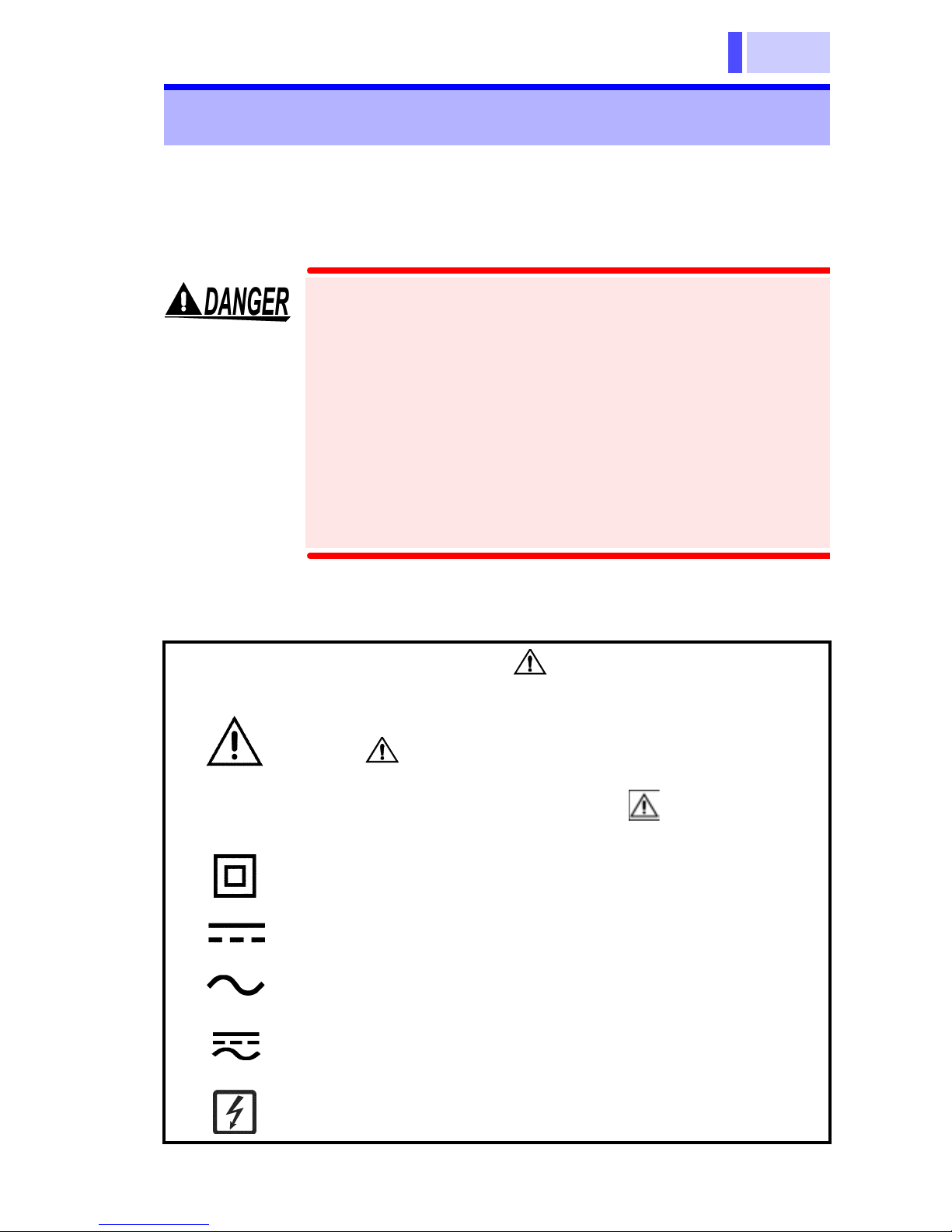
Safety Symbols
In the manual, the symbol indicates particularly important information that the user should
read before using the product.
The symbol printed on the product indicates
that the user should refer to a corresponding topic
in the manual (marked with the symbol) before
using the relevant function.
Indicates a double-insulated device.
Indicates DC (Direct Current).
Indicates AC (Alternating Current).
Indicates both DC (Direct Current) and AC (Alternating Current).
Indicates that the instrument may be connected to
or disconnected from a live circuit.
Page 10
4
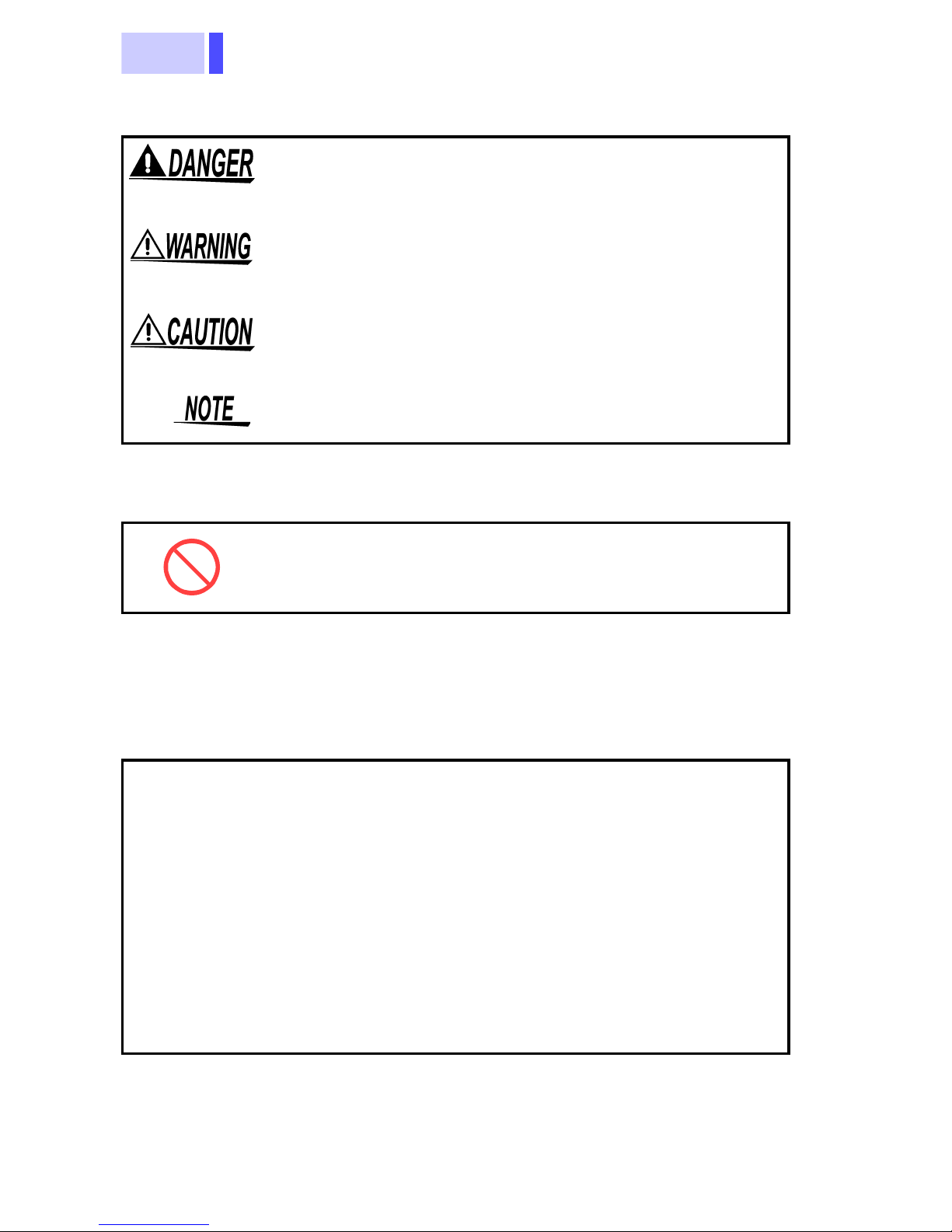
The following symbols in this manual indicate the relative
importance of cautions and warnings.
Indicates that incorrect operation presents an extreme hazard that could result in serious injury or
death to the user.
Indicates that incorrect operation presents a significant hazard that could result in serious injury or
death to the user.
Indicates that incorrect operation presents a possibility of injury to t he user or damage to the product.
Advisory items related to performance or correct
operation of the product.
Other Symbols
Indicates the prohibited action
Accuracy
We define measurement tolerances in terms of f.s. (full
scale), rdg. (reading) and dgt. (digit) values, with the
following meanings:
(maximum display value or scale length)
f.s.
rdg.
The maximum displayable value or the full length
of the scale. This is usually the maximum value of
the currently selected range.
(reading or displayed value)
The value currently being measured and indicated
on the measuring product.
(resolution)
dgt.
The smallest displayable unit on a digital measuring product, i.e., the input value that causes the
digital display to show a "1".
Page 11
5
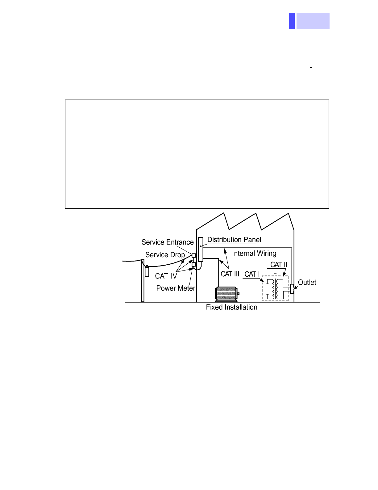
Measurement categories (Overvoltage categories)
This product complies with CATIII (600 V), CATII (1000 V)
safety requirements.
To ensure safe operation of measurement products, I
61010 establishes safety standards for various electrical
environments, categorized as CAT I to CAT IV, and called
measurement categories. These are defined as follows.
EC
CAT I
CAT II
CAT III
CAT IV
Secondary electrical circuits connected to an AC electrical outlet through a transformer or similar device.
Primary electrical circuits in equipment connected to an
AC electrical outlet by a power cord (portable tools,
household appliances, etc.)
Primary electrical circuits of heavy equipment (fixed installations) connected directly to the distribution panel,
and feeders from the distribution panel to outlets.
The circuit from the service drop to the service entrance,
and to the power meter and primary overcurrent
protection device (distribution panel).
Higher-numbered categories correspond to electrical
environments with greater momentary energy. So a
measurement device designed for CAT III environments
can endure greater momentary energy than a device
designed for CAT II.
Using a measurement product in an environment
designated with a higher-numbered category than that for
which the product is rated could result in a severe
accident, and must be careful ly avo ided .
Never use a CAT I measuring iproduct in CAT II, III, or IV
environments.
The measurement categories comply with the
Overvoltage Categories of the IEC60664 Standards
Page 12
6
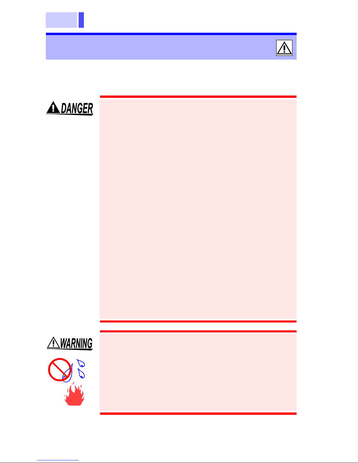
Usage Notes
Follow these precautions to ensure safe operation and to
obtain the full benefits of the various functions.
• To avoid short circuits and potentially life-
threatening hazards, never attach the
product to a circuit that operates at more
than the 600V, or over bare conductors.
• Clamp sensor should only be connected to
the secondary side of a breaker, so the
breaker can prevent an accident if a short
circuit occurs. Connections should never
be made to the primary side of a breaker,
because unrestricted curr ent flo w could
cause a serious accident if a short circuit
occurs.
• Use only the specified Model 9445-02 AC
ADAPTER (SA10-0910N, SINO-AMERICAN) or 9445-03 (for EU) AC ADAPTER
(SA10-0910G, SINO-AMERICAN).
AC adapter input voltage range is 100 to
240 VAC (with ±10% stability ) at 50/60 Hz.
To avoid electr ica l h az ards an d da ma ge to
the product, do not apply voltage outside of
this range.
• To avoid electric shock, do not allow the
product to get wet, and do not use it when
your hands are wet.
• Do not use the product where it may be
exposed to corrosive or combustible
gases. The product may be damaged or
cause an explosion.
Page 13

7
• The top part of the clamp sensor above the
barrier (including the clamps, but not the
lever) is provided with double insulation to
ensure safety. Be careful not to drop the
sensor or othe rwis e s ub jec t i t to im p act. A
damag ed sens or may result in el ectric
shock during measurement. In case of
sensor damage, contact us immediately for
repa ir or disc ard the dam ag ed se nso r to
avoid su bse qu ent use .
• To avoid damage to the product, do not
exceed the maximum input current rating,
which depends on the frequency of the
current being measured (see Chapter 8
Clamp Sensor Specifications - Frequencydependent del eti on cha r ac teri sti cs) Be
careful about the evolution of heat, when
the input frequ enc y is high.
• To avoid electri c s ho ck when rep lac in g th e
batteries, first disconnect the clamp from
the object to be measu red.
• After replacing the batteries, replace the
cover and screws before usi ng the
product.
• Do not mix old and new batteries, or
different types of batteries. Also, be careful
to observe battery polarity during
installation. Otherwise, poor performance
or damage from battery leakage could
result.
• To avoid the possibility of explosion, do not
short circuit, disassemble or incinerate
batteries.
• Handle and dispose of batteries in
accordance with local regulations.
Page 14

8
• Do not use the product when the battery is
depleted ( lights on the LCD). When
is on, accuracy and other specifications cannot
be guaranteed.
• For the inside memory prot ection, make sure
the power is turned off before plugging in or
unplugging the AC adapter.
• Adjust ments and repairs should be made only
by technically qualified personnel.
• If the protective functions of the product are
damaged, either remove it from service or mark
it clearly so that others do not use it inadvertently.
• To avoid corrosion from batter y leakage, remo ve
the batteries from the product if it is to be stored
for a long time.
Page 15
9
Observe the following to avoid damage to the
-
st
-
n
n
product.
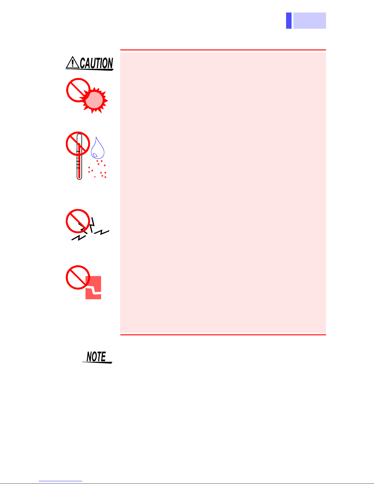
• Installation and Operating Environment
Between 0°C and 40°C; 80% RH or less;
indoors only.
Direct
sunlight
High temper
ature, high
humidity, du
Electromag
etic radiatio
• Do not store or use the product where it could
be exposed to direct sunlight, high temperature
or humidity, or condensation. Under such conditions, the product may be damaged and insulation may deteriorate so that it no longer meets
specifications.
• This product is not designed to be entirely
water- or dust-proof. To avoid damage, do not
use it in a wet or dusty environment.
• Do not use the product near a device that generates a strong electromagnetic field or electrostatic charge, as these may cause erroneous
measurements.
• To avoid damage to the product, protect it from
vibration or shock during transport and handling,
and be especially careful to avoid dropping.
Impact,
dropping
• Accurate measurement may be impossible in the
• To clean the product, wipe it gently with a soft
presence of strong magnetic fields, such as near
transformers and high-current conductors, or in
the presence of strong electromagnetic fields
such as near radio transmitters.
cloth moistened with water or mild detergent.
Never use solvents such as benzene, alcohol,
acetone, ether , ketones, thinners or gasoline, as
they can deform and discolor the case.
Page 16

10
Organization of This Manual
Chapter 1 Product Ov erview
Provides an overview of the product and describes the
parts and functions.
Chapter 2 Basic Measurement Procedure
Describes the basic measurement procedure for quick
reference and the peak measurement procedure in DC
current (DC A) mode, AC current (AC A) mode, and
AC+DC A mode.
Chapter 3 Measurement Procedure
Describes the measurement procedure for the 3290
CLAMP ON AC/DC HiTESTER when combined with the
9691, 9692, or 9693 CLAMP ON AC/DC SENSOR.
Chapter 4 Battery Replacement
Explains how to replace the battery used for the 3290
Clamp On AC/DC HiTESTER.
Chapter 5 AC Adapter
Explains how to use the 9445-02 AC Adapter (optional).
Chapter 6 Attaching the Strap
Explains how to attach the strap.
Chapter 7 Specifications
Lists the specifications of the 3290 CLAMP ON AC/DC
HiTESTER.
Chapter 8 Clamp Sensor Specifications
Lists the specifications of the 9691, 9692, and 9693
CLAMP ON AC/DC SENSORs.
Chapter 9 Carrying Case
Explains how to use the 9400 CARRYING CASE
(optional).
Page 17

11
Chapter 10 Troubleshooting
Lists common symptoms that may indicate a malfunction.
If you encounter a problem, be sure to read this chapter
before requesting repair.
Chapter 11 Service
Describes our customer support service.
Chapter 12 Appendix
• Provides the accuracy table and explains how to
calculate accuracy for the 3290 CLAMP ON AC/
DC HiTESTER when combined with the 9691,
9692, or 9693 CLAMP ON AC/DC SENSOR.
• Describes how to use the intermediate cable.
Page 18

12
Page 19

13
Chapter 1 Overview
Overview Chapter 1
1.1 Product Overview
The 3290 CLAMP ON AC/DC HiTESTER is used with the
9691, 9692, or 9693 CLAMP ON AC/DC SENSOR.
These sensors are interchangeable and any model can
be used with the 3290. The 3290 automatically detects
the sensor connected and sets up the appropriate range.
When combined with the 9691, 9692, or 9693 Sensor, the
3290 HiTESTER can perform DC, AC, and AC+DC
measurement of a live power line. Various functions are
available (using the SHIFT key) to make the 3290 suitable
for various current measurement applications. The 3290
is also equipped with two output terminals to enable a
variety of advanced measurements, such as simultaneous
output of both monitor and rms record. Moreover, the
3290 can operate using battery power or the AC adapter
(for long-term measurement use).
1.2 Features
The 3290 has the following features:
Multif unc tion Microcom puter
The 3290 both compact and multifunctional thanks to the
built-in microcomputer and use of the SHIFT key.
Large-Screen LCD
The large-screen LCD employed is easy to read.
Clamp Sensor
The 3290 is compatible with three clamp-on AC/DC
sensors (9691, 9692, and 9693) having different ratings.
Because the 3290 automatically detects the sensor
connected, you need not edit the setting each time you
change the sensor.
Page 20

Chapter 1 Overview
14
Multif unc tion Microcom puter
The 3290 both compact and multifunctional thanks to the
built-in microcomputer and use of the SHIFT key.
Large-Screen LCD
The large-screen LCD employed is easy to read.
Clamp Sensor
The 3290 is compatible with three clamp-on AC/DC
sensors (9691, 9692, and 9693) having different ratings.
Because the 3290 automatically detects the sensor
connected, you need not edit the setting each time you
change the sensor.
Two Output Terminals
Two signals are output simultaneously from among the
four following: current (REC = record and MON =
monitor), current frequency (REC = record), and low
battery warning signal.
• Current monitor & low battery warning signal
• Current monitor & current record
• Current record & low battery warning signal
• DC component & AC component (AC/DC separate output)
• Frequency record & current record
Method of measurement
In AC A mode, you can select either the true rms (RMS)
or average rectified rms indication (MEAN).
Measurement Response Speed
For RMS measurement, you can select a response speed
from FAST, NORMAL, or SLOW.
Low-frequency Current Measurement
In AC+DC A mode, you can measu re curr en t from 1 Hz
when the measurement response speed is set to SLOW.
Filter Function
This function turns on and off a low-pass filter (LPF) of
approximately 500 Hz.
Setting Save Function
This function saves the current measurement conditions
so that settings are retained even after power is turned
OFF.
Key Lock Function
This locks all keys including the POWER key (except the
keys used to unlock).
Page 21

15
Chapter 1 Overview
AC+DC Measurement
The 3290 measures AC superimposed on DC, half-wave
rectified, and full-wave rectified.
Peak Measurement
The peak hold current can also be measured.
REC Function
You can select whether the maximum or minimum
measurement value is displayed.
Dual-power supply
The 3290 run s on either battery power or an AC power
source.
Dustproof Cap
The dustproof cap is provided for use in a dusty
environment.
Intermediate Cable
In case the 9691, 9692, or 9693 sensor cable (about 2 m
long) is too short, an interme diate cable can be used to
extend connection length. Insert the intermediate cable
between the 3290 and the sensor cable.
Page 22
Chapter 1 Overview
16
5,
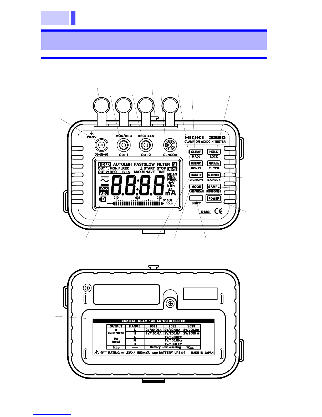
1.3 Parts Names and Functions
1.3.1 3290 CLAMP ON AC/DC HiTESTER
21
24
22
23
27
20
14
6,
11
7,15
8,16
9,17
10,18
1
28
19
4,
13
3,
12
2
Page 23
17
26
25
Chapter 1 Overview
Keys for Basic Measurement
1. POWER Key
• Turns power ON/OFF.
• Holding down the CLEAR key and turning power
on initializes the setting save function and
restores the default settings.
• Holding down the HOLD key and turning power
on disables the auto power-off function.
• Holding down the PEAK/Hz key and turning
power on turns off the buzzer.
2. SHIFT Key
• Pressing this key causes to light, indicating
that the additional function (in blue letters) allo-
cated to each key is available. To turn off,
press the SHIFT key again.
• Some keys may be locked when is on.
Page 24
Chapter 1 Overview
18
3. MODE Key
• Selects the current measurement mode.
4. RANGE Key
• Selects auto range or manual range.
• Selects a measurement range when manual
range is selected.
• The current ranges for the 9691 and 9692 are 20
A and 200 A; the ranges for the 9693 are 200 A
and 2000 A. The frequency ranges are 10 Hz,
100 Hz, and 1000 Hz.
5. OUTPUT Key
• Sets the output (for current and frequency measurement).
Two outputs are available. The settings available for each current measurement mode are
fixed.
AUTO
AC ADC A
L
M
(Hz only)
AC+DC A
H
• Disables the auto power-off function.
6. CLEAR Key
• Clears data to “0” during peak measurement.
• Clears data to “0” during activation of the recording function.
• Holding down the CLEAR key and turning power
on initializes the setting save function and
restores the default settings.
7. HOLD Key
• Suspends or deactivates the screen-updating
function. (See 15 under “Keys for Advanced
Measurement” for details of the key lock function.)
• Holding down the HOLD key and turning power
on disables the auto power-off function.
Page 25
19
8. PEAK/Hz Key
• PEAK performs peak measurement of waveforms (peak hold).
• Hz performs frequency measurement (in AC A
mode).
• Holding down the PEAK/Hz key and turning
power on turns off the buzzer.
9. MAX/MIN Key
• Activates the recording function and displays the
maximum value (MAX), minimum value (MIN),
mean value of both maximum & minimum values
(AVE), and elapsed time (TIME).
• Pressing this key immediately activates the
recording function.
• MAX displays the maximum value of measurements taken after the recording function is activated.
Chapter 1 Overview
• MIN displays the minimum value of measurements taken after the recording function is activated.
• AVE displays the mean value of the maximum
and minimum values measured after the recording function is activated.
• TIME displays the time elapsed after the recording function is activated.
• The auto power-off function is deactivated.
10. SAMPL Key
• Selects a screen-updating rate from NORMAL
(twice/sec.), SLOW (once/3 sec. ), or FAST (4
times/sec.). Each time this key is pressed, the
rate changes in the order above.
MINMAX
TIMEAVE
Measurement
value
• The rate is usually set to NORMAL. (Note that
• SLOW decelerates the speed of updating on-
• FAST accelerates the speed of updating on-
there is no indication for NORMAL.)
screen measurement (with SLOW on).
screen measurement (with FAST on).
Page 26
Chapter 1 Overview
20
• During RMS measurement in AC mode or when
in AC+DC mode (with RMS on), the measurement response speed changes according to the
screen-updating rate (SLOW, FAST, or NORMAL).
• Y ou can only change the measurement response
speed. For details, see 18 under “Keys for
Advanced Measurement.”
NORMAL
SLOW
FAST
11. 0 ADJ Key (SHIFT CLEAR Keys)
• Performs auto zero adjustment in DC A or
AC+DC A mode.
Keys for Advanced Measurement
12. RMS/MEAN Key (SHIFT MODE Keys)
• Selects the true rms measurement (RMS) or
average rectified rms indication (MEAN) in AC A
mode. RMS provides accurate measurement of
distorted waveforms. MEAN only provides accurate measurement of undistorted sine waves.
13. B.GRAPH Key (SHIFT RANGE Keys)
• Enlarges the range of a bar graph.
14. MON.FL Key (SHIFT OUTPUT Keys)
• Turns on a low-pass filter of approx. 1 Hz when
MON is selected for OUT1 in DC A mode.
• Turns on a low-pass filter of approx. 1 Hz when
MON is selected for OUT1 (REC for OUT2) in
AC+DC A mode. This enables separate output
of the DC component (OUT1) and AC component (OUT2). (The value of the AC component is
indicated on the LCD.)
Page 27

21
Chapter 1 Overview
15. LOCK Key (SHIFT HOLD Keys)
• Locks all keys including the POWER key.
• To unlock, press the same keys again (SHIFT
HOLD keys).
16. FILTER Key (SHIFT PEAK/Hz Keys)
• Turns on a low-pass filter of approx. 500 Hz in
AC A or AC+DC A mode .
• To turn the filter off, press the same keys again
(SHIFT PEAK/H z key s).
17. B.CHECK Key (SHIFT MAX/MIN Keys)
• Indicates remaining battery power. When power
is depleted to 0%, the low battery warning ( )
goes on.
18. RESPONSE Key (SHIFT SAMPL Keys)
Display
19. LCD
• Selects a measurement response speed independently from the screen-updating rate when
RMS is selected in AC A mode or when AC+DC
mode is selected.
• Press the SAMPL key to return to the measurement response speed that matches the selected
screen-updating rate.
The letter of LCD is clearest, when it sees from the front
side.
Page 28
Chapter 1 Overview
22
Direct Current (DC)
Alternating Current (AC)
Alternating Current and Direct Current (AC+DC)
Auto zero adjustment is active.
Low battery war ning
OUT1 Setting of OUT1
OUT2 Setting of OUT2
Data hold function
MON
MON.FL
Monitor is active.
1 Hz filter for monitor is active.
REC Record is active.
Auto power-off is active.
AUTO Auto-range
L Current/frequency low range
M Frequency mid range
H Current/frequency high range
FAST Screen-updating 4 times/sec.
SLOW Screen updating approx. once/3 sec.
FILTER 500 Hz filter is active.
MAX Maximum value
MIN Mini mum value
AVE Average value
TIME Elapsed time
MEAN Average rectified rms indication
RMS True root mean squar e value
PEAK Wave peak value
Hz Frequency
Key lock is active.P
A Current
hour 100 hours/segment (bar graph)
Input over (bar graph)
SHIFT
Page 29

23
Chapter 1 Overview
Parts
20. Sensor Connector (SENSOR)
Connect the 9691, 9692, or 9693 CLAMP ON AC/DC
SENSOR to this connector.
21. AC Adapter Connection Terminal
Connect the 9445-02 AC ADAPTER (optional) to this
terminal when not using the battery or for long-term
measurement.
22. Output Terminal 1 (OUT1)
Connect the 9094 OUTPUT CORD (optional) to this
terminal to obtain output during current or frequency
measurement.
23. Output Terminal 2 (OUT2)
Connect the 9094 OUTPUT CORD (optional) to obtain
output during current measurement or at detection of the
low battery warning signal.
24. Dustproof Caps (4 pcs.)
Used to protect the terminals in a dusty environment.
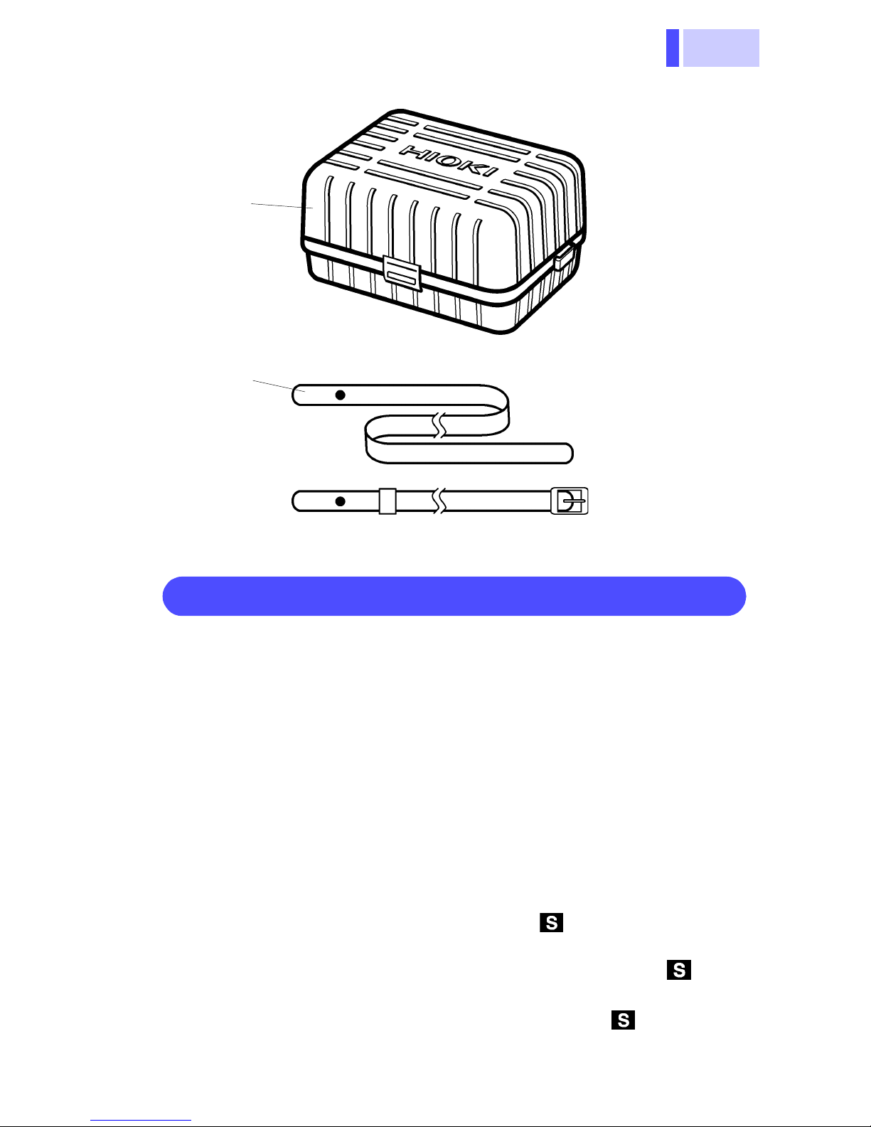
25. Strap
Used to hang the 3290 around neck so as not to drop it.
26. Top Case
Cover the 3290 with this case when not in use to protect
the LCD, keys and terminals.
27. Top Case Clasp
Insert the clasp into the top case to attach the case. Move
the top case to the rear during measurement.
28. Battery Cover
Unfasten the screw, then remove the case to replace the
battery.
Page 30
Chapter 1 Overview
24
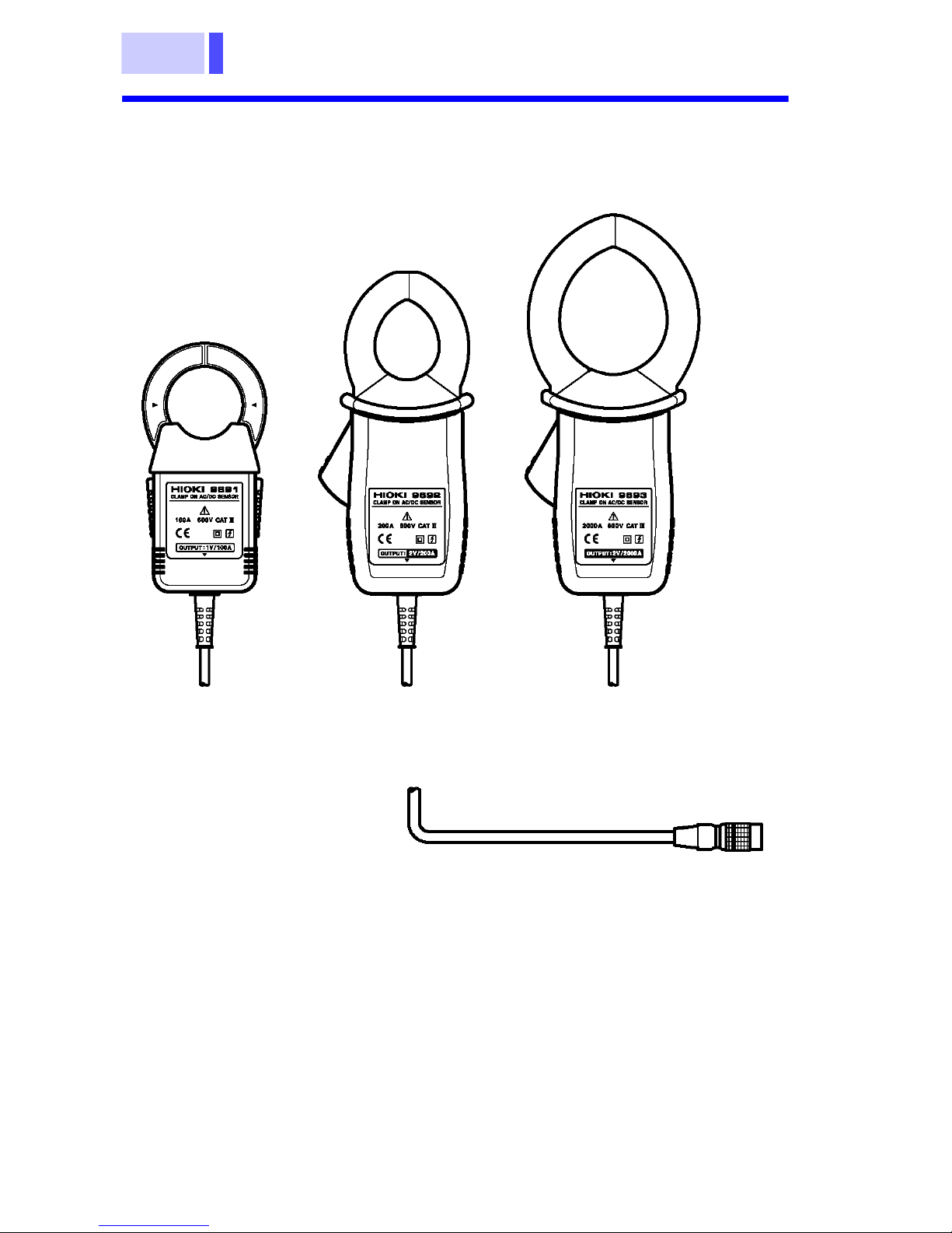
1.3.2 9691, 9692, 9693
CLAMP ON AC/DC SENSOR
9691
9692
9693
Output connector
Page 31

25
Chapter 1 Overview
R
M
1.4 Flowchart Of Key Operations
1.4.1 Current Measurements Mode
MODE key
AC ADC A
ANGE key
AC+DC A
PEAK/Hz key
AX/MIN key
AUTO range
L range
H range
DC A
PEAK
MAX
AUTO range
L range
H range
AC A
PEAK
Hz
MAX
AUTO range
L range
H range
AC+DC A
PEAK
MAX
MIN
AVE
TIME
Measured
value
MIN
AVE
TIME
Measured
value
MIN
AV E
TIME
Measured
value
Page 32

26
S
R
MODE key
Chapter 1 Overview
DC A
AC A
AC+DC A
OUTPUT key
AMPL key
MS/MEAN key
OUT1 OUT2
OFF OFF
MON B.Lo
NORMAL
SLOW
FAST
Disabled
OUT1 OUT2
OFF OFF
REC B.Lo
MON REC
NORMAL
SLOW
FAST
OUT1 OUT2
OFF OFF
REC B.Lo
MON REC
NORMAL
SLOW
FAST
Disabled
RMS
MEAN
Page 33

27
Chapter 1 Overview
MODE key
MON.FL key
FILTER key
RESPONSE キー
MON
MON.FL
Disabled
Disabled
AC ADC A
Disabled
OFF
ON
NORMAL
(No displayed)
AC+DC A
MON
MON.FL
OFF
ON
NORMAL
(No displayed)
SLOW ( )
FAST ( )
Effective on RMS
SLOW ( )
FAST ( )
Page 34

Chapter 1 Overview
28
1.4.2 Frequency Mode
PEAK/Hz key
RANGE key
MAX/MIN key
PEAK
AUTO range
L range
H range
MAX
MIN
Hz
(AC A only)
AUTO range
10.00 Hz(L) range
100.0 Hz(M) range
1000 Hz(H) range
MAX
MIN
Current
Measured
value
OUTPUT key
AV E
TIME
Measured
value
OUT1 OUT2
OFF OFF
MON B.Lo
AVE
TIME
Measured
value
OUT1 OUT2
OFF OFF
REC (Hz) REC(A)
Page 35

29
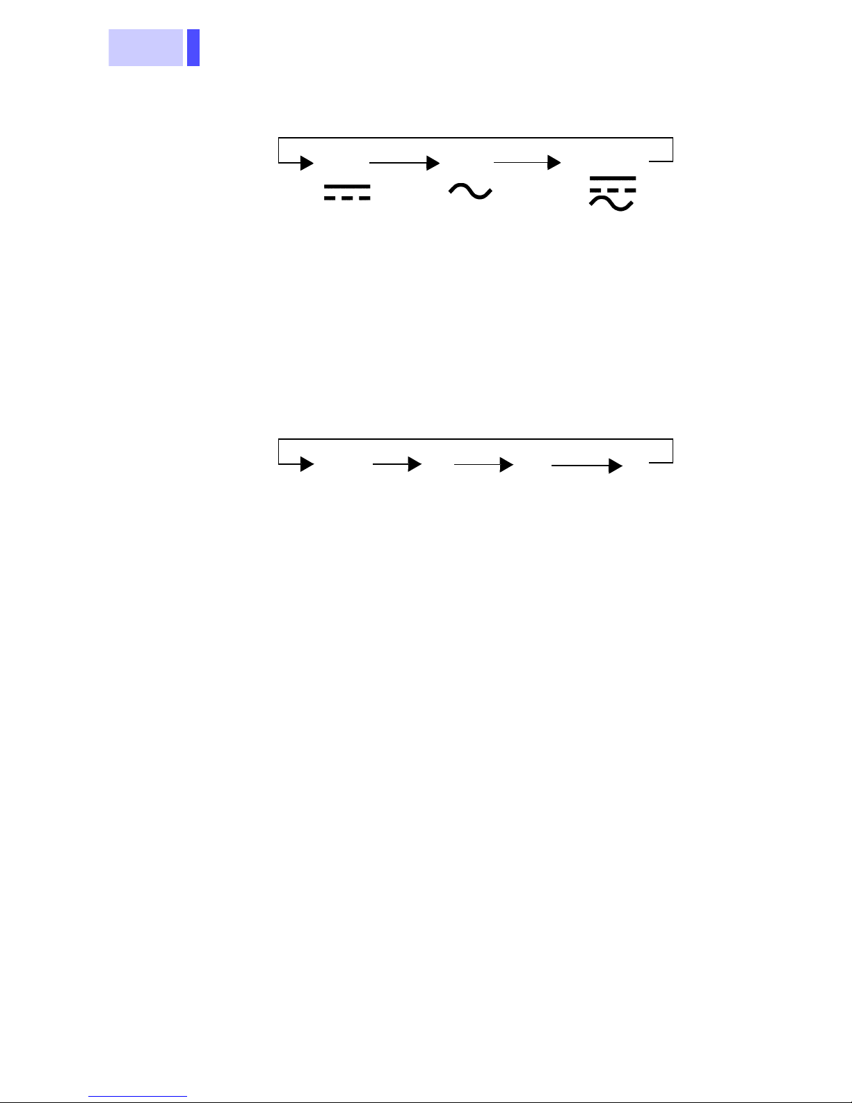
1.5 Modes
For current, three modes are provided: DC (direct current,
), AC (alternating current, ), and AC+DC (alternating
current and direct current, ) modes. Select a proper
mode according to the waveform shown below:
Chapter 1 Overview
0
0
0
0 V
0
0
0
0
0
0
0
0
0
0 V
0
0
0
0
0
0
0
0
0
0
0
0
Page 36

30
Mode
Chapter 1 Overview
Input
Display
waveform
OK
(with polarity)
OUTPUT
(only for current mode)
REC MON
DC
()
AC
()
No
Not meas urab le
No
Not measurable
No
Not meas urab le
(zero displayed)
OK
No
Not measurable
OK
(without
polarity)
Setting
impossible
AC+DC
()
OK
OK
Page 37

31
Chapter 1 Overview
-
-
-
-
-
-
-
-
-
-
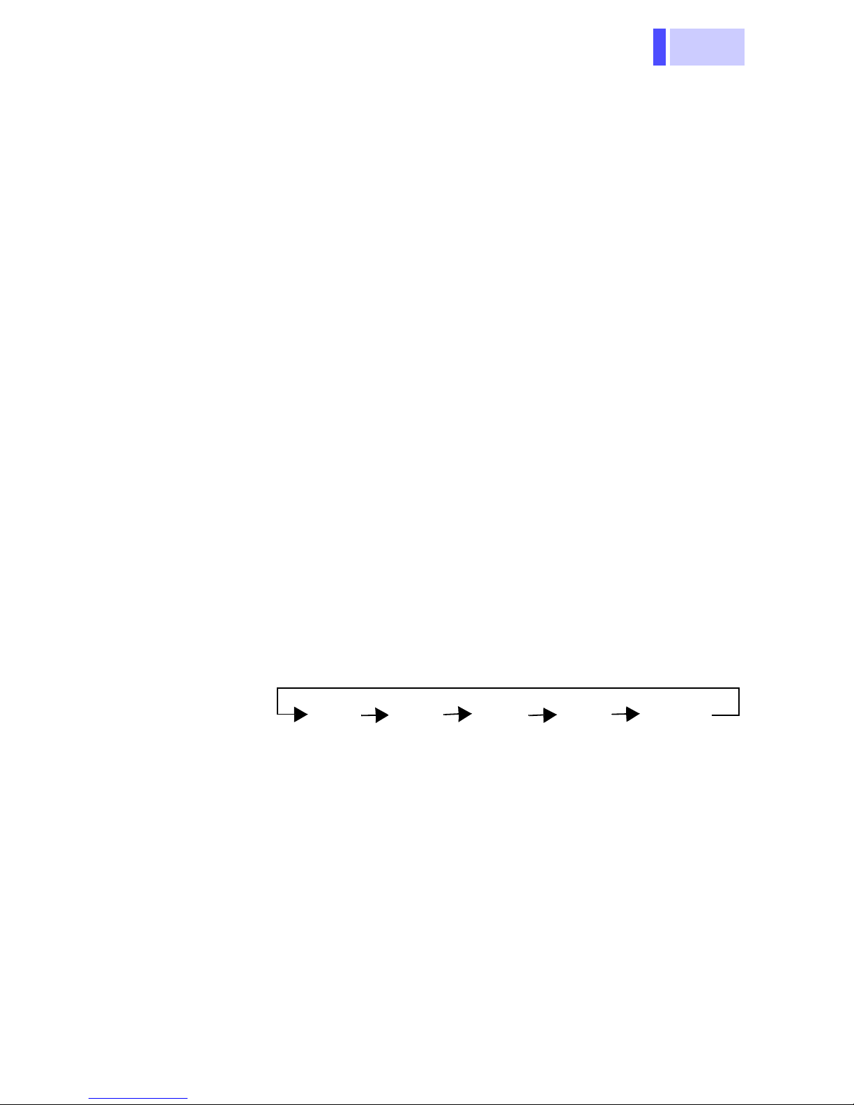
Quick Reference
Measurements Operations
DC A
AC A RMS
AC A MEAN
AC+DC A
DC A peak
PEAK
ADJ
→
RMS
→
MEAN
→
ADJ
→
ADJ
→
Measure
ment
Measure
ment
Measure
ment
Measure
ment
Measure
ment
(pa g e)
44
45
46
47
49
AC A RMS
peak
AC A MEAN
peak
AC+DC A
peak
AC A RMS
Hz
AC A MEAN
Hz
RMS
MEAN
PEAK
RMS
MEAN
→
→
→
→
PEAK
PEAK
ADJ
→
Hz
Hz
Measure
49
ment
49
Measure
ment
49
Measure
ment
55
Measure
ment
55
Measure
ment
Page 38

Chapter 1 Overview
32
/peak/
H
/peak/
H
W
i
/peak/
H
/peak/Hz
/peak/
H
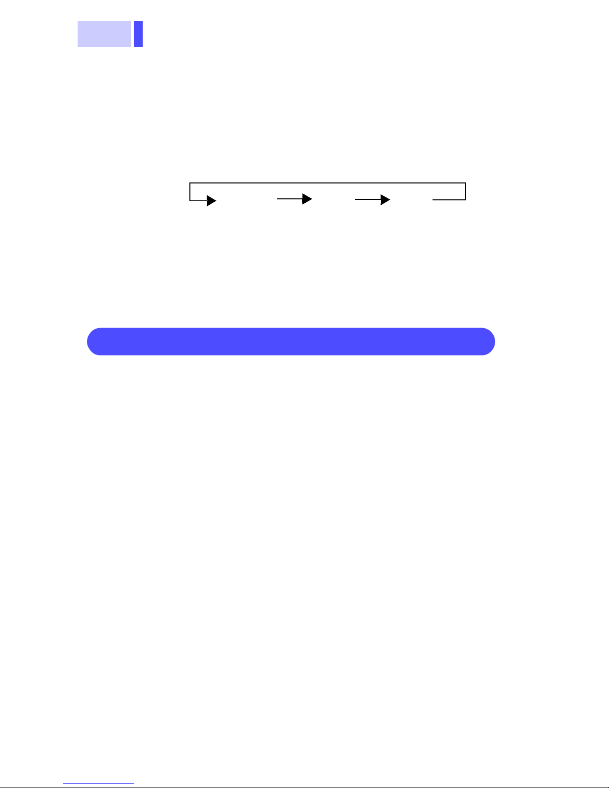
Quick Reference (application)
Operations
(page)
Hold the measured value (Data Hold Function)
//
z/record
Measurement
HOLD
59
"O.L." is displayed (Overflow Warning Function)
//
z/record
hen the measured value exceeds the max-
mum value, "O.L." is displayed.
−
Change the screen update rate
(Changing the Screen Update Rate)
//
(NORMAL/SLOW/FAST) switch
59
z
Measurement speed can be changed
(Measurement Response Speed Switching Function)
/
Outputs (Output Function)
//
z
(NORMAL/SLOW/FAST) switch
→
AC A mode: RMS
AC+DC A mode only
OUT1: OUT2: on
65
51
56
Page 39

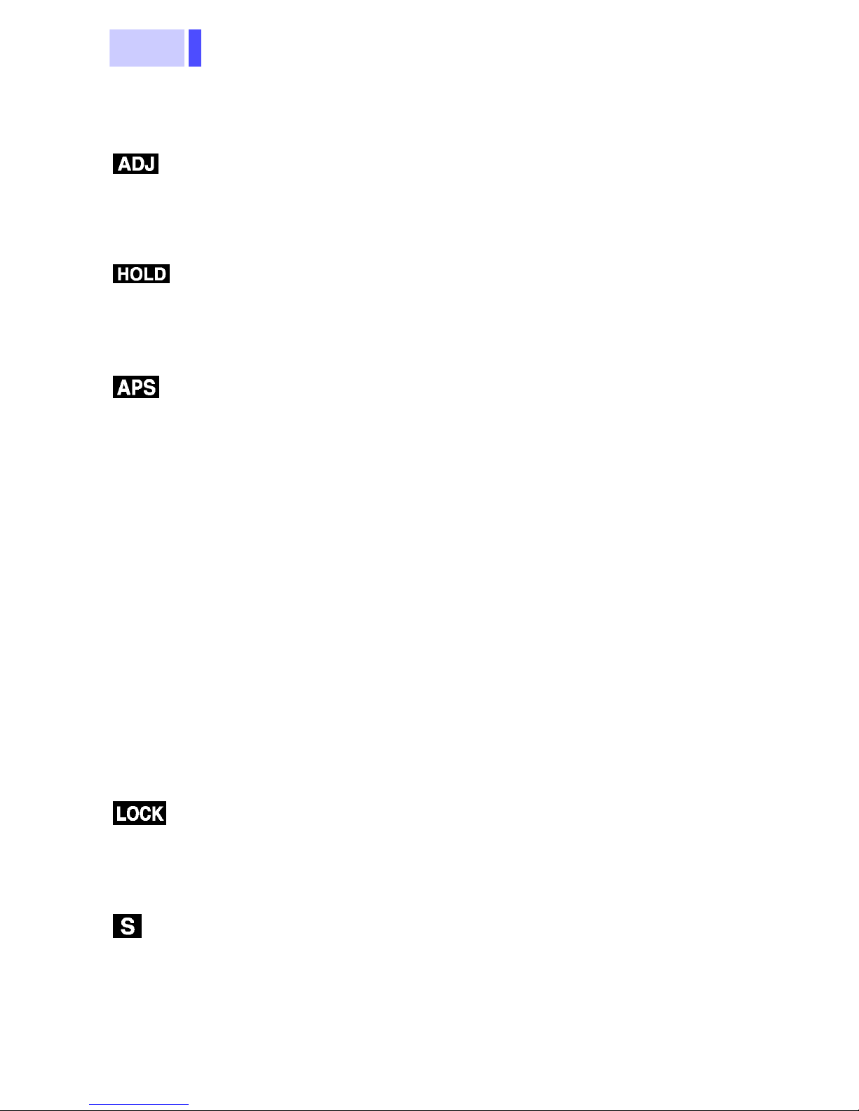
33
Chapter 1 Overview
O
O
D
/peak
/
/peak/
H
/peak/
H
/peak/
H
Operations
(page)
Obtained through a low-pass filter (LPF) set to approximately 1
Hz (MON Output Filter Function)
/
UT1:
MON
UT2:
REC
isable:
→
→
OUT1:
MON.FL
OUT2:
REC
Press the key
again.
71
Obtained through a low-pass filter (LPF) to measurement
value and output. (Filter Function)
/
→
FILTER : on
68
500 Hz の Hz
Disable:
→
Press the key
again.
Disabling the auto power off function (Auto Power Off Function)
//
z
+
Power ON
APS : O FF
72
Disabling the beep tone (Beep Tone)
//
z
+
Power ON
75
Hold the maximum measurement, minimum measurement, and
mean value. (Recording Function)
//
z/record
Bar graph
The elapsed
time is
displayed.
MAX: maximum value /MIN: minimum value
/AVE: average value /TIME: elapsed time
(MAX/MIN/AVE/
TIME/
Instantaneous
value switch
61
Disable:
Press the key.
Page 40

Chapter 1 Overview
34
/peak/
H
D
" " display
/Hz
/peak/
H
/peak/
H
on
Operations
(page)
Saved the settings (Setting the Save Function)
//
73
z
(Hold down 2 seconds. )
isable:
+
Power ON
"" ""
display
Enlarged to the Bar graph. (Bar Graph Enlargement Function)
//
→
Disable:
Bar Graph Enlargement
→
Press the key
again.
69
Battery check
//
z/record
Key lock
//
z
→
→
Disable:
→
70
69
Press the key
again.
Page 41

35
Chapter 2 Basic Measurement Procedures
Basic
Measurement
Procedures
• To avoid short circuits and potentially lifethreatening hazards, never attach the
product to a circuit that operates at more
than the 600V, or over bare conductors.
• Clamp sensor should only be connected to
the secondary side of a breaker, so the
breaker can prevent an accident if a short
circuit occurs. Connections should never
be made to the primar y side of a breaker,
because unre stri ct ed current flow cou ld
cause a serious accident if a short circuit
occurs.
• Use only the specified Model 9445-02 AC
Chapter 2
ADAPTER (SA10-0910N, SINO-AMERICAN) or 9445-03 (for EU) AC ADAPTER
(SA10-0910G, SINO-AMERICAN).
AC adapter input voltage range is 100 to
240 VAC (with ±10% stability ) at 50/6 0 H z.
To avoid electri ca l ha za rds and damage t o
the product, do not apply voltage outside of
this range.
This chapter describes t he basic meas urement
procedure. For details of the measurement procedure, see Chapter 3, “Measurement Procedure.”
Page 42

Chapter 2 Basic Measurement Procedures
36
2.1 DC Measurement (DC A)
1. Press the MODE key to
display DC A ( ).
2. Press the SHIFT key to
display .
Page 43

37
Chapter 2 Basic Measurement Procedures
.
3. Press the 0 ADJ key
(CLEAR key) to perform
zero adjustment.
4. will appear on the
LCD.
9691 CLAMP ON AC/DC SENSOR
Load
Measured
conductor
Power
source
5. Align the current direction
indicator on the clamp
with the current directio n
of the conductor to be
measured, then clamp
the conduct or so that it
passes through the
center of the clamp core.
The figure shows the
9691 CLAMP ON AC/DC
SENSOR. When using
the 9692 or 9693 CLAMP
ON AC/DC SENSOR,
note that the current
direction indicator is
located in a different
position.
6. Read the displayed value
Since the measurem en t
range is set to AUTO, you
need not set the range.
Page 44

Chapter 2 Basic Measurement Procedures
38
.
2.2 AC Measurement (AC A)
1. Press the MODE key to
display AC A (
* When measuring
current up to 10 Hz, use
AC+DC A mode and
select SLOW.
).
9691 CLAMP ON AC/DC SENSOR
Measured
conductor
2. Clamp the conductor to
be measured so that it
passes through the
center of the clamp core.
You need not align the
direction of the clamp.
3. Read the displayed value
Since measurem ent
range is set to AUTO, you
need not set the range.
Page 45

39
Chapter 2 Basic Measurement Procedures
2.3 Peak Measurement
In AC+DC A Mode
1. Press the MODE key to
display AC+DC A ( ).
2. Press the PEAK/Hz to
display PEAK.
Page 46

Chapter 2 Basic Measurement Procedures
40
3. Press the SHIFT key to
display .
9691 CLAMP ON AC/DC SENSOR
Measured
conductor
4. Press the 0 ADJ key
(CLEAR key) to perform
zero adjustment.
5. will appear on the
LCD.
6. Clamp the conductor to
be measured so that it
passes through the
center of the clamp core.
You need not align the
direction of the clamp.
Page 47

41
Chapter 2 Basic Measurement Procedures
.
7. Press the CLEAR key (0
ADJ key) to clear the
data.
8. Read the displayed value
Since the measurem en t
range is set to AUTO, you
need not set the range.
Page 48

Chapter 2 Basic Measurement Procedures
42
Page 49

43
Chapter 3 Measurement Procedures
Measurement
Procedures
• Do not connect or disconnect the output connector of the clamp-on sensor while power is
supplied to the 3290 or the sensor is clamping a
conductor to be measured.
• When disconnecting the output connector of the
clamp-on sensor from the 3290 sensor connector , be sure to hold it by the metal part and pull it
upward. If it is pulled by the cable, the lock will
not be released and a broken wire in the cable
may result.
• The maximum continuous-input limit is obtained
from the temperature increase due to self-heating during measurement. To prevent damage to
Chapter 3
the clamp-on sensor, do not input a current
exceeding this limit.
• The max imum continuous-input limit varies
depending on the clamp-on sensor and the frequency of the current to be measured. Please
see the dilating-characteristics graph by frequency in "Chapter 8 Clamp Sensor Specifications".
3.1 Preparations
1. Remove the battery cover and insert the bat-
tery (see Chapter 4 Battery Replacement).
2. Connect the output connector of the clamp-on
sensor to the sensor connector. The type of
clamp-on sensor will be detected automatically.
Page 50

Chapter 3 Measurement Procedures
44
3. Press the POWER key to turn on the power.
Make sure all segments of the LCD light up.
Then, the model No. (3290) is displayed and
the charge remaining in the battery is shown
by a bar graph.
New battery
50% battery charge
The battery charge is 0.
lights up.
The beep tone sounds three
times.
remaining
4. The 3290 is ready for operation in DC-current
measurement mode.
• If the setting save function has been used (if the
HOLD key is held down for approximately 2 seconds, the current setting is saved), the 3290 will
be in the saved measurement mode.
• To cancel the saved setting, turn off the power
and then turn it on again while holding down the
CLEAR key. The 3290 will return to the default
setting (DC current).
Low-Battery-Voltage Detection Function
If the battery voltage falls when is on, the power will be
turned off. On the LCD, “ ” and “ ” will appear.
Connecting/Disconnecting the Clamp On Sensor
When connecting the clamp-on sensor to the 3290, hold it
by the area above the metal part of the output connector
when inserting it. If it is held by the metal part, it won’t be
possible to insert the output connector into the sensor
connector. Make sure the wide terminal of the connec tor
is at the top when the connector is inserted.
When disconnecting the clamp-on sensor from the 3290,
hold the metal part of the connector when pulling it out. If i t
is held by the area above the metal part, it won’t be
possible to disconnect the connector.
Page 51

45
Chapter 3 Measurement Procedures
Wide termina l
Connecting
Disconnecting
3.2 Current Measurement
• The ends of the clamp sensor are very delicate.
Be careful not to drop the sensor or subject it to
impact. If the sensor is deformed or the contact
surfaces of the clamps are damaged, the measurement may not be accurate.
• Be sure to read the instruction manual for the
clamp sensor to be used before starting measurement.
Output connector
• The hall element is used for the detector of the
• Accurate measurement may be impossible in the
clamp-on sensor. The hall element tends to drift
with age or due to the ambient temperature.
Keep this fact in mind when performing measurement continuously.
presence of strong magnetic fields, such as near
transformers and high-current conductors, or in
the presence of strong electromagnetic fields
such as near radio transmitters.
Page 52

Chapter 3 Measurement Procedures
46
• The reading may show a measurement greater
than the actual value due to magnetic-field interference. The amount of interference varies
depending on the sensor. For detail s, see “External magnetic-field interference” in Chapter 8
Clamp Sensor Specifications.
• The 9691 has a lock mechanism for the clamps
so that the clamps will not open due to vibration
or other similar causes during measurement.
Lock the clamps as necessary. (If the clamps
should open even slightly during measurement,
the accuracy cannot be guaranteed.)
• Attach the clamp around only one conductor.
Single-phase (2-wire) or three-phase (3-wire)
cables clamped together will not produce any
reading.
OK
3.2.1 Measuring DC Current (DC A)
1. Press the MODE key to display “ .”
2. Select a measurement range suitable for the
current to be measured.
3. Before clamping the conductor to be measured, press the 0ADJ key (SHIFT CLEAR
key) with the clamp sensor fully closed to perform the auto zero adjustment (see 3.4 AutoZero-Adjustment Function). Upon completion
of the auto zero adjustment, “ ” will light
up. (When auto range is selected, the auto
zero adjustment is made for the two ranges.)
Page 53

47
Chapter 3 Measurement Procedures
The auto zero adjustment range is ± 450 dgt.
for the L range and ± 45 dgt. for the H range. If
the sensor’s offset exceeds these ranges, the
auto zero adjustment cannot be performed.
4. Open the clamps of the sensor. Orient the cur-
rent direction indicator on the clamps in the
current direction of the conductor to be measured, place the conductor in the center of the
clamp core, and clamp it.
Load
Power
source
Current direction
indicator
• In DC A mode, only a DC current that does not
contain an AC component can be measured correctly (see 1.5 Modes).
• When a conductor to be measured is placed in
the center of the clamp core, measurement is
performed the most accurately, with no effect of
the conductor position.
• The measurement may change if the direction of
the clamp sensor is changed. However, the measurements are within the guaranteed accuracy
range.
• If the reading fluctuates rapidly and is difficult to
read, press the SAMPL key to select SLOW.
• The L range displays up to 2500 dgt.
3.2.2 Measuring AC Current (AC A)
1. Press the MODE key to display “ .”
2. Select a measurement range suitable for the
current to be measured.
Page 54

Chapter 3 Measurement Procedures
48
3. Open the clamps of the sensor, place the conductor to be measured in the center of the
clamp core, and clamp it. In addition, make
sure the clamp sensor is perpendicular to the
conductor.
• When measuring a current of 10 Hz or less, use
AC+DC A mode. Press the SAMPL key to set
the screen-updating rate to SLOW (the measurement response speed must be SLOW; the
unit symbol “A” will blink slowly). If SLOW is
selected in AC A mode, the measurements may
become smaller than those in AC+DC A mode.
• DC, full-wave rectified waveforms, half-wave
rectified waveforms, and DC+AC waveforms
cannot be measured in AC A mode (see 1.5
Modes).
• When a conductor to be measured is placed in
the center of the clamp core, measurement is
performed the most accurately without effect of
the conductor position. If the clamp sensor is not
perpendicular to the conductor, there may be a
slight effect on the measurement when the measured current frequency is high.
• We recommend that RMS measurement be per-
formed. By switching over to MEAN (SHIFT
MODE key), the MEAN value can be compared
with the RMS value and a check can be conducted for distortion in the measured current. If
the values are nearly the same, the current is
close to a sine wave with little distortion (the ratio
of the peak to rms is close to 1.4:1).
• When the MEAN and RMS measurements differ ,
the measured current may be distorted.
• During MEAN measurement, the measurement
response speed cannot be changed.
• Select RMS measurement and the FAST
screen-updating rate if the rise in the current
waveform is sharp (the measurement response
speed must be FA ST; the unit symbol “A” will
blink quickly).
• The L range displays up to 2500 dgt.
Page 55

49
Chapter 3 Measurement Procedures
3.2.3 Measuring AC + DC Current (AC+DC A)
1. 1. Press the MODE key to display “ .”
2. 2. Select a measurement range suitable for
the current to be measured.
3. 3. Before clamping the conductor to be mea-
sured, press the 0ADJ key (SHIFT CLEA R
key) with the clamp sensor fully closed to perform the auto zero adjustment. Upon comple-
tion of the auto zero adjustment, “ ” will
light up (see 3.4 Auto-Zero-Adjustment Function).
4. 4. Open the clamps of the sensor, place the
conductor to be measured in the center of the
clamp core, and clamp it. In addition, make
sure the clamp sensor is perpendicular to the
conductor.
• When measuring a current of 10 Hz or less,
press the SAMPL key to set the screen updating
rate to SLOW (the measurement response
speed must be SLOW; the unit symbol “A” will
blink slowly).
• When a conductor to be measured is placed in
the center of the clamp core, measurement is
performed the most accurately with no effect of
the conductor position. If the clamp sensor is not
perpendicular to the conductor, there may be a
slight effect on the measurement when the measured current frequency is high.
• RMS measurement is performed.
• When DC measurement is performed, the polar-
ity will not be displayed. The measurement may
change if the direction of the clamp sensor is
changed. However, the measurements are
within the guaranteed accuracy range.
• Set the screen-updating rate to FAST if the
increase in the current waveform is sharp (the
measurement response speed must be FAST;
the unit symbol “A” will blink quickly).
• The L range displays up to 2500 dgt.
Page 56

Chapter 3 Measurement Procedures
50
3.2.4 Bar Graph
The bar graph shows the current measurement range and
the measurement.
The blinking segment represents the current
measurement range. When AUTO range is selected, it
represents the range for internal operation. For example,
if the segment at “2” is blinking and the number to the right
is “x10,” the range is 20 A.
In DC A mode, the negative polarity is shown to the left of
“0” and the positive polarity is shown to the right.
Therefore, two segments will blink.
The measurement is represented by the segments that
light up. For instance, when the 20-A range is selected in
AC A mode, if the segments up to 1 (11 segments) are on,
the measurement is 10 A or more but below 11 A.
• Because the segment at the number that repre-
sents the range blinks, if a measurement is 1900
dgt. or more but below 2100 dgt. (1800 dgt. or
more but below 2200 dgt. in DC A mode), the
bar graph will not show any change.
• If a measurement is 2100 dgt. or more (2200 dgt.
or more in DC A mode), “ ” will appear.
• The numerical reading may differ from the mea-
surement on the bar graph (e.g., “ ” appears
even if the numerical reading is 2099 dgt.).
• If the reading shows O.L., “ ” will appear.
• When a measurement is unstable, the segments
that represent the measurement may blink.
Page 57

51
Chapter 3 Measurement Procedures
When the 9691 clamp on the AC/DC sensor is connected
and the H range is selected, the indication will differ from
that when ot her sensors are used as below.
• Because the sensor rating is 100 A, the segment
at “1” blinks and the number to the right of the
bar graph shows “x100,” indicating the 100-A
range.
• If a measurement is between 900 dgt. and 1050
dgt., the bar graph will not show any change.
(Normally, one segment lights up for every 100
dgt..)
• If a measurement exceeds 1050 dgt., the seg-
ment 12th onward will light up and “ ” will
appear (“ ” will appear in DC A mode).
3.2.5 Peak Measurement
1. Press the MODE key and select a measure-
ment mode for the circuit to be measured.
2. The measurement mode is changed as shown
below each time the PEAK/Hz key is pressed.
Sele ct PEAK.
PEAK
3. In DC A or AC+DC A mode, perform the auto
zero adjustment by pressing the 0ADJ key
(SHIFT CLEAR key). (See 3.4 Auto-ZeroAdjustment Function.)
4. 4. Select a measurement range. (When AUTO
range is selected, some time may be required
for the 3290 to detect an appropriate range
and switch over to the range. This may delay
the peak measurement. If it is not possible to
estimate the peak current value, use the H
range.)
Hz
(AC only)
Measurement
Page 58

Chapter 3 Measurement Procedures
52
5. Before conducting the measurement, press
the CLEAR key to clear (reset) the previous
data. In DC A or AC+DC A mode, when there
is no input, pressing the 0ADJ key (SHIFT
CLEAR key) performs the auto zero adjustment and clears the data at the same time.
6. Open the clamps of the sensor, place the conductor to be measured in the center of the
clamp core, and clamp it.
• When measuring a current of 10 Hz or less, use
AC+DC A mode (it is not necessary to select
SLOW when only peak measurement is performed).
• Be careful to prevent the power from being
turned off by the auto-power-off function (see
3.15 Auto-Power-Off Function). If the measurement exceeds the auto-power-off time, disable
the auto power off.
• When peak measurement is performed, the
polarity will not be displayed. When the direction
of the clamp sensor is changed, the measurement may change within the guaranteed accuracy range.
• Clear the data using the CLEAR key, if neces-
sary, after clamping the conductor.
• There is no difference in peak measurement
between RMS and MEAN in AC A mode.
• The output function is not available for peak
measurements. If the OUTPUT key is pressed in
peak measurement mode, the current measurement will be output.
• To check the transitional peak values, press the
MAX/MIN key to display a measurement (no
indicator). (The largest value will be displayed
each time the screen is updated.)
• The bar graph is not displayed in peak measure-
ment mode.
• During peak measurement, the peak detection
circuit performs analog processing (no digital
sampling is performed).
MAX
MIN
AVE TIME
Measure
ment
(No indicator)
Page 59

53
Chapter 3 Measurement Procedures
3.2.6 Output Function (Current Measurement)
Fully insert the 9094 output cord (optional) into the output
terminal.
To prevent malfunction, be careful not to
short-circuit the output terminal or apply a
voltage to it.
There are two output terminals, and different signals may
be output from these terminals. The current measurement
is output at the rate printed on the battery cover of the
3290.
The battery-low warning signal is output at approximately
DC 3 V until the warning indicator ( ) appears. After
has appeared, it will be reduced to approx. 0 V (see 3.17
Battery-Low Warning) .
• Output 1 (OUT1) is selectable between REC
(numerical record output) and MON (waveform
output) during current measurement (MON only in
DC A mode, see 1.5 Modes). During frequency
measurement, REC (numerical record output) can
be selected.
• Output 2 (OUT2) is selectable between REC
(numerical record output) and B.Lo (battery-low
warning signal) during current measurement (B.Lo
only in DC A mode). During frequency measurement, REC (numerical record output) can be
selected.
1. Press the MODE key to select a measurement
mode suitable for the circuit to be measured.
2. Press the RANGE key to fix the measurement
range.
3. Press OUTPUT key , and OUT1 and OUT2 will
light up, indicating that the output function is
enabled. This automatically disables the auto
power off (“ ” goes out ).
Page 60

Chapter 3 Measurement Procedures
54
4. 4. Press the OUTPUT key to edit the output
setting.
DC A Mode
OUT1
OUT2
OUT1
OUT2
MON
B.Lo
( OFF)
OFF
OFF
( OFF)
AC A Mode and AC+DC A Mode
REC
B.Lo
( OFF)
MON
REC
( OFF)
OFF
OFF
( OFF)
5. Determine the range setting from both the
measurement range of the 3290 and that of
the instrument used, such as a recorder. See
the conversion tables below.
Instrument
range /DIV
200 A range 1 A 2 A 5 A 10 A 20 A 50 A 100 A 200 A
20 A range 0.1 A 0.2 A 0.5 A 1 A 2 A 5 A 10 A 20 A
10 mV 20 mV 50 mV 0.1 V 0.2 V 0.5 V 1 V 2V
*The figures above represent the currents per DIV of the
measuring instr um ent.
Instrument
range /DIV
2000 A range 10 A 20 A 50 A 100 A 200 A 500 A 1000 A 2000 A
200 A range 1 A 2 A 5 A 10 A 20 A 50 A 100 A 200 A
10 mV 20 mV 50 mV 0.1 V 0.2 V 0.5 V 1 V 2V
*The figures above represent the currents per DIV of the
measuring instr um ent.
Page 61

55
Chapter 3 Measurement Procedures
Clamp-On Sensor + 3290 MON Output
Frequency Characteristics
5
0
-5
-10
-15
GAIN (dB)
-20
-25
-30
1
10010
1k
10k
Input frequency (Hz)
100k
• Make sure measuring instruments connected to
the 3290 have input impedance over 1 M. If the
impedance is low, the readings will be affected.
• When using the output function, be sure to press
the OUTPUT key, and make sure OUT1 is on.
Data is output even if OUT1 is not shown on the
LCD. However, the auto power off is valid, and
the power will be turned off approximately 10
minutes later.
• If the auto zero adjustment is not performed in
DC A or AC+DC A mode, errors may occur in the
reading and output.
• When measuring a current of 10 Hz or less, use
AC+DC A mode. Press the SAMPL key to set
the screen updating rate to SLOW (the measurement response speed must be SLOW; the unit
symbol “A” will blink slowly). If SLOW is selected
in AC A mode, the measurements may become
smaller than those in AC+DC A mode.
Page 62

Chapter 3 Measurement Procedures
56
• The guaranteed output accuracy range is that in
which the current measurements are not O.L. in
the L range (MON output may saturate if it
exceeds 4 V in the L range). In the H range, the
accuracy range is determined by the maximum
peak current of the clamp-on sensor.
• There is no difference in MON output between
RMS and MEAN in AC A mode.
• If the OUTPUT key is pressed in AUTO range,
the measurement range is set to the range in
effect when the key is pressed (AUTO goes out).
• The REC output is analog. During RMS measurement, the measurement response speed
changes in accordance with the screen updating
rate. The measurement response speed may be
changed separately by pressing the RESPONSE
key (SHIFT SAMPL key ). (See 3.9 Measurement-Response-Speed Switching Function.)
• During MEAN measurement, the measurement
response speed will not change when the screen
updating rate is changed.
• While current measurements are being output,
peak measurement or frequency measurement
can be performed, and the recording function or
data hold function can be used (if the screen
updating rate, measurement mode, or measurement range is changed, or auto zero adjustment
is performed, the output will fluctuate).
• If the HOLD key is pressed during output, the
output value will not be held.
• If the MODE key is pressed to switch over to the
current measurement mode while frequency
measurement records are being output, the
3290 continues to output the frequency records.
To output current measurements, press the
OUTPUT key to cancel the frequency output and
edit the output setting.
• Use the 9445-02 or 9445-03 (EU) AC adapter
(optional) for long-term recording.
• When the AC adapter is used, if the commercial
power line contains a large amount of noise, the
display may show several counts or noise may
be present in the output. In such a case, connect
the ground terminal or the L terminal of the
recorder to the ground.
Page 63

57
Chapter 3 Measurement Procedures
3.3 Frequency Measurement
3.3.1 Frequency Measurement
1. Press the MODE key to display “ .”
2. When the current range of the circuit to be
measured is known, set the current range to
the manual range (if the current range is
unknown, perform current measurement and
then set the range).
3. Each time the PEAK/Hz key is pressed, the
indication will change as shown below.
PEAK
Hz
(AC only)
Measurement
4. Select a frequency range suitable for the frequency to be measured.
5. Open the clamps of the sensor , and clamp the
conductor to be measured.
• When the 3290 is running on the battery, if fre-
quency measurement is performed with the current showing O.L., the current consumption will
be increased and the battery life will be shortened.
• If the input is too smal l for the range (5% or less),
the measurement may not be accurate. The
reading may show “----“ or O.L., or it may fluctuate.
• The reading will show “----“ if the input is below
10 Hz in the 100-Hz or 1000-Hz range, and
below 1 Hz in the 10-Hz range.
• If the input exceeds 1 kHz, the reading shows
• Some time may be required for the reading to
O.L..
stabilize, depending on the frequency range and
input frequency.
Page 64

Chapter 3 Measurement Procedures
58
• The 10-Hz range or 100-Hz range will display up
to 125% of each range.
• Pressing the MAX/MIN key will not affect the output.
• The bar graph shows the current measurement.
• Zero cross detection of waveforms is used for
frequency measurement. In the case of special
waveforms, such as those of inverters, the frequencies may not be measured despite the fact
that a low-pass filter is used (when the carrier
frequencies are as low as several kHz, the carrier component cannot be removed and zero
cross detection therefore cannot be performed
correctly, thereby increasing the reading).
• If there is a DC waveform including 0 V, zero
cross detection cannot be performed correctly
and the reading may be increased or become
unstable.
3.3.2 Output Function
(Frequency Measurement)
Fully insert the 9094 output cord (optional) into the output
terminal.
To prevent malfunction, be careful not to
short-circuit the output terminal or apply a
voltage to it.
An output of DC 1 V is produced for 1000 counts on the
full scale of the frequency range. The output is
synchronized with the screen updating rate. (The output
waveform will be in a stepped shape due to D/A outputs.)
1. Edit the settings while referring to 3.3.1 Frequency Measurement.
2. Press the OUTPUT key; OUT1 and OUT2 will
light up, indicating that the output function is
enabled. OUT1 outputs the frequency numerical record, and OUT2 outputs the current
numerical record.
Page 65

59
Chapter 3 Measurement Procedures
3. The auto-power-off function will be automati-
cally disabled ( goes out).
OUT1
OUT2
REC (Hz)
REC (A)
( OFF)
OFF
OFF
( ON)
4. Determine the range setting from both the
measurement range of the 3290 and that of
the instrument used, such as a recorder.
Instrument
range /DIV
1000 Hz range 10 Hz 20 Hz 50 Hz 100 Hz 200 Hz 500 Hz 1000 Hz
100 Hz range 1 Hz 2 Hz 5 Hz 10 Hz 20 Hz 50 Hz 100 Hz
10 Hz range 0.1 Hz 0.2 Hz 0.5 Hz 1 Hz 2 Hz 5 Hz 10 Hz
*The figures above represent the frequencies per DIV of
the measuri ng ins trument.
10 mV 20 mV 50 mV 0.1 V 0.2 V 0.5 V 1 V
• Make sure measuring instruments connected to
the 3290 have input impedance over 1 M.
• When using the output function, be sure to press
the OUTPUT key and confirm that OUT1 is on.
When OUT1 is off, the output will not reflect the
value for frequency measurement.
• When the 3290 is running off battery power, per-
forming frequency measurements with the current showing O.L. will increase current
consumption and reduce battery life.
• If the OUTPUT key is pressed in the AUTO
range, the frequency range is set to the range in
effect at the time the key is pressed (AUT O goes
out).
• If the HOLD key is pressed, the output value will
also be held.
• If the measurement mode is changed to fre-
quency measurement mode while current measurement records are being output, the 3290 will
continue to output current records. To output frequency measurements, press the OUTPUT key
to cancel current output and edit the output setting.
Page 66

Chapter 3 Measurement Procedures
60
• When “----“ is displayed, the output is 0 V. When
O.L. is displayed, the output is approx. 1.4 V.
• Use the 9445-02 or 9445-03 (EU) AC adapter
(optional) for long-term recording.
• When the AC adapter is used, if the commercial
power line contains a large amount of noise, the
display may show several counts or noise may
be present in the output. In such a case, connect
the ground terminal or the L terminal of the
recorder to the ground.
3.4 Auto-Zero Adjustment Function
The auto-zero adjustment function automatically adjusts
the offset in the internal circuit that results from
temperature characteristics or clamp-sensor
magnetization. This function is used for measurement in
DC A mode and AC+DC A mode. The clamp core is
magnetized when a large DC current is measured or a
powerful magnet is placed close to the clamp core.
1. Fully close the clamps of the sensor and confirm that the reading has stabilized with no
input. Press the 0ADJ key (SHIFT CLEAR
key). “ ” blinks during auto-zero adjustment and stops blinking and remains on upon
completion.
• Perform auto-zero adjustment even if the read-
ing is zero.
• The adjustable range in current measurement
mode is ±450 dgt in the L range and ±45 dgt. in
the H range. If the sensor’s offset exceeds these
ranges, auto-zero adjustment cannot be performed.
• If auto-zero adjustment is performed during cur-
rent measurement or while the reading fluctuates, zero adjustment may not be performed
correctly.
• If the 0ADJ key (SHIFT CLEAR key) is pressed
again during auto-zero adjustment ( is
blinking), zero adjustment will be canceled.
Page 67

61
Chapter 3 Measurement Procedures
3.5 Data Hold Function
Use this function to hold the current reading. “ ” will
light up, and the numerical reading and bar graph will be
held. The data hold function is available in any
measurement mode.
1. Press the HOLD key; the reading and bar
graph will be held.
2. To cancel, press the HOLD key again.
• If the HOLD key is pressed while current mea-
surements are being output, the output will not
be held. While frequency measurements are
being output, the output reflects the reading.
3.6 Changing the Screen Update Rate
The screen update rate is set to twice per second when
power is turned on. This rate may be changed according
to measurement conditions. Every time the SAMPL key is
pressed, the indication changes as shown below.
SLOW
3.6.1 SLOW Mode
If the reading fluctuates rapidly, making it hard to read
during current or frequency measurement, select a slower
screen update rate (approximately once every 3
seconds).
• To meas ure currents of 10 Hz or less, measure-
ment accuracy is guaranteed only when AC+DC
A mode is selected and the measurement
response speed is set to SLOW.
FAST
NORMAL
• During RMS measurement in AC A mode or in
AC+DC A mode, the measurement response
speed (RMS measurement conversion speed)
changes according to the screen update rate
(“ ” lights up for approximately 1 second). In
SLOW mode, the unit symbol “A” blinks slowly.
Page 68

Chapter 3 Measurement Procedures
62
• During RMS measurement in AC A mode or in
AC+DC A mode, measurement response time is
approximately 8 seconds. If there is a transient
change in measurement, some time will be
required for the reading to stabilize.
3.6.2 FAST Mode
This mo de sets the scree n up da t e ra t e t o ap pro x i mat el y 4
times/second during current or frequency measurement. It
is suitable for measurement of abrupt changes such as
starting currents.
When measuring a starting current, press the MAX/MIN
key to use the recording function in order to hold the
maximum value (MAX). This will make measurements
easier to read.
• When the measurement response speed is set
to FAST during measurement of currents below
45 Hz, measurement accuracy cannot be guaranteed.
• During RMS measurement in AC A mode or in
AC+DC A mode, the measurement response
speed (RMS measurement conversion speed)
changes according to the screen update rate
(“ ” lights up for approximately 1 second). In
FAST mode, the unit symbol “A” blinks quickly.
• During RMS measurement in AC A mode or in
AC+DC A mode, a continuous waveform of more
than 200 ms is required to start current measurement. With a shorter waveform, the reading will
indicate a value smaller than the actual value.
Page 69

63
Chapter 3 Measurement Procedures
3.7 Recording Function
Use the recording function to hold the maxi mu m
measurement, minimum measurement, and mean value
of the maximum & minimum.
3.7.1 Measurement Reading
Pressing the MAX/MIN key during current or frequency
measurements activates the recording function. The 3290
saves the maximum measurement (MAX), minimum
measurement (MIN), and mean value (AVE) in internal
memory when the MAX/MIN key is pressed. If the MAX/
MIN key is pressed while the recording function is
activated, the indication changes as shown below. When
MAX, MIN, AVE, or TIME is not displayed, the reading
represents an i nstantaneous value.
The unit for the bar graph is hours.
MAX
Data (MAX, MIN, AVE) will be held while the display is
being switched over. However, if the maximum or
minimum data is updated in the meantime, the data
values will be updated.
When the recording function is activated, the auto power
off function is disabled ( off).
The mean value (AVE) is calculated by the following
equation:
Mean Value = [(Maxim um + Mini mu m)/ 2]
If, after PEAK mode is selected using the PEAK/Hz key,
the recording function is activated and an instantaneous
value (no indicator) is selected, the transitional peak
values can be viewed.
MIN
AVE TIME
Instantan
eous
value
(No indicator)
Page 70

Chapter 3 Measurement Procedures
64
3.7.2 Display of Elapsed Time
When the MAX/MIN key is pressed to activate the
recording function, measurement of elapsed time will
begin. The elapsed time is displayed when “TIME” is on.
The digital readout can display a maximum of 99 hours 59
minutes. Each block of 100 hours is indicated by the
illumination of successive bar graph segments. An
elapsed time of up to 2099 hours 59 minutes can be so
indicated.
When the second segment lights up, 100 hours have
elapsed. When the 21st segment lights up, 2000 hours
have elapsed.
3.7.3 Interrupting the Recording Function
Press the HOLD key to interrupt the recording function.
“ ” will light up, and the elapsed time will stop
incrementing. While the recording function is interrupted,
data is not updated even if the clamp sensor is
disconnected from the conductor. While the recording
function is interrupted, the readings can be changed using
the MAX/MIN key. When the HOLD key is pressed again,
“ ” will disappear and recording will resume.
3.7.4 Clearing Recor ded Data
To clear data while the recording function is activated,
press the CLEAR key.
Page 71

65
Chapter 3 Measurement Procedures
3.7.5 Disabling the Recording Function
To disable the recording function, press the MODE key
during current or frequency measurement. If the recording
function is disabled, the auto power off function will be
enabled ( lights up). However, if the output function
is on, the auto power off function will not be enabled.
• When minimum and average data is required,
start the recording function during measurement.
If the recording function is started when there is
no input, the minimum measurements always
show zero. To end the recording, press the
HOLD key, then end measurement. If the clampon sensor is disconnected from the circuit to be
measured before the recording function is
ended, the minimum measurement will become
zero.
• The data will be lost when power is turned off.
• If the recording function is started in the AUTO
range, the measurement range will be set to the
range in effect at the time the MAX/MIN key is
pressed.
• Use the 9445-02 or 9445-03 (EU) AC adapter
(optional) for long-term recording. If the 3290 is
powered by batteries, press the B.CHECK key
(SHIFT MAX/MIN key and check the remaining battery power before starting measurement.
Page 72

Chapter 3 Measurement Procedures
66
3.8 Measurement Method Switching
Function
In AC A mode, the measurement method is selectable
between true rms measurement (RMS) and average
rectified rms indication (MEAN). RMS provides accurate
measurement of distorted waveforms. MEAN provides
accurate measurement of sine waves that are not
distorted. Press the RMS/MEAN key (SHIFT
key) to select the measurement method.
3.8.1 RMS Measurement
The true rms measurement uses the rms conversion IC.
In addition to distorted waveforms, this method is used for
square and triangle waves. In AC+ DC A mode, full-wave
rectified and half-wave rectified waveforms are also
measured. For this conversion, there is a correlation
between frequency characteristics and conversion speed
(see 3.9 Measurement Response-Speed Switching
Function).
MODE
• In AC+DC A mode, RMS measurement is performed.
3.8.2 MEAN Measurem en t
The average rectified rms in dication measurement
converts the input waveform to a full-wave rectified
waveform using the absolute value detection circuit. The
converted waveform is then smoothed by LPF and
multiplied by 1.11 for conversion to rms. This method
provides accurat e measurement of only sine waves
without distortion. If the measurement is nearly the same
as the RMS measurement, the waveform will be similar to
a sine wave with little distortion. Furthermore, after peak
measurement is performed, the ratio of the peak value to
the MEAN measurement is approximately 1:4 ( ), which
is even closer to a sine wave.
Page 73

67
Chapter 3 Measurement Procedures
3.9 Measurement Response Speed
Switching Function
When RMS is selected in AC A mode or when
measurement is performed in AC+DC A mode, the
measurement response speed can be changed. Press the
RESPONSE key (SHIFT
speed.
Pressing the SAMPL key only changes the screen update
rate. The measurement response speed will be changed
according to the screen update rate.
3.9.1 NORMAL Mode
If the setting is not saved by the setting save function, the
3290 is in NORMAL mode. In NORMAL mode, no
indicator is shown on the LCD. The unit symbol “A”
remains on without blinking. This mode can be used for
almost any measurement.
SAMPL key) to change the
3.9.2 SLOW Mode
When SLOW mode is selected, “ ” lights up for
approximately 1 second and the unit “A” blinks slowly. In
AC+DC A mode, low frequencies (10 Hz or less) will be
measured accurately when SLOW mode is selected.
However , due to the slow response speed, the 3290 will
be unable to measure sudden changes.
• To meas ure currents of 10 Hz or less, measurement accuracy is guaranteed only when AC+DC
A mode is selected and measurement response
speed is set to SLOW.
3.9.3 FAST Mode
When FAST mode is selected, “ ” lights up for
approximately 1 second and the unit “A” blinks quickly. In
F AST mode, the 3290 is able to measure sudden changes
but cannot measure low frequencies (below 45 Hz)
accurately.
• Accuracy is not guaranteed for frequencies
below 45 Hz.
Page 74

Chapter 3 Measurement Procedures
68
8 s
Output Response Waveform (Rise)
FAST
NORMAL
OUT1:
MON output waveform
200A
100A
AC A mode 200A range: 0A → 180A (45Hz)
0.2 s
OUT1:
MON output waveform
200A
100A
OUT2:
REC output waveform
OUT2:
REC output waveform
SLOW
AC A mode 200A range: 0A → 180A (10Hz)
0.8 s
OUT1:
MON output waveform
200A
100A
AC+DC A mode 20 0A range: 0A → 180A (1Hz)
OUT2:
REC output waveform
Page 75

69
Chapter 3 Measurement Procedures
Output Response Waveform (Fall)
8s
FAST
AC A mode 200A range: 200A → 20A (45Hz)
NORMAL
OUT1:
MON output waveform
OUT2:
REC output waveform
0.2 s
OUT1:
MON output waveform
OUT2:
REC output wavefor m
SLOW
AC A mode 200A range: 200A → 20A (10Hz)
0.8 s
OUT1:
MON output waveform
OUT2:
REC output waveform
AC+DC A mode 20 0A range: 200A→ 20A (1Hz)
Page 76

Chapter 3 Measurement Procedures
70
3.10 Filter Function
The filter function is available in AC A and AC+DC A
modes. A low-pass filter (LPF) allows low frequencies to
pass through while removing high frequencies. The 3290
sets the cut-off frequency (fc) to approximately 500 Hz.
When the filter function is enabled, input current
waveforms around 500 Hz can be reduced to –3 dB
(attenuation by approx. 30%). (“FILTER” will appear when
the filter function is enabled.)
Use this function to remove the carrier component of the
secondary side of an inverter, or to reduce noi se. Pr ess
the FIL TER key (SHIFT
function.
Fundamental: 50 Hz
Carrier: 2 kHz
PEAK/Hz key) to enable thi s
Filter OFF
OUT1: MON output
Filter ON
OUT1: MON output
Page 77

71
Chapter 3 Measurement Procedures
3290 Filter Characteristics
5
0
-5
GAIN )dB)
-10
-15
10
100
Input frequency (Hz)
3.11 Key Lock Function
This function locks all keys, including the POWER key, to
prevent accidental alteration of the settings. The auto
power off function will be disabled.
Press the LOCK key (SHIFT
it again to unlock. “ ” will appear when the keys are
locked.
Filter OFF
Filter ON
1k
HOLD key) to lock. Press
3.12 Bar Graph Enlargement Function
The bar graph is normally sized according to the
measurement range. The bar graph can be enlarged to
show 1/10 of the range.
Press the B.GRAPH key (SHIFT
enlarge. Press it again to cancel. For example, the L
range (20.00-A range when the 9691 clamp-on sensor is
used) can be enlarge d to 2-A full scale (f.s .).
RANGE key) to
Page 78

Chapter 3 Measurement Procedures
72
3.13 Battery Check Function
This function uses a bar graph to indicate the remaining
battery power. Press the B.CHECK key (SHIFT MAX/MIN
key) to display the bar graph. The remaining charge will
be indicated as 0%, 25%, 50%, 75%, or 100% for
approximately 2 seconds. An indication of 100% means
sufficient charge remains. An indication of 0% means
battery power is exhausted.
When it falls to 0%, the battery-low warning indicator (
) will appear.
If the unit runs off the 9445-02 or 9445-03 (EU) AC
adapter, AC adapter voltage will be indicated instead.
New battery
Reduced to 50%
Reduced to 0.
The beep tone sounds 3
times.
lights up.
• After lights up, accuracy cannot be guaranteed. Replace batteries immediately.
• * If the AC adapter voltage is indicated, the indicated value may not reach 100%. However, this
does not indicate a problem (when the specified
AC adapter 9445-02 or 9445-02 (EU) is used).
Page 79

73
Chapter 3 Measurement Procedures
3.14 MON Output Filter Function
In DC A or AC+DC A mode, when OUT1 is set to MON,
output can be obtained through a low-pass filter (LPF) set
to approximately 1 Hz. This function will be useful for
outputting a DC component only when an AC component
or noise is superimposed on the DC component.
Press the MON.FL k ey (SHIFT
enable the function. Press it again to disable the function.
If this function is enabled in AC+DC A mode, OUT1
outputs the DC component while OUT2 outputs the AC
component (REC). The mode indicator changes from “
to “
“, and the reading shows the AC measurement. If
the function is disabled, the indicator returns to “
• When MON.FL is used, the response speed of
OUT1 will be reduced.
OUTPUT key) to
“
.”
• OUT1 has a 1-Hz filter. If the AC component
included in a waveform has is low frequency and
large input, the filter may be unable to completely remove the AC component.
• Peak measurement using this function shows
the same result as peak measurement in AC A
mode (peak measurement of the waveform with
the DC component removed).
Page 80

Chapter 3 Measurement Procedures
74
3.15 Auto Power Off Function
When approxima tel y 10 minu tes have ela psed since the
last key operation, the power to the 3290 is automatically
turned off. This prevents the 3290 from being left on
unintentionally and minimizes battery consumption.
When “ ” is displayed, the auto power off function is
enabled. “ ” will start blinking and the beep tone will
sound for approximately 30 seconds just before power is
turned off.
Press any key except the POWER key to extend
operation by 10 minutes.
Disabling the Auto Power Off Function
• While holding down the HOLD key, press the
POWER key to turn on power (to enable the auto
power off function, turn power off, then on again).
• When the setting is saved with the auto power off
function disabled, to enable the function, restore
the default setting (while holding down the
CLEAR key, turn on power).
In the following cases, the power will not be turned off
even if the auto power off function is enabled.
• The MAX/MIN key is pressed and the recording
function is used.
• The OUTPUT key has been pressed.
• The LOCK key has been pressed.
Page 81

75
Chapter 3 Measurement Procedures
3.16 Setting the Save Function
The 3290 is factory-set as shown below. A setting may be
edited (for example) by selecting a frequently used mode
and saving it. When the setting is saved, the 3290 will be
turned on with the saved setting. The saved setting can
be changed.
With the power on, set the mode, measurement range
and other parameters. Hold down the HOLD key for
approximately 2 seconds (“ ” will appear). To
restore the default setting, hold down the CLEAR key and
turn on power (press the POWER key). (“ ” and
“ ” will appear.)
Mode Range Output Auto power-off
Screen-
updating
DC AUTO OFF ON NORMAL
The following settings cannot be saved.
• Recording function (Set it after measurement has
started.)
• Sensor detection (The 3290 detects the sensor
connected when power is turned on.)
• If the setting is saved following auto-zero adjustment, the auto-zero adjustment data will be
saved. However, be sure to perform auto-zero
adjustment before starting measurement in DC A
or AC+DC A mode.
• The auto power off setting and the beep tone
setting can also be saved. To enable the auto
power off function or the beep tone, hold down
the CLEAR key and turn on power.
• The Record Function is disabled as soon as the
instrument’s power is turnedoff. To enable the
Record Function, make the appropriate settings
againafter turning on the power.
• If using the 3290 after it has been repaired or
recalibrated, the saved settings may have been
deleted . Check that the settings saved prior to
repair work are still valid before using the instrument; otherwise reset and re-save the settings
as appropriate.
Page 82

Chapter 3 Measurement Procedures
76
t
3.17 Battery-Low Warning
If the unit is operated with very low battery power,
accuracy cannot be guaranteed. When the battery-low
warning indicator (
fresh batteries.
If the battery-low warning indicator (
long-term current measurement output, it may not be
clear which measurements are guaranteed and which are
not. If OUT2 is set to B.Lo, around DC 3 V is output if the
battery-low warn i ng indica tor (
output when the indicator is on.
OUT1:REC
) appears, replace all batteries with
) is not on, and 0 V is
) appears during
Accuracy is
guaranteed.
OUT2: B.Lo
(Battery-low warning signal)
If the paper-feed speed is low, the lines of the
graph will be thickened.
Accuracy is no
guaranteed.
• When the 3290 is running off battery power , performing frequency measurements with the current showing O.L. will increase current
consumption and reduce battery life.
• The charge remaining in the battery can be
checked using the bar graph immediately after
power is turned on or by pressing the B.CHECK
key (SHIFT MAX/MIN key). Please note that
the charge indicated is approximate and should
only be used as a guide. Exercise caution when
performing long-term measurement or when
using the recording function.
Page 83

77
Chapter 3 Measurement Procedures
If the power is turned off with the battery-low warning
indicator ( ) displayed, when power is turned on again,
the battery -low warning indicator ( ) may not light up
immediately. This is because voltage often increases
slightly if a battery is not used for some time. The battery-
low warning indicator ( ) will soon light up again.
Replace the battery as soon as possible (see Chapter 4
Replacing the Battery).
3.18 Beep Tone
The beep tone sounds once when any key is pressed. It
sounds twice when the key operation is not accepted. The
key operation is not accepted in the following cases.
• Invalid operation while the recording function is
in use
• Invalid operation while is displayed
• Data clear (CLEAR key) when peak measurement is not selected
• Filter switching (SHIF T PEAK/Hz key) in DC A
mode
• Measurement response speed switching (SHIFT
OUTPUT key) in DC A mode
•Auto-zero adjustment (SHIFT CLEAR key)
in AC A mode
Disabling the Beep Tone
• While holding down the PEAK/Hz key, press the
POWER key (turn power off, then on again to
cancel).
• If the setting is saved with the beep tone disabled, to enable the beep tone, restore the
default setting (hold down the CLEAR key and
turn on power).
Page 84

Chapter 3 Measurement Procedures
78
Page 85

79
Chapter 4 Batteries Replacement
Batteries
Replacement
• To avoid electri c s ho ck when rep lac in g th e
batteries, first disconnect the clamp from
the object to be measu red.
• After replacing the batteries, replace the
cover and screws before using th e product.
• Do not mix old and new batteries, or differ-
ent types of batteries. Also, be careful to
observe b atte ry pol arity during i ns t al lat ion .
Otherwise, poor performance or damage
from battery leakage could result.
• To avoid the possibility of explosion, do not
short circ ui t, d isas sem bl e or i ncine rate bat-
Chapter 4
teries.
• Handle and dispose of batteries in accor-
dance with local regulations.
3. Use a Phillip s screwdriver to unfasten the setscrew on the battery
cover.
4. Remove the battery cover.
5. Remove the battery.
6. Insert a new batteries while confirming the correct polarity.
7. First fit the tab of the cover, then fit the
cover. Secure the cover in place by
tightening the setscrew.
Page 86

Chapter 4 Batteries Replacement
80
Page 87

81
Chapter 5 AC Adapter
AC Adapter Chapter 5
Fully insert the optional 9445-02 AC adapter into the AC
adapter connection terminal.
• AC adapter input voltage range is 100 to
240 VAC (with ±10% stability ) at 50/6 0 H z.
To avoid electri ca l ha za rds and damage t o
the product, do not apply voltage outside of
this range.
• For AC adapter operation, use only the Hioki
Model 9445- 02 or 9445-03 (EU ) AC adapter. We
cannot accept responsibility for accidents or
damage related to the use of any other AC
adapter.
The adapter may be used either with or without the
batteries.
Use of the batteries enables continuous measurement if
the AC power source temporarily becomes unavailable,
due to a blackout or some other reason. (The duration of
measurement backup depends on the remaining battery
power.)
When using the AC adapter, note that the voltage drops to
approximately 6 V. When the battery voltage is higher
than the internal voltage (i.e., when using a brand new
battery), the battery may be drained. When the battery
voltage drops below the internal voltage, the power supply
is switched over to the AC adapter.
Page 88

Chapter 5 AC Adapter
82
• When using the AC adapter, note that current of
approximately 3 mA is consumed regardless of
whether the power switch of the 3290 is on or off.
(Battery power is not consumed, however, when
power is turned off.)
• When the power supply is switched over from
the battery to the AC adapter or vice versa during peak measurement, an inaccurate measurement result (i.e., value larger than the actual
value) may be displayed.
• When using the AC adapter, note that the battery
indicator (bar graph) indicates the voltage
(approx. 6 V) of the AC adapter. Though the
voltage may not reach 100%, this poses no problem for measurement operation.
Page 89

83
Chapter 6 Attaching the Strap
Attaching the Strap Chapter 6
Using the 3290 with the strap attached improves
operability.
1. Fasten the two straps together into one.
2. 2.Attach each end to the 3290 as shown in the figure
above.
Page 90

Chapter 6 Attaching the Strap
84
Page 91

85
Chapter 7 Specifications
Specifications Chapter 7
7.1 Measurem ent Specifications
Measurement Mode
DC A
AC A (RMS: True RMS, MEAN: Mean Value)
AC+DC A (R MS: True RMS)
Use with Sensor
Connected
sensor
9691
9692
9693
(The specifications vary depending on the maximum
continuous input range and maximum peak current of the
sensor used.)
• The current measurement ranges of the 3290 are
auto range and manual range (L range and H
range).
The 3290 automatically detects the sensor connected to
it.
Standard Measurement Peak Measurement
Range Resolution
20 A 0.01 A 25.00 A 20 A 0.1 A 50.0 A 100 mV/A
200 A 0.1 A 105.0 A 200 A 0.1 A 150.0 A 10 mV/A
20 A 0.01 A 25.00 A 20 A 0.1 A 50.0 A 100 mV/A
200 A 0.1 A 210.0 A 200 A 0.1 A 300.0 A 10 mV/A
200 A 0.1 A 250.0 A 200 A 1 A 500 A 10 mV/A
2000 A 1 A 2100 A 2000 A 1 A 3000 A 1 mV/A
Maximum
displayed
Range Resolution
Maximum
displayed
Output
rate
Page 92

Chapter 7 Specifications
86
Measurement Response Speed
The measurement response speed is the time required
until the analog output value stabilizes when input is
changed from 0% to 90% and from 100% to 10% of the
range in true rms measurement (RMS).
(1) F AST (0.2 sec)
Satisfies the specification at 45 Hz or more.
(2) NORMAL (0.8 sec)
Satisfies the specification at 10 Hz or more.
(3) SLOW (8.0 sec)
Satisfies the specification at 1 Hz or more.
Accuracy of the 3290
(23 5 , 73 9 , 80%RH or less, no
condensation)
Guaranteed accuracy period: 1 year
1. Current Measurement
• In DC or AC+DC mode, the measurement is conducted after zero adjustment has been performed.
• FAST, NORMAL, and SLOW indicate the measurement response speed.
• When a low-pass filter (500 Hz) is used, the specifications shall be satisfied at 60 Hz or less.
(1) DIsplay accuracy (rdg. +dgt.)
DC 1 to 10Hz 10 to 45Hz 45 to 66Hz 66 to 1kHz
AC RMS
AC+DC
DC
FAST
NORMAL
SLOW
(0.3%+5)
(0.3%+7)
(AC +DC
only)
-
(1.0%+3)
(AC +DC
only)
-
(0.3%+3)
--
(0.3%+3) (0.3%+3)
AC MEAN - -
Page 93

87
Chapter 7 Specifications
(2) REC output accuracy (2 V/range) (rdg. +mV)
DC 1 to 10Hz 10 to 45Hz 45 to 66Hz 66 to 1kHz
FAST
AC RMS
AC+DC
NORMAL
SLOW
AC MEAN -
(0.8%+10)
(AC +DC
only)
-
(1.3%+5)
(AC +DC
only)
-
(0.8%+5) (0.8%+5)
(0.8%+5)
(3) MON output accuracy (2 V/range) (rdg. +mV )
DC 1 to 10Hz 10 to 45Hz 45 to 66Hz 66 to 1kHz
DC
AC+DC
AC - -
(0.3%+5) (0.3%+5)
(0.3%+5) (0.3%+5) (0.3%+5)
(4) Peak display accuracy (Peak hold function)
When sine waves are continuously input after peak reset
L range (rdg. +dgt.)
DC 1 to 10Hz 10 to 45Hz 45 to 66Hz 66 to 1kHz
DC
AC+DC
AC - -
(0.5%+2) (0.5%+2)
(0.5%+2) (0.5%+2) (0.5%+2)
H range (rdg. +dgt.)
DC 1 to 10Hz 10 to 45Hz 45 to 66Hz 66 to 1kHz
DC
AC+DC
AC - -
(0.5%+5) (0.5%+5)
(0.5%+5) (0.5%+5) (0.5%+5)
Page 94

Chapter 7 Specifications
88
2. Frequency measurement
• When input is 5% or larger of the current range
(1) DIsplay accuracy (rdg. +dgt.)
Range (Accuracy Range) Resolution
10Hz (1.00 to 10.00Hz) 0.01Hz 12.50Hz
100Hz (10.0 to 100.0Hz) 0.1Hz 125.0Hz
1000Hz (100 to 1000Hz) 1Hz 1000Hz
(2) Output accuracy (rdg. +mV)
Range (Accuracy Range) REC
10Hz (1.00 to 10.00Hz)
100Hz (10.0 to 100.0Hz)
1000Hz (100 to 1000Hz)
DC1V/f.s.
Maximum
display
(1.3%+3)
(2.0%+3)
Output response:
4 seconds or less at 1000 Hz and 100 Hz range
(0.3%+1)
(1.0%+1)
6 seconds or less at 10 Hz
7.2 General Specificat ions
Functions
Auto zero adjustment
Data hold Press the HOLD key to retain the current
Press the SHIFT CLEAR keys to perform
auto zero adjustment (in DC A and AC+DC
A modes).
value on the screen.
Page 95

89
Chapter 7 Specifications
Turning the filter
on/off
Press the SHIFT PEAK/Hz keys to turn a
500 Hz LPF on and off in AC A and
AC+DC A modes.
The filter characteristic is -3 dB at 550 Hz
±10%.
Recording Press the MAX/MIN key to select the max-
imum value (MAX), minimum value (MIN),
average (AV E), or elapsed time (TIME) to
be displayed.
Setting the save
function
Hold down the HOLD key (for more than 2
sec.) to save the current settings.
To initialize, hold down the CLEAR key and
turn on the POWER key.
Switching the
method of measurement
Expanding the bar
graph range
Press the SHIFT MODE keys to select the
true rms (RMS) or average rectified rms
indication (MEAN) (in AC A mode).
Press the SHIFT RANGE keys to change
the bar graph range.
Separate AC/DC
output
Press the SHIFT OUTPUT keys to output
MON (waveform passed through a 1 Hz
LPF) from OUT1 and REC (numeric data
coupled with AC) from OUT2. The LCD
only shows the AC component (in AC+DC
A mode).
Low battery warning output
Press the OUTPUT key (when OUT2 is set
to B.Lo) to output 0 V for the low battery
warning (normally 3.0 V).
Key lock Press the SHIFT HOLD keys to lock the
keys. Press the same keys again to
unlock the keys.
Battery check Press the SHIFT MAX/MIN keys to check
the remaining battery power.
Switching
response
Select 0.2 sec. (F AST), 0.8 sec. (NORMAL), or 8 sec. (SLOW) when true rms
(RMS) is selected.
(Switching measurement
response speed)
(Interlocked with screen-updating rate in
AC RMS or AC+DC mode. Press the
SHIFT SAMPL keys to set the response
speed independently.)
Page 96

Chapter 7 Specifications
90
Auto power-off Automatic shutdown occurs after 10.5 ±1
minutes. A beep tone warning sounds
before shutdown. You can extend the time
or disable the function (by holding down
the HOLD key and turning power on).
Beep tone ON/OFF (Holding down the PEAK/Hz key
and turning power on switches off the beep
sound.)
Display Liquid crystal display (LCD)
Digital counter Max. 3000 counts (current)
Max. 1250 counts (frequency)
Bar graph display 21 segments
Over-range dis-
play
O.L. goes on. When input is outside the
full-scale range, the bar graph
appears.
Low battery warn-
ing
Goes on (during which time accuracy
cannot be guaranteed).
Data hold indicator
Auto power-off
active indicator
Units A, Hz
Zero suppression 5 counts
Screen-updating
rate
Digital counter
NORMAL (approx. twice/second)
SLOW (approx. once/3 seconds)
FAST (approx. 4 times/second)
Bar graph display
Approx. 4 times/second
Display response
time
(The range can be
fixed from 0% to
100%.)
Switching the
range
Current:
Max. 1 second
Frequency:
Max. 1 second (1000 Hz, 100 Hz range)
Max. 2.5 seconds (10 Hz range)
Selectable from auto range and manual
(fixed) range.
Page 97

91
Chapter 7 Specifications
Circuit dynamic
characteristics
(crest factor)
Max. 2.5 (The upper limit of H range is the
maximum peak current of the sensor connected. The maximum output voltage of L
range is 4 V.)
Output impedance Max. 100 Ω
Temperature char-
acteristics
0 to 40 range: 0.1 x accuracy specifi-
cations/
32 to 104 range: 0.18 x accuracy specifi-
cations/
Location for use Indoor, altitude up to 2000 m (6566 feet)
Operating temper-
ature and humid-
0 to 40 , 32 to 104 , 80% RH or less;
no condensation
ity range
S torage tempera-
-10 to 50 , 14 to 122 ; no condensation
ture range
Power supply Four 1.5 V LR6 batteries or the AC adapter
(optional)
Maximum rated
power
500 mVA (running on battery power with a
sensor connected)
Battery life Approx. 22 hours (continuous, no load,
with a sensor connected)
Applicable stan-
dards
Safety EN61010
EMC EN61326
EN61000-3-2
EN61000-3-3
Effect of con-
Max. 10%f.s. of L range at 3 V
ducted radio-frequency
electromagnetic
field
Dimensions Approx . 155W x 98H x 47D mm
Approx. 6.10"W x 3.86"H x 1.85"D
(excluding protruding parts)
Mass Approx. 545 g (19.2 oz.) (including battery)
Accessories Strap 1
LR6 batteries 4
Instruction manual 1
Page 98

Chapter 7 Specifications
92
Options 9445-02 AC ADAPTER
(SA10-0910N, SINO-AMERICAN)
9445-03 AC ADAPTER (EU)
(SA10-0910G, SINO-AMERICAN)
9094 OUTPUT CORD
9400 CARRYING CASE
9691 CLAMP ON AC/DC SENSOR
9692 CLAMP ON AC/DC SENSOR
9693 CLAMP ON AC/DC SENSOR
Page 99

93
Chapter 8 Clamp Sensor Specifications
Clamp Sensor
Specifications
Chapter 8
8.1 9691 CLAMP ON AC/DC SENSOR
Rated current AC/DC 100 A
Output voltage AC/DC 1 V/100 A
Output resistance 1 00 Ω or less
Maximum permissible
input
Maximum peak current
value
Accuracy guarantee for
temperature and
humidity
100 Arms continuous (Derating
according to frequency)
150 A
23°C±5°C(73°F± 9°F), 80%RH or less,
no condensation
Guaranteed accuracy
period
(1) Continuous input
Range DC to 66Hz 66 to 500Hz
0 to 80A
1.0%rdg. 0.5mV 1.0%rdg. 0.5mV
80 to 100A
(2) Peak input
Range DC to 66Hz 66 to 500Hz
0 to 110A
1.0%rdg. 2mV 1.0%rdg. 2mV
110 to 150A
1 year (Opening and closing of the
sensor: 10,000 times)
2.0%rdg. 0.5mV
2.5%rdg. 0.5mV
2.0%rdg. 2mV
2.5%rdg. 2mV
Page 100

Chapter 8 Clamp Sensor Specifications
94
Frequency band DC to 10 kHz (-3dB)
Effect of conductor
Within ±1.0% (at 80 A (55 Hz))
position
Effect of external
electromagnetic field
Temperature character-
istics
0.5 A equivalent or less (in an exte rnal
electromagnetic field of 400 A/m)
0 to 40 range: 0.1 x accuracy
specifications/
32 to 104 range: 0.18 x accuracy
specifications/
Operating temperature
and humidity range
Storage temperature
range
0 to 40 , 32 to 104 , 80% RH or
less; no condensation
-10 to 50 , 14 to 122 , 80% RH or
less; no condensation
Location for use Indoor, altitude up to 2000 m (6566
feet)
Maximum permitted
600 V
circuit voltage
Dielectric strength 5.55 kV AC for 1 minute (sensor -
case, sensor - circuit)
Power supply ± 5 V ±0.25 V (supply from the out-
side)
Maximum rated power 50 mVA
Measurable conductor
φ35 mm (1.38") or less
diameter
Dimensions Approx. 53W x 129H x 18D mm
Approx. 2.09"W x 5.08"H x 0.71"D
(excluding protruding parts)
Mass Approx. 230 g (8.1 oz.) (including bat-
teries)
Cable length Approx. 2 m (6.5 feet)
Accessory Instruction manual 1
 Loading...