

Page 1
Warranty
3288-20
CLAMP ON AC/DC HiTESTER
Instruction Manual
February 2015 Revised edition 6
Printed in Japan
3288C981-06 15-02H
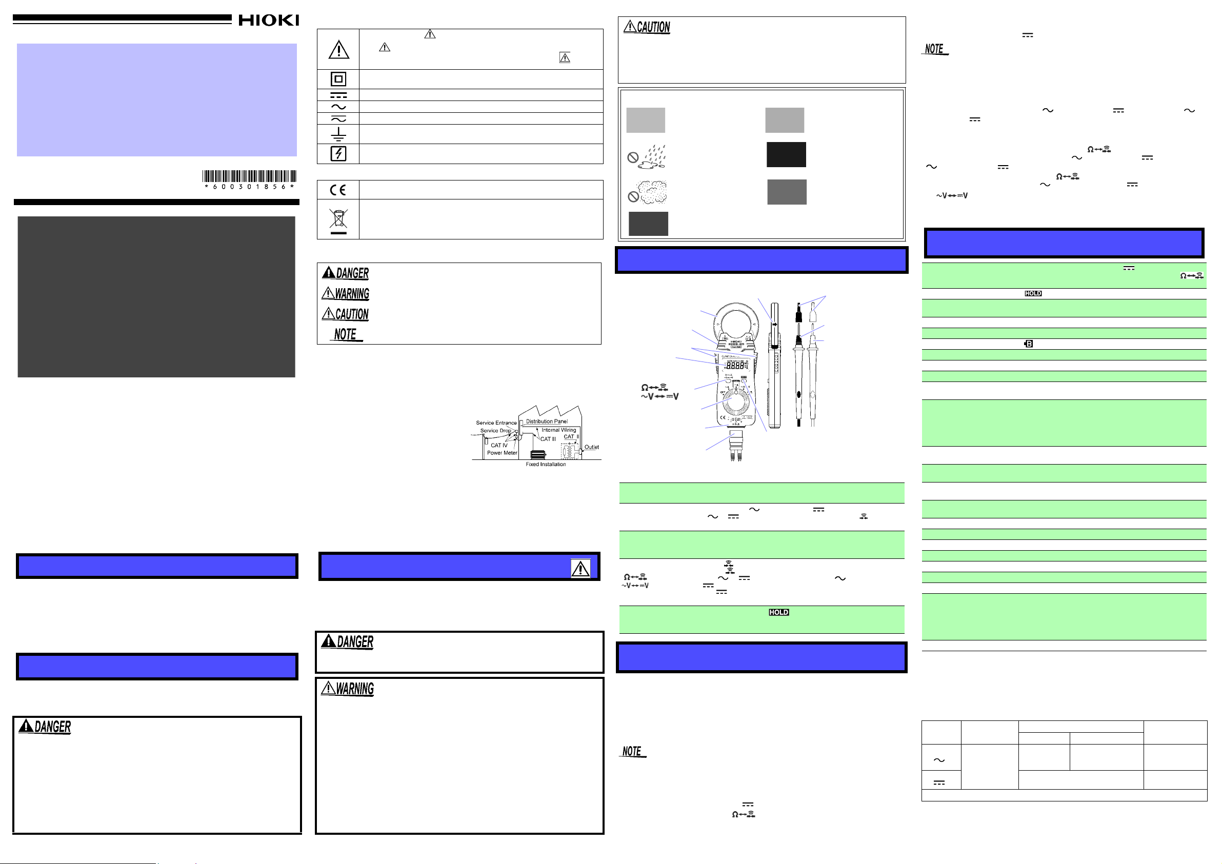
LCD panel
Clamp sensor
Current direction indicator
Operation grip
Function selector
HOLD key
Measurement
Plug
key
*Battery cover (rear side)
Test lead plug
Barrier
key
(Display: Measurement value,
Units, Symbols, Decimal point)
terminal
Red test lead (+)
Black test lead (-)
Sleeves
Warranty malfunctions occurring under conditions of normal use in conformity
with the Instruction Manual and Product Precautionary Markings will be repaired
free of charge. This warranty is valid for a period of three (3) years from the date
of purchase. Please contact the distributor from which you purchased the product for further information on warranty provisions.
Introduction
Thank you for purchasing the HIOKI Model 3288-20 CLAMP ON AC/DC HiTESTER. To obtain maximum performance from the instrument, please read this
manual first, and keep it handy for future reference.
Initial Inspection
When you receive the instrument, inspect it carefully to ensure that no damage
occurred during shipping. If damage is evident, or if it fails to operate according
to the specifications, contact your dealer or Hioki representative.
Overview
The HIOKI Model 3288-20 CLAMP ON AC/ DC HiTESTER is a compact and
lightweight instrument that enables you to measure up to maximum of AC/DC
1000 A. Besides measuring current, the 3288-20 also con tains DMM functions
for AC and DC voltage, resistance and continuity testing. With "True RMS" measurement, it can handle measurement of distorted curren t waveforms. In AC cur rent mode it guarantees accuracy of measurement for frequency from 10 Hz.
I
Safety
This manual contains information and warnings essential for safe operation of
the instrument and for maintaining it in safe operating condition. Before using it,
be sure to carefully read the following safety precautions.
This instrument is designed to comply with IEC 61010 Safety
Standards, and has been thoroughly tested for safety prior to
shipment. However, mishandling during use could result in
injury or death, as well as damage to the instrument. Using th e
instrument in a way not described in this manual may negate
the provided safety features. Be certain that you understand the
instructions and precautions in the manual before use. We disclaim any responsibility for accidents or injuries not resulting
directly from instrument defects.
1234
Safety Symbols
In the manual, the symbol indicates particularly important information
that the user should read before using the instrument.
The symbol printed on the instrument indicates that the user should
refer to a corresponding topic in the manual (marked with the symbol)
before using the relevant function.
Indicates a double-insulated device.
Indicates DC (Direct Current).
Indicates AC (Alternating Current).
Indicates both DC (Direct Current) and AC (Alternating Current).
Indicates a grounding terminal.
Indicates that the instrument may be connected to or disconnected from a
live circuit.
Symbols for Various Standards
This symbol indicates that the product conforms to regulations set out by
the EC Directive.
WEEE marking:
This symbol indicates that the electrical and electronic appliance is put on
the EU market after August 13, 2005, and producers of the Member States
are required to display it on the appliance under Article 11.2 of Directive
2002/96/EC (WEEE).
The following symbols in this manual indicate the relative importance of cautions
and warnings.
Indicates that incorrect operation presents an extreme hazard that
could result in serious injury or death to the user.
Indicates that incorrect operation presents a significant hazard that
could result in serious injury or death to the user.
Indicates that incorrect operation presents a possibility of injury to the
user or damage to the device.
Indicates advisory items related to performance or correct operation of
the instrument.
Measurement categories
This instrument the current measurement section complies with CAT III 600 V safety requirements, and the voltage measurement section complies with CAT III 300
V , CAT II 600 V safety requirements. T o ensure safe operation of measurement instruments, IEC 61010 establishes safety standards for various electrical environments, categorized as CA T
CAT II: Primary electrical circuits in equipment connected to an AC electrical outlet
by a power cord (portable tools, household appliances, etc.) CAT II covers directly measuring electrical outlet receptacles.
CAT III: Primary electrical circuits of heavy
equipment (fixed installations) connected
directly to the distribution panel, and feeders from the distribution panel to outlets.
CAT IV: The circuit from the service drop to the service entrance, and to the
power meter and primary overcurrent protection device (distribution panel).
Using a measurement instrument in an environment designated with a highernumbered category than that for which the instrument is rated could result in a
severe accident, and must be carefully avoided.
Use of a measurement instrument that is not CAT -rated in CA T II to CA T IV measurement applications could result in a severe accident, and must be carefully
avoided.
II
to CAT IV, and called measurement categories.
Usage Notes
Follow these precautions to ensure safe operation and to obtain the full benefits
of the various functions.
Before using the instrument the first time, verify that it operates normally to ensure that no damage occurred during storage or shipping. If you find any damage, contact your dealer or Hioki representative.
To avoid electric shock, do not touch the portion beyond the
protective barrier during use.
• Check that there is no damage to the clamp sensor, instrument case before using. Do not use if there is any damage as
it could lead to electric shock.
• Before using the instrument, make sure that the insulation on
the test leads is undamaged and that no bare conductors are
improperly exposed. Using the instrument in such conditions
could cause an electric shock, so contact your dealer or Hioki
representative for repair.
• During current measurement, to avoid an electric shock accident, do not connect the test leads to the instrument.
• To avoid electric shock when measuring live lines, wear
appropriate protective gear, such as insulated rubber gloves,
boots and a safety helmet.
• Be careful to avoid dropping the instrument or otherwise subjecting them to
mechanical shock, which could damage the mating surfaces of the core and
adversely affect measurement.
• Keep the clamp jaws and core slits free from foreign objects, which could
interfere with clamping action.
Avoid the following locations that could cause an accident or damage to the instrument.
Exposed to direct sunlight
Exposed to high temperature
Exposed to liquids
Exposed to high hu-
midity or condensation
Exposed to high levels
of particulate dust
Subject to vibration
In the presence of corrosive or explosive gases
Exposed to strong electromagnetic fields
Near electromagnetic
radiators
Near induction heating systems. (e.g., high-frequency
induction heating systems
and IH cooking utensils)
Names and Functions of Parts
Operation grip
Function selector
Test lead Plug
key
key
HOLD key
The clamp sensor at the same side as the pushed grip
opens.
OFF, AC current [ A], DC current [ A], AC Voltage/DC Voltage [ V/ V], Resistance and continuity test [/]
(Power is turned on in any position other than OFF.)
Connect the test lead plug to the measurement terminal of the
instrument for voltage measurement, resistance measurement or
continuity testing.
•For [
/ ] function: Resistance measurement [] or Continuity
testing [ ] is switchable.
• For [ V/ V] function: AC voltage [ V] or DC voltage
[ V] is switchable.
• For [ A] function: Pressing this key together with HOLD key
initiates zero adjustment.
When press HOLD key, appears in the display and the digital display value is maintained. Press HOLD key again to cancel
the data HOLD function.
Functions and Display
The display is blanked automatically . (Auto Power Save Function)
• The auto power save function is activated automatically when the power is
turned on. (Not possible to cancel)
• This function automatically switches to the power save state when 10 minutes have elapsed since the last operation. (Power save state)
• To restore from the auto power save state, turn the function selector to the
OFF position once.
The auto power save function cannot be canceled. A minute amount of power continues to flow while in the power save state. If you will not be using the t ester for an
extended period of time, set the function selector to OFF or rem ove t he b atte ry.
Zero-adjust Function
• Before measuring DC current [ A], you must perform zero adjustment by
simultaneously pressing the and
the instrument.
HOLD keys while there is no input to
• The zero adjustment function compensates for sensor magnetization and
changes in current display over time. This function is only effective with measurement of DC current [ A].
Please do not perform zero adjustment while there is any input to the instrument.
Also note that the zero-adjust function will not function when the display count is
greater than 1000.
The measurement range is automatically set to the most appropriate range. (Auto-range Function)
When measuring an AC current [ A], DC current [ A], AC voltage [ V],
DC voltage [ V], or resistance [], the measurement range is automatically
set to the most appropriate range.
A manual range setting becomes available. (Manual Range Function)
Power on the tester while holding down the or HOLD key to select a
manual range for measuring AC current [ A], DC current [ A], AC voltage
[ V], DC voltage [ V] or resistance []. Note that this function is not available for continuity testing. Press the key to step to the next range.
To switch between AC voltage [ V] and DC voltage [ V], press and hold
the key for at least one second.
Indication when the input is out of range. (Overflow indication)
When the input exceeds the measurement range, "O.F" or "-O.F" is displayed.
Specifications
Zero-adjust Function
Data hold indication
Auto power save
LCD panel 4199 maximum display value
Out of range indication O.F or -O.F
Battery low warning
Zero suppression 5 count or less (current measurement only)
Display update rate 400 ms ±25 ms
Range switching Auto range / Manual range
Crest factor
Dielectric strength
Location for use
Maximum conductor diameter
for measurement
Operating temperature and
humidity
Temperature characteristics
Storage temperature
Power supply CR2032 lithium battery x 1 (Rated supply voltage 3 V DC)
Maximum rated power 15 mVA
Continuous operating time Approx. 35 hours (continuous, no load)
Dimensions Approx. 57W x 180H x 16D mm (2.24"W x 7.09"H x 0.63"D)
Mass Approx. 150 g (5.3 oz.)
Accessories Instruction Manual, L9208 Test Leads, 9398 Carrying Case
Maximum rated voltage to earth
Applicable standards Safety : EN 61010, EMC: EN 61326
Accuracy
• Guaranteed accuracy period is 1 year
sor 10,000 times, whichever comes first).
Accuracy guarantee for temperature and humidity:
•
80%RH or less (no condensation)
• Battery warning indicator is not lighting.
AC current measurement: true RMS value, DC current measurement: average value
Function Range
ACA
( A)
DCA
( A)
Effect of conductor position: within ±2.0% (in any direction from sensor center)
100.0 A
1000 A
Before measuring DC current [ A], you must perform
zero adjustment by simultaneously pressing the
and HOLD keys.
Power save state when 10 minutes have elapsed since
the last operation.
“ ” is on, the measurement accuracy cannot be guaranteed.
Current range: 3 max. (1000 A range is 2 max.)
Voltage range: 1.5 max.
4290 V rms sine wave ( for 1 min ) between case and circuit.
7060 V rms sine wave ( for 1 min ) between clamp sensor
and case.
5400 V rms sine wave ( for 1 min ) between clamp sensor
and circuit.
Altitude up to 2000 m (6562 feet), indoors
Pollution Degree 2
35 mm (1.38") or less
0 to 40°C (32 to 104°F), 80%RH max. (no condensation)
In 0 to 40°C range: 0.1 x Measurement accuracy /°C
(In 32°F to 104°F range: 0.56 x Measurement accuracy /°F)
-10 to 50°C (14 to 122°F),
Current measurement (ACA, DCA):
Measurement Category CAT III 600 V
(anticipated transient overvoltage 6000 V)
Voltage measurement (ACV, DCV):
Measurement Category CATIII 300 V, CATII 600 V
(anticipated transient overvoltage 4000 V)
(Opening and closing of the Clamp sen-
Accuracy ±(%rdg.+dgt.)*
45 to 66 Hz
±(1.5%+5) ±(2.0%+5)
DC ±(1.5%+5)
80%RH max.
23±5°C (73°F±9°F) and
10 to 45, 66 to 500 Hz
(no condensation)
Max. input current
1000 A rms AC
continuous
(See
Figure. 1)
1000 A DC
continuous
Page 2
AC voltage measurement: true RMS value, DC voltage measurement: average value
㪇
㪉㪇㪇
㪋㪇㪇
㪍㪇㪇
㪏㪇㪇
㪈㪇㪇㪇
㪈㪉㪇㪇
㪈㪇 㪈㪇㪇 㪈㪇㪇㪇
㪠㫅㫇㫌㫋㩷㪽㫉㪼㫈㫌㪼㫅㪺㫐㪲㪟㫑㪴
㪠㫅㫇㫌㫋㩷㪺㫌㫉㫉㪼㫅㫋㪲㪘㪴
Figure 1. Permissible current to frequency
OK
NO
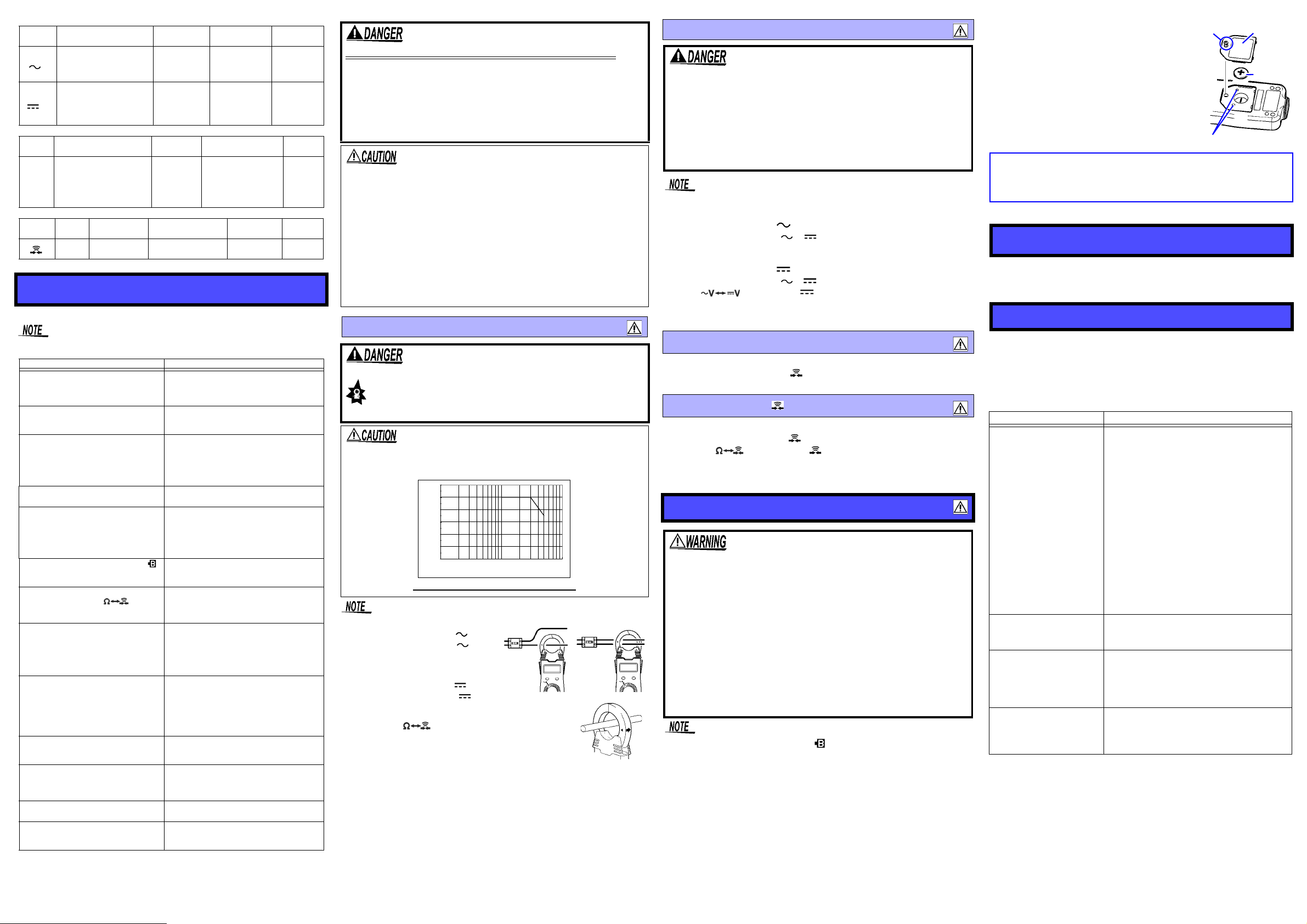
+
-
Battery
cover
Battery
Adjustment screws
Screw
CALIFORNIA, USA ONLY
This product contains a CR Coin Lithium Battery which contains
Perchlorate Material - special handling may apply.
See www.dtsc.ca.gov/hazardouswaste/perchlorate
Function
4.200 V (0.400 to 4.199 V)
42.00 V (4.00 to 41.99 V)
ACV
( V)
( V)
Resistance
Function
Continuity test
Function Range
420.0 V (40.0 to 419.9 V)
600 V (400 to 600 V)
420.0 mV (40.0 to 419.9 mV)
4.200 V (0.400 to 4.199 V)
DCV
42.00 V (4.00 to 41.99 V)
420.0 V (40.0 to 419.9 V)
600 V (400 to 600 V)
measurement
420.0 (40.0 to 419.9 )
4.200 k
42.00 k (4.00 to 41.99 k)
420.0 k
4.200 M
42.00 M(4.00 to 41.99 )
420.0 ±(2.0%+6) Less than 50 ±40 3.4 V or less
Range
(Accuracy range)
Range
(Accuracy range)
(0.400 to 4.199 k)
(40.0 to 419.9 k)
(0.400 to 4.199 )
Accuracy
±(%rdg.+dgt.)*
Accuracy
±(%rdg.+dgt.)*
±(2.3%+8)
30 to 500 Hz
±(1.3%+4)
Accuracy
±(%rdg.+dgt.)*
±(2.0%+4)
±(2.0%+4)
±(2.0%+4)
±(2.0%+4)
±(5.0%+4)
±(10.0%+4)
Threshold level
(beep sound)
Input
impedance
11 M±5%
10 M±5%
10 M±5%
10 M±5%
100 M or more
11 M ±5%
10 M ±5%
10 M ±5%
10 M ±5%
Open terminal
voltage
3.4 V or less
0.7 V (typ.) 3.4 V or less
0.47 V (typ.) 3.4 V or less
0.47 V (typ.) 3.4 V or less
0.47 V (typ.) 3.4 V or less
0.47 V (typ.) 3.4 V or less
Open terminal
voltage
Max. input
voltage
600 V rms AC
600 V DC
protection
* rdg.: reading or displayed value, dgt.: resolution
Measurement Procedures
Check the following before using the instrument.
After turning on the instrument and changing over the functions, it could take a
dozen seconds to stabilize the display.
Check items Diagnose and Solution
Check whether the cladding of the test
lead is not torn and the white or red portion (insulation layer) inside the cable is
not exposed.
Check whether the clamp sensor or the
case is free of damage.
Make sure that the mating portion of the
clamp sensor tip is mate properly.
Make sure there are no missing display
of the LCD panel.
Make sure that the display of the LCD
panel is not dim or faint.
Make sure that the battery indicator " "
does not light up when power is turned
on.
Check whether Zero adjustment can be
made by pressing both key and
HOLD key simultaneously in DC current
measurement mode.
Check whether the reading is around 0 A
when no measurements are being made
in AC current measurement mode.
(Although there is the case that the reading is around 0.1 A, the accuracy of measurement can be guaranteed as it is.)
Check whether the reading is around 0 V
while the test leads are short-circuited in
voltage measurement mode. (Although
there is the case that the reading is
around 0.01 V in AC voltage measurement mode, the accuracy of measurement can be guaranteed as it is.)
Make sure that an abnormal value is not
displayed when a known value is measured in voltage measurement mode.
Check whether the reading is around 0
while the test leads are short-circuited in
resistance measurement mode. (Check
for open circuit in the test leads)
Check whether the "O.F" appear when
moving the test leads apart.
Check whether a beep sound is generated when the test leads are shortcircuited in continuity test mode.
When damage is found, replace with the
specified new test leads Model L9208. Failure to do so may result in electric shock.
If damage is present, avoid using the instrument. Use of the instrument under these conditions may result in electric shock.
If the mating portions do not mate properly,
accurate measurements cannot guaranteed.
Gently wipe off any dirt with a soft cloth found
on the surface of the mating portions. If the
sensors do not mate properly, repair is necessary.
If missing, repair is necessary.
If the display is dim or faint, the environmental condition may be low temperature (lower
than 0°C) or battery may be exhausted. In
case of battery exhaustion, replace battery.
If the display remains dim even after the battery is replaced, repair is necessary.
If the indicator is on, the measurement accuracy cannot be guaranteed. Replace battery
immediately.
If Zero adjustment cannot be made, accurate
measurement is not possible. Repair is necessary.
When some large value is displayed, something is wrong with the instrument. Repair is
necessary.
(See-Troubleshooting)
If the reading is not around 0 V, check
whether the test leads are open circuit or not.
When no open circuit condition is present,
the instrument itself needs repair.
If an abnormal value is displayed, repair is
necessary.
If the reading is not around 0
test leads Model L9208.
If the "O.F" does not appear, repair is necessary.
When the test leads are not open circuited
and no beep sound is generated, repair is
necessary.
, replace the
5 678
Overload
protection
250 V
AC/DC
Overload
250 V
AC/DC
Observe the following precautions to avoid electric shock.
• Always verify the appropriate setting of the function selector
before connecting the test leads. Disconnect the test leads
from the measurement object before switching the function
selector.
• Never apply voltage to the test leads when the Resistance, or
Continuity Test functions are selected. Doing so may damage
the instrument and result in personal injury. To avoid electrical
accidents, remove power from the circuit before measuring.
• Removable sleeves are attached to the metal pins at the ends of the test
leads. To prevent a short circuit accident, be sure to use the test leads with
the sleeves attached when performing measurements in the CAT III measurement category. Remove the sleeves from the test leads when performing measurements in the CAT II measurement categories. For details on
measurement categories, see "Measurement categories" in the instruction
manual.
• When performing measurements with the sleeves attached, be careful to
avoid damaging the sleeves. If the sleeves are inadvertently removed during measurement, be especially careful in handling the test leads to avoid
electric shock.
• The tips of the metal pins are sharp, so take care not to injure yourself.
• Be careful to avoid dropping the instrument or otherwise subjecting them to
mechanical shock, which could damage the mating surfaces of the core
and adversely affect measurement.
Current Measurement
The maximum rated voltage between input terminals and
ground is CAT III 600 V. In current measurement mode,
attempting to measure voltages exceeding CAT III 600 V
with respect to ground could damage the instrument and
result in personal injury.
Do not exceed the maximum input current rating. Doing so may
cause the heat generation of clamp sensors and result in damage to
the instrument or burn injuries.
Attach the clamp around only one conductor.
Measuring AC Current [ A]
1. Set the function selector to A.
Clamp the tester on the conductor, so that
2.
the conductor passes through the center of
the clamp core.
Measuring DC Current [ A]
1. Set the function selector to A.
2. After making sure that there is not input to the instrument, perform zero adjustment by simultaneously
pressing the and HOLD keys.
3. Clamp the line to be measured so that the arrow on the
side of the clamp sensor points in the direction of current flow and the line is position in the center of the
sensor jaws. (A negative reading will result if the arrow
points in the opposite direction.)
Voltage Measurement
• The maximum input voltage is 600 V AC/DC. Attempting to
measure voltage in excess of the maximum input could
destroy the instrument and result in personal injury or death.
• To avoid electrical shock, be careful to avoid shorting live
lines with the test leads.
• In voltage measurement mode, the maximum rated voltage
between input terminals and ground is CATIII 300 V, CAT II 600 V.
In current measurement mode, attempting to measure voltages
exceeding CATIII 300 V, CAT II 600 V with respect to ground
could damage the instrument and result in personal injury.
Make sure that the test lead plug is inserted into the measurement terminal of
the instrument correctly.
Measuring AC Voltage [ V]
1. Set the function selector to V/ V.
2. Connect the test leads to the object to be measured. When measuring AC
voltage, the polarity of the leads can be ignored.
Measuring DC Voltage [ V]
1. Set the function selector to V/ V.
2. Press key to display V.
3. Connect the red (+) lead to the +side of the circuit to be measured and the
black (-) lead to the -side. A negative reading will result if the leads are
reversed.
Resistance Measurement []
Plug the test leads into the measurement terminal.
1. Set the function selector to
/ .
2. Connect the test leads to the object to be measured.
Continuity Test [ ]
Plug the test leads into the measurement terminal.
1. Set the function selector to
/.
2. Press the key, so that the indication appears.
3. Connect the test leads to the object to be measured. Conductivity is good
when the beep sounds.
Replacing Battery
• If the instrument is co nnected to a line that is to be measured,
dangerous voltage levels may be applied to the terminals, and
removing the case may expose live components. To avoid
electric shock when replacing the battery, first disconnect the
instrument and the test leads from the object being measured.
Also, after replacing the battery, always replace the cover and
tighten the screw before using the instrument.
• Use only CR2032 (Panasonic or MAXELL) lithium battery. Use
of any other battery may result in explosion.
• Battery may explode if mistreated. Do not short-circuit,
recharge, disassemble or dispose of in fire.
• Be sure to insert them with the correct polarity. Otherwise,
poor performance or damage from battery leakage could
result. Replace batteries only with the specified type.
• Handle and dispose of batteries in accordance with local regulations.
• Keep batteries away from children to prevent accidental swallowing.
• When the battery is exhausted, the “ ” indication appears in the display.
• The battery included with this instrument was inserted for Testing Purposes
only. Battery life will vary. Please replace the original battery with a new battery as soon as it is depleted.
• CR2032 lithium batteries (Panasonic or MAXELL) can be purchased at electronics and appliance stores where specialized batteries are sold.
• Do not turn the adjustment screws as this may disrupt the measurement values.
• Do not overtighten the screw on the battery cover. Doing so may damage the
main body of the instrument (recommended tightening torque: 0.1 N/m).
1. Remove the instrument and the test leads from the
test item, and power the instrument off.
2. Remove the instrument from the case, and
remove the screws on the battery cover.
3. Remove the used battery.
4. Being careful about the polarity, insert the new
battery of the specified type. (CR2032 lithium
battery: Panasonic or MAXELL)
5. Replace the battery cover and fasten the screws.
Maintenance and Service
To clean the instrument wipe it gently with a soft cloth moistened with water or
mild detergent. Never use solvents such as benzene, alcohol, acetone, ether,
ketones, thinners or gasoline, as they can deform and discolor the case.
Troubleshooting
When the instrument is not functioning properly and if you have not performed
the pre-operation inspection, please do so now. If you cannot find a problem in
the pre-operation inspection, please refer to the following symptoms before contacting your dealer or the nearest Hioki representative. When you send the unit
for repair, please pack the unit carefully so that it will not be damaged during
transport, and write a detailed description of the problem. Hioki cannot bear any
responsibility for damage that occurs during shipment.
Symptom Description
• Waveform containing components out of the
frequency property range cannot be measured accurately.
• In the case that the sample to be measured is
a distorted waveform, the measured value with
the 3288-20 and that with another clamp-on
The measured value of
current or voltage is different
from the measured value
with other clamp-on tester.
The measured current value
is smaller than expected.
The measured current value
is larger than expected.
(current value is displayed
even with no input.)
Roaring sound is heard
around the clamp sensors.
tester using MEAN value method (Average
value rectified, effective value display) are different. Using true RMS method, the 3288-20
can measure such a waveform accurately.
• In the case that the sample to be measured
is the waveform with both AC and DC components, half or full-wave rectified waveform,
accurate measurement is not be possible
due to the large margin of error. We recommend using another instrument with AC+DC
mode.
• The measurement value is not correct, if the
measurement is performed leaving the clamp
jaws open.
• Accurate measurement is not possible in the
presence of strong magnetic fields, such as
transformers and high-current conductors, or
in the presence of strong electromagnetic
fields such as radio transmitters.
When the current of the sample is higher than
500 A or the frequency is higher than 200 Hz,
the roaring sound may be generated from the
clamp sensors.
 Loading...