

Page 1
1. Remove the battery cover, and in its
place fit the test lead holder (option).
Fasten thescrews securely.
2. Insert the test lead probe into the test
lead holder.
1.
2.
HEAD OFFICE
81 Koizumi, Ueda,Nagano 386-1192, Japan
TEL +81-268-28-0562/ FAX +81-268-28-0568
E-mail: os-com@hioki.co.jp
HIOKI USA CORPORATION
6 CorporateDrive, Cranbury, NJ 08512,USA
TEL +1-609-409-9109/ FAX +1-609-409-9108
URL:http://www.hioki.co.jp
3288
CLAMP ON AC/DC HiTESTER
INSTRUCTION MANUAL
June 2001 Revised edition 2 Printed in Japan
3288A980-02 01-06H
Introduction
Inspection
Accuracy
Function Range
Accuracy (%rdg. +dgt.)
Max. allowable
current
45 to 66 Hz 10 to 45, 66 to 500 Hz
ACA
(
A)
100.0 A
1000 A
(1.5% +5) (2.0% +5)
1000 Arms
continuous
DCA
(
A)
100.0 A
1000 A
DC (1.5% +5)
1000 Arms
continuous
Function
Range
(Accuracy range)
Accuracy
(%rdg. +dgt.)
Input impedance
Max.allowable
voltage
ACV
(
V)
4.200 V (0.420to 4.200 V)
42.00 V (4.20to 42.00 V)
420.0 V (42.0to 420.0 V)
600 V (420 to 600 V)
(2.3% +8)
30 to 500Hz
11 MΩ 5%
10 MΩ 5%
10 MΩ 5%
10 MΩ 5%
600 Vrms
DCV
(
V)
420.0 mV (42.0to 420.0 mV)
4.200 V (0.420to 4.200 V)
42.00 V (4.20to 42.00 V)
420.0 V (42.0to 420.0 V)
600 V (420 to 600 V)
(1.3% +4)
100 MΩ or more
11 MΩ 5%
10 MΩ 5%
10 MΩ 5%
10 MΩ 5%
600 V DC
Function
Range
(Accuracy range)
Accuracy
(%rdg. +dgt.)
Open terminal voltage
Overload
protection
Ω
420.0 Ω (42.0to 420.0 Ω)
4.200 kΩ (0.420to 4.200 kΩ)
42.00 kΩ (4.20to 42.00 kΩ)
420.0 kΩ (42.0to 420.0 kΩ)
4.200 MΩ (0.420to 4.200 MΩ)
42.00 MΩ (4.20to 42.00 MΩ)
(2.0% +4)
(2.0% +4)
(2.0% +4)
(2.0% +4)
(5.0% +4)
(10.0% +4)
3.4 V orless
0.7 V (typ.)3.4 V or less
0.47 V (typ.)3.4 V or less
0.47 V (typ.)3.4 V or less
0.47 V (typ.)3.4 V or less
0.47 V (typ.)3.4 V or less
250 Vrms
Function Range
Accuracy
(%rdg. +dgt.)
Buzzer
Open terminal
voltage
Overload
protection
Continuity 420.0 Ω (2.0% +6) 50 Ω 30 Ω 3.4 V orless 250 Vrms
Safety Symbols
This symbol is affixed to locations on the equipment where the operator
should consult corresponding topics in this manual (which are also
marked with the
symbol) before using relevant functions of the
equipment.
In the manual, this symbol indicates explanations which it is particularly
important that the user read before using the equipment.
Indicates a device which is double-insulated.
Indicates DC (Direct Current).
Indicates AC (Alternating Current).
Indicates bothDC (Direct Current) and AC (Alternating Current).
Indicates a grounding terminal.
DANGER
Indicates that incorrect operation presents extreme danger of
accident resulting in death or serious injury to the user.
WARNING
Indicates that incorrect operation presents significantdangerof
accident resulting in death or serious injury to the user.
CAUTION
Indicates that incorrect operation presents possibilityof injuryto
the user or damage to the equipment.
NOTE
Denotes items of advice related to performance of the equipment
or to its correct operation.
Specification
Zero-adjust Function Before measuring DCcurrent ( ), you must perform zeroadjustment by
simultaneously pressingthe (Ω ) andHOLD keys.
LCD panel 4199 maximum display value
Out of rangeindication OF or -OF
Battery low warning
Data hold indication
Zero suppression 5 count orless (current only)
Display update rate 400 ms 25 ms
Range switching Auto range/ Manual range
Withstand voltage 3.7 kV rms sine wave(for 1 minute ) betweencase and circuit
5.55 kV rms sinewave (for 1 minute )between clamp sensor and case
5.55 kV rms sinewave (for 1 minute )between clamp sensor and circuit
Effect of radiated radiofrequency electromagnetic
field(in3V/m)
Current measurement: 40 A within
Location for use Altitude up to 2000m (6562 feet), indoors
Maximum conductor
diameter for measurement
35 mm (1.38")
Operating temperature and
humidity
0to40 (32 to 104 ), 80%rh or less(no condensation)
Storage temperature -10 to 50 (14 to 122 ) (no condensation)
Temperature
characteristics
In 0 to40 range: 0.1 x Measurementaccuracy /
(In 32 to 104 range: 0.56 x Measurementaccuracy / )
Power supply Ratedsupplyvoltage 3 V DC x 1 CR2032 x 1 Lithium battery
Maximum rated power 15 mVA
Continuous operating time 60 hoursor more (continuous, noload)
Dimensions and mass 57(W) x 180(H) x 16(D) mm, approx. 150 g
2.24"(W) x 7.09"(H) x 0.63"(D), approx.5.3 oz.
Accessories Instruction Manual,9398 CARRYING CASE, 9208 TEST LEADS
Options 9209 TEST LEADSHOLDER
Standards accuracy Safety:
EN 61010-1:1993+A2:1995
Current measurement (ACA, DCA) Pollution Degree 2 Overvoltage
Category (CAT) III (anti cipated transient overvoltage 6000 V)
Voltage measurement (ACV, DCV) Pollution Degree 2 Overvoltage
Category (CAT) II (antici patedt ransient overvoltage 4000 V)
EN 61010-2-031:1994,EN 61010-2-032:1995
UL3111-1:1994, UL3111-2-32:1999, CAN/CSA-C22.2No. 1010.1-92+B-97,
CAN/CSA-C22.2No. 1010.2.031-94,CAN/CSA-C22.2No. 1010.2.032-96
EMC:
EN 61326-1:1997+A1:1998
Safety
DANGER
This equipment is designed to comply with IEC 61010-1 Safety Standards,
and has been tested for safety prior to shipment. During high voltage
measurement, incorrect measurement procedures could result in injury or
death, as well as damageto the equipment. Please read this manual
carefully and be sure that you understand its contents before using the
equipment. The manufacturer disclaims all responsibility for any accident or
injury except that resulting due to a defect in its product.
Notes on Operation
DANGER
To avoid short circuits and accidents that could result in injury or death,
use clamp testers only with power lines carrying 600 V AC or less.
The maximum rated working voltage is 600 V AC/DC. Do not measure
voltage in excess of these limitations, as doing so may damage the unit
or cause an accident that might result in injury or death.
Always connect the clamp sensor or test leads to the secondary side of a
breaker. On the secondary side of a breaker, even if the lines are shorted
the breaker can trip and prevent an accident. On the primary side,
however, the current capacity may be large, and in the event of a shortcircuit there may be a serious accident.
WARNING
To prevent electric shock, do not allow the unit to become wet and do
not use the unit when your hands are wet.
To avoid electric shock accidents, when carrying out measurement on
live lines, wear proper protectivegear, including insulating rubber gloves,
insulating rubber boots, and safety helmet, and use extreme caution.
CAUTION
Do not use or store the unit where it is exposed to direct sunlight, high temperatures,
high humidity, or condensation. If exposed to such conditions,theunitmaybe
damaged, the insulation may deteriorate, and the unit may no longer satisfy its
specifications.
Before using the unit, inspect it and checktheoperationto make sure that the unit
was not damaged due to poor storage or transport conditions. If damage is found,
contact your dealer or HIOKI representative.
Before using the unit, make sure thatthesheathingon the leads is not damaged
and that no bare wire is exposed. If thereisdamage, using the unit could cause
electric shock. Replacethe lead with the specified 9208.
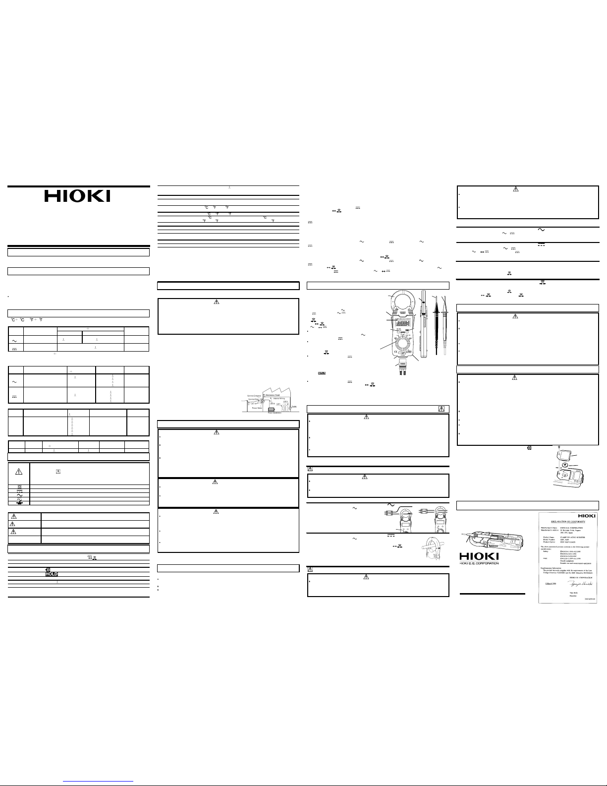
Functions and Display
Names and Functions ofParts
11.
10.
Display:
Measurement
value
Units
Symbols
Decimal
point
1.
5.
6.
7.
Battery cover (rear)
2.
4.
4.
8.
9.
3.
Measurement Procedures
DANGER
Before taking a measurement, check the position of the function switch.
Setting the function incorrectly may damage the unit or cause an accident
that might result in injury or death. When changing the function,
disconnect the test leads from the object to be measured.
Do not input a voltage to the resistance measurement function and the
continuity test function. Doing so may damage the unit or cause an
accident resulting in injury or death.
At the time as the continuity test, to avoid electrical accidents, turn off
the power before measuring a circuit.
Current Measurement
WARNING
The maximum permissible input is 1000 A. Current measurements
exceeding 1000 A should be of short duration.
During current measurement, to avoid an electric shock accident, do not
connect the test leads to the unit.
MeasuringAC Current
(A)
NoOK
2.
1.
MeasuringDC Current
(A)
+
-
Voltage Measurement
DANGER
The maximum overvoltage protection input is 600 V A C/DC. When
measuring CATIII lines, 300 V rms.
Do not measure voltage in excess of these limitations, as doing so may
damage the unit or cause an accident that might result in injury or death.
DANGER
If the end of a test lead short-circuits lines with a voltage between them,
this is very dangerous and can lead to a serious accident. Exercise great
care when measuring voltages.
The maximum rated voltage to ground is 600 V AC/DC.
Do not attempt to measure voltages exceeding 600 V with respect to
ground. This could result in injury or damage to the unit.
MeasuringAC Voltage
(V)
MeasuringDC Voltage
(V)
Resistance Measurement ( Ω )
Continuity Test ( )
Maintenance
CAUTION
If the protective functions of the unit are damaged, either remove the unit from
service or post warnings to prevent others from using the unit inadvertently.
Gently wipe dirt from the surface of the unit with a soft cloth moistened with a small
amount of water or mild detergent. Do not tryto clean the unit usingcleaners
containing organic solvents such as benzine, alcohol, acetone, ether, ketones,
thinners, or gasoline. They may cause discoloration or damage.
When not in use fora long time,topreventpossiblecorrosion caused by battery
leakage, remove the battery before storage.
If the unit is not functioning properly, check the battery and test leads. If a problem is
found, contact your dealer or HIOKI representative. Pack the unit carefullyso that it
will not be damaged during transport, and write a detailed description of the problem.
HIOKI cannot bear any responsibility for damage that occurs during shipment.
Replacing Battery
WARNING
If the unit is connected to a line that is to be measured, dangerous
voltage levels may be applied to the terminals, and removing the case
may expose live components.
To avoid electric shock when replacing the battery, first disconnect the
unit and the test leads from the object being measured. Also, after
replacing the battery, always replace the cover and tighten the screw
before using the unit.
Use only CR2032 lithium battery. Use of any other battery may result in
explosion.
When replacing the battery, be sure to insert it with the polarity correct.
Battery may explode if mistreated. Do not short-circuit, recharge,
disassemble or dispose of in fire.
Keep used batteries out of the reach of children. Dispose of used
batteries according to their type in the prescribed mannerand in the
proper location.
Battery cover
Battery
Using the 9209 Test Lead Holder (Option)
Thank you for purchasing this HIOKI 3288 CLAMP ON AC/DC HiTESTER.
To get the maximum performance from the unit, please read this manual first, and keep
it at hand.
When the unit is delivered, check that it hasnotbeen damagedintransit. If the unit is
damaged, or fails to operate according to the specifications,contact yourdealerorHIOKI
representative.
If reshipping the unit, preferably use the original packing.
Before Use
Before using the unit, inspect it and check the operation to make sure that the
sheathing on the leads is not damaged and that no bare wire is exposed.
If there is damage, using the unit could cause electric shock. Contact your dealer or
HIOKI representative.
23
5 (73 9 ) 80% rh or less, no condensation
AC current measurement: mean value, DC current measurement:averagevalue
Effect of conductor position:
2.0% (in any direction from sensor center)
Voltage in measured circuit: max. 600 V AC rms (insulated conductor)
AC voltage measurement: mean value, DC voltage measurement:average value
Resistance
Continuity
The followingsymbols are used in thisInstruction Manual to indicate therelative importance of cautions
and warnings.
In order to ensure safe operation and to obtain maximum performance from the unit,
observe the cautions listed below.
Overvoltage Categories
To ensure safe use of measurement, IEC 60664 establishes safety level
standards for different locations, classified as CAT I through CAT IV, and
called overvoltage categories. These are defined as follows.
CAT I: Secondary electrical circuits that are connected to a wall outlet
through a transformer or similar device.
CAT II: Primary electrical circuits in equipment connected to a wall outlet via
a power cord (portable tools, household appliances, etc.)
CAT III: Primary electrical circuits of heavy equipment (fixed installations)
connected directly to the distribution panel, and feeders between the
distribution panel and outlets.
CAT IV: The circuit from the service drop to the service entrance, then to the
power meter and to the primary overcurrent protection device.
Higher-numbered categories correspond to
electrical environments with greater
momentary energy, so a measurement
device designed for CAT III environments
can endure greater momentary energy than
a device designed for CAT II. Use of a
lower category product in a higher category
environment could result in a severe accident and must be carefully avoided.
NOTE
: Accurate measurement may be impossible in locationssubject to strong external
magnetic fields, such as transformersand high-currentconductors, or in locations subject
to strong external electric fields, such as radio transmission equipment.
Auto Power Save Function
This function automatically switches to the power save state when 10 minutes have
elapsed since the last operation.
The auto power save function is activated automatically when the power is turned on.
To restore from the auto power save state, turn the function switch to the OFF position
once.
NOTE
: The auto power save function cannot be canceled.
A minute amount of power continues to flow while in the power save state. If you will not
be using the tester for an extended period of time, set the function switch to OFF or
remove the battery.
Zero-adjust Function
Before measuring DC current ( ), you must perform zero adjustm entbysimultaneously
pressing the (Ω ) and HOLD keys while there is no input to the unit.
The zero adjustment function compensates for sensor magnetization and changes in
current display over time. This function is only effective with measurementof DC current
(
).
NOTE:
Please do not perform zero adjustment while there is any input to the unit. Also
note that the zero-adjust function will not function when the display count is greater than
1000.
Auto-range Function
When measuring anAC current ( A), DC current ( A), AC voltage ( V), DC voltage
( V), or resistance (Ω), the measurement range is automatically set to the most
appropriate range.
Manual Range Function
Power on the tester while holding down the Ω keyor HOLD keyto selectamanual
range for measuring AC current ( A), DC current ( A), AC voltage ( V), DC voltage
(
V) or resistance (Ω). Note that this function is not available for continuity testing.
Press the Ω key to step to thenextrange. To switch between AC voltage ( V)
and DC voltage (
V), press and hold the V V key for at least one second.
Overflow indication
When the input exceeds the measurement range, "OF" or "-OF" is displayed.
1. Display
2. Clamp sensor
3. Current direction indicator
4. Operation grip
5. Function switch
OFF / AC current (
A) / DC current
(
A) / Voltage ( / V) /
Resistance and Continuity check (Ω/
)
6. Ω
key
V Vkey
Measuring voltage
Switches between AC voltage ( V)
and DC voltage (
V)
Measuring resistance or continuity
Switches between resistance
measurement (Ω) and continuity
testing (
).
Measuring DC current ( A)
Pressing this key together with
HOLD key initiates zero adjustment.
7. HOLD key
Press this to hold the display value
(the
indication appears). Press
once more to cancel the hold function.
Measuring DC current ( A)
Pressing this key together with Ω key initiates zero adjustment.
8. Connector 9.Plug
Connect the test lead plug to the connector for voltage measurement, resistance
measurement, or continuity testing. Align the slot on the plug with the key in the
connector.
10. Red test lead (+) 11. Black test lead (-)
NOTE
: The frequency of a distorted waveform, such as on the secondary side of an
inverter, may not be indicated correctly.
NOTE
: Clamp the tester on one lead only.
1. Set the function switch to
A.
2. Clamp the tester on the conductor, so that
the conductor passes through the center of
the clamp core.
1. Set the function switch to
A.
2. After making sure that there is not input to the unit, perform
zero adjustment by simultaneously pressing the (Ω ) and
HOLD keys.
3. Clamp the line to be measured so that the arrow on the side of
the clamp sensor points in the direction of current flow and the
line is position in the center of the sensor jaws. (A negative
reading will result if the arrow points in the opposite direction.)
Check that the test lead plug is firmly connected to the tester before beginning
measurement.
1. Set the function switch to
V/ V.
2. Connect the test leads to the object to be measured. When measuring AC voltage,the
polarity of the leads can be ignored.
1. Set the function switch to
V/ V.
2. Press V V key to display .
3. Connect the red (+) lead to the + side of the circuit to be measured and the black (-)
lead to the - side. A negative reading will result if the leads are reversed.
Plug the test leads into the connector.
1. Set the function switch to Ω /
.
2. Connect the test leads to the object to be measured.
Plug the test leads into the connector.
1. Set the function switch to Ω /
.
2. Press the Ω key,so thatthe indication appears.
3. Connect the test leads to the object to be measured. Conductivity is good when the
buzzer sounds.
NOTE
: When the batteryis exhausted, the indication
appears in the display.
1. Remove the unit and the test leads from the test item,
and power the unit off.
2. Remove the unit from the case, and remove the screws
on the batterycover.
3. Remove the used battery.
4. Being careful about the polarity, insert the new battery of
the specified type. (CR2032 lithium battery)
5. Replace the battery cover and fasten the screws.
NOTE
: The battery included with this unit was inserted for
TESTING PURPOSES ONLY. Battery life will vary. Please
replace the original battery with a new CR2032 lithium battery as soon as it is depleted.
CR2032 lithium batteries can be purchased at electronics and appliance stores where
specialized batteries are sold.
 Loading...