

Page 1

POWER HiTESTER
CLAMP ON
INSTRUCTION MANUAL
3286
Page 2

Contents
Introduction i
Shipping Check
ii
Safety
iii
Attentions During Use
vii
Organization of This Manual
xii
Chapter 1 Product Outline
1
1.1 Product Outline 1
1.2 Features
2
1.3 Parts and Functions
3
1.4 Flowchart of Key Operations
9
1.4.1 Current Measurements Mode 9
1.4.2 Harmonic Measurement
11
1.4.3 Change the Range
11
Chapter 2 Measurement Procedure 13
2.1 Preparations 13
2.2 Connections
14
2.3 Range Setup
20
2.4 Power Measurement
21
2.4.1 1φφφφ P Meter, 1φφφφ PF Meter and 3φφφφ PF Meter 22
2.4.2 Power and Power Factor
25
2.4.3 Phase Detection
27
2.4.4 Current
28
2.4.5 Voltage
29
2.5 Harmonic Measurement 30
2.5.1 Current Harmonics 30
2.5.2 Voltage Harmonics
32
2.6 Data Hold Function HOLD 33
Page 3
2.7 SLOW Mode 33
2.8 Recording Function
REC
33
2.9 SETUP Function
35
2.10 Measurement Condition Save Function
36
2.11 Auto Power-Off Function
APS 37
2.12 Battery Low Warning
37
2.13 Beep Tone
37
2.14 DATA OUTPUT
38
Chapter 3 Specifications 39
3.1 Measurement Specifications
(23
5 , 80% RH max.) 39
3.1.1 AC Current Measurement Specifications 39
3.1.2 AC Voltage Measurement Specifications
40
3.1.3 Specifications of Single-phase Power
Measurement 1φφφφ PMeter
41
3.1.4 Specifications of Power Factor
and Phase Angle Measurements
1φφφφ PF Meter and 3φφφφ PF Meter
42
3.1.5 Specifications of Balanced Three-phase
Power Measurements
43
3.1.6 Specifications of Frequency Measurement
44
3.1.7 Specifications of Harmonic Measurement
44
3.2 General Specifications 45
3.3 Operation Expressions
48
Chapter 4 Battery Replacement 51
Chapter 5 Attaching The Hand Strap
53
Chapter 6 Troubleshooting
55
Chapter 7 Service
57
Page 4

i
Introduction
Introduction
Thank you for purchasing this HIOKI "3286
CLAMP ON POWER HiTESTER." To get the
maximum performance from the product, please read
this manual first, a nd keep this at hand.
Importance
This product is the clamp on power meter which
keeps measurement function of the multiple
functions. If you set up a function mode in
advance, the mode will start up from the next use.
Have it set up for the preferable use. (Refer to "2.10
Measurement Condition Save Function)
Request
We have tried to bring this manual as close to
perfection as we could achieve. If perchance you
find any unclear portions, mistakes, omissions, or
the like, we would be most obliged if you could
please notify us of them via any HIOKI agent, or
directly.
Page 5

ii
Shipping Check
Shipping Check
When you receive the product, inspect it carefully to
ensure that no damage occurred during shipping. In
particular, check the accessories, panel switches, a nd
connectors.
If damage is evident, or if it fails to operate
according to the specifications, contact your dealer
or HIOKI representative.
Check the 3286 Unit and the Supplied
Accessories
Main unit
3286 CLAMP ON POWER HiTESTER
Supplied accessories
9355 Carrying Case 1
9635 Voltage cord 1
Hand Strap 1
Battery 6LF22 alkaline battery 1
Instruction manual 1
Options
9636 RS-232C CABLE
9636-01 RS-232C PACKAGE
9442 PRINTER (DPU-414, Seiko Instrument Inc.)
Page 6

iii
Safety
DANGER
This equipment is designed according to IEC
61010 Safety Standards, and has been tested for
safety prior to shipment. Incorrect measurement
procedures could result in injury or death, as
well as damage to the equipment. Please read
this manual carefully and be sure that you
understand its contents before using the
equipment. The manufacturer disclaims all
responsibility for any accident or injury except
that resulting due to defect in its product.
Safety
This manual contains information and warnings
essential for safe operation of the product and for
maintaining it in safe operating condition. Before
using the product, be sure to carefully read the
following safety notes.
Page 7
iv
Safety
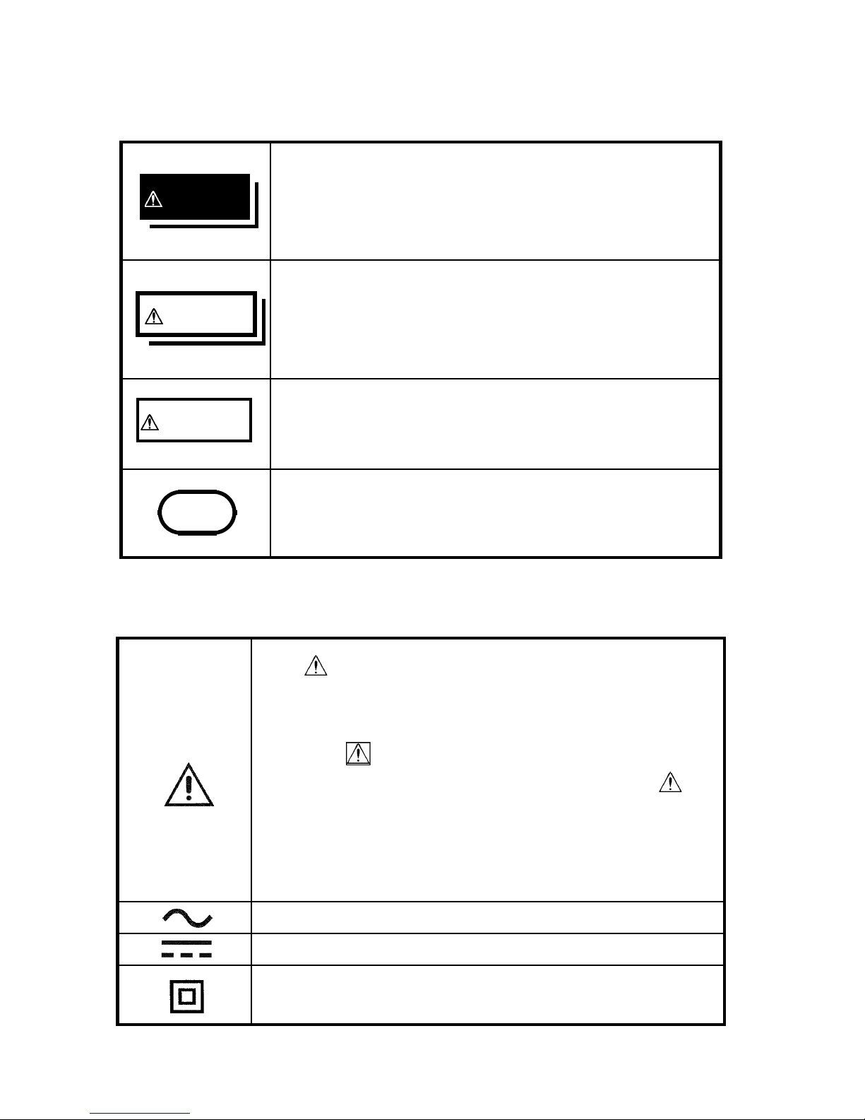
DANGER
Indicates that incorrect operation
presents extreme danger of accident
resulting in death or serious injury to the
user.
WARNING
Indicates that incorrect operation
presents significant danger of accident
resulting in death or serious injury to the
user.
CAUTION
Indicates that incorrect operation
presents possibility of injury to the user
or damage to the equipment.
NOTE
Denotes items of advice related to
performance of the equipment or to its
correct operation.
The symbol printed on the product
indicates that the user should refer to a
corresponding topic in the manual (marked
with the symbol) before using the
relevant function. In the manual, the
symbol indicates particularly important
information that the user should read
before using the product.
Indicates AC (Alternating Current).
Indicates DC (Direct Current).
Indicates a device which is double-
insulated.
The following symbols in this manual indicate the
relative importance of cautions and warnings.
Safety Symbols
Page 8

v
Safety
We define measurement tolerances in terms of rdg.
(reading) and dgt. (digit) values, with the following
meanings:
rdg. (reading or displayed value)
The value currently being measured and indicated
on the measuring product.
dgt. (resolution)
The smallest displayable unit on a digital measuring
product, i.e., the input value that causes the digital
display to show a "1".
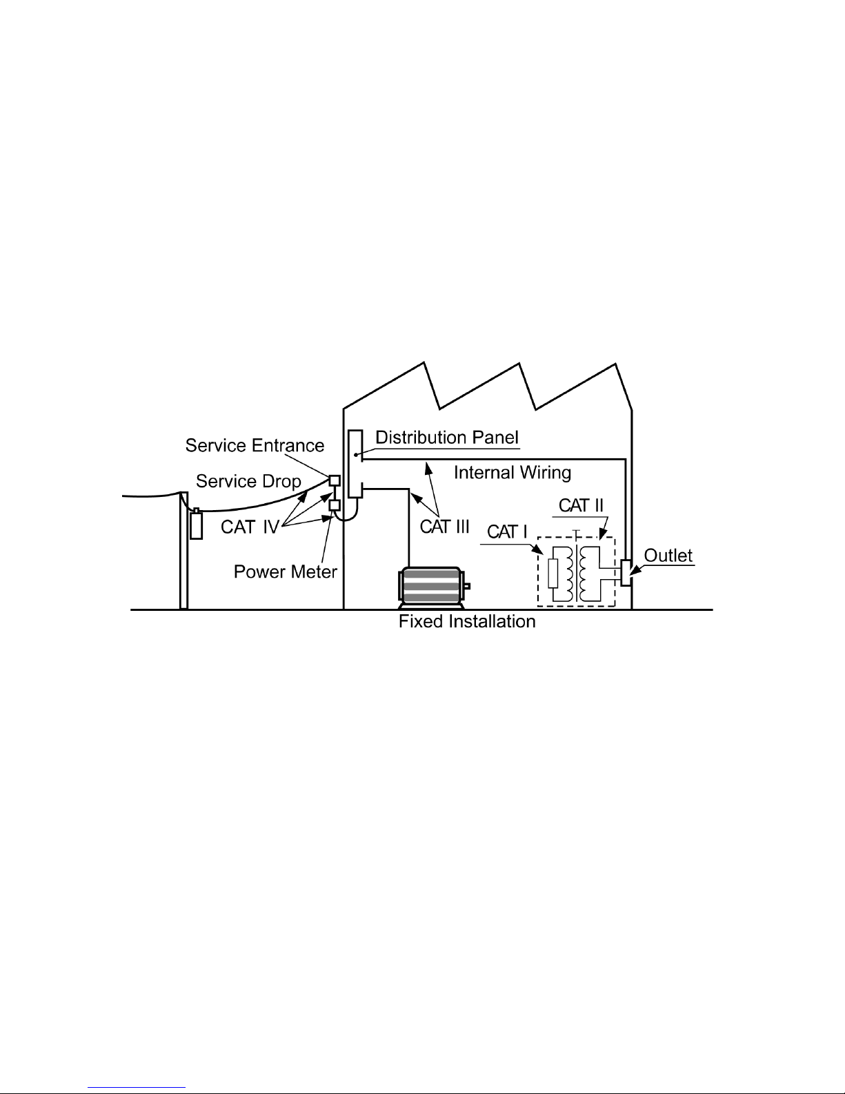
Overvoltage Categories
To ensure safe use of measurement, IEC 60664
establishes safety level standards for different
locations, classified as CAT I through CAT IV, and
called overvoltage categories. These are defined as
follows.
CAT I: Secondary electrical circuits that are
connected to a wall outlet through a
transformer or similar device.
CAT II: Primary electrical circuits in equipment
connected to a wall outlet via a power
cord (portable tools, household appliances,
etc.)
CAT III: Primary electrical circuits of heavy
equipment (fixed installations) connected
directly to the distribution panel, and
feeders between the distribution panel and
outlets.
CAT IV: The circuit from the service drop to the
service entrance, then to the power meter
and to the primary overcurrent protection
device.
Page 9
vi
Safety
Higher-numbered categories correspond to electrical
environments with greater momentary energy, so a
measurement device designed for CAT III
environments can endure greater momentary energy
than a device designed for CAT II. Use of a lower
category product in a higher category environment
could result in a severe accident and must be
carefully avoided.
Page 10
vii
Attentions During Use
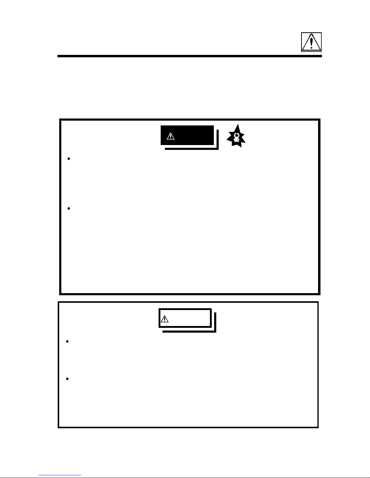
DANGER
To avoid short circuits and potentially lifethreatening hazards, never attach the clamp to a
circuit that operates at more than the maximum
rated voltage / 600V, or over bare conductors.
Clamp-on probe should only be connected to
the secondary side of a breaker, so the breaker
can prevent an accident if a short circuit occurs.
Connections should never be made to the
primary side of a breaker, because unrestricted
current flow could cause a serious accident if a
short circuit occurs.
WARNING
To avoid electric shock, do not allow the
product to get wet, and do not use it when your
hands are wet.
To avoid electric shock when measuring live
lines, wear appropriate protective gear, such as
insulated rubber gloves, boots and a safety
helmet.
Attentions During Use
Follow these precautions to ensure safe operation
and to obtain the full benefits of the various
functions.
Page 11
viii
Attentions During Use
WARNING
The clamp sensor and voltage cord should be
connected to live lines after being connected to
the unit. To prevent short-circuiting and electric
shock, observe the following precautions:
Do not short-circuit the two wires of a line with
the clip of the voltage cord. Do not use the
clamp sensor on bare conductors.
To avoid electric shock when replacing the
battery, first disconnect the voltage cable or
clamp from the object to be measured. After
replacing the battery, always replace the cover
and tighten the screw before using the unit.
When replacing the battery, be sure to insert
them with the correct polarity. Otherwise, poor
performance or damage from battery leakage
could result. Replace battery only with the
specified type.
To avoid the possibility of explosion, do not
short circuit, disassemble or incinerate
batteries.
Handle and dispose of batteries in accordance
with local regulations.
Page 12
ix
Attentions During Use
CAUTION
Avoid stepping on or pinching the cable, which
could damage the cable insulation.
Keep the cables well away from heat sources, as
bare conductors could be exposed if the insulation
melts.
If the protective functions of the product are
damaged, either remove it from service or mark it
clearly so that others do not use it inadvertently.
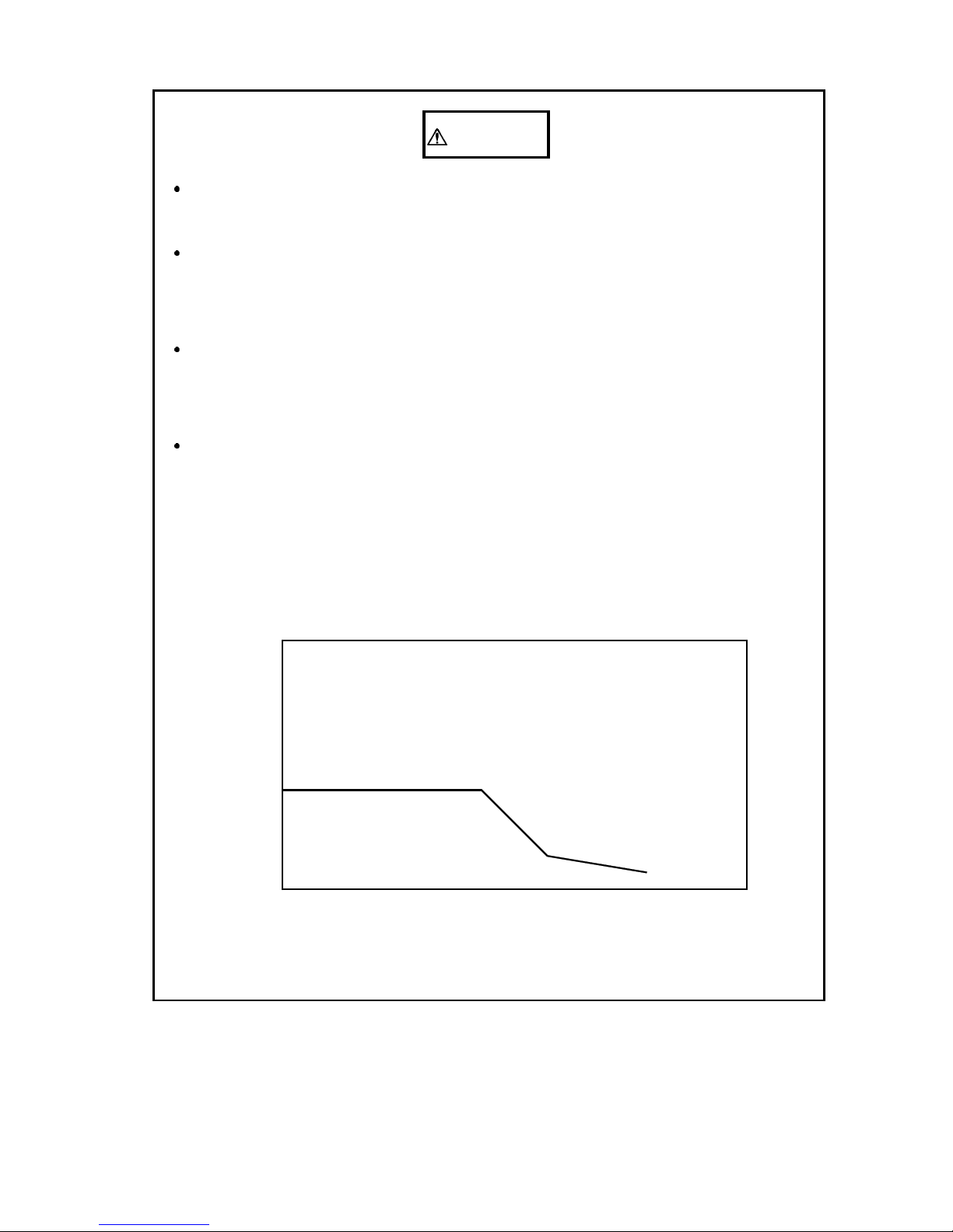
Do not exceed the maximum input current rating,
which depends on the frequency of the current
being measured. Be careful about the evolution of
heat, when the input frequency is high.
2500
2000
1500
1000
500
0
10 100 1k 10k 100k
Frequency [Hz]
Current
(ACA)
Page 13
x
Attentions During Use
CAUTION
Do not store or use the product where it could be
exposed to direct sunlight, high temperature or
humidity, or condensation. Under such conditions,
the product may be damaged and insulation may
deteriorate so that it no longer meets specifications.
The product is a precision instrument: do not clamp
any foreign objects in the end of the clamp core, or
insert anything in the core gap.
To avoid damage to the product, protect it from
vibration or shock during transport and handling,
and be especially careful to avoid dropping. Do not
exert excessive pressure on the clamp sensor or
attempt to wedge the sensor into a tight spot for
measurement.
Measurements are degraded by dirt on the mating
surfaces of the clamp-on sensor, so keep the
surfaces clean by gently wiping with a soft cloth.
Before using the product the first time, verify that it
operates normally to ensure that the no damage
occurred during storage or shipping. If you find any
damage, contact your dealer or HIOKI
representative.
This product is designed for indoor use, and
operates reliably from 0
to 40 .
This product is not designed to be entirely water- or
dust-proof. To avoid damage, do not use it in a
wet or dusty environment.
Adjustments and repairs should be made only by
technically qualified personnel.
Page 14
xi
Attentions During Use
CAUTION
Do not use the product if the battery is exhausted
(when the
mark lights in the display area). Be sure
to replace the exhausted battery with a new one.
When replacing the battery, make sure that the
metal battery snap fitting is firmly connected. If the
metal fitting is loose, adjust it and recheck the
connection.
To avoid corrosion from battery leakage, remove the
batteries from the product if it is to be stored for a
long time.
NOTE
Before using the product, make sure that the
insulation on the voltage cable and probes is
undamaged and that no bare conductors are
improperly exposed. Using the product in such
conditions could cause an electric shock. Replace
the test leads and probes with the specified HIOKI
Model 9635.
Accurate measurement may be impossible in the
presence of strong magnetic fields, such as near
transformers and high-current conductors, or in the
presence of strong electromagnetic fields such as
near radio transmitters.
To clean the product, wipe it gently with a soft
cloth moistened with water or mild detergent.
Never use solvents such as benzene, alcohol,
acetone, ether, ketones, thinners or gasoline, as they
can deform and discolor the case.
Page 15

xii
Organization of This Manual
Organization of This Manual
Chapter 1
Product Outline
Explains the parts and functions of the unit.
Chapter 2
Measurement Procedure
Explains how to use the 3286 for measurement.
Chapter 3
Specifications
Lists the specifications of the 3286 CLAMP ON
AC/DC HiTESTER.
Chapter 4
Battery Replacement
Explains how to replace the battery used to power
the 3286.
Chapter 5
Attaching the Hand Strap
Explains how to attach the hand strap, for easy
handling of the unit in the field.
Chapter 6
Troubleshooting
Describes how to check before requesting service.
Chapter 7
Service
Explains how to get the unit serviced.
Page 16

1
Chapter 1 Product Outline
Chapter 1
Product Outline
1.1 Product Outline
The "3286 CLAMP ON POWER HiTESTER" is
designed to provide multiple functions by adopting
a single-chip microcomputer. At any desired point
of a single-phase circuit or three-phase circuit, this
unit enables the measurement of voltage, current,
power, power factor, phase angle, reactive power or
frequency, and the detection of phase sequence on
live lines.
When this unit is connected to the 9442 printer
(DPU-414, Seiko Instrument Inc.) by a 9636 RS232C cable (both purchased separately), the
products DATA OUTPUT function can be used to
output data to the printer.
Page 17

2
Chapter 1 Product Outline
1.2 Features
A multi-function microcomputer
The built-in microcomputer offers various functions
in a compact form.
Display of true rms values
The true rms value conversion circuit allows
accurate measurement of currents with distorted
waveforms.
Enables power measurement
When both current and voltage are input
simultaneously, the power factor, phase angle,
reactive factor, as well as power can be measured,
and phase detected.
Enables harmonic measurement
Higher harmonics of current and voltage up to the
20th order can be measured. Moreover, overall
harmonic distortion factors and content can be
displayed.
DATA OUTPUT function
Data can be output when the unit is directly
connected to a printer. This function requires the
optional 9442 printer (DPU-414, Seiko Instrument
Inc.) and 9636 RS-232C cable.
Page 18
3
Chapter 1 Product Outline
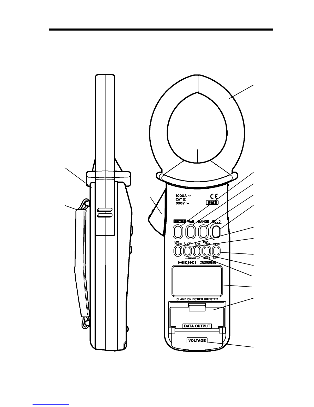
Top and Side View
1
2
3
4
5
6
9
8
13
14
10
11
15
16
12
7
17
1.3 Parts and Functions
Page 19
4
Chapter 1 Product Outline
1.
POWER
Used to turn power on/off
2.
Watt
key
Used to select the display of active power, apparent
power, or power factor for the 1φ P meter.
Used to select the display of power factor, phase
difference, or reactive factor for the 1φ PF meter.
Used to select the display of active power, apparent
power, power factor, phase difference, or reactive
factor for the 3φ PF meter.
3.
RANGE
key
Displays the current and voltage ranges, and enables
the setting of these ranges. (The
U/
and
I/
keys are used to set these ranges.)
4.
HOLD
key
Holds the indicated value.
Used for the measurement condition save function.
Holding down the
HOLD
key when powering off:
The measurement conditions are saved to the
internal memory when powering off. The
measurement conditions are automatically restored
when powering on.
Holding down the
HOLD
key when powering on:
Measurement conditions are reset to the initial
values.
5.
LINE/HARM
key
Cycles through single-phase power measurement,
three-phase power measurement, current harmonic
measurement, and voltage harmonic measurement.
Page 20
5
Chapter 1 Product Outline
6.
U/
(RANGE) key
Selects voltage display mode. Pressing this key in
voltage display mode resets the peak-hold value.
Switches MAX/MIN display of effective value and
peak value during REC.
Enables the setting of a voltage range in range setup
mode.
Lowers the order in harmonic display mode.
7.
I/
(RANGE) key
Selects current display mode. Pressing this key in
current display mode resets the peak-hold value.
Switches MAX/MIN display of effective value and
peak value during REC.
Enables the setting of a current range in range setup
mode.
Raises the order in harmonic display mode.
8.
MAX/MIN
(SET2) key
Switches the REC function on and off.
9.
MODE
(SET1) key
Pressing this key in power display mode switches
between current/voltage display and reactive power
display.
Pressing this key during harmonic measurement
switches between overall harmonic distortion factor
display (THD-R, THD-F) and harmonic content
display.
Pressing this key during REC lets you to check the
elapsed time and remaining battery capacity.
Used to start SETUP. (The unit is powered on with
the
SET1
key held down.)
Page 21

6
Chapter 1 Product Outline
10. Clamp sensor
To measure current, open the top ends of the clamp
sensor by gripping the lever 11. Then position the
conductor to be measured at the center of the clamp
sensor and firmly close the clamp sensor.
11. Lever
Used to open and close the clamp sensor.
12. Current direction mark
When measuring power, clamp the conductor with
the arrow facing the load side.
13. Data Output terminal
Connected to the optional 9636 RS-232C cable to
provide output.
14. Voltage measurement terminal
Connected to the 9635 test lead (red and black,
supplied with the unit) to measure voltage and
harmonic.
15. Back case
To replace the battery, remove the two screws.
16. Hand strap
Attach to get a better grip on the unit.
Page 22

7
Chapter 1 Product Outline
Display 1
Display 2 Display 3
17. Display (LCD)
Alternating Current (AC)
cosφφφφ Power factor
sinφφφφ Reactive factor
HOLD
Data hold function
DATA
Data output
RST Three-Phase
Reverse phase
Normal phase
Missing phase
APS
Auto power off function
S Slow
REC Record function
LEAD Lead phase
LAG Lag phase
Battery low warning
Phase angle (deg.)
A Current
PEAK Wave peak value
Page 23

8
Chapter 1 Product Outline
W Active power
VA Apparent power
V Voltage
MAX Maximum value
MIN Minimum value
% Harmonic percentage
%THD Total harmonic distortion ratio
Hz Frequency
var (reactive power)
Total harmonic distortion ratio-F
(A distortion rate against the basic wave.)
Total harmonic distortion ratio-R
(A distortion rate toward the actual
effective value.)
Page 24

9
Chapter 1 Product Outline
LINE/HARM key
Watt key
COSφ
U, I
P
U, I
S
U, I
1φ Pmeter
SINφ
U, I
COSφ
U, I
φ
U, I
1φ PF meter
COSφ
U, I
P
U, I
S
U, I
3φ PF meter
SINφ
U, I
φ
U, I
MODE key
(P,S only)
P
U, I
P
vAr, Q
S
U, I
S
vAr, Q
I/ key
I
Ipeak, IHz
(Return to the power indication
w
ith the Watt key)
U/ key
U
Upeak, UHz
MAX/MIN key
REC ON REC OFF
A point of view: This shows the way of changing on Display 1 to 3.
Display 1
Display 2, Display 3
1φ P
or
1φ PF
3φ
PF
1φ
HARM I
1φ
HARM U
(Return to the power indication
w
ith the Watt key)
1.4 Flowchart of Key Operations
1.4.1 Current Measurements Mode
Page 25

10
Chapter 1 Product Outline
REC ON
Watt key
MODE key
I/
key
U/
key
P
MAX, MIN
S
MAX, MIN
I
MAX, MIN
Ipeak
MAX, MIN
U
MAX, MIN
Upeak
MAX, MIN
(Return to the
power
indication with
the Watt key)
MAX/MIN
display
Elapsed time
display
Remaining
battery
capacity display
(Return to the
power
indication with
the Watt key)
Page 26

11
Chapter 1 Product Outline
LINE/HARM key
MODE key
I/
key
U/
key
1φ P
or
1φ PF
3φ
PF
1φ
HARM I
1φ
HARM U
THD-R
THD-F Content
1st order 2nd-order ---- 20thorder
20th order 19th-order ---- 1storder
Measurement
value indication
RANGE key
RANGE indication
I/ key
U/
key
RANGE
indication
AUTOrange 150Vrange 300Vrange 600Vrange
AUTOrange 200Arange 1000Arange
1.4.2 Harmonic Measurement
1.4.3 ChangetheRange
Page 27

12
Chapter 1 Product Outline
Page 28

13
Chapter 2 Measurement Procedure
Fresh battery
Battery capacity 50%
Battery capacity 0
Beep tone sounds 3 times
Chapter 2
Measurement
Procedure
2.1 Preparations
1. Remove the rear cover and insert a battery. (Refer to
"Chapter4 Battery Replacement".)
2. Press
POWER
to turn the unit on. Verify that all
segments of the display light up briefly. The model
name then appears on Display 1 and battery state on
Display 3.
3. The measuring state of the 1φ P meter or 1φ PF
meter is activated. (The unit was shipped from the
factory with the 1φ P meter selected. For details,
see 2.9, "SETUP Function.")
[Low battery voltage detection function]
After the
mark lights and battery voltage drops
below a certain level, the power goes off
automatically. When this occurs, " "is
displayed.
When power goes off after display of these marks,
replace the exhausted battery with a new one.
Page 29

14
Chapter 2 Measurement Procedure
WARNING
Due to the risk of electric shock, connect the
yellow cord not used for measurement to the
part to which the black cord connects to prevent
the clip from accidentally touching anyone.
NOTE
2.2 Connections
[To initialize the saved contents]
Holding down the
RANGE
key when powering on
initializes all the saved contents. (SETUP Function,
measurement condition save Function)
Before conducting measurement, check the
connections.
Be sure to connect the power clip to the part
bearing the exposure voltage.
Page 30

15
Chapter 2 Measurement Procedure
Red
Yellow
Black
Load
Power supply side
Figure 1.
Power Measurement on Sin
g
le-Phase Two-Wire Circuit
[Single-Phase Two-Wire Circuit]
Page 31

16
Chapter 2 Measurement Procedure
1
N
2
Power supply side
Load
Red
Yellow
Black
Red
Black
Yellow
Figure 2. Power and power factor Measurement
on Sin
g
le-Phase Three-Wire Circuit
[Single-Phase Three-Wire Circuit]
The power and power factor of a single-phase threewire circuit are measured similar to measurement on
a single-phase two-wire circuit. Connect the black
cord to the neutral wire as shown in Figure 2, then
switch the red cord and clamp sensor to the
respective wires. In this way, the power and power
factor between the wires can be measured.
Page 32

17
Chapter 2 Measurement Procedure
1
2
3
Power supply side
Load
Red
Yellow
Black
Figure 3. Power and power factor measurement
on Three-Phase Three-Wire Circuit
1
2
3
1φP, P
1
1φP, P
2
Power supply side
Load
Red
Yellow
Black
Red
Black
Yellow
Three-phase effective power P=P1+P
2
Figure 4. Another method of the power measurement
on Three-Phase Three-Wire Circuit
[Three-Phase Four-Wire Circuit]
Use another method of the power measurement of
the figure 4 for the distortion wave.
Page 33

18
Chapter 2 Measurement Procedure
1
N
2
3
Red
Yellow
Black
Red
Yellow
Black
Yellow
Black
Red
Power supply side
Load
Figure 5. Power and power factor measurement
on Three-Phase Four-Wire Circuit
[Three-Phase Four-Wire Circuit]
The power and power factor of a three-phase fourwire circuit are measured similar to measurement on
a three-phase three-wire circuit (provided the load is
balanced). No neutral wire is used for this
measurement, however.
In case of unbalanced load, measurement is
conducted similar to measurement on a single-phase
two-wire circuit. Set the unit in single-phase
measurement mode.
Connect the black cord to the neutral wire as shown
in Figure 5, then switch the red cord and clamp
sensor to the respective wires. In this way, the
power and power factor between the wires can be
measured.
(To use the phase sequence detection function,
connect the voltage cords to the three wires,
excluding the neutral wire, for measurement.)
Page 34

19
Chapter 2 Measurement Procedure
Power supply side
Load
Figure 6. Current measurement
Red
Yellow
Black
Load
Power supply side
Figure 7. Voltage measurement
[Current measurement]
When only measuring current, the orientation of the
clamp sensor is irrelevant. Moreover, the voltage
cord need not be connected to the unit.
[Voltage measurement]
When only measuring voltage, the clamp sensor
need not be clamped.
Page 35

20
Chapter 2 Measurement Procedure
I/ key
U/
key
AUTOrange 150Vrange 300Vrange 600Vrange
AUTOrange 200Arange 1000Arange
Table 1.
Range Composition for Single-Phase Power Measurement
U Voltage range
I 150.0V 300.0V 600V
Current
range
200.0A 30.00k 60.00k 120.0k
1000A 150.0k 300.0k 600.0k
Unit [W] or [VA] or [var]
2.3 Range Setup
1. Press the
RANGE
key. The voltage range then
appears on Display 2 and current range on Display
3. In this condition, Display 2 and Display 3
should be blinking.
2. To change the voltage range, press the
U/
key.
To change the current range, press the
I/
key.
The power range varies with the combination of
voltage and current ranges as listed in Tables 1 an d
2.
Page 36

21
Chapter 2 Measurement Procedure
Table 2.
Range Composition for Three-Phase Power Measurement
U Voltage range
I 150.0V 300.0V 600V
Current
range
200.0A 60.00k 60.00k
120.0k
240.0k
1000A 300.0k 600.0k 600.0k
1200k
Unit [W] or [VA] or [var]
NOTE
2.4 Power Measurement
3. After changing the range, press the
RANGE
key.
Display 2 and Display 3 then restore the measured
values.
Accurate measurement may be impossible i n
locations subject to strong external magnetic fields,
such as transformers and high-current conductors, or
in locations subject to strong external electric fields,
such as radio transmission equipment.
Make sure that only one conductor is clamped in
the center of the clamp sensor. If you clamp singlephase (2-wire) or three-phase (3-wire) lines together,
it will be impossible to measure.
Page 37

22
Chapter 2 Measurement Procedure
U
I
φ
t
2.4.1 1
φφφφ
P Meter, 1
φφφφ
PF Meter and 3
φφφφ
PF Meter
[1φ PMeter]
Displays active power P once about every second
(once about every three seconds in SLOW mode).
The meter calculates apparent power S, reactive
power Q, and power factor COS φ from active
power P, voltage U, and current I. (See 3.3,
"Operation Expressions.")
[1φ PF Meter and 3φ PF Meter]
The phase angle is measured at the zero-cross point
of voltage U and current I as shown below. The
meter calculates three-phase active power P, threephase apparent power S, three-phase reactive power
Q, and reactive factor SIN φ, and power factor COS
φ from the phase angle φ, voltage U, and current I.
(See 3.3, "Operation Expressions.")
For an inverter or thyristor with distorted input
waveforms, or waveforms with noise superimposed,
the meters may not display accurate values or even
be able to measure at all.
Three-phase active power P is calculated on the 3φ
PF meter under balanced load conditi ons. Accurate
measurements cannot be conducted under an
unbalanced load.
Page 38

23
Chapter 2 Measurement Procedure
Sample Measurements
I U 1φ P Meter λ 1φ PF Meter λ
1.000 1.000
*
0.847 0.750
* Distorted waveforms with crest factor of 1.9.
[Difference in λ between 1φ P Meter and 1φ PF Meter]
For distorted waveforms, the value of power factor λ
may differ between the 1φ P meter and 1φ PF meter.
The difference is due to the fact that the 1φ P
meter calculates λ from active power and apparent
power, while the 1φ PF meter assumes a sine wave
and calculates λ from the phase angles of the
voltage waveform and current waveform of that sine
wave. Therefore, phase-angle measurement serves
as the basis for the 1φ PF meter. Distorted
waveforms and those with noise superimposed may
prevent the meter from measuring power factors
accurately or even at all. Therefore, use λ of the 1φ
P meter for distorted waveforms.
Power factor λ of the 3φ PF meter is also obtained
from the phase angles of voltage waveform and
current waveform of an assumed sine wave.
Therefore, accurate measurements may also not be
conducted with distorted waveforms or those with
noise superimposed. The following example shows
the measurement of power factor λ from power
values on a three-phase ci rcuit.
Page 39

24
Chapter 2 Measurement Procedure
1
(R)
2
(S)
3
(T)
1φP, P
1
1φP, P
2
Three-phase effective power P=P1+P
2
Power supply side
Load
Red
Yellow
Black
Red
Black
Yellow
Measurement example
P(1φ P) S(1φ P)
R -0. 54 k W 2.61 kVA
T 1.98 kW 2.57 kVA
Three-phase effective power
P=P1+P2=-0.54+1.98=1.44 kW
Three-phase apparent power
S=(
)/2 (2.61+2.57)=4.49 kVA
Power factor
λ=P/S=1.44/4.49=0.321
Page 40

25
Chapter 2 Measurement Procedure
Table 3. Items Displayed (Marked OK) and Not Displayed (-)
1φ P 1φ PF 3φ PF
Current I OK OK OK
Voltage U OK OK OK
Effective power P OK - OK
Apparent power S OK - OK
Reactive power Q OK - OK
Power factor λ (COSφ) OK OK OK
Phase angle φ - OK OK
Reactive factor SINφ - OK OK
WARNING
Due to the risk of electric shock, connect the
yellow cord not used for measurement to the
part to which the black cord connects to prevent
the clip from accidentally touching anyone.
1φ P
or
1φ PF
3φ
PF
1φ
HARM I
1φ
HARM U
2.4.2 Power and Power Factor
1. Press the
LINE/HARM
key to select the 1φ P meter,
1φ PF meter, or 3φ PF meter (RST goes on). (For
switching between the 1φ P meter and 1φ PF meter,
see 2.9, "SETUP Function.")
Page 41

26
Chapter 2 Measurement Procedure
COSφ
U, I
P
U, I
S
U, I
1φ P
SINφ
U, I
COSφ
U, I
φ
U, I
1φ PF
COSφ
U, I
P
U, I
S
U, I
3φ PF
SINφ
U, I
φ
U, I
2. Connect the voltage cord to the unit, then connect
the red cord, black cord, and yellow cord to the
circuit under measurement according to prescribed
connections. For a three-phase circuit, the unit will
display the results of phase detection as follows:
Normal phase
Reverse phase
Missing phase
3. Open the tip of the clamp core and clamp the
conductor (on the side to which the red voltage cord
is connected) roughly into the center of the clamp
core, then conduct measurement. In this operation,
clamp the conductor in such an orientation that the
arrow mark on the clamp sensor surface points to
the load side from the power supply side.
4. Select active power, apparent power, power factor,
phase angle, or reactive factor with the
Watt
key.
Note that the 1φ P meter does not display phase
angle and reactive factor. The 1φ PF meter does not
display active power and apparent power.
Page 42

27
Chapter 2 Measurement Procedure
P
U, I
P
vAr, Q
S
U, I
S
vAr, Q
NOTE
NOTE
2.4.3 Phase Detection
5. Pressing the
MODE
key in active power or
apparent power display mode indicates reactive
power. Pressing the
MODE
key again restores the
current and voltage display.
6. Switch between Auto Range and Manual Range, as
needed. For details, see 2.3, "Range Setup."
The 3φ PF meter calculates P, Q and S under a
balanced load.
The 3φ PF meter c annot provide accurate
measurement results under an unbalanced load.
For a missing phase, the unit will not display any
measured value. ("----" will be displayed.)
If the arrow mark on the surface of the clamp
sensor points to the power supply side from the load
side, the phase will be shifted by 180 degrees, thus
disabling measurement. ("----" will be displayed.)
Press the
LINE/HARM
key to select the 3φ PF
meter (RST goes on). Before starting measurement,
check the connections. (See 2.2, "Connections.")
In a three-phase measurement, the unit will display
phase detection results as follows:
Normal phase
Reverse phase
Missing phase
If a load is connected to the electrical line while a
phase is missing on the power supply side, voltage
coming back from the load to the tester may cause
normal or reverse phase to be displayed even though
a phase is missing.
Page 43

28
Chapter 2 Measurement Procedure
NOTE
2.4.4 Current
1. Press the
I/
key to activate current display mode.
In current display mode, the unit will indicate an
effective value on Display 1, peak hold value on
Display 2, and frequency on Display 3.
2. Switch between Auto Range and Manual Range, as
needed. For details, see 2.3, "Range Setup."
3. Open the tip of the clamp core and clamp the
conductor roughly into the center of the clamp core.
4. Pressing the
I/
key in current display mode resets
the peak hold value.
Be sure to clamp one conductor only. Measurement
is not possible for single phase or three phases when
two or three conductors are respectively clamped at
the same time.
When only measuring current, there is no need to
connect the voltage cord.
Select the 1φ P meter, 1φ PF meter, or 3φ PF meter.
The unit does not display polarities in a peak
measurement.
The peak hold value will not vary, unless a large
value is entered in the unit. If the auto power-off
function is effective, the unit will be shut down in
about ten minutes, causing the data to be lost. (See
2.11, "Auto Power-Off Function.") One way to
prevent data from being lost is to disable the auto
power-off function (see 2.9, "SETUP Function") or
to use the recording function.
For measurement extending the auto power-off time,
use the recording function.
To check variations in a peak value, enable the
REC function by pressing the
MAX/MIN
key, then
activate peak value display mode by pressing the
I/
key.
Page 44

29
Chapter 2 Measurement Procedure
NOTE
NOTE
2.4.5 Voltage
Automatic frequency detection (AUTO), 50 Hz
fixed, or 60 Hz fixed can be selected. In cases
where the input fluctuates significantly, the
indicated value will stabilize when 50 Hz or 60 Hz
fixed is selected. For how to select, see the setup of
measurement line frequency in SETUP mode. (For
details, see 2.9, "SETUP Function.")
There is a possibility to fluctuate 2 or 20 counts at
the peak value display when the input becomes big.
1. Press the
U/
key to activate voltage display
mode. In voltage display mode, an effective value
appears on Display 1, peak-hold value on Display 2,
and frequency on Display 3.
2. Connect the voltage cord to the unit, then connect
the red cord, yellow cord, and black cord to the
circuit under measurement.
3. Switch between Auto Range and Manual Range, as
needed. For details, see 2.3, "Range Setup."
4. Pressing the
U/
key in voltage display mode
resets the peak-hold value.
Select the 1φ P meter, 1φ PF meter, or 3φ PF meter.
The unit does not display polarities in a peak
measurement.
The peak hold value will not vary, unless a large
value is entered in the unit. If the auto power-off
function is effective, the unit will be shut down in
about ten minutes, causing the data to be lost.
(See 2.11, "Auto Power-Off Function.") One way to
prevent data from being lost is to disable the auto
power-off function (see 2.9, "SETUP Function") or
to use the recording function.
Page 45

30
Chapter 2 Measurement Procedure
NOTE
1φ P
or
1φ PF
3φ
PF
1φ
HARM I
1φ
HARM U
I/
key
U/
key
1st order 2nd order ---- 20thorder
20th order 19th order ---- 1storder
2.5 Harmonic Measurement
2.5.1 Current Harmonics
For measurement extending the auto power-off time,
use the recording function.
To check variations in a peak value, enable the
REC function by pressing the
MAX/MIN
key, then
activate peak value display mode by pressing the
I/
key.
Automatic frequency detection (AUTO), 50 Hz
fixed, or 60 Hz fixed can be selected. In cases
where the input fluctuates significantly, the
indicated value will stabilize when 50 Hz or 60 Hz
fixed is selected. For how to select, see the setup of
measurement line frequency in SETUP mode. (For
details, see 2.9, "SETUP Function.")
There is a possibility to fluctuate 2 or 20 counts at
the peak value display when the input becomes big.
1. Press the
LINE/HARM
key to activate harmonic
current display mode.
2. Switch between Auto Range and Manual Range, as
needed. For details, see 2.3, "Range Setup."
3. Open the tip of the clamp core and clamp the
conductor roughly into the center of the clamp core.
4. Press the
I/
and
U/
keys to select the order of
harmonics to be measured.
Page 46

31
Chapter 2 Measurement Procedure
MODE
key
THD-R
THD-F Content
NOTE
5. Switch between the total harmonic distortion ratio
(THD-R, THD-F) and harmonic percentage from
one to another, as needed, by pressing the
MODE
key.
Be sure to clamp one conductor only. Measurement
is not possible for single phase or three phases when
two or three conductors are respectively clamped at
the same time.
Automatic frequency detection (AUTO), 50 Hz
fixed, or 60 Hz fixed can be selected. In cases
where the input fluctuates significantly, the
indicated value will stabilize when 50 Hz or 60 Hz
fixed is selected. For how to select, see the setup of
measurement line frequency in SETUP mode. (For
details, see 2.9, "SETUP Function.")
For automatic frequency detection, the unit
performs FFT operations only when the fundamental
wave is covered within the 45 to 65 Hz range. The
unit does not perform FFT operations outside this
range.
Page 47

32
Chapter 2 Measurement Procedure
1φ P
or
1φ PF
3φ
PF
1φ
HARM I
1φ
HARM U
I/
key
U/
key
1st order 2nd order ---- 20thorder
20th order 19th order ---- 1storder
MODE
key
THD-R
THD-F Content
NOTE
2.5.2 Voltage Harmonics
1. Press the
LINE/HARM
key to activate harmonic
voltage display mode.
2. Connect the voltage cord to the unit, then connect
the red cord a nd black cord to the circuit under
measurement.
3. Switch between Auto Range and Manual Range, as
needed. For details, see 2.3, "Range Setup."
4. Press the
I/
and
U/
keys to select the order of
harmonics to be measured.
5. Switch between the total harmonic distortion ratio
(THD-R, THD-F) and harmonic percentage, as
needed, by pressing the
MODE
key.
Automatic frequency detection (AUTO), 50 Hz
fixed, or 60 Hz fixed can be selected. In cases
where the input fluctuates significantly, the
indicated value will stabilize when 50 Hz or 60 Hz
fixed is selected. For how to select, see the setup of
measurement line frequency in SETUP mode. (For
details, see 2.9, "SETUP Function.")
For automatic frequency detection, the unit
performs FFT operations only when the fundamental
wave is covered within the 45 to 65 Hz range. The
unit does not perform FFT operations outside this
range.
Page 48

33
Chapter 2 Measurement Procedure
NOTE
2.6 Data Hold Function HOLD
2.7 SLOW Mode
2.8 Recording Function REC
This function freezes the counter at any desired
point for easy reading.
Press the
HOLD
key.
HOLD
annunciator lights on
the display and the digital display value is
maintained.
The data hold function is available for all
measurements.
To cancel the data hold function, press the
HOLD
key again.
If an indicated value fluctuates rapidly and is
difficult to read, you can select a slower display
update rate (about once every three seconds) to
make it easier to read the indicated value. Set
SLOW display by setting DISP in SETUP mode.
(See 2.9, "SETUP Function.")
SLOW mode is not available for harmonic
measurements.
The recording function can be used to display the
maximum value, the minimum value or the present
measured value.
1. REC annu nciator will blink when you press the
MAX/MIN
key during a current or a voltage
measurement. This function will have stored the
measured data in the internal memory since the key
is pressed.
2. The auto power-off function is automatically
disabled. (
APS
annunciator is tu ned off.)
Page 49

34
Chapter 2 Measurement Procedure
MAX/MIN
display
Elapsed time
display
Remaining
battery
capacity display
NOTE
Items Displayed (Marked OK) and Not Displayed (-)
1φ P 1φ PF 3φ PF
Current I OK OK OK
Current peak value
Ipeak
OK OK OK
Voltage U OK OK OK
Voltage peak value
Upeak
OK OK OK
Effective power P OK - OK
Apparent power S OK - OK
3. Pressing the
MODE
key while using the recording
function lets you check the elapsed time and
remaining battery capacity.
In elapsed time display, the unit indicates hours on
Display 2 and minutes on Display 3.
When elapsed time is displayed with MAX or MIN
blinking, a negative value is denoted.
4. The
HOLD
key will suspend the recording
function.
HOLD
annunciator lights and REC
annunciator stops blinking.
While
HOLD
is shown, the elapsed time is not
increasing. By pressing the
HOLD
key once more,
HOLD
annunciator is off and the recording function
resumes.
5. To reset the recording data during the recording
function, press the
MAX/MIN
key.
When starting the recording function (REC)inan
auto range, the range is set as the recording function
is activated.
Page 50

35
Chapter 2 Measurement Procedure
Display 1
Item No.
Display 2
Item Name
Display 3
Setting
Initial
Value
2.9 SETUP Function
The settings for this unit are made in SETUP mode.
In SETUP mode, you can make settings for
measurements, display, and ancillary functions.
1. Hold down the
SET1
keywhilepoweringonthe
unit by pressing the
POWER
key. This activates
SETUP mode.
2. Select a setting item. The
MODE
key increments
the item No.; the
MAX/MIN
key decrements the
item No.
3. The settings can be modified using the
U/
key or
I/
key.
4. Pressing the
HOLD
key twice in succession restores
the initial values for the setting items.
5. At unit power-off, " " (SAVE END)
appears and the settings are saved.
6. Details of Settings
(1) Setup of single-phase power meter system
Item No. 1-01
ON Sets 1φ PF meter.
OFF Sets 1φ P meter.
Page 51

36
Chapter 2 Measurement Procedure
2.10 Measurement Condition Save
Function
(2) Setup of measurement line frequency
Item No. 1-02
AUTO Automatically detects measurement line
frequency.
50 Hz Sets measurement line frequency to 50 Hz.
60 Hz Sets measurement line frequency to 60 Hz.
(3) Setup of display update rate
Item No. 1-03 (SAMP)
NORM Sets display update to normal rate (1 s).
(NORMAL)
SLOW Sets display update to SLOW (3 s).
(SLOW)
(4) Setup of auto power-off function
Item No. 1-04
ON Enables the auto power-off function.
OFF Disables the auto power-off function.
(5) Setup of buzzer function
Item No. 1-05
ON Enables the buzzer function.
OFF Disables the buzzer function.
1. Hold down the
HOLD
key at unit power-off. The
measurement conditions in effect at that point are
saved.
2. The measurement conditions thus saved are the
measurement line, power, harmonic display, current,
and voltage ranges.
Page 52

37
Chapter 2 Measurement Procedure
2.11 Auto Power-Off Function APS
2.12 Battery Low Warning
2.13 Beep Tone
3. To return the saved measurement conditions to their
initial values, hold down the
HOLD
key at unit
power-on. After the entire LCD goes on, the unit
will display "
", and the saved contents of
measurement conditions are returned to their initial
values.
When
APS
annunciator is displayed, the auto poweroff function is active.
If no key is pressed for about 10 minutes, the u nit
turns itself off automatically.
Immedi ately before turning off automatically,
APS
annunciator blinks and a beep tone is heard for
about 30 seconds.
By pressing any key except
POWER
,youwill
extend the powered state for another 10 minutes.
To enable or disable the auto power-off function, set
APS in SETUP mode. (See 2.9, "SETUP Function.")
Auto Power-Off function becomes ineffective while
a REC function is used.
When this annunciato r lights, the battery is
exhausted and a correct measurement is not assured.
Replace a new battery.
When the battery voltage drops below a certain
level, the unit indicates "
" and is shut
down.
To enable or disable the audible buzzer when
pressing a key, set BEEP in SETUP mode. (See 2.9,
"SETUP Function.")
Page 53

38
Chapter 2 Measurement Procedure
2.14 DATA OUTPUT
The 3286 is connected to the printer or the PC by
using optional 9636 or 9636-01 respectively. See
the instruction manual of the 9636 or the 9636-01
for the setup.
Page 54

39
Chapter 3 Specifications
Maximum permissible
current
1000 Arms continuous
Effect of conductor
position
within 0.7% (in any position from
sensor center)
External magnetic field
interference
AC 400 A/m (external magnetic fields)
corresponds to 2.0 A or less (display)
Voltage in measured
circuit
max. 600 Vrms AC (insulated
conductor)
Range
(Accuracy Range)
Resolution
Accuracy
45Hz to 66Hz
30Hz to 45Hz,
66Hz to 1kHz
200.0A
(10.0rmsA to 200.0rmsA)
0.1A 1.3%rdg. 3dgt. 2.0%rdg. 5dgt.
1000A
(100rmsA to 1000rmsA)
1A 1.3%rdg. 3dgt. 2.0%rdg. 5dgt.
Chapter 3
Specifications
3.1 Measurement Specifications
(23 5 , 80% RH max.)
3.1.1 AC Current Measurement Specifications
AC current (true rms) I
RMS
Page 55

40
Chapter 3 Specifications
Range
(Accuracy Range)
Resolution
Accuracy
30Hz to 1kHz
200A
(10.0Arms to 200.0Arms)
1A 3.0%rdg. 5dgt.
1000A
(100Arms to 1000Arms)
1A 3.0%rdg. 5dgt.
Range
(Accuracy Range)
Resolution
Accuracy
45Hz to 66Hz
30Hz to 45Hz,
66Hz to 1kHz
150.0V
(10.0rmsV to 150.0rmsV)
0.1V 1.0%rdg. 3dgt. 1.5%rdg. 5dgt.
300.0V
(30.0rmsV to 300.0rmsV)
0.1V 1.0%rdg. 3dgt. 1.5%rdg. 5dgt.
600V
(60rmsV to 600rmsV)
1V 1.0%rdg. 3dgt. 1.5%rdg. 5dgt.
Range
(Accuracy Range)
Resolution
Accuracy
30Hz to 1kHz
150V
(10.0Vrms to 150.0Vrms)
1V 3.0%rdg. 5dgt.
300V
(30.0Vrms to 300.0Vrms)
1V 3.0%rdg. 5dgt.
600V
(60Vrms to 600Vrms)
1V 3.0%rdg. 5dgt.
3.1.2 AC Voltage Measurement Specifications
AC current (wave peak value) I
PEAK
AC voltage (true rms) U
RMS
AC voltage (wave peak value) U
PEAK
Page 56

41
Chapter 3 Specifications
Measurement
condition
Single phase, 50/60 Hz
Measurement range Effective measurement current range:
10 A to 1000 A
Effective measurement voltage range:
80 V to 600 V
Out of range If either the current (line current) range
or voltage (line voltage) range is out of
range, power measurement will also be
out of range.
Active power
measurement
Current Current Range
Voltage
200.0A 1000A
Voltage
Range
150.0V 30.00kW 150.0kW
300.0V 60.00kW 300.0kW
600V 120.0kW 600.0kW
Measurement
accuracy
2.3%rdg. 5dgt. (cosφ=1)
Apparent power S, reactive power measurement Q,
power factor COSφ
Method of
measurement
Measurement
accuracy
Measurement range
Obtained by calculation from active
power, current, and voltage
measurements.
1 dgt. with respect to calculation from
each measured value.
[W] in the above table is replaced by
[VA] or [var].
3.1.3 Specifications of Single-phase Power
Measurement 1
φφφφ
P Meter
Page 57

42
Chapter 3 Specifications
Measurement
conditions
Singe phase/balanced three phases,
50/60 Hz, sine wave
Measurement range Effective measurement current range:
10 A to 1000 A
Effective measurement voltage range:
80 V to 600 V
Phase angle measurement φ
Method of
measurement
Measurement range
Obtained from phase detection circuit.
Measurement
Mode
Resolution Measurement Range Accuracy
φ
0.1 LEAD 90 to 0 to LAG 90 3
Power factor measurement λ
Method of
measurement
Measurement range
Obtained by calculation from phase
angles.
Measurement
Mode
Resolution Measurement Range Accuracy*
cosφ 0.001 LEAD 0 to 1 to LAG 0 3 2dgt.
* Calculating error of 2 dgt. is added to phase angle measurement error.
Reactive factor measurement
Method of
measurement
Measurement range
Obtained by calculation from phase
angles.
Measurement
Mode
Resolution Measurement Range Accuracy*
sinφ 0.001 LEAD 0 to 1 to LAG 0 3 2dgt.
* Calculating error of 2 dgt. is added to phase angle measurement error.
3.1.4 Specifications of Power Factor and Phase
Angle Measurements 1φφφφ PF Meter and 3φφφφ
PF Meter
Page 58

43
Chapter 3 Specifications
Active and apparent power measurements
Measurement
conditions
Balanced three phases, 50/60 Hz, sine
wave
Method of
measurement
Active power calculated from apparent
power and phase angle information.
Measurement range (Active power P/Apparent power S)
Current Current (Line Current) Range
Voltage
200.0A 1000A
Voltage
(Line
Voltage)
Range
150.0V 60.00kW 300.0kW
300.0V
60.00kW
120.0kW
600.0kW
600V 240.0kW
600.0kW
1200kw
For apparent power, [W] is replaced by [VA].
Measurement
accuracy
3.0%rdg. 10dgt. (cosφ=1)
Reactive power measurement Q
Method of
measurement
Measurement
accuracy
Measurement range
Obtained by calculation from active and
apparent powers.
1 dgt. with respect to calculation from
each measured value.
The unit of [W] in the above table is
3.1.5 Specifications of Balanced Three-phase
Power Measurements
Page 59

44
Chapter 3 Specifications
Measurement ranges
(For current measurement/voltage measurement)
Range
(Accuracy Range)
Resolution Accuracy
100.0Hz
(30.0Hz to 100.0Hz)
0.1Hz 0.3%rdg. 1dgt.
1000Hz
(100Hz to 1000Hz)
1Hz 1.0%rdg. 1dgt.
Minimum input Current: 10.0 Arms, Voltage: 10.0 Vrms
Measurement
condition
Fundamental wave frequency: 50/60 Hz
Measurement function AC current/AC voltage
Harmonic analysis
Window width
Type of window
Number of analysis
data
Order of analysis
1 cycle (50/60 Hz)
Rectangular
256 points
1st order to 20th order
Analysis item
Harmonic level
Harmonic
percentage
Total harmonic
distortion ratio
Harmonic levels of current and voltage
Harmonic percentage of current and
voltage
Total harmonic distortion ratio of current
and voltage (THD-F and THD-R)
3.1.6 Specifications of FrequencyMeasurement
3.1.7 Specifications of Harmonic Measurement
Page 60

45
Chapter 3 Specifications
Measurement
accuracy
Harmonic levels
Order Accuracy
1 3.0%rdg. 10dgt.
2to6 3.5%rdg. 10dgt.
7to8 4.5%rdg. 10dgt.
9to10 5.0%rdg. 10dgt.
11 to 15 7.0%rdg. 10dgt.
16 to 20 10%rdg. 10dgt.
Harmonic
percentage
Total harmonic
distortion ratio
1 dgt. with respect to calculation from
each measured value.
1 dgt. with respect to calculation from
each measured value.
Operating system Digital sampling system
Phase detection system
Single-phase Power
Measurement
Power Factor & Phase
Angle Measurement
Waveform Digital sa mpli ng -
Phase - Ph as e detection
Three-phase Power
Measurement
Harmonic
Measurement Function
Waveform Digital sa mpli ng Digital sa mplin g
Phase Ph as e detection -
Accessory Functions:
Phase detection (at 3-
phase balanced load)
Normal/ Reverse/ Missing
(50/60 Hz, sine wave)
Recording Maximu m (MAX) and minimum (MIN)
values display selectable for current,
voltage, and effective / apparent power
measurements
Data hold Data hold fun ction
3.2 General Specifications
Page 61

46
Chapter 3 Specifications
Auto power-off Automatic shutdown after 10.5 1
minutes. Beep tone warning before the
shutdown. Extending and disabling
possible.
Battery low voltage
power-off
When the battery voltage falls below a
certain level, the function shuts down the
unit to prevent malfunctions.
Beep tone ON/OFF
Display LCD panel
Digital counter 6000 counts max.
Over-range display "
O.L.
"
Data hold annunciator
HOLD
Auto power-off
annunciator
APS
Battery low warning
Battery low voltage
power-off
bAtt Lo
(7 segments used) Power turned off after
display.
Display update rate Digital counter
NORMAL
1s 50ms (approx. 1 time/second)
SLOW
3s 0.15s (approx. 1 time/3 seconds)
HARM meas.
2s 0.1s (approx. 1 time/2 seconds)
Display response time The range is fixed, 0% to 90%, 3.5 s
max.
Phase measurement, 4.0 s max.
Range switching Auto range, manual (fixed) range
(selectable).
The power range depends on current and
voltage ranges.
Circuit dynamic
characteristics
(crest factor)
2.5 max. (1.7 for 1000 A range and 600
V range)
Withstand voltage Clamp sensor - Chassis, clamp sensor -
circuit: 5.55 kV AC for 1 minute
Zero suppression 5 counts (for current and voltage
measurement)
Page 62

47
Chapter 3 Specifications
Location for use Indoor, altitude up to 2000 m (6562 feet)
Applicable standards Safety:
EN 61010-1:1992+A2:1995
CAT III (expected transient overvoltage:
6000 V), Pollution level 2,
EN 61010-2-0 31:1994
EN 61010-2-0 32:1995
EN 60529:1991 IP40 (protected against
access to hazardous parts with a wire)
EMC:
EN 61326-1:1997+A1:1998
Maximum conductor
diameter for
measurement
φ 55 mm max.
Operating temperature
and humidity range
0to40 (32 to 104 ),
80%RH or less (no condensation)
Temperature
characteristics
Current and voltage
measurement
In 0 to 40 range: 0.1 x accuracy
specifications/
Phase detection
circuit
In 0 to 40 range: Within 2deg.
Storage temperature
range
-10 to 50
(14 to 122 , n o condensation)
Power source 6LR61, 6LF22 alkaline battery
9V x 1
Output function Optical insulation outp ut
(using optional 9636 RS-232C cable)
Maximum power
consumption
220 mVA
Battery life Alkaline battery (6LR61, 6LF22)
approx. 25 hours
Manganese battery (6F22) approx. 10 hours
External dimensions 62(W) x 260(H) x 39(D) mm
2.44"(W) x 10.24"(H) x 1.54"(D)
Mass Approx. 550 g
Approx. 19.4 oz.
Page 63

48
Chapter 3 Specifications
Accessories 9355 CARRYING CASE 1
9635 VOLTAGE CORD 1
Hand Strap 1
6LF22 (battery) 1
Instruction manual 1
Options 9 636 RS-232C CABLE
9636-01 RS-232C PACKAGE
9442 PRINTER (DPU-414, Seiko
Instrument Inc.)
General operation expressions
Function Item Symbol
Operation
Expression
Current
measurement
Current
(Effective
value)
I
[Arms]
Voltage
measurement
Voltage
(Effective
value)
U
[Vrms]
Single-phase power
measurement
1φ P meter
1φ active
power
P
[W]
1φ apparent
power
S
[VA]
1φ reactive
power
Q
[var]
1φ power
factor
λ
3.3 Operation Expressions
Page 64

49
Chapter 3 Specifications
Function Item Symbol
Operation
Expression
Single-phase power
factor and phase
angle measurements
1φ PF meter (Sine
wave, 50/60 Hz)
1φ power
factor
λ
cosφ
1φ reactive
factor
sinφ
Balanced threephase power factor,
phase angle, and
power
measurements 3φ PF
meter
(Balanced three
phases, sine wave,
50/60 Hz)
3φ power
factor
λ(3φ)
For line current I
R
lags U
RS
:
cos |φ-30
|
For line current I
R
leads U
RS
:
cos (|φ|+30
)
3φ reactive
factor
For line current I
R
lags U
RS
:
sin |φ-30
|
For line current I
R
leads U
RS
:
sin (|φ|+30
)
3φ active
power
P(3φ)
[W]
3φ apparent
power
S(3φ)
[VA]
3φ reactive
power
Q(3φ)
[var]
Remarks:
M: Sampling number
n: Sample point number
φ
: Phase difference between line voltage U
RS
and
line cu rr en t I
R
Page 65

50
Chapter 3 Specifications
Harmonic operation expressions
Item Symbol
Operation
Expression
Harmonic
current
Effective value I
k
[Arms]
k-th harmonic
content
(%)
Overall harmonic
distortion factor
THD-F
[%]
(%)
THD-R
[%]
(%)
Harmonic
voltage
Effective value U
k
[Vrms]
k-th harmonic
content
(%)
Overall harmonic
distortion factor
THD-F
[%]
(%)
THD-R
[%]
(%)
Remarks:
k: Harmonic order
Page 66

51
Chapter 4 Battery Replacement
WARNING
To avoid electric shock when replacing the
battery, first disconnect the voltage cable or
clamp from the object to be measured. After
replacing the battery, always replace the cover
and tighten the screw before using the unit.
When replacing the battery, be sure to insert
them with the correct polarity. Otherwise, poor
performance or damage from battery leakage
could result. Replace battery only with the
specified type.
To avoid the possibility of explosion, do not
short circuit, disassemble or incinerate
batteries.
Handle and dispose of batteries in accordance
with local regulations.
Chapter 4
Battery
Replacement
Page 67

52
Chapter 4 Battery Replacement
CAUTION
Do not use the product if the battery is exhausted
(when the
mark lights in the display area). Be sure
to replace the exhausted battery with a new one.
When replacing the battery, make sure that the
metal battery snap fitting is firmly connected. If the
metal fitting is loose, adjust it and recheck the
connection.
To avoid corrosion from battery leakage, remove the
batteries from the product if it is to be stored for a
long time.
1. Remove the two fastening screws of the rear cover,
using a Phillips screwdriver.
2. Remove the rear cover.
3. Remove the old battery without pulling the codes of
the snap.
4. Securely connect the battery to the battery snap.
5. Replace the rear cover and tighten the fastening
screws.
Page 68

53
Chapter 5 Attaching The Hand Strap
Chapter 5
Attaching
The Hand Strap
Explains how to attach the hand strap, for easy
handling of the unit in the field.
Page 69

54
Chapter 5 Attaching The Hand Strap
Page 70

55
Chapter 6 Troubleshooting
Symptom Battery Battery clip Voltage cable
Unit does not come
on.
Yes Yes
indication appears
and unit immediately
turns off.
Yes
indication appears. Yes
Unit turns off during
use.*
Yes Yes
Voltage cannot be
measured.
Yes
Remedy:
If problem persists,
request service.
Replace b attery. Check
connection of
battery to clip.
Check voltage
cord for broken
wire.
NOTE
Chapter 6
Troubleshooting
If the unit seems not to be working normally, check
the following points first before requesting service.
* When APS (auto power-off) is effective, the unit is
automatically shut down when no key is pressed for
about 10 minutes. (See 2.11, "Auto Power-Off
Function.")
Page 71

56
Chapter 6 Troubleshooting
Symptom Confirmation item. and etc.
Cannot be measured.
"----"willbe
displayed.
Becomes fixed.
(1φ PF meter, 3φ PF meter)
Confirm the direction of the clamp sensor, and
connections of the voltage cable.
(Frequency measurement)
Check the waveform. Some special frequencies can't
be measured, such as those of inverters.
Check that the input value corresponds to 10A or less
and 10V or less.
The desirable
measurement data
aren't taken.
(The measured value
is smaller or larger
than the estimated
value.
(1φ Pmeter,1φ PF meter, 3φ PF meter)
Confirm the direction of the clamp sensor, and
Connections of the voltage cable.
Check that the clamp sensor is firmly closed.
Check that the battery warning annunciator
is off.
The display
fluctuates largely at
the peak display.
There is a possibility to fluctuate 2 or 20 counts when
the input becomes big.
Data cannot be
outputted.
See the instruction manual of the 9636 or the 9636-
01.
If the cause cannot be determined after troubleshooting, reset to their initial
values. To reset, hold down the
RANGE
key at unit power-on. The entire
LCD will go on, and "
" will appear. This resets the saved
contents to their initial values.
Symptom Treatment
An indication Err1 to Err5
appears.
Send th e uni t for repair.
Page 72

57
Chapter 7 Service
Chapter 7
Service
The minimum stocking period for replacement parts
is five years after end of production.
If damage is suspected, check the "Troubleshooting"
section before contacting your dealer or HIOKI
representative.
For information regarding service, please contact
your dealer or the nearest HIOKI representative.
If the unit is not functioning properly, check the
battery. I f a problem is found, contact your dealer
or HIOKI representative. Pack the unit carefully so
that it will not be damaged during transport, and
write a detailed description of the problem. HIOKI
cannot bear any responsibility for damage that
occurs du ring shipment.
Page 73

58
Chapter 7 Service
Page 74

Page 75

 Loading...