


3285
CLAMP ON
AC/DC HiTESTER
INSTRUCTION MANUAL


Contents
Introduction i
Shipping Check
Safety
Attentions During Use
Organization of This Manual
viii
xii
ii
iii
Chapter 1 Product Outline
1.1 Product Outline 1
1.2 Features
1.3 Parts and Functions
1.4 Flowchart of Key Operations
1.4.1 Current Measurements Mode 9
1.4.2 Voltage Measurements Mode
1.4.3 Frequency Measurements Mode
10
11
1.5 Modes 12
Chapter 2 Measurement Procedure 15
2.1 Preparations 15
2.2 Current Measurement
2.2.1 Measuring DC Current (DC A) 16
2.2.2 Measuring AC Current (AC A)
2.2.3 Measuring AC/DC Current (AC+DC A)
2.2.4 Peak Hold Measurement
2.2.5 Output Function
2.3 Voltage Measurement 26
2.3.1 Measuring DC Voltage (DC V) 26
2.3.2 Measuring AC Voltage (AC V)
2.3.3 Measuring AC/DC Voltage (AC+DC V)
2.3.4 Peak Hold Measurement
16
17
18
20
21
27
28
29
1
2
3
9
2.4 Frequency Measurement 30
2.4.1 Frequency Measurement in Current Mode 30
2.4.2 Frequency Measurement in Voltage Mode
2.4.3 Output Function For Frequency
31
32
2.5 Auto-Zero-Adjustment/Zero-Cancel
Correction Function
2.5.1 Auto-Zero-Adjustment Function 34
2.5.2 Zero-Cancel Correction Function
34
35
2.6 Data Hold Function HOLD 35
2.7 Alteration of Counter Updates
2.7.1 SLOW mode 36
2.7.2 FAST mode
36
36
2.8 Recording Function REC 37
2.9 Auto Power-Off Function APS
2.10 Battery Low Warning
41
2.11 Beep Tone
40
41
Chapter 3 Specifications 43
3.1 Measurement Specifications 43
3.1.1 Current Measurement Specifications 43
3.1.2 Voltage Measurement Specifications
48
3.2 General Specifications 49
Chapter 4 Battery Replacement 53
Chapter 5 AC Adapter (Optional)
Chapter 6 Attaching The Hand Strap
Chapter 7 Troubleshooting
Chapter 8 Service
55
57
59
65

―――――――――――――――――――――――――――
Introduction
Thank you for purchasing the HIOKI "3285 CLAMP
ON AC/DC HiTESTER." To obtain maximum
performance from the instrument/ device/ product,
please read this manual first, and keep it handy for
future reference.
Request
We have tried to bring this manual as close to
perfection as we could achieve. If perchance you
find any unclear portions, mistakes, omissions, or
the like, we would be most obliged if you could
please notify us of them via any HIOKI agent, or
directly.
i
――――――――――――――――――――――――
Introduction

ii
―――――――――――――――――――――――――――
Shipping Check
When the unit is delivered, check and make sure
that it has not been damaged in transit. In
particular, check the accessories, panel switches,
keys, and terminals.
If the unit is damaged, or fails to operate according
to the specifications, contact your dealer or HIOKI
representative.
Check the 3285 Unit and the Supplied
Accessories
Main unit
3285 CLAMP ON AC/DC HiTESTER
Supplied accessories
9345 CARRYING CASE 1
9207-10 TEST LEAD (red and black) 1
Hand Strap 1
6F22(006P) 1
Instruction manual 1
Options
9094 OUTPUT CORD
9445-02 AC ADAPTER
(SA10-0910N, SINO-AMERICAN)
9445-03 AC ADAPTER (EU)
(SA10-0910G, SINO-AMERICAN)
――――――――――――――――――――――――
Shipping Check

―――――――――――――――――――――――――――
iii
Safety
DANGER
This instrument is designed to comply with IEC
61010 Safety Standards, and has been
thoroughly tested for safety prior to shipment.
However, mishandling during use could result in
injury or death, as well as damage to the
instrument. Be certain that you understand the
instructions and precautions in the manual
before use. We disclaim any responsibility for
accidents or injuries not resulting directly from
instrument defects.
This manual contains information and warnings
essential for safe operation of the instrument and for
maintaining it in safe operating condition. Before
using it, be sure to carefully read the following
safety precautions.
――――――――――――――――――――――――
Safety
iv
―――――――――――――――――――――――――――
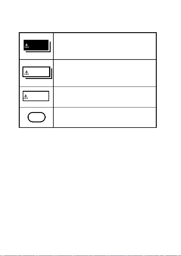
The following symbols in this manual indicate the
relative importance of cautions and warnings.
Indicates that incorrect operation
DANGER
presents extreme danger of accident
resulting in death or serious injury to the
user.
Indicates that incorrect operation
WARNING
presents a significant hazard that could
result in serious injury or death to the
user.
Indicates that incorrect operation
CAUTION
presents a possibility of injury to the user
or damage to the instrument.
Indicates advisory items related to
NOTE
performance or correct operation of the
instrument.
――――――――――――――――――――――――
Safety

―――――――――――――――――――――――――――
Safety Symbols
The symbol printed on the instrument
indicates that the user should refer to a
corresponding topic in the manual (marked
with the symbol) before using the
relevant function.
In the manual, the symbol indicates
particularly important information that the
user should read before using the instrument.
Indicates AC (Alternating Current).
Indicates DC (Direct Current).
Indicates both DC (Direct Current) and AC
(Alternating Current).
Indicates a device which is doubleinsulated.
Indicates that the instrument may be connected
to or disconnected from a live circuit.
f.s. (maximum display or scale value, or length of scale)
Signifies the maximum display (scale) value or the
length of the scale (in cases where the scale consists
of unequal increments or where the maximum value
cannot be defined).
In general, this is the range value (the value written
on the range selector or equivalent) currently in use.
rdg. (displayed or indicated value)
Signifies the value actually being measured, i.e., the
value that is currently indicated or displayed by the
measuring instrument.
dgt. (resolution)
Signifies the smallest display unit on a digital
measuring instrument, i.e., the value displayed when
the last digit on the digital display is "1".
v
――――――――――――――――――――――――
Safety

vi
―――――――――――――――――――――――――――
Measurement categories (Overvoltage
categories)
This instrument complies with CAT III safety
requirements.
To ensure safe operation of measurement
instruments, IEC 61010 establishes safety standards
for various electrical environments, categorized as
CAT I to CAT IV, and called measurement
categories. These are defined as follows.
CAT I : Secondary electrical circuits connected to
an AC electrical outlet through a
transformer or similar device.
CAT II : Primary electrical circuits in equipment
connected to an AC electrical outlet by a
power cord (portable tools, household
appliances, etc.)
CAT III : Primary electrical circuits of heavy
equipment (fixed installations) connected
directly to the distribution panel, and
feeders from the distribution panel to
outlets.
CAT IV : The circuit from the service drop to the
service entrance, and to the power meter
and primary overcurrent protection device
(distribution panel).
――――――――――――――――――――――――
Safety

―――――――――――――――――――――――――――
vii
Higher-numbered categories correspond to electrical
environments with greater momentary energy. So a
measurement device designed for CAT III
environments can endure greater momentary energy
thanadevicedesignedforCATII.
Using a measurement instrument in an environment
designated with a higher-numbered category than
that for which the instrument is rated could result in
a severe accident, and must be carefully avoided.
Never use a CAT I measuring instrument in CAT II,
III, or IV environments.
The measurement categories comply with the
Overvoltage Categories of the IEC60664 Standards.
――――――――――――――――――――――――
Safety
viii
―――――――――――――――――――――――――――
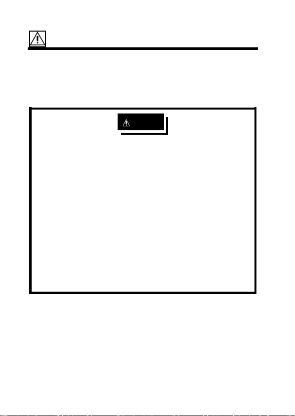
Attentions During Use
Follow these precautions to ensure safe operation
and to obtain the full benefits of the various
functions.
DANGER
・ Use clamp testers only on power lines up to 600
Vrms, to avoid short-circuits and accidents that
could result in injury or death.
・ Always connect the clamp sensor to the
secondary side of a breaker. On the secondary
side of a breaker, even if the lines are shorted
the breaker can trip and prevent an accident.
On the primary side, however, the current
capacity may be large, and in the event of a
short-circuits there may be a serious accident.
・ When using an AC adapter, use only the
specified HIOKI model 9445-02 (SA10-0910N,
SINO-AMERICAN) or 9445-03 (for EU) (SA100910G, SINO-AMERICAN).
――――――――――――――――――――――――
Attentions During Use
―――――――――――――――――――――――――――
ix
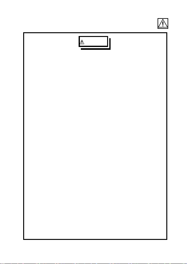
WARNING
・ To avoid electric shock, do not allow the
product to get wet, and do not use it when your
hands are wet.
・ To avoid electric shock when measuring live lines,
wear appropriate protective gear, such as insulated
rubber gloves, boots and a safety helmet.
・ During current measurement, to avoid an
electric shock accident, do not connect the test
leads to the product.
・ Do not input voltage exceeding 600 Vrms (1000
V max.).
・ To avoid electric shock when replacing the
batteries, first disconnect the clamp portion
from the object to be measured. Also, before
using the product after replacing the batteries,
replace the cover and screw.
・ When replacing the batteries, be sure to insert
them with the correct polarity. Otherwise, poor
performance or damage from battery leakage
could result.
・ To avoid the possibility of explosion, do not short
circuit, disassemble or incinerate batteries.
・ Handle and dispose of batteries in accordance
with local regulations.
・Do not use the instrument where it may be exposed
to corrosive or combustible gases. The instrument
may be damaged or cause an explosion.
――――――――――――――――――――――――
Attentions During Use

x
―――――――――――――――――――――――――――
CAUTION
・ This is a precision instrument: do not clamp any
foreign objects in the end of the clamp core, or
insert anything in the core gap.
・ To avoid damage to the product, protect it from
vibration or shock during transport and handling,
and be especially careful to avoid dropping. Do not
exert excessive pressure on the clamp sensor or
attempt to wedge the sensor into a tight spot for
measurement.
・ Before using the product the first time, verify that it
operates normally to ensure that the no damage
occurred during storage or shipping. If you find any
damage, contact your dealer or HIOKI
representative.
・ To avoid damage to the product, do not exceed the
maximum input current rating, which depends on
the frequency of the current being measured (see
Fig.4 of Chapter 3) Be careful about the evolution
of heat, when the input frequency is high.
・ Do not use the product if the battery is exhausted
(when the
mark lights in the display area). Be
sure to replace the exhausted battery with a new
one.
・ When replacing the battery, make sure that the
metal battery snap fitting is firmly connected. If the
metal fitting is loose, adjust it and recheck the
connection. If it isn't connected securely, the power
may not be turned on, and a power may be turned
off during the use.
・ Adjustments and repairs should be made only by
technically qualified personnel.
――――――――――――――――――――――――
Attentions During Use

―――――――――――――――――――――――――――
xi
CAUTION
・ For the inside memory protection, make sure the
power is turned off before plugging in or unplugging
the AC adapter.
・ This product is designed for indoor use, and operates
reliably from 0
to 40 .
・ Do not store or use the product where it could be
exposed to direct sunlight, high temperature or
humidity, or condensation. Under such conditions,
the product may be damaged and insulation may
deteriorate so that it no longer meets specifications.
・ Accurate measurement may be impossible in
NOTE
locations subject to strong external magnetic fields,
such as transformers and high-current conductors, or
in locations subject to strong external electric fields,
such as radio transmission equipment.
・ Gently wipe dirt from the surface of the unit with a
soft cloth moistened with a small amount of water
or mild detergent.
Do not try to clean the unit using cleaners
containing organic solvents such as benzine, alcohol,
acetone, ether, ketones, thinners, or gasoline. They
may cause discoloration or damage.
・ When not in use for a long time, to prevent possible
corrosion caused by battery leakage, remove the
batteries before storage.
――――――――――――――――――――――――
Attentions During Use

xii
―――――――――――――――――――――――――――
Organization of This Manual
Chapter 1
Product Outline
Explains the parts and functions of the unit.
Chapter 2
Measurement Procedure
Explains how to use the 3285 for measurement.
Chapter 3
Specifications
Lists the specifications of the 3285 CLAMP ON
AC/DC HiTESTER.
Chapter 4
Battery Replacement
Explains how to replace the battery used to power
the 3285.
Chapter 5
AC Adapter (Optional)
Explains how to use the AC adapter.
Chapter 6
Attaching the Hand Strap
Explains how to attach the hand strap, for easy
handling of the unit in the field.
Chapter 7
Troubleshooting
Describes how to check before requesting service.
Chapter 8
Service
Explains how to get the unit serviced.
――――――――――――――――――――――――
Organization of This Manual

―――――――――――――――――――――――――――
Chapter 1
Product Outline
1.1 Product Outline
The 3285 CLAMP ON AC/DC HiTESTER makes it
possible to measure DC, AC or AC+DC current in
live power lines without tapping into or connecting
the lines. Using a one-chip microprocessor, the
tester provides many functions, including an
automatic zero adjust function that changes a
troublesome task into a one-touch operation. An AC
adapter connection terminal and an output terminal
areequippedsothatyouareabletomeasureby
connecting to other instruments such as recorders.
1
――――――――――――――――――――――――
Chapter 1 Product Outline

2
―――――――――――――――――――――――――――
1.2 Features
・ A multi-function microcomputer
The built-in microcomputer offers various functions
in a compact form.
・ Display of true rms values
The true rms value conversion circuit allows
accurate measurement of currents with distorted
waveforms.
・ Measurement for AC/DC
The unit permits measurement of AC superimposed
on DC, as well as measurement of half- and fullwave rectification.
・ Peak measurement
Allows measurement of peak hold values for either
voltage or current. Transitional peak values can
also be measured.
・ REC function
Displays the maximum and minimum measured
values.
・ Output terminal
You can record current or frequency by connecting
a recorder or an oscilloscope to the built-in output
terminal.
Current (Record output: REC, Waveform output:
MON)
Frequency (Record output: REC)
・ Dual-power source
The unit operates on either a battery power or an
AC power source.
――――――――――――――――――――――――
Chapter 1 Product Outline

―――――――――――――――――――――――――――
1.3 Parts and Functions
Top and Side View
⑩
3
⑰
①
②
⑪
⑱
③
④
⑤
⑥
⑨
⑧
⑦
⑫
⑭
⑯
⑬
⑮
――――――――――――――――――――――――
Chapter 1 Product Outline

4
―――――――――――――――――――――――――――
①
POWER
・ Used to turn power on/off
・ To disable the auto power-off function, hold
and press
②
POWER
key
, when you turn power on.
HOLD
・ Switches current modes as follow.
DCA AC+DCAACA
RANGE
③
・ Switches between auto and manual ranges in
measurements of current, voltage, or frequency.
・ Switches manual ranges.
・ Displays a cursor on the bar graph to show the
selected range.
・ The current ranges are 200 A and 2000 A. The
voltage ranges are 30 V, 300 V and 600 V. The
frequency ranges are 10 Hz, 100 Hz and 1000 Hz.
HOLD
④
・ Used to suspend or inactivate the screen-updating
function.
・ To disable the auto power-off function when
powering on, hold
OUTPUT
⑤
HOLD
and press
POWER
.
・ Allows voltage output during current measurement or
frequency measurement in a current mode.
・ The auto power-off function is inactivated.
REC
(Record output)
(Auto power-off inactive)
(Except for DC A)
MON
(Waveform output)
(Auto power-off inactive)
Light turned off
(Auto power-off active)
APS
annunciator is on.
・ You can find how much the battery power remains
on the bar graph, when you press
OUTPUT
in a
current mode.
――――――――――――――――――――――――
Chapter 1 Product Outline
―――――――――――――――――――――――――――
SLOW/PEAK/Hz
⑥
・ SLOW slows down screen updating (once per three
seconds).
・ FAST speeds up screen updating (four times per
".
second). There isn't an annunciator "
FAST
Instead, the unit symbol blinks.
・ PEAK measures peak values (Peak Hold).
・ Hz measures frequency (in AC or AC+DC mode).
⑦
・ Switches voltage modes as follows.
DC V AC+DC VAC V
MAX/MIN
⑧
・ Displays the maximum value (MAX), the minimum
value (MIN), or the average value (AVE)ofthe
maximum and minimum values for the recording
(REC) function.
・ MAX displays the maximum measured value after
the REC function is activated.
・ MIN displays the minimum measured value after the
REC function is activated.
・ AVE displays the average value of the maximum
and minimum measured values after the REC
function is activated.
・ The auto power-off function is disabled in the REC
function.
5
――――――――――――――――――――――――
Chapter 1 Product Outline

6
―――――――――――――――――――――――――――
0ADJ/RESET
⑨
・ Performs auto-zero-adjustment in DC A, AC+DC A
and DC V modes.
・ Resets data when measuring peak values. Reset all
the data in a REC function.
・ If zero is not indicated under no input in the AC A,
AC+DC A, AC V or AC+DC V modes, press
HOLD
, then press
0ADJ/RESET
to perform a zero-
cancel correction.
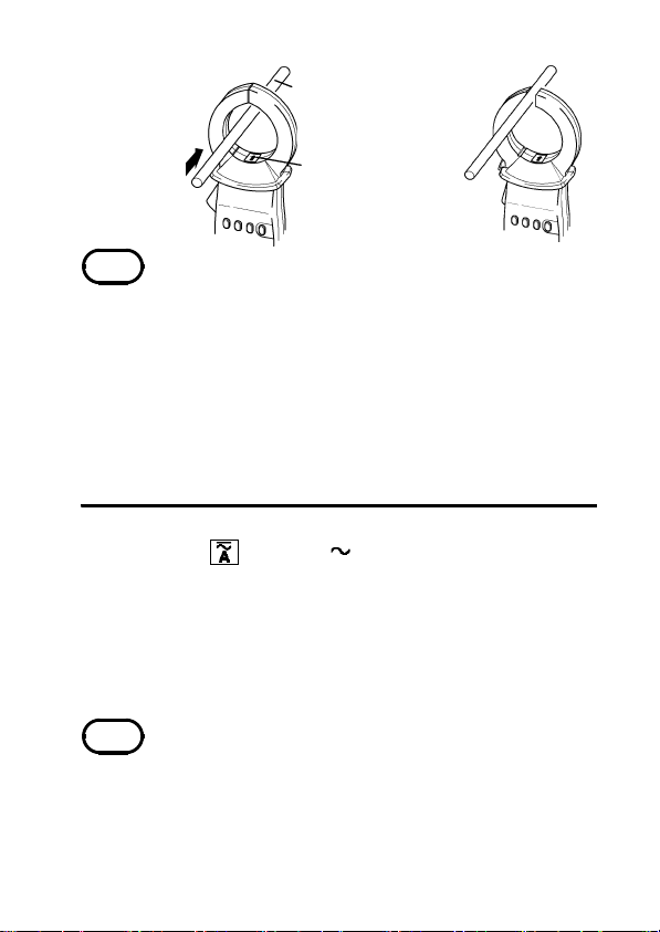
⑩ Clamp sensor
・ To measure current, open the top ends of the clamp
sensor by gripping the lever ⑪. Then position the
conductor to be measured at the center of the clamp
sensor and firmly close the clamp sensor.
⑪ Lever
・ Used to open and close the clamp sensor.
――――――――――――――――――――――――
Chapter 1 Product Outline

―――――――――――――――――――――――――――
⑫ Display (LCD)
Direct Current (DC)
Alternating Current (AC)
Alternating Current and Direct Current
(AC+DC)
Auto-zero-adjustment or zero-cancel
ADJ
correction function is active
Battery low warning
Data hold function
HOLD
Waveform output (AC) is active
MON
Recording output (DC) is active
REC
Auto power off function
APS
AUTO Auto-range
SLOW Counter update once every 3 seconds
REC Record function
MAX Maximum value
MIN Minimum value
AVE Average value = (MAX + MIN)/2
Hz Frequency
V Voltage
PEAK Wave peak value
RMS True root mean square value
――――――――――――――――――――――――
Chapter 1 Product Outline
7

8
―――――――――――――――――――――――――――
A Current
hour 1 hour/segment (bar graph)
min 1 minute/segment (bar graph)
Input over (bar graph)
⑬ Output terminal
Connected to the optional 9094 OUTPUT CORD to
provide output during a current measurement or a
frequency measurement in a current mode.
⑭ AC adapter connection terminal
Connected to the optional 9445-02 or 9445-03 AC
ADAPTER to perform measurements for no battery
or a long term measurement.
⑮ Voltage measurement terminal (V and COM
terminals)
Connected to the 9207-10 TEST LEAD (red and
black, supplied with the unit) to measure voltage.
⑯ Slide knob
Slide up to use the voltage measurement terminal or
slide down to use the output terminal or AC adapter
connection terminal. Move until a click is heard.
⑰ Back case
To replace the battery, remove the two screws.
⑱ Hand strap
Attach to get a better grip on the unit.
――――――――――――――――――――――――
Chapter 1 Product Outline

―――――――――――――――――――――――――――
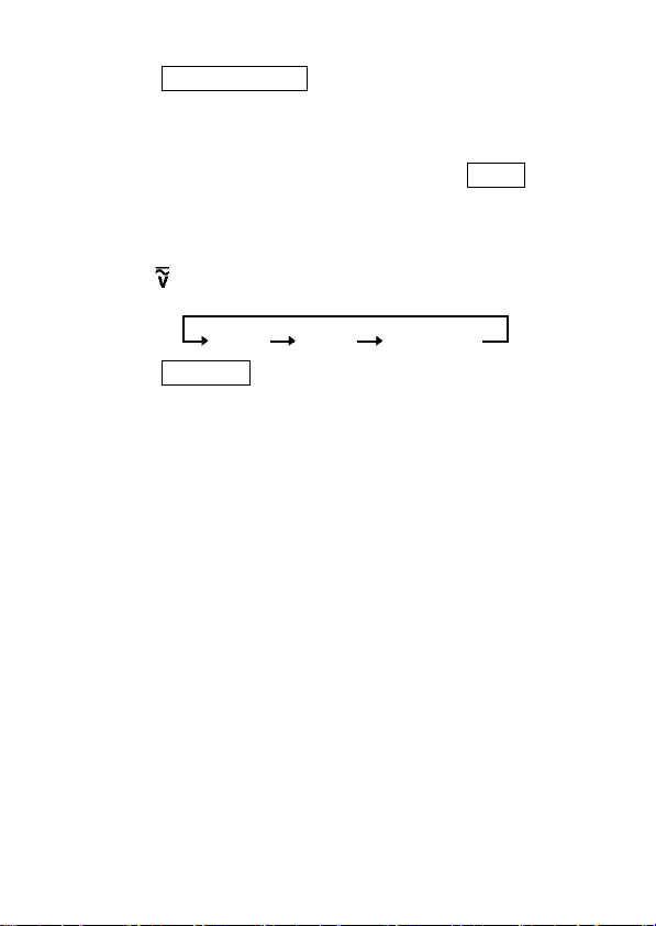
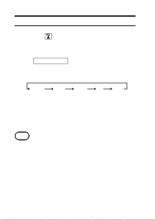
1.4 Flowchart of Key Operations
1.4.1 Current Measurements Mode
key
RANGE key
SLOW/PEAK/
Hz key
DC A AC+DC AAC A
AUTO range
200.0 A range
2000 A range
SLOW
FAST
PEAK
NORMAL
AUTO range
200.0 A range
2000 A range
SLOW
FAST
PEAK
Hz
NORMAL
AUTO range
200.0 A range
2000 A range
SLOW
FAST
PEAK
Hz
NORMAL
9
MAX/MIN key
OUTPUT key
0ADJ/RESET
key
HOLD+0ADJ/
RESET key
MAX
MIN
AVE
Instantaneous
value
OFF
MON
Auto-zeroadjustment
Disabled zero-cancel
MAX
MIN
AVE
Instantaneous
value
OFF
REC
MON
Disabled Auto-zero-
correction
MAX
MIN
AVE
Instantaneous
value
OFF
REC
MON
adjustment
zero-cancel
correction
* Neither "FAST" or "NORMAL" annunciator is on
the display.
――――――――――――――――――――――――
Chapter 1 Product Outline
10
―――――――――――――――――――――――――――
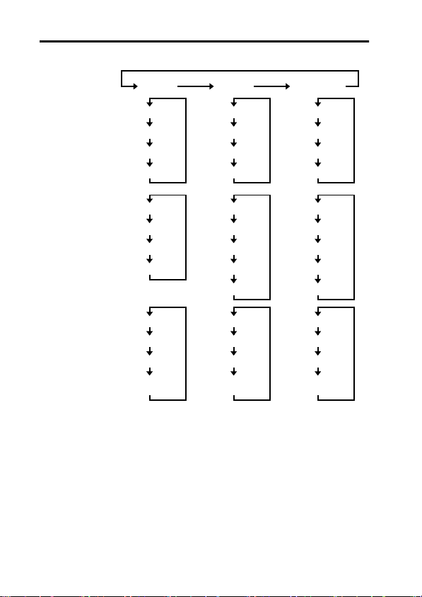
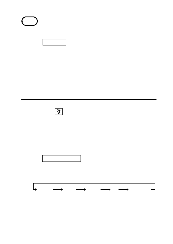
1.4.2 Voltage Measurements Mode
Vkey
RANGE key
DC V AC+DC VAC V
AUTO range
30.00 V range
300.0 V range
600 V range
AUTO range
30.00 V range
300.0 V range
600 V range
AUTO range
30.00 V range
300.0 V range
600 V range
SLOW/PEAK/
Hz key
MAX/MIN key
OUTPUT key
0ADJ/RESET
key
HOLD+0ADJ/
RESET key
SLOW
FAST
PEAK
NORMAL
MAX
MIN
AVE
Instantaneous
value
Disabled Disabled Disabled
Auto-zeroadjustment
Disabled zero-cancel
SLOW
FAST
PEAK
Hz
NORMAL
MAX
MIN
AVE
Instantaneous
value
Disabled Disabled
correction
Instantaneous
value
SLOW
FAST
PEAK
Hz
NORMAL
MAX
MIN
AVE
zero-cancel
correction
* Neither "FAST" or "NORMAL" annunciator is on
the display.
――――――――――――――――――――――――
Chapter 1 Product Outline

―――――――――――――――――――――――――――
11
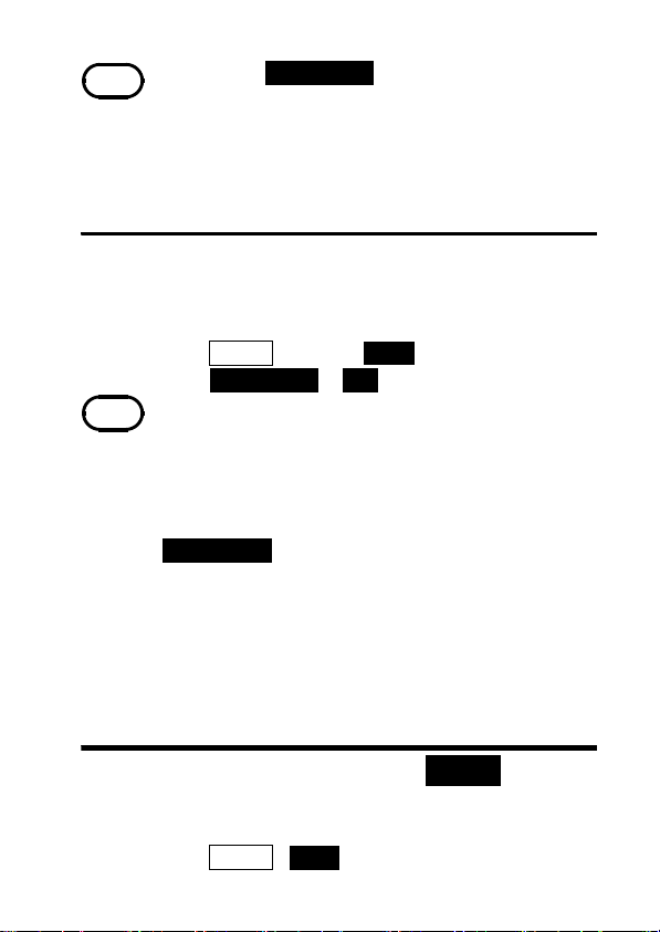
1.4.3 FrequencyMeasurements Mode
Current (AC A, AC+DC A) mode
Voltage (AC V, AC+DC V) mode
SLOW/PEAK/
Hz key
RANGE key
MAX/MIN key
OUTPUT key
0ADJ/RESET
key
SLOW
PEAKFAST
Hz NORMAL
Current mode Voltage mode
AUTO range
10.00 Hz range
100.0 Hz range
1000 Hz range
MAX
MIN
AVE
Instantaneous
value
OFF
REC
Disabled Disabled
AUTO range
10.00 Hz range
100.0 Hz range
1000 Hz range
MAX
MIN
AVE
Instantaneous
value
Disabled
――――――――――――――――――――――――
Chapter 1 Product Outline

12
―――――――――――――――――――――――――――
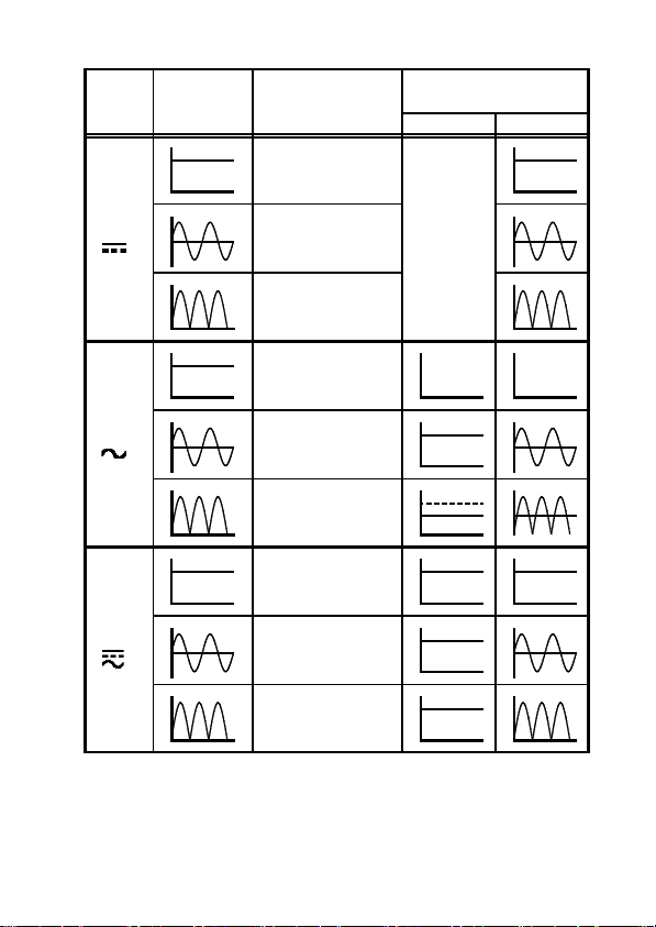
1.5 Modes
For voltage and current, three modes are provided:
DC (direct current, ), AC (alternating current, ),
and AC+DC (alternating current and direct current,
) modes. Select a proper mode according to the
waveform shown below:
――――――――――――――――――――――――
Chapter 1 Product Outline
―――――――――――――――――――――――――――
Mode
Input
waveform
Display
OUTPUT
(only for current mode)
REC MON
13
○Average value
displayed (with
0
polarity)
0
DC
(
AC
(
AC+DC
(
0
)
×Not measurable
Disabled
0
×Not measurable
0
×Not measurable
0
0
)
(zero displayed)
○RMS value
0
0
×Not measurable
0
0
0V
0
0V
0
0
0
○RMS value
0
0
)
(without polarity)
○RMS value
0 0
0
0
○RMS value
0
0 0
――――――――――――――――――――――――
Chapter 1 Product Outline

14
―――――――――――――――――――――――――――
――――――――――――――――――――――――
Chapter 1 Product Outline

―――――――――――――――――――――――――――
s
15
Chapter 2
Measurement
Procedure
2.1 Preparations
1. Remove the rear cover and insert a battery. (Refer to
"Chapter 4 Battery Replacement".)
2. Press
3. The DC current measurement mode is activated.
【Low battery voltage detection function】
POWER
segments of the display light up briefly. Then the
model name is shown, and the bar graph indicates
the battery condition.
After the
below a certain level, the power goes off
automatically. When this occurs,
displayed.
When power goes off after display of these marks,
replace the exhausted battery with a new one.
to turn the unit on. Verify that all
Fresh battery
Battery capacity 50%
Battery capacity 0
Beep tone sounds 3 time
mark lights and battery voltage drops
andLoare
bAtt
――――――――――――――――――――――――
Chapter 2 Measurement Procedure

16
)
―――――――――――――――――――――――――――
2.2 Current Measurement
・ Accurate measurement may be impossible in
NOTE
2.2.1 MeasuringDC Current(DC A
locations subject to strong external magnetic fields,
such as transformers and high-current conductors, or
in locations subject to strong external electric fields,
such as radio transmission equipment.
・ Make sure that only one conductor is clamped in
the center of the clamp sensor. If you clamp singlephase (2-wire) or three-phase (3-wire) lines together,
it will be impossible to measure.
・ The display may show a measured value bigger than
the actual value due to a magnet:c field interference.
The interference is less than 2 A during the
measurement.
1. Press
to display .
2. Switch between the auto range and the manual range
as necessary.
3. Press
0ADJ/RESET
to make an auto-zero-adjustment
(without clamping the measured conductor inside
the clamp sensor) with the clamp sensor firmly
closed. (see 2.5.1: Auto-zero-adjustment function).
annunciator lights to indicate that auto-zero-
ADJ
adjustment is complete. (If you make an auto-zeroadjustment in the auto range, two current ranges will
be adjusted in this mode.)
4. Open the top ends of the clamp core, orient the
current direction indicator on the clamp in the
current direction of the measured conductor, and
clamp the conductor so that it passes through the
center of the clamp core.
――――――――――――――――――――――――
Chapter 2 Measurement Procedure
―――――――――――――――――――――――――――
)
Measured conductor
Current direction
Current direction
indicator
・ The DC A mode permits only DC current
NOTE
measurements that does not include the AC
Wrong
17
component (see 1.5: Modes).
・ The 200 A range will display up to 250 A, however,
only the range from 10 A to 200 A can be displayed
with guaranteed accuracy.
・ At any range, gross errors may occur at 1% or
below of the range, whose accuracy is not
guaranteed, as a result of internal corrective
calculations.
2.2.2 MeasuringAC Current(AC A
1. Press to display .
2. Switch between the auto range and the manual range
as necessary.
3. Open the top ends of the clamp core and clamp the
measured conductor so that it passes through the
center of the clamp core.
・ Just after suspension of input, or when modes are
NOTE
switched under no input, the counter would not
become zero for about 10 seconds. This is normal
and simply reflects the workings of the internal
circuit. But you can measure with guaranteed
accuracy before the counter becomes zero.
――――――――――――――――――――――――
Chapter 2 Measurement Procedure
18
)
―――――――――――――――――――――――――――
・ Depending on ambient temperatures, the counter
NOTE
would not become zero under no input. If this
happens, perform a zero-cancel correction (2.5.2:
Zero-cancel correction function).
・ During a f.s. input, the measurement response speed
is about 250 ms during rise (0% to 90%) and about
500 ms (100% to 10%) during fall (2.2.5, Figs. 1
and 2).
・ The AC A mode does not allow measurement of DC
waveforms, full-wave rectification waveforms, halfwave rectification waveforms, or DC+AC
waveforms (See 1.5: Modes).
・ The 200 A range will display up to 250 A, however,
only the range from 10 A to 200 A can be displayed
with guaranteed accuracy.
・ At any range, gross errors may occur at 1% or
below of the range ,whose accuracy is not
guaranteed, as a result of internal corrective
calculations.
2.2.3 MeasuringAC/DC Current(AC+DC A
1. Press
2. Switch between the auto range and the manual range
as necessary.
3. Press
(without clamping the measured conductor inside
the clamp sensor) with the clamp sensor firmly
closed. (see 2.5.1: Auto-zero-adjustment function).
ADJ
adjustment is complete.
4. If the counter fails to become zero under no input,
press
perform a zero-cancel correction.
――――――――――――――――――――――――
Chapter 2 Measurement Procedure
to display .
0ADJ/RESET
to make an auto-zero-adjustment
annunciator lights to indicate that auto-zero-
HOLD
and then press
0ADJ/RESET
to

―――――――――――――――――――――――――――
19
5. Open the top ends of the clamp core and clamp the
measured conductor so that it passes through the
center of the clamp core.
・ Just after suspension of input, or when modes are
NOTE
switched under no input, the counter would not
become zero for about 10 seconds. This is normal
and simply reflects the workings of the internal
circuit. But you can measure with guaranteed
accuracy before the counter becomes zero.
・ Depending on ambient temperatures, the counter
would not become zero under no input. If this
happens, preform a zero-cancel correction (2.5.2:
Zero-cancel correction function).
・ The polarity of the input is not displayed, even if
DC current is measured in this mode. If the clamp
sensor is reoriented, the measured values may
change, but the values are within the guaranteed
accuracy. (In case that you would like to measure a
DC current which doesn't have AC components, you
should make the measurement in DC A mode.)
・ During a f.s. input, the measurement response speed
is about 250 ms during rise (0% to 90%) and about
500 ms (100% to 10%) during fall (2.2.5, Figs. 1
and 2).
・ The 200 A range will display up to 250 A, however,
only the range from 10 A to 200 A can be displayed
with guaranteed accuracy.
・ At any range, gross errors may occur at 1% or
below of the range,whose accuracy is not guaranteed
as a result of internal corrective calculations.
・ When displaying the current measured value during
a frequency output, the auto-zero-adjustment is
unavailable for the current measurement.
――――――――――――――――――――――――
Chapter 2 Measurement Procedure

20
―――――――――――――――――――――――――――
2.2.4 Peak Hold Measurement
1. Press and select a measurement mode for the
measured circuit.
2. In DC A and AC+DC A modes, make an auto-zeroadjustment by
0ADJ/RESET
3. Set to PEAK. The measurement mode is switched
by
SLOW/PEAK/Hz
.
as follows.
SLOW PEAKFAST
(The unit
symbol blinks.)
Hz
(Except
DC)
NORMAL
4. Switch between the auto and the manual range as
necessary. (If you are unable to estimate the peak
current value, start at the 2000A range.)
5. Before the measurement, press
0ADJ/RESET
to reset
the residual data.
6. Open the top ends of the clamp core and clamp the
measured conductor so that it passes through the
center of the clamp core.
・ The polarity of the input is not displayed during
NOTE
peak measurements. The measured values may
change if the clamp sensor is reoriented, but the
values are within the guaranteed accuracy.
・ For peak measurements, internal resetting occurs
every 250 ms. This may cause a peak detection
failure, depending on the timing.
・ Even after clamping, press
0ADJ/RESET
to reset the
data as necessary.
――――――――――――――――――――――――
Chapter 2 Measurement Procedure
―――――――――――――――――――――――――――
・ In case that the counter doesn't become zero under
NOTE
no input in peak measurement mode, even though
you pressed
0ADJ/RESET
to reset the peak data, the
21
clamp sensor may be magnetized. Quit the peak
measurement mode, and perform the auto-zero
adjustment by
0ADJ/RESET
. Then make the
settings again. (A few counts would remain,even if
you push
0ADJ/RESET
.)
・ The hold value does not change, unless a larger
value is measured, but be careful to avoid accidental
loss of data resulting from the auto power-off
function. (See 2.9: Auto power-off function.)
・ Use the REC function to make measurements longer
than the auto power OFF time.
・ You cannot output peak values. When pressing
OUTPUT
during peak measurement, the present
measured value is outputted.
・ To check transitional peak value, press
MAX/MIN
to shift to the Instantaneous value (no annunciator).
MAX AVEMIN Instantaneous value
(no annunciator)
2.2.5 Output Function
An output of AC/DC 1 V is produced for 2000count on the full scale of each current range.
Select either
(waveform output).
(In DC A mode, only
Modes)
1. Press
2. Press
RANGE
OUTPUT.RECorMON
and activates the output function, automatically
disabling the auto power-off function. (
annunciator is turned off.)
――――――――――――――――――――――――
(record output) or
REC
is available. See 1.5:
MON
MON
to set the current range.
annunciator lights
APS
Chapter 2 Measurement Procedure

22
―――――――――――――――――――――――――――
3.
OUTPUT
REC (Record output)
(Auto power-off inactive)
switches the output modes.
MON (Wa veform output)
(Auto power-off inactive)
(Auto power-off active)
Light turned off
4. Set a range based on the unit's measurement range
and other instruments, such as recorders. A
conversion table for ranges is provided below.
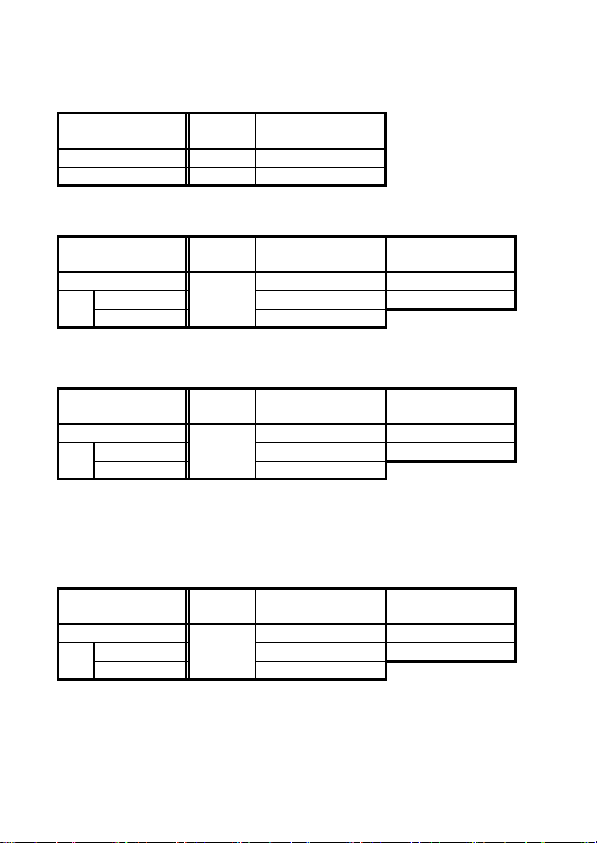
Range /DIV 10 mV 20 mV 50 mV 0.1 V 0.2 V 0.5 V 1V
2000 A range 20 A 40 A 100 A 200 A 400 A 1000 A 2000 A
200 A range 2A 4A 10 A 20 A 40 A 100 A 200 A
※ The figures are current values per DIV of a measuring instrument,
WARNING
such as a recorder.
To avoid damage to the unit, do not short the
output terminal and do not input voltage to the
output terminal.
・ Before using the output function, be sure to press
NOTE
OUTPUT
, confirming that either
RECorMON
annunciator is on. Output is made even when both
annunciators are off, but the power will be
automatically off in approximately 10 minutes, since
the auto power-off function is activated.
・ If
OUTPUT
is pressed in an auto range (AUTO),
the current range is set as the key is pressed.
(AUTO annunciator is turned off.)
・ Errors may occur or output values unless an auto-
zero-adjustment is done in DC A mode.
・ The zero-cancel function does not affect output.
Thus, voltage would be generated because of an
ambient temperature, even if there is no input.
――――――――――――――――――――――――
Chapter 2 Measurement Procedure

―――――――――――――――――――――――――――
NOTE
・
outputs are analog outputs. The output
REC
response time during a f.s. input differs between rise
23
(0% to 90%, about 250 ms) and fall (100% to 10%,
about 500 ms). (Figs 2 and 3) As the measured
value is small to the range response time becomes
long.
・ Changes of counter updating rate, peak
measurement, frequency measurement, recording,
and data holding are possible when generating
current measurement output. (But output will be
changed during mode shift, range shift, shift to
voltage measurement mode, or auto-zeroadjustment.)
・ Use the optional 9094 OUTPUT CORD to connect
the unit to a recorder.
・ For recorders, use over 1 MΩ input impedance.
Low impedances will affect indicated values.
・ Even if you press while recording frequency
measurements, output is still for the frequency. To
obtain a current output, press
OUTPUT
to disable
the frequency output, then make new settings.
・ For a long term measurement, use the optional
9445-02 or 9445-03 AC ADAPTER.
・ When the AC adapter is used and there is a large
amount of noise in the power line, the display may
show several counts or noise may be present in the
output. In such a case, connect the ground terminal
of the level recorder or the L side of the input to
ground.
――――――――――――――――――――――――
Chapter 2 Measurement Procedure
24
k
―――――――――――――――――――――――――――
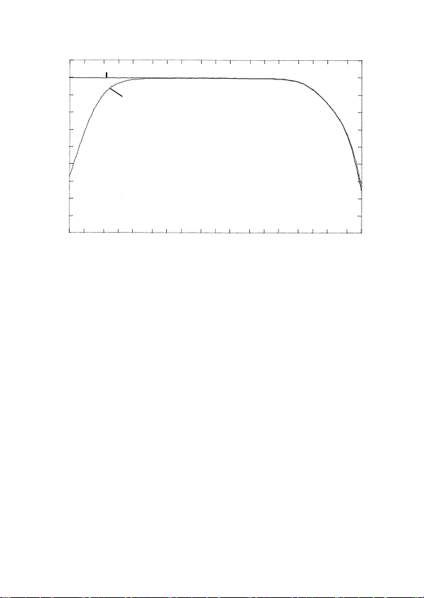
GAIN [dB]
2
AC+DC A (MON)
0
-2
-4
-6
-8
-10
-12
-16
-18
100m 1 10 100 1k 10k 100
AC A (MON)
FREQUENCY [Hz]
Fig. 1 Frequency Characteristics of Current Output
――――――――――――――――――――――――
Chapter 2 Measurement Procedure

―――――――――――――――――――――――――――
Output waveInput wave
200 A
100 A
250 ms
25
Fig. 2 Waveform of Output Response (Rise)
Output waveInput wave
500 ms
Fig. 3 Waveform of Output Response (Fall)
――――――――――――――――――――――――
Chapter 2 Measurement Procedure
26
)
―――――――――――――――――――――――――――
2.3 Voltage Measurement
2.3.1 MeasuringDC Voltage(DC V
1. Press to display .
2. Slide the slide cover up using the slide knob. Next,
insert the red test lead to V and the black test lead
to COM of the voltage measurement terminal.
3. Switch between the auto range and the manual range
as necessary.
4. If the counter does not show zero, switch to the range
you will use (manual range), and press
to perform an auto-zero adjustment.
annunciator lights to indicate that auto-zero-
ADJ
adjustment is complete.
5. Carefully contact the test leads to a circuit.
・ You can perform the auto-zero-adjustment up to 4%
NOTE
of the range.
・ When you switch ranges after auto-zero adjustment,
deviation of the adjustment value will prevent
accurate measurement. Always perform the auto-zero
adjustment after switching ranges. (Do not perform
auto-zero adjustment when using the auto range.)
・ A lit - annunciator indicates that potential is
higher at the black test lead than at the red test lead.
・ The DC V mode permits only DC voltage
measurements that does not include the AC
component (see 1.5: Modes).
・ Every range will display up to 125% of the range,
however, only the range from 10% to 100% can be
displayed with guaranteed accuracy.
・ At any range, gross errors may occur at 1% or below
of the range, whose accuracy is not guaranteed, as a
result of internal corrective calculations.
0ADJ/RESET
――――――――――――――――――――――――
Chapter 2 Measurement Procedure

―――――――――――――――――――――――――――
)
27
2.3.2 MeasuringAC Voltage(AC V
1. Press to display ~.
2. Slide the slide cover up using the slide knob. Next,
insert the red test lead to V and the black test lead
to COM of the voltage measurement terminal.
3. Switch between the auto range and the manual range
as necessary.
4. Carefully contact the test leads to a circuit.
・ Just after suspension of input, or when modes are
NOTE
switched under no input, the counter would not
become zero for about 10 seconds. This is normal
and simply reflects the workings of the internal
circuit. But you can measure with guaranteed
accuracy before the counter becomes zero.
・ Depending on ambient temperatures, the counter
would not become zero under no input, if this
happens, press
HOLD
and then press
0ADJ/RESET
to perform a zero-cancel correction. (2.5.2: Zerocancel correction function)
・ During a f.s. input, the measurement response speed
is about 250 ms during rise (0% to 90%) and about
500 ms (100% to 10%) during fall (2.2.5, Figs. 1
and 2).
・ The AC V mode does not allow measurement of DC
waveforms, full-wave rectification waveforms, halfwave rectification waveforms, or DC+AC
waveforms (See 1.5: Modes).
・ Every range will display up to 125% of the range,
however, only the range from 10% to 100% can be
displayed with guaranteed accuracy.
・ At any range, gross errors may occur at 1% or
below of the range, whose accuracy is not
guaranteed, as a result of internal corrective
calculations.
――――――――――――――――――――――――
Chapter 2 Measurement Procedure

28
)
―――――――――――――――――――――――――――
2.3.3 MeasuringAC/DC Voltage(AC+DC V
1. Press to display .
2. Slide the slide cover up using the slide knob. Next,
insert the red test lead to V and the black test lead
to COM of the voltage measurement terminal.
3. Switch between the auto range and the manual range
as necessary.
4. If the counter does not show zero even after display
stabilizes, switch to the range you will use (a manual
range), press
perform a zero-cancel correction. (2.5.2: Zero-cancel
correction function)
5. Carefully contact the test leads to a circuit.
・ When you switch ranges after zero-cancel
NOTE
correction, deviation of the correction value will
prevent accurate measurement. (Do not perform a
zero-cancel correction when using the auto range.)
If you accidentally perform zero-cancel correction while
using the auto range, repeat zero-cancel correction after
turning the power off once and then on again.
・ Just after suspension of input, or when modes are
switched under no input, the counter would not
become zero for about 10 seconds. This is normal
and simply reflects the workings of the internal
circuit. But you can measure with guaranteed
accuracy before the counter becomes zero.
・ The polarity of the input is not displayed, even if DC
voltage is measured in this mode. If the connections
of test leads are moved, the measured values may
change, but the values are within the guaranteed
accuracy. (In case that you would like to measure
DC voltage which doesn't have AC components, you
should make the measurement in DC V mode.)
・ During a f.s. input, the measurement response speed
is about 250 ms during rise (0% to 90%) and about
500 ms (100% to 10%) during fall (2.2.5, Figs. 1
and 2).
HOLD
and then press
0ADJ/RESET
to
――――――――――――――――――――――――
Chapter 2 Measurement Procedure

―――――――――――――――――――――――――――
・ Every range will display up to 125% of the range,
NOTE
however, only the range from 10% to 100% can be
29
displayed with guaranteed accuracy.
・ At any range, gross errors may occur at 1% or below
of the range, whose accuracy is not guaranteed, as a
result of internal corrective calculations.
2.3.4 Peak Hold Measurement
1. Press
measured circuit.
2. Slide the slide cover up using the slide knob. Next,
insert the red test lead to V and the black test lead
to COM of the voltage measurement terminal.
3. Set to PEAK. The measurement mode is switched
by
and select a measurement mode for the
SLOW/PEAK/Hz
as follow.
SLOW PEAKFAST
(The unit
symbol blinks.)
Hz
(Except
DC)
NORMAL
4. Switch between the auto and the manual range as
necessary. (If you are unable to estimate the peak
voltage value, start at the 600 V range.)
5. Before the measurement, press
0ADJ/RESET
to reset
the residual data.
・ The polarity of the input is not displayed during
NOTE
peak measurements. If the connections of test leads
are moved, the measured values may change, but the
values are within the guaranteed accuracy.
・ For peak measurements, internal resetting occurs
every 250 ms. This may cause a peak detection
failure, depending on the timing.
・ To check transitional peak value, press
MAX/MIN
to shift to the Instantaneous value (no annunciator).
・ In peak measurement mode, zero-adjustment is
disabled.
MAX AVEMIN Instantaneous value
――――――――――――――――――――――――
Chapter 2 Measurement Procedure
(no annunciator)
30
―――――――――――――――――――――――――――
2.4 Frequency Measurement
2.4.1 FrequencyMeasurement in Current Mode
1. Press and select AC or AC+DC, depending on
the circuit to be measured.
2. If the current range of the measured circuit is
known, set the current range to the manual range.
3.
SLOW/PEAK/Hz
follows. Select Hz by pressing the key. (The unit
symbol A blinks, and a current value is displayed on
the bar graph.)
switches the annunciators as
SLOW PEAKFAST
(The unit
symbol blinks.)
Hz RMS
4. Switch the auto range and the manual range as
necessary.
5. Open the top ends of the clamp core and clamp the
measured conductor so that it passes through the
center of the clamp core.
・ At the 100 Hz and 1000 Hz ranges, ---- appears on
NOTE
the counter when the frequency is lower than 10 Hz.
・ ---- appears on the counter, if the frequency is lower
than 1 Hz.
・ O. L. appears on the counter, if the frequency is
higher than 1 kHz.
・ If an input value is significantly lower than the
range, an accurate measurement may not be
achieved, resulting in ----, O. L. or display
fluctuations.
――――――――――――――――――――――――
Chapter 2 Measurement Procedure
―――――――――――――――――――――――――――
・ The 10 Hz range or 100 Hz range will display up to
NOTE
125% of each range, however, only the range from
31
10% to 100% can be displayed with guaranteed
accuracy.
・
MAX/MIN
does not affect output values.
・ The frequencies, whose waveforms are special such
as inverters, would not be measurable, when the
carrier frequencies are lower than several kHz.
・ Full-wave rectification indicates twice the actual
value, due to an AC coupling in the internal circuit.
・ It would take time to stabilize the counter,
depending on the frequency range or the input
frequency.
2.4.2 FrequencyMeasurement in Voltage Mode
1. Press
the circuit to be measured.
2. If the voltage range of the measured circuit is
known, set the voltage range to the manual range.
2. Slide the slide cover up using the slide knob. Next,
insert the red test lead to V and the black test lead
to COM of the voltage measurement terminal.
4.
SLOW/PEAK/Hz
follows. Select Hz by pressing the key. (The unit
symbol V blinks, and a voltage value is displayed
on the bar graph.)
and select AC or AC+DC, depending on
switches the annunciators as
SLOW PEAKFAST
(The unit
symbol blinks.)
Hz NORMAL
4. Switch between the auto range and the manual range
as necessary.
5. Carefully contact the test leads to a circuit.
――――――――――――――――――――――――
Chapter 2 Measurement Procedure

32
y
―――――――――――――――――――――――――――
・ At the 100 Hz and 1000 Hz ranges, ---- appears on
NOTE
the counter when the frequency is lower than 10 Hz.
・ ---- appears on the counter, if the frequency is lower
than 1 Hz.
・ O. L. appears on the counter, if the frequency is
higher than 1 kHz.
・ If an input value is significantly lower than the
range, on accurate measurement may not be
achieved, resulting in ----, O. L. or display
fluctuations.
・ The 10 Hz range or 100 Hz range will display up to
125% of each range, however, only the range from
10% to 100% can be displayed with guaranteed
accuracy.
・ The frequencies, whose waveforms are special such
as inverters, would not be measurable, when the
carrier frequencies are lower than several kHz.
・ Full-wave rectification indicates twice the actual
value, due to an AC coupling in the internal circuit.
・ It would take time to stabilize the counter,
depending on the frequency range or the input
frequency.
2.4.3 Output Function For Frequenc
Frequency measurement output is available only in
current modes.
An output of DC 1 V is produced for 1000-count on
the full scale of the frequency range. An output is
produced twice per second, the same as display
refreshing. (The output waveform will be in step
form for a large frequency change, due to D/A
outputs.)
1. To make settings, refer to the frequency
measurement procedure in a current mode.
――――――――――――――――――――――――
Chapter 2 Measurement Procedure

―――――――――――――――――――――――――――
2. Press
OUTPUT.REC
annunciator lights and
33
activates the output function.
3. The auto power-off function is automatically
disabled. (
annunciator is tuned off.)
APS
4. Set a range based on the unit's measurement range
and other instruments, such as recorders.
Range/DIV 10 mV 20 mV 50 mV 0.1 V 0.2 V 0.5 V 1V
1000 Hz range 10 Hz 20 Hz 50 Hz 100 Hz 200 Hz 500 Hz 1000 Hz
100 Hz range 1Hz 2Hz 5Hz 10 Hz 20 Hz 50 Hz 100 Hz
10 Hz range 0.1 Hz 0.2 Hz 0.5 Hz 1Hz 2Hz 5Hz 10 Hz
※ The figures are frequency values per DIV of a measuring instrument,
・ Before using the output function, be sure to press
NOTE
OUTPUT
on. When
, confirming that
annunciator is off, the output is
REC
REC
such as a recorder.
annunciator is
for current measured values.
・ No auto-zero-adjustment is available in AC +DC A
mode.
・ If
OUTPUT
is pressed in the auto range (AUTO),
the frequency range is set as the key is pressed.
(AUTO annunciator is turned off.)
・ If you press
, the frequency output is also
HOLD
held.
・ The display "----" corresponds to 0 V output and the
display "O.L." corresponds to 1.36 V output
respectively.
・ To connect a recorder, use the optional 9094
OUTPUT CORD.
・ For recorders, use over 1 MΩ input impedance.
・ Current measurements will continue to be recorded
when you shift to the frequency measurement mode
during current measurement recording. To obtain
frequency measurements, press
OUTPUT
to disable
the current measurement mode, then make the new
settings.
――――――――――――――――――――――――
Chapter 2 Measurement Procedure

34
―――――――――――――――――――――――――――
・ For a long term measurement, use the optional
NOTE
9445-02 or 9445-03 AC ADAPTER.
・ When the AC adapter is used and there is a large
amount of noise in the power line, the display may
show several counts or noise may be present in the
output. In such a case, connect the ground terminal
of the level recorder or the L side of the input to
ground.
2.5 Auto-Zero-Adjustment/
Zero-Cancel Correction Function
2.5.1 Auto-Zero-Adjustment Function
NOTE
The auto-zero-adjustment function is used to adjust
offsets in the internal circuit automatically that
result from temperature characteristics or clamp
sensor magnetization. The clamp core is
magnetized during a large DC current measurement,
or when a powerful magnet is placed close to the
clamp core.
1. Wait until the counter is stable under no input.
Then, press
・ You can perform the auto-zero-adjustment, if the
counter displays within ±45 A in a current mode.
・ When there is an input or the counter decreases, the
measurement accuracy will be spoiled by pressing
0ADJ/RESET as well as the accurate auto-zeroadjustment. If inaccurate auto-zero-adjustment is
performed, perform the correct procedure again.
・ It would take approximately 20 seconds to stabilize
the counter in AC+DC A mode.
・ Use the zero-cancel correction function if the
counter fails to revert to zero after correct auto-zeroadjustment in AC+DC A mode.
0ADJ/RESET.ADJ
annunciator lights.
――――――――――――――――――――――――
Chapter 2 Measurement Procedure
―――――――――――――――――――――――――――
NOTE
・ If you press
0ADJ/RESET
zero-adjustment in the internal circuit, the auto-zero-
again during the auto-
35
adjustment is canceled.
・Do not perform auto-zero adjustment when using
auto range in the DC V mode. Always switch to the
range you will use (a manual range) before
performing the adjustment.
2.5.2 Zero-Cancel Correction Function
Use the zero-cancel correction function when the
counter fails to become zero under no input in AC
A, AC+DC A, AC V, or AC+DC V mode.
1. Press
2. Press
NOTE
0ADJ/RESET.ADJ
・Do not perform a zero-cancel correction when using
the auto range. Always switch to the range you will
HOLD
to display
annunciator.
HOLD
annunciator blinks.
use (a manual range) before performing the
adjustment.
・ When there is an input or the counter decreases, the
measured values will be evaluated lower by pressing
0AJD/RESET
.
・ If the counter is zero, the zero-cancel correction
function does not work.
・ In AC+DC A mode, the zero-cancel correction
function does not work, unless auto-zero-adjustment
is complete.
・ The zero-cancel correction function works only on
the counter. It will not calibrate output values.
2.6 Data Hold Function HOLD
This function freezes the counter at any desired
point for easy reading.
1. Press
HOLD.HOLD
――――――――――――――――――――――――
annunciator lights on the
Chapter 2 Measurement Procedure
36
―――――――――――――――――――――――――――
display and the digital display value and bar graph
display are maintained.
The data hold function is available for all
measurements.
To cancel the data hold function, press
If you press
RANGE
during the data hold function,
HOLD
again.
the bar graph display the present range.
2.7 Alteration of Counter Updates
The counter is updated twice per second when
powering on. The counter update may be altered
according to measurement conditions.
SLOW/PEAK/Hz
follows:
SLOW PEAK
FAST
(The unit
annunciator blinks.)
changes an annunciator as
Hz
(Except DC)
NORMAL
2.7.1 SLOW mode
If the counter fluctuates rapidly and is hard to read,
you can select a slower update rate (once every 3
seconds) by pressing
SLOW/PEAK/Hz
.
2.7.2 FAST mode
・ For current measurements and voltage measurements, the
counter is updated four times per second in FAST mode.
You can measure abrupt changes such as starting currents.
・ The unit symbol A or V blinks.
・ To facilitate reading when measuring a starting
current, use the record (REC) function to hold the
maximum value (MAX).
――――――――――――――――――――――――
Chapter 2 Measurement Procedure

―――――――――――――――――――――――――――
37
2.8 Recording Function REC
Use the recording function to hold the maximum
and minimum measured values and
maximum/minimum averages.
1. Measurement indicated value
Pressing the
MAX/MIN
current or voltage activates the recording function.
REC flashes and the product saves the maximum
value (MAX), minimum value (MIN), and average
value (AVE) in internal memory from the instant
you press the
MAX/MIN
MAX/MIN
key with the recording function activated
switches the display as shown below. If MAX,
MIN, or AVE is not displayed, an instantaneous
value is assumed.
MAX→MIN→AVE→Instantaneous value
(no annunciator)
Data (MAX, MIN, AVE) remains displayed while
the display is switched. If maximum or minimum
data is updated in the meantime, however, the data
values will change.
With the recording function activated, the auto
power-off function remains disabled. (APS off.)
The average value (AVE) displayed is calculated by:
Average Value = [(Maximum value + Minimum
Value)/2].
If the recording function is activated and
Instantaneous value (no annunciator) selected after
you activate PEAK mode with the
key, you can see the fluctuation of the peak.
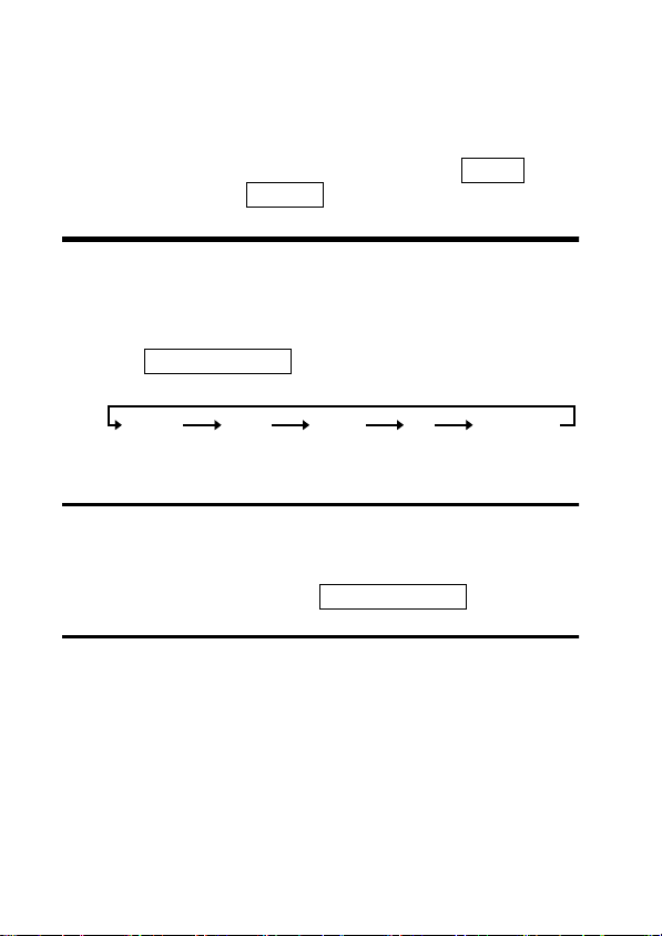
2. Display of Elapsed Time
key during measurements of
key. Pressing the
SLOW/PEAK/Hz
――――――――――――――――――――――――
Chapter 2 Measurement Procedure

38
―――――――――――――――――――――――――――
When you press the
MAX/MIN
key to activate the
recording function, the bar graph segments flash and
the elapsed time appears.
When "min" is shown in the right-hand corner of
the bar graph, each segment of the bar graph
corresponds to one minute. Every time one minute
elapses, one segment of the flashing bar graph goes
on. When all segments on the bar graph go on, the
elapsed time is 30 minutes.
When the elapsed time exceeds 30 minutes, one
segment of the flashing bar graph goes off every
time one minute elapses.
When the segments left of a flashing segment
remain on: the number of "on" segments represents
the elapsed time (0 ~ 29).
The illustration below shows when 20 minutes have
elapsed:
When the segments right of a flashing segment
remain on: the number of "off" segments (+30)
represents the elapsed time (30 ~ 59).
The illustration below shows when 50 minutes have
elapsed:
When digital display switches the average value
(AVE) to a instantaneous value when you press the
MAX/MIN
key, the right corner of the bar graph
indicates hours. In this mode, each segment of the
bar graph corresponds to one hour. The way to read
the bar graph here is similar to reading it in
minutes. When all bar graph segments remain on,
――――――――――――――――――――――――
Chapter 2 Measurement Procedure

―――――――――――――――――――――――――――
39
the elapsed time is 29 hours.
The illustration below shows when one hour, 40
minutes have elapsed.
3. Deactivation of Recording Function
key deactivates the recording
Pressing the
function.
HOLD
HOLD
goes on,
stops flashing and
REC
goes on, and the elapsed time stops incrementing.
While the recording function is being deactivated,
data is not updated, even if the clamp sensor is
disconnected from the conductor.
Pressing the
HOLD
key again cancels
HOLD
display and activates the recording function again,
with
flashing again.
REC
4. Resetting of Recording Function
Push
0ADJ/RESET
key, in the case that data is
reset during the recording function action.
5. Cancellation of Recording Function
To cancel the recording function, press the related
function key (A or V) for the measurement in progress.
Once the recording function is canceled, the auto
power-off function becomes effective. (
APS
goes on.)
・ For a long term measurement, use the optional
NOTE
9445-02 or 9445-03 AC ADAPTER, or check how
much the battery power remains by pressing
OUTPUT
.
・ When starting the recording function (REC)inan
auto range, the range is set as the range of when
that pushed
MAX/MIN
――――――――――――――――――――――――
key.
Chapter 2 Measurement Procedure

40
―――――――――――――――――――――――――――
・ When you need minimum value and average value
NOTE
data, make sure to activate the recording function
during measurement. If the function is activated
when there is no input, the minimum value will
remain zero. Also, when deactivating the recording
key to terminate
function, press the
HOLD
measurement once the minimum value and average
value data have been read. If you disconnect the
clamp or test lead from the circuit under
measurement without deactivating the recording
function beforehand, the minimum value will be
zero.
・ When the unit is turned off, accumulated data are
lost.
2.9 Auto Power-Off Function APS
annunciator is displayed, the auto
・ When the
power-off function is active.
・ If no key is pressed for about 10 minutes, the unit
turns itself off automatically.
・ Immediately before turning off automatically,
annunciator blinks and a beep tone is heard for
about 30 seconds.
・ By pressing any key except
extend the powered state for another 10 minutes.
Procedure for disabling the auto power-off
function.
・ Press
you turn power on.
・ Use the recording function (REC) by pressing
MAX/MIN
・ Press
――――――――――――――――――――――――
Chapter 2 Measurement Procedure
APS
POWER
OUTPUT
with holding down
.
in a current mode.
POWER
,youwill
HOLD
APS
,when

―――――――――――――――――――――――――――
41
2.10 Battery Low Warning
・ When this indication appears, the battery is depleted,
which can lead to inaccurate measurements. Replace
the battery to ensure accuracy.
・ To check remaining battery life, check the bar graph,
when powering on or by pressing
bar graph provides a rough approximation of
remaining battery life. Be careful for the battery life
especially before using an output function for a long
term or when using the REC function.
・ Batteries tend to increase in voltage somewhat when
left unused for a long period. Even if the battery
warning annunciator becomes temporarily off after
the period, replace the battery as soon as possible.
If the battery is not replaced at this point in time,
the annunciator may not light up immediately on the
next occasion. Replace a new battery before it ruins
a measurement or causes some other inconvenience.
(See Chapter 4: Battery replacement)
OUTPUT
.The
2.11 Beep Tone
To disable the beep tone, hold
turning the unit on by pressing
RANGE
POWER
when
.
――――――――――――――――――――――――
Chapter 2 Measurement Procedure

42
―――――――――――――――――――――――――――
――――――――――――――――――――――――
Chapter 2 Measurement Procedure

―――――――――――――――――――――――――――
43
Chapter 3
Specifications
3.1 Measurement Specifications
Temperature and humidity
for guaranteed accuracy
Guaranteed accuracy period 1 year, or opening and closing of
3.1.1 Current Measurement Specifications
○ Current display accuracy
① DC current A (mean value)
Range
(Accuracy Range)
200A(10.0~200.0A) 0.1A ±(1.3%rdg.+3dgt.)
2000A(100~2000A) 1A ±(1.3%rdg.+3dgt.)
② AC current Arms (true rms)
Range
(Accuracy Range)
200A(10.0~200.0A) 0.1A ±(1.3%rdg.+3dgt.) ±(2.0%rdg.+5dgt.)
(100~1800A)
2000A
(1800~2000A) ±(2.3%rdg.+3dgt.)
③ AC+DC current Arms (true rms)
Range
(Accuracy Range)
200A(10.0~200.0A) 0.1A ±(1.3%rdg.+13dgt.) ±(2.0%rdg.+7dgt.)
(100~1800A)
2000A
(1800~2000A) ±(2.3%rdg.+13dgt.)
Resolution
Resolution
1A
Resolution
1A
23℃±5℃ (73 ±9 ),
80% RH or less
the Clamp Sensor 10,000 times,
whichever comes first
DC
45~66Hz 10~45,66~1kHz
±(1.3%rdg.+3dgt.) ±(2.0%rdg.+5dgt.)
DC,45~66Hz 10~45,66~1kHz
±(1.3%rdg.+13dgt.) ±(2.0%rdg.+7dgt.)
――――――――――――――――――――――――
Chapter 3 Specifications
44
―――――――――――――――――――――――――――
○ Output accuracy
① DC current A (mean value)
Range
(Accuracy Range)
200A(10.0~200.0A) 1V/f.s. ±(1.3%rdg.+5mV)
2000A(100~2000A) 1V/f.s. ±(1.3%rdg.+5mV)
MON DC
② AC current Arms (true rms)
MON
Range
(Accuracy Range)
200A(10.0~200.0A)
(100~1800A) ±(1.3%rdg.+5mV) ±(2.0%rdg.+5mV)
2000A
(1800~2000A) ±(2.3%rdg.+5mV)
MON 45~66Hz 10~45,66~1kHz
±(1.3%rdg.+5mV) ±(2.0%rdg.+5mV)
AC1V/f.s.
frequency bandwidth:0.5~15kHz (±3dB)
REC
Range
(Accuracy Range)
200A(10.0~200.0A)
(100~1800A) ±(1.3%rdg.+10mV) ±(2.0%rdg.+10mV)
2000A
(1800~2000A) ±(2.3%rdg.+10mV)
Output response (during a f.s. input):
REC 45~66Hz 10~45,66~1kHz
DC1V/f.s.
Rise response time (0% to 90%) 250 ms or less
±(1.3%rdg.+10mV) ±(2.0%rdg.+10mV)
Fall response time(100% to 10%)500 ms or less
③ AC+DC current Arms (true rms)
MON
Range
(Accuracy Range)
200A(10.0~200.0A)
(100~1800A) ±(1.3%rdg.+5mV) ±(2.0%rdg.+5mV)
2000A
(1800~2000A) ±(2.3%rdg.+5mV)
MON DC,45~66Hz 10~45,66~1kHz
±(1.3%rdg.+5mV) ±(2.0%rdg.+5mV)
1V/f.s.
frequency bandwidth:DC~15kHz (±3dB)
――――――――――――――――――――――――
Chapter 3 Specifications

―――――――――――――――――――――――――――
45
REC
Range
(Accuracy Range)
200A(10.0~200.0A)
(100~2000A) ±(1.3%rdg.+10mV) ±(2.0%rdg.+10mV)
2000A
(1800~2000A) ±(2.3%rdg.+10mV)
Output response (during a f.s. input):
REC DC,45~66Hz 10~45,66~1kHz
DC1V/f.s.
±(1.3%rdg.+10mV) ±(2.0%rdg.+10mV)
Rise response time (0% to 90%) 250 ms or less
Fall response time(100% to 10%)500 ms or less
○ Peak measurement accuracy (Peak hold function)
During continuous input of sine waves
① DC current A peak (wave peak value)
Range
(Accuracy Range)
200A(10~500A)
(100~2300A) ±(1.3%rdg.+7dgt.)
2000A
(2300~2840A) ±(6.0%rdg.+7dgt.)
Resolution
1A
DC
±(1.3%rdg.+7dgt.)
② AC current A peak (wave peak value)
Range
(Accuracy Range)
200A(10~500A)
(100~2300A) ±(1.3%rdg.+7dgt.) ±(2.0%rdg.+7dgt.)
2000A
(2300~2840A) ±(6.0%rdg.+7dgt.)
Resolution
1A
45~66Hz 10~45,66~1kHz
±(1.3%rdg.+7dgt.) ±(2.0%rdg.+7dgt.)
③ AC+DC current A peak (wave peak value)
Range
(Accuracy Range)
200A(10~500A)
(100~2300A) ±(1.3%rdg.+7dgt.) ±(2.0%rdg.+7dgt.)
2000A
(2300~2840A) ±(6.0%rdg.+7dgt.)
Resolution
1A
DC,45~66Hz 10~45,66~1kHz
±(1.3%rdg.+7dgt.) ±(2.0%rdg.+7dgt.)
――――――――――――――――――――――――
Chapter 3 Specifications

46
―――――――――――――――――――――――――――
○ Frequency measurement Hz
Display accuracy
Range
(Accuracy Range)
10Hz(1.00~10.00Hz)
100Hz(10.0~100.0Hz)
1000Hz(100~1000Hz)
Resolution
0.01Hz ±(0.3%rdg.+1dgt.)
0.1Hz ±(0.3%rdg.+1dgt.)
1Hz ±(1.0%rdg.+1dgt.)
Output accuracy
Range
(Accuracy Range)
10Hz(1.00~10.00Hz)
100Hz(10.0~100.0Hz)
1000Hz(100~1000Hz)
Output response: 4 seconds or less at 1000Hz and 100Hz
ranges, 6 seconds or less at 10Hz range
REC
DC1V/f.s. ±(1.3%rdg.+3mV)
DC1V/f.s. ±(1.3%rdg.+3mV)
DC1V/f.s. ±(2.0%rdg.+3mV)
――――――――――――――――――――――――
Chapter 3 Specifications
―――――――――――――――――――――――――――
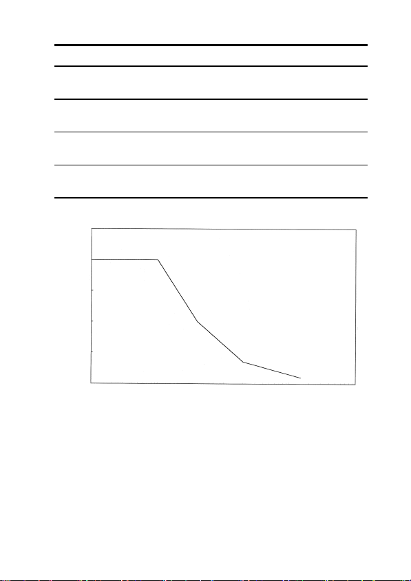
Current Specifications
Maximum permissible
current
Effect of conductor
position
External magnetic
field interference
Maximum rated
voltage to earth
2500
2000
1500
1000
500
0
10 100 1k 10k 100k
2000 Arms continuous, 2840 Amax.
See Fig.4
within ±0.7% (in any direction from
sensor center)
AC 400 A/m (external magnetic fields)
corresponds to 2 A or less (display)
max. 600 Vrms
47
Frequency [Hz}
Fig.4 Frequency-dependent deletion characteristics
――――――――――――――――――――――――
Chapter 3 Specifications

48
―――――――――――――――――――――――――――
3.1.2 Voltage Measurement Specifications
○ Voltage display accuracy
① DC voltage V (mean value)
Range
(Accuracy Range)
30V(3.00~30.00V) 0.01V ±(1.0%rdg.+3dgt.)
300V(30.0~300.0V) 0.1V ±(1.0%rdg.+3dgt.)
600V(60.0~600V) 1V ±(1.0%rdg.+3dgt.)
② AC voltage Vrms (true rms)
Range
(Accuracy Range)
30V(3.00~30.00V) 0.01V ±(1.0%rdg.+3dgt.) ±(1.5%rdg.+5dgt.)
300V(30.0~300.0V) 0.1V ±(1.0%rdg.+3dgt.) ±(1.5%rdg.+5dgt.)
600V(60.0~600V) 1V ±(1.0%rdg.+3dgt.) ±(1.5%rdg.+5dgt.)
③ AC+DC voltage Vrms (true rms)
Range
(Accuracy Range)
30V(3.00~30.00V) 0.01V ±(1.0%rdg.+13dgt.) ±(1.5%rdg.+13dgt.)
300V(30.0~300.0V) 0.1V ±(1.0%rdg.+7dgt.) ±(1.5%rdg.+7dgt.)
600V(60.0~600V) 1V ±(1.0%rdg.+7dgt.) ±(1.5%rdg.+7dgt.)
○ Peak measurement accuracy (Peak hold function)
During continuous input of sine waves
① DC voltage V peak (wave peak value)
Range
(Accuracy Range)
30V(3.0~75.0V) 0.1V ±(1.0%rdg.+7dgt.)
300V(30~750V) 1V ±(1.0%rdg.+7dgt.)
600V(60~1000V) 1V ±(1.0%rdg.+7dgt.)
② AC voltage V peak (wave peak value)
Range
(Accuracy Range)
30V(3.0~75.0V) 0.1V ±(1.0%rdg.+7dgt.) ±(1.5%rdg.+7dgt.)
300V(30~750V) 1V ±(1.0%rdg.+7dgt.) ±(1.5%rdg.+7dgt.)
600V(60~1000V) 1V ±(1.0%rdg.+7dgt.) ±(1.5%rdg.+7dgt.)
Resolution
Resolution
Resolution
Resolution
Resolution
DC
45~66Hz 10~45,66~1kHz
DC,45~66Hz 10~45,66~1kHz
DC
45~66Hz 10~45,66~1kHz
――――――――――――――――――――――――
Chapter 3 Specifications

―――――――――――――――――――――――――――
49
③ AC+DC voltage V peak (wave peak value)
Range
(Accuracy Range)
30V(3.0~75.0V) 0.1V ±(1.0%rdg.+7dgt.) ±(1.5%rdg.+7dgt.)
300V(30~750V) 1V ±(1.0%rdg.+7dgt.) ±(1.5%rdg.+7dgt.)
600V(60~1000V) 1V ±(1.0%rdg.+7dgt.) ±(1.5%rdg.+7dgt.)
Resolution
DC,45~66Hz 10~45,66~1kHz
○ Frequency measurement Hz
Display accuracy
Range
(Accuracy Range)
10Hz(1.00~10.00Hz)
100Hz(10.0~100.0Hz)
1000Hz(100~1000Hz)
Resolution
0.01Hz ±(0.3%rdg.+1dgt.)
0.1Hz ±(0.3%rdg.+1dgt.)
1Hz ±(1.0%rdg.+1dgt.)
3.2 General Specifications
○ Accessory Functions:
Auto-zero adjustment
function
Zero cancel function Pressing
Recording Maximum (MAX), minimum (MIN),
Data hold Data hold function
Auto power-off Automatic shutdown after 10.5±1
Beep tone ON/OFF
Pressing
0ADJ/RESET
once in DC A or
AC+DC A mode.
holding
0ADJ/RESET
HOLD
once with
in AC or AC+DC
mode.
average (AVE) value display selectable
for current, voltage and frequency
measurements
minutes. Beep tone warning before the
shutdown. Extending and disabling
possible.
○ Display LCD panel
Digital counter 2500 counts max. (current)
3750 counts max. (voltage)
1250 counts max. (frequency)
――――――――――――――――――――――――
Chapter 3 Specifications

50
―――――――――――――――――――――――――――
Bar graph display 35 segments
Over-range display "
Battery low warning
Data hold annunciator
Auto power-off
annunciator
Units A, V, Hz
Zero suppression 5 counts
Display update rate Digital counter
Bar graph approx. 4 times/second
Display response time
(the range is fixed,
0% to 100%)
Range switching Auto range, manual (fixed) range
Output impedance 300Ω max.
Circuit dynamic
characteristics
(crest factor)
Withstand voltage Clamp sensor - Chassis, clamp sensor -
Effect of conducted
radio-frequency
electromagnetic field
(in 3 V)
Location for use Indoor, altitude up to 2000 m
" (bar graph)
O.L.
HOLD
APS
NORMAL approx. 2 times/second
SLOW approx. 1 time/3 seconds
FAST approx. 4 times/second
Current, Voltage: 1 s max.
Frequency:
1 s max. (1000 Hz, 100 Hz range)
2.5 s max. (10 Hz range)
(selectable).
2.5 max. (1.42 for 2000 A range, 1.7 for
600 V range)
circuit: 5312 Vrms AC for 15 seconds
Current measurement: -3 A or less
――――――――――――――――――――――――
Chapter 3 Specifications

―――――――――――――――――――――――――――
Applicable standards Safety:
Maximum conductor
diameter for
measurement
Operating temperature
and humidity range
Temperature
characteristics
Storage temperature
range
Power source One 6F22 (006P) 9 V battery or 9445-02
Maximum power
consumption
Battery life Approx. 25 hours (continuous, no load)
External dimensions Approx. 62W×260H×39D mm
Mass Approx. 540 g
Accessories 9207-10 TEST LEAD (red and black) 1
――――――――――――――――――――――――
EN61010-1:2001
Voltage input: Pollution level 2,
measurement category III (expected
transient overvoltage: 6000 V)
EN61010-031:2002
EN61010-2-032:2002
Type A current sensor
EN60529:1991 IP40 (protected against
access to hazardous parts with a wire)
EMC:
EN61326:1997+A1:1998+A2:2001
+A3:2003
EN61000-3-2:2000
EN61000-3-3:1995+A1:2001
φ55 mm max.
0to40℃ (32 to 104 ),
80%RH or less (no condensation)
In 0 to 40℃ range: 0.1×accuracy
specifications/℃
-10 to 50℃
(14 to 122
AC ADAPTER (SA10-0910N, SINOAMERICAN) or 9445-03 AC ADAPTER
(EU) (SA10-0910G, SINO-AMERICAN)
110 mVA
Approx. 2.44"W×10.24"H×1.54"D
Approx. 19.0 oz.
9345 CARRYING CASE 1
Hand Strap 1
6F22(006P) 1
Instruction manual 1
, no condensation)
Chapter 3 Specifications
51

52
―――――――――――――――――――――――――――
Options 9445-02 AC ADAPTER
(SA10-0910N, SINO-AMERICAN)
9445-03 AC ADAPTER (EU)
(SA10-0910G, SINO-AMERICAN)
9094 OUTPUT CORD
――――――――――――――――――――――――
Chapter 3 Specifications

―――――――――――――――――――――――――――
53
Chapter 4
Battery
Replacement
CAUTION
Do not fix the back casing screws too tightly.
The torque about 0.5N・m is recommended.
1. Remove the two fastening screws of the rear cover,
using a Phillips screwdriver.
2. Remove the rear cover.
3. Remove the old battery without pulling the codes of
the snap.
4. Securely connect the battery to the battery snap.
5. Replace the rear cover and tighten the fastening
screws.
――――――――――――――――――――――――
Chapter 4 Battery Replacement

54
―――――――――――――――――――――――――――
――――――――――――――――――――――――
Chapter 4 Battery Replacement

―――――――――――――――――――――――――――
55
Chapter 5
AC Adapter
(Optional)
Fully insert the optional 9445-02 AC ADAPTER
into the AC adapter connection terminal.
・ The adapter may be used either with or without a
NOTE
――――――――――――――――――――――――
battery.
・ Use of a battery enables continuous measurement if
the AC power source temporarily becomes
unavailable, due to a blackout or some other reason.
・ When the power supply changes the battery to the
AC adapter such as back from a blackout, the
following would be shown,
1.
2. REC output waveform during frequency
3. Peak hold measurement:
output waveform during current
MON
measurement:
After the output shifts for approximately 10 ms,
the accurate output will be obtained.
It is recommended that
A mode should be used, when you would like to
make a long term measurement on DC A and a
blackout is likely to happen.
measurement:
After the output shifts for approximately 10 ms,
the accurate output will be obtained.
An inaccurate big value will be held.
Chapter 5 AC Adapter (Optional)
output in AC+DC
REC

56
―――――――――――――――――――――――――――
NOTE
All the phenomena are likely to happen, in the case
the battery voltage is lower than AC adapter voltage
(typ. 9 V) . It is recommended that a new battery
should be used, when the blackout seems to be
short.
・ The battery will be preferred as the power source
when the battery voltage is higher than the voltage
that supplied by the AC adapter (typically the case
with a brand-new battery). When battery voltage
dips below the AC adapter, the source automatically
switches over to the AC adapter.
・ The remaining battery charge (indicated by the bar
graph), when used with the AC adapter, is based on
the AC adapter voltage. It is not a display for
battery life in this case.
――――――――――――――――――――――――
Chapter 5 AC Adapter (Optional)

―――――――――――――――――――――――――――
57
Chapter 6
Attaching
The Hand Strap
Explains how to attach the hand strap, for easy
handling of the unit in the field.
――――――――――――――――――――――――
Chapter 6 Attaching The Hand Strap

58
―――――――――――――――――――――――――――
――――――――――――――――――――――――
Chapter 6 Attaching The Hand Strap

―――――――――――――――――――――――――――
59
Chapter 7
Troubleshooting
If the unit seems not to be working normally, check
the following points first before requesting service.
Symptom Battery Battery clip Test leads
Unit does not come
on.
indication appears
and unit immediately
turns off.
indication
appears.
Unit turns off during
use.*
Voltage cannot be
measured.
Remedy:
If problem persists,
request service.
* When APS (auto power-off) is effective, the unit is
NOTE
automatically shut down when no key is pressed for
about 10 minutes. (See 2.9, "Auto Power-Off
Function.")
Yes Yes
Yes
Yes
Yes Yes
Replace battery. Check
connection of
battery to clip.
Yes
Check test leads
for broken wire.
Repair is required if E.001 to E.005 is indicated on
the counter, when power is turned on.
――――――――――――――――――――――――
Chapter 7 Troubleshooting

60
―――――――――――――――――――――――――――
○ If no power is supplied:
・ If you're using a battery, check that it has sufficient
remaining power. (See 2.1: Preparations )
・ If you're using the AC adapter, check that it's fully
inserted into the AC adapter terminal and socket.
・ If no power is supplied by the AC adapter but the battery
works, the adapter may be defective. (Make sure that
you're using the 9445-02 or 9445-03 AC ADAPTER.)
○ The counter doesn't become zero:
・ If this occurs in DC A, AC+DC A or DC V modes, use
the auto-zero adjustment function (2.5.1).
・ If this occurs in AC A, AC V or AC+DC V mode, use the
zero-cancel correction function (2.5.2).
・ If this occures in AC + DC A mode after performing the
suto-zero-adjustment, perform the zero cancel correction
function (2.5.2).
――――――――――――――――――――――――
Chapter 7 Troubleshooting

―――――――――――――――――――――――――――
61
○ The measured value is smaller than the estimated
value.
Current measurement:
・ Check that the clamp sensor is firmly closed.
・ Check that the frequency of the measured circuit is within
the range provided in the specifications. (A smaller value
will be displayed for a high inverter carrier frequency.)
・ Check that the proper steps have been taken, according to
procedure described in 2.5.1: Auto-zero adjustment
function and 2.5.2: Zero-cancel correction function.
・ Check that you're using the proper mode. (See 1.5:
Modes.)
・ Check that the peak value is below the circuit dynamic
value provided in the specifications. (To check
transitional peak values, see Notes in 2.2.4 and 2.3.4:
Peak hold measurement.)
・ Check that the crest factor (peak value / RMS value) is
below the circuit dynamic value provided in the
specifications.
・ Check that the battery warning annunciator is off.
――――――――――――――――――――――――
Chapter 7 Troubleshooting

62
―――――――――――――――――――――――――――
Voltage measurement:
・ Check that the test leads are fully connected.
・ Check that the frequency of the measured circuit is within
the range provided in the specifications.
・ Check that the proper steps have been taken, according to
the procedure described in 2.5.1: Auto-zero adjustment
function and 2.5.2: Zero-cancel correction function.
・ Check that you're using the proper mode. (See 1.5:
Modes.)
・ Check that the peak value is below the circuit dynamic
value provided in the specifications. (To check
transitional peak value, see Notes in 2.2.4 and 2.3.4: Peak
hold measurement.)
・ Check that the crest factor (peak value / RMS value) is
below the circuit dynamic value provided in the
specifications.
・ Check that the battery warning annunciator is off.
Frequency measurement:
・ Check the waveform. Some special frequencies can't be
measured, such as those of inverters.
・ Check that the input value corresponds to 10% or more of
the range.
――――――――――――――――――――――――
Chapter 7 Troubleshooting

―――――――――――――――――――――――――――
63
○ The measured value is larger than the estimated
value.
Current measurement:
・ Check that you're using the proper range.
output function to
・ Examine the waveform using
MON
confirm that no components but the estimated frequency
are being used.
・ Check that the counter has been reset with
0ADJ/RESET
before peak measurement.
・ Look for magnetic fields, electrical fields or possible noise
sources near the unit.
・ The measured value would be bigger than the actual value
in case that the power supply changes the battery to the
AC adapter such as back from a blackout. (See Chapter 5:
AC Adapter (Optional) )
Voltage measurement:
・ Check that you're using the proper range.
・ Check that the counter has been reset with
0ADJ/RESET
before peak measurement.
・ Look for magnetic fields, electrical fields or possible noise
sources near the unit.
Frequency measurement:
・ Look for magnetic fields, electrical fields or possible noise
sources near the unit.
・ Check the waveform. Some special frequencies can't be
measured, such as those of inverters.
――――――――――――――――――――――――
Chapter 7 Troubleshooting
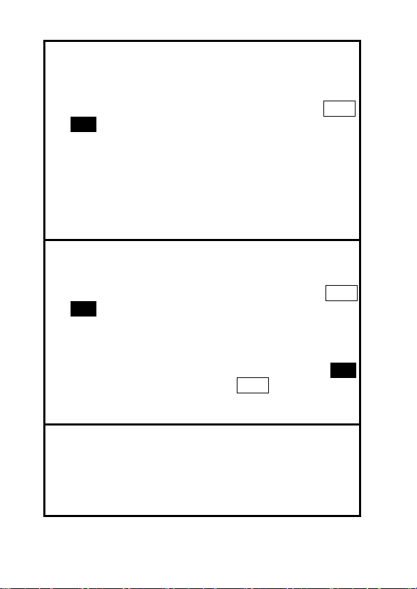
64
―――――――――――――――――――――――――――
○The output value is smaller than the estimated value.
・ Take the same precautionary steps as for the measured
value on the counter.
・ Make sure the 9094 OUTPUT CORD is fully connected.
・ Make sure you've selected the proper output mode (
or
).
MON
REC
・ Make sure the previously selected output mode (current or
frequency) is not active.
・ Check that the input impedance of the connected
measuring instrument is at least 1 MΩ.
・ Check that the mode of the connected measuring
instrument is not an AC coupling, or that the filter
function is disabled.
○ The output value is larger than the estimated value.
・ Take the same precautionary steps as for the measured
value on the counter.
・ Check that you've selected the proper output mode (
or
).
MON
REC
・ Check that the previously selected output mode (current
or frequency) is not active.
・ The output value would shift in case that that the power
supply changes the battery to the AC adapter during
output on current measurement on
REC
output on
MON
frequency measurement. (See Chapter 5: AC Adapter
(Optional) )
○ The measured value fluctuates.
・ Check that the measured circuit is stable.
・ During voltage measurements, check that the test leads are
fully connected.
・ Check the waveform. Some special frequencies can't be
measured, such as those of inverters.
――――――――――――――――――――――――
Chapter 7 Troubleshooting

―――――――――――――――――――――――――――
65
Chapter 8
Service
・ The minimum stocking period for replacement parts
is five years after end of production.
・ For information regarding service, please contact
your dealer or the nearest HIOKI representative.
・ If the unit is not functioning properly, check the
battery. If a problem is found, contact your dealer
or HIOKI representative. Pack the unit carefully so
that it will not be damaged during transport, and
write a detailed description of the problem. HIOKI
cannot bear any responsibility for damage that
occurs during shipment.
――――――――――――――――――――――――
Chapter 8 Service

66
―――――――――――――――――――――――――――
――――――――――――――――――――――――
Chapter 8 Service


HIOKI 3285 CLAMP ON AC/DC HiTESTER
Instruction Manual
Publication date: September 2006 Revised edition 10
Edited and published by HIOKI E.E. CORPORATION
Technical Sales Support Section
All inquiries to Sales and Marketing International
Department
81 Koizumi, Ueda, Nagano, 386-1192, Japan
TEL: +81-268-28-0562 / FAX: +81-268-28-0568
E-mail: os-com@hioki.co.jp
URL http://www.hioki.co.jp/
Printed in Japan 3285A980-10
・ All reasonable care has been taken in the production of this
manual, but if you find any points which are unclear or in
error, please contact your supplier or the Sales and
Marketing International Department at HIOKI headquarters.
・ In the interests of product development, the contents of this
manual are subject to revision without prior notice.
・ Unauthorized reproduction or copying of this manual is
prohibited.

HEAD OFFICE
81 Koizumi, Ueda, Nagano 386-1192, Japan
TEL +81-268-28-0562 / FAX +81-268-28-0568
E-mail: os-com@hioki.co.jp
URL http: //www.hioki.co.jp/
HIOKI USA CORPORATION
6 Corporate Drive, Cranbury, NJ 08512, USA
TEL +1-609-409-9109 / FAX +1-609-409-9108
Printed on recycled paper
 Loading...