

Page 1

取扱説明書
Instruction Manual
3284
クランプオンAC/DCハイテスタ
CLAMP ON AC/DC HiTESTER
2014年12月 発行 改訂17版
December 2014 Revised edition 17 3284A980-17 14-12H
Page 2

Page 3
――――――――――――――――――――――――――
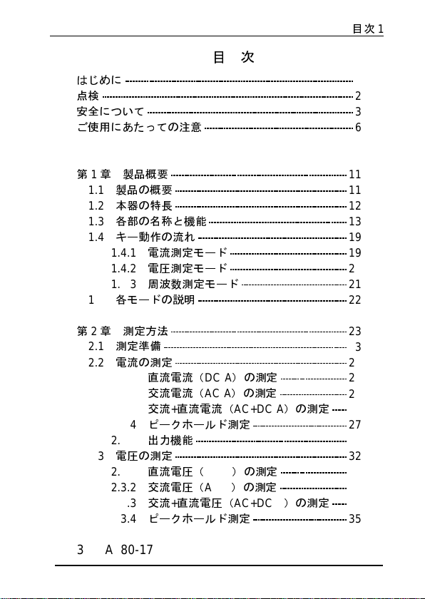
目次
目次
はじめに
点検
安全について
ご使用にあたっての注意
1
2
3
6
1
第1章 製品概要
1.1
製品の概要
1.2
本器の特長
1.3
各部の名称と機能
1.4
キー動作の流れ
1.4.1
1.4.2
1.4.3
1.5
各モードの説明
第2章 測定方法
2.1
測定準備
2.2
電流の測定
2.2.1
2.2.2
2.2.3
2.2.4
2.2.5
2.3
電圧の測定
2.3.1
2.3.2
2.3.3
2.3.4
電流測定モード
電圧測定モード
周波数測定モード
直流電流(
交流電流(
交流+直流電流(
ピークホールド測定
出力機能
直流電圧(
交流電圧(
交流+直流電圧(
ピークホールド測定
DC A
AC A
DC V
AC V
)の測定
)の測定
AC+DC A
)の測定
)の測定
AC+DC V
)の測定
)の測定
11
11
12
13
19
19
20
21
22
23
23
24
24
25
26
27
28
32
32
33
34
35
3284A980-17
―――――――――――――――――――――――
Page 4

目次
2
――――――――――――――――――――――――――
2.4
周波数測定
2.4.1
2.4.2
2.4.3
2.5
オートゼロ調整/ゼロキャンセル補正機能
2.5.1
2.5.2
2.6
データホールド機能
2.7
表示更新の変更
2.7.1 SLOW
2.7.2 FAST
2.8
レコード機能
2.9
オートパワーオフ機能
2.10
2.11
電池消耗警告
ブザー音
36
電流モードでの周波数測定
電圧モードでの周波数測定
出力機能
オートゼロ調整機能
ゼロキャンセル補正機能
HOLD
モード
モード
REC
44
APS
36
37
38
39
39
40
40
40
41
41
41
44
44
第3章仕様
3.1
3.1.1
3.1.2
3.2
第4章 電池の交換方法
第5章
第6章 ハンドストラップの付け方
第7章 故障とお考えになる前に
第8章 アフターサービス
測定仕様
一般仕様
電流測定仕様
電圧測定仕様
AC
アダプタ(別売)の使用
45
45
45
49
50
53
55
57
59
65
―――――――――――――――――――――――
Page 5
――――――――――――――――――――――――――
はじめに
1
このたびは、
をご選定いただき、誠にありがとうございます。この製品を
十分にご活用いただき、末長くご使用いただくためにも、取
扱説明書は、ていねいに扱い、いつも手元に置いてご使用く
ださい。
○お願い
本書の内容は、万全を期して作成しましたが、万一ご不明な
点や誤り、記載漏れなど、お気づきの点がありましたら、お
買上店(代理店)か最寄りの営業所にご連絡ください。
HIOKI“3284
クランプオン
AC/DC
ハイテスタ”
―――――――――――――――――――――――
Page 6
2
――――――――――――――――――――――――――
点検
本器がお手元に届きましたら、輸送中において異常または破
損がないか点検してからご使用ください。特に付属品および、
パネル面のスイッチ、キー、端子類に注意してください。万
一、破損あるいは仕様どおり動作しない場合は、お買上店(代
理店)か最寄りの営業所にご連絡ください。
○本体と付属品の確認
・本体
”
3284
クランプオン
・付属品
以下の標準付属品が添付されておりますので確認してくださ
い。
9399
L9207-10
ハンドストラップ
電池
6F22(006P) 1
取扱説明書
1
AC/DC
ハイテスタ”
携帯用ケース
テストリード(赤、黒)
1
1
1
○オプション
9094
9445-02 AC
出力コード
アダプタ
―――――――――――――――――――――――
Page 7
――――――――――――――――――――――――――
安全について
3
この測定器は
され、試験し、安全な状態で出荷されています。こ
の測定器は、操作方法を間違えると人身事故や機
器の故障につながる可能性があります。取扱説明
危険
書を熟読し、十分に内容を理解してから操作して
ください。万一事故があっても、弊社製品が原因で
ある場合以外は責任を負いかねます。
この取扱説明書には本器を安全に操作し、安全な状態に保つ
ために要する情報や注意事項が記載されています。本器をご
使用する前に下記の安全に関する事項をよくお読みください。
取扱説明書の注意事項には重要度に応じて以下の表記がされ
ています。
操作や取り扱いを誤ると、使用者が死亡または重
傷につながる危険性が極めて高いことを意味しま
危険
す。
操作や取り扱いを誤ると、使用者が死亡または重
警告
傷につながる可能性があることを意味します。
操作や取り扱いを誤ると、使用者が傷害を負う場
合、または機器を損傷する可能性があることを意
注意
味します。
製品性能および操作上でのアドバイス的なことを
注記
意味します。
IEC 61010
安全規格に従って、設計
―――――――――――――――――――――――
Page 8
4
――――――――――――――――――――――――――
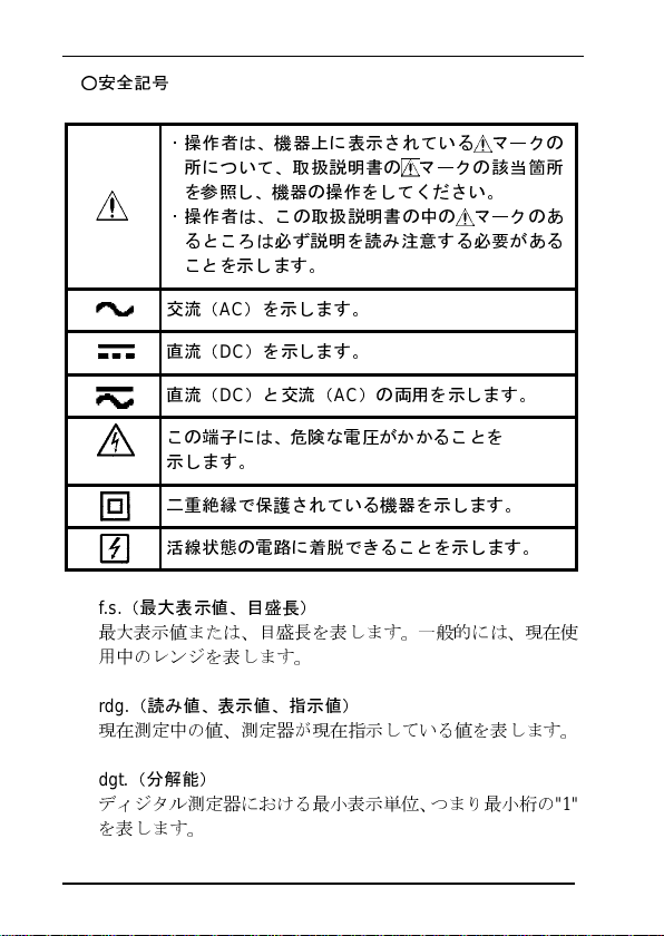
○安全記号
・操作者は、機器上に表示されている マークの
所について、取扱説明書の
を参照し、機器の操作をしてください。
・操作者は、この取扱説明書の中の
るところは必ず説明を読み注意する必要がある
ことを示します。
交流(AC)を示します。
直流(DC)を示します。
直流(DC)と交流(AC)の両用を示します。
この端子には、危険な電圧がかかることを
示します。
二重絶縁で保護されている機器を示します。
活線状態の電路に着脱できることを示します。
f.s.
(最大表示値、目盛長)
最大表示値または、目盛長を表します。一般的には、現在使
用中のレンジを表します。
マークの該当箇所
マークのあ
rdg.
(読み値、表示値、指示値)
現在測定中の値、測定器が現在指示している値を表します。
dgt.
(分解能)
ディジタル測定器における最小表示単位、つまり最小桁の
を表します。
"1"
―――――――――――――――――――――――
Page 9
――――――――――――――――――――――――――
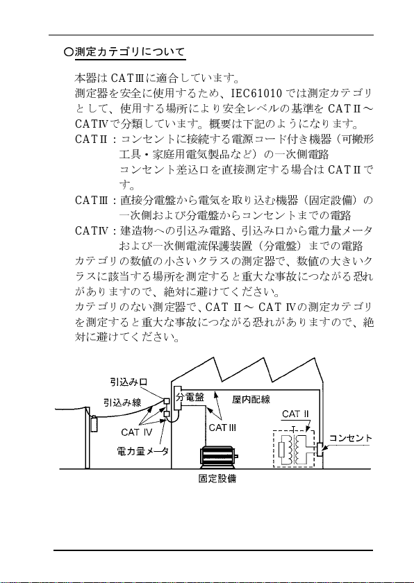
○測定カテゴリについて
本器は
CAT
Ⅲに適合しています。
測定器を安全に使用するため、
として、使用する場所により安全レベルの基準を
CAT
Ⅳで分類しています。概要 は下記 のよう になり ます。
CAT
Ⅱ:コンセントに接続する電源コード付き機器(可搬形
工具・家庭用電気製品など)の一次側電路
コンセント差込口を直接測定する場合は
す。
CAT
Ⅲ:直接分電盤から電気を取り込む機器(固定設備)の
一次側および分電盤からコンセントまでの電路
CAT
Ⅳ:建造物への引込み電路、引込み口から電力量メータ
および一次側電流保護装置(分電盤)までの電路
カテゴリの数値の小さいクラスの測定器で、数値の大きいク
ラスに該当する場所を測定すると重大な事故につながる恐れ
がありますので、絶対に避けてください。
カテゴリのない測定器で、
を測定すると重大な事故につながる恐れがありますので、絶
対に避けてください。
CAT
IEC61010
Ⅱ~
CAT
では測定カテゴリ
CAT
Ⅱ~
CAT
Ⅱで
Ⅳの測定カテゴリ
5
―――――――――――――――――――――――
Page 10
6
――――――――――――――――――――――――――
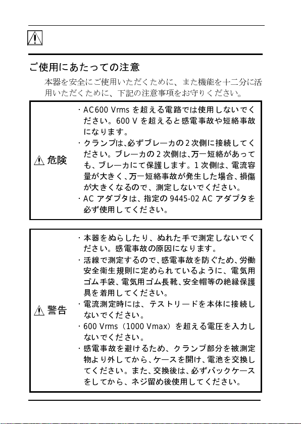
ご使用にあたっての注意
本器を安全にご使用いただくために、また機能を十二分に活
用いただくために、下記の注意事項をお守りください。
・
AC600 Vrms
ださい。
になります。
・クランプは、必ずブレーカの2次側に接続してく
危険
警告
ださい。ブレーカの2次側は、万一短絡があって
も、ブレーカにて保護します。1次側は、電流容
量
が大きく、万一短絡事故が発生した場合、損傷
が大きくなるので、測定しないでください。
・ACアダプタは、指定の
必ず使用してください。
・本器をぬらしたり、ぬれた手で測定しないでく
ださい。感電事故の原因になります。
・活線で測定するので、感電事故を防ぐため、
安全衛生規則に定められているように、電気用
ゴ
ム手袋、電気用ゴム長靴
具
を着用してください。
・電流測定時には、テストリードを本体に接続し
ないでください。
・
600 Vrms(1000 Vmax
ないでください。
・感電事故を避けるため、クランプ部分を被測定
物
より外してから、ケースを開け、電池を交換し
てください。また、交換後は、必ずバックケース
をしてから、
を超える電路では使用しないでく
600 V
を超えると感電事故や短絡事故
ネジ留め後
9445-02 AC
、安全帽等の絶縁保護
)を超える電圧を入力し
使用してください。
アダプタを
労働
―――――――――――――――――――――――
Page 11
――――――――――――――――――――――――――
7
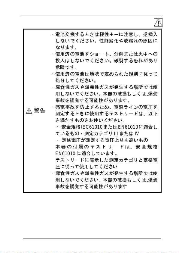
・電池交換するときは極性+-に注意し、
しないでください。性能劣化や液漏れの原因に
なります。
・使用済の電池をショート、分解または火中への
投入
はしないでください。破裂する恐れがあり
危険です。
・使用済の電池は地域で定められた規則に従って
処
分してください。
・腐食性ガスや爆発性ガスが発生する場所では使
用しないでください。本器の破損もしくは、
事故を誘発する可能性があります。
・感電事故を防止するため、電源ラインの電圧を
警告
測定するときに使用するテストリードは、以
を満たすものをお使いください。
・安全規格
ているもの・測定カテゴリ
・ 定格電圧が測定する電圧よりも高いもの
本器の付属のテストリードは、安全規格
EN61010に適
テストリードに表示した測定カテゴリと定格電
圧に従って使用してください
・腐食性ガスや爆発性ガスが発生する場所では使
用しないでください。本器の破損もしくは、
事故を誘発する可能性があります
IEC61010
または
合しています。
EN61010に適
III
または
逆挿入
爆発
下
合し
IV
爆発
―――――――――――――――――――――――
Page 12
8
――――――――――――――――――――――――――
・精密機器なのでクランプコア先端部に
挟ん
だり、コアの隙間に物を差し込んだりしな
いでください。
・本器の損傷を避けるため、運搬および取り扱い
の際は振動、衝撃を避けてください。特に、
などによる衝撃に注意してください。また、クラ
ンプセンサに不要な力を加えたり、測定箇所に
無
理にこじ入れたりしないでください。
・使用前には、保存や輸送による故障がないか、点
注意
検と動作確認をしてから使用してください。故
障を確認した場合は、お買上店(代理店)か 最
りの営業所にご連絡ください。
・本器の損傷を避けるため、最大入力範囲を超え
る電流を入力しないでください。最大入力
は、測定電流の周波数によって異なります。(第
3
章仕様図4
力すると、クランプセンサが発熱しますので注
意してください。
参照)連続して高い周波数を
異物等
を
落下
寄
範囲
入
―――――――――――――――――――――――
Page 13
――――――――――――――――――――――――――
・電池が消耗した状態(表示部の 点灯)で、使
用しないでください。必ず新しい電池と交換し
てください。
・電池交換時に、電池スナップの金具がしっかり
と接続されているか確認してください。金具に
ゆ
るみがあった場合は、金具を調整し、確実に
続
されるようにしてください。確実に接続され
ていないと、電源が入らなかったり、使用中に電
源が切
・本器の調整や修理は、危険を良く知った技能者
・内部メモリ保護のため、ACアダプタの抜差し
・ この機器は室内用に設計されています。安全性を
・直
注意
・テストリードの先端金属ピンには、取り外し可
・キャップを装着して測定する場合、キャップを
・感電事故を防ぐため、ケーブル内部から白また
れる場合があります。
の責任で行ってください。
は、電源を切った状態で行ってください。
損なわないで0℃~40℃の温度
射日光や高温、多湿、結露
の保存や使用はしないでください。変形、絶縁
化を起
こし、仕様を満足しなく
能なキャップが装着されています。
短絡
事故を防ぐため、測定カテゴリ
定するときは、必ずキャップをつけて使用して
ください。
定部に届かない場合はキャップを外して使用し
てください。
測定カテゴリについては、取扱説明書の「測定カ
テゴリについて」(5ページ)
損傷しないように注意してください。測定中に
不
用意にキャップが外れた場合などは、感電事
故を防ぐため取り扱いには十分注意してくださ
い。
は赤色部分(絶縁層)が露出していないか確認し
てください。ケーブル内部の色が露出している
場合は、使用しないでください。
CATⅡで測定するときに、ピンが被測
まで使用できます。
するような
を参照してください。
なります。
CATⅢで測
環境下
接
で
劣
9
―――――――――――――――――――――――
Page 14

10
――――――――――――――――――――――――――
注記
・トランスや大電流路など強磁界の発生
線
機など強電界の発生
ない場合があります。
・本器の汚れをとるときは、柔らかい布に水か中
含ませて、軽く拭
セトン、エーテル、ケトン、シンナー、ガソリン系を含む
剤
は絶対に使用しないでください。変形、変色することがあ
ります。
・長い間使用しないときは、電池の液漏れによる腐食を防ぐた
めに電池を抜いて保管してください。
・クランプオン
子を使用しています。ホール素子には経時的なドリフト、あ
るいは
周囲温
度によるドリフトがありますので、連続測定
には注意が必要です。
・ホール素子個々にバラツキがあ
を規定できません。連続測定時や温度変化の大きい使用
化
においては、あらかじめ無入力でゼロ点の変化を掴んでお
くことをお勧めします。なお、ゼロ点の変化は直流分です。
ACモードにおいては影響ありません。
・ホール素子固有のオフセットのため、電源投入直後に表示が
0
にならない場合がありますが故障ではありません。このカ
ウント残りは0~数A程度の個体差があります。
・DCモ
ードまたは
源投入ごとに必ず0ADJ/RESET
整を行っ
ゼロ調整後
ウント残りの影響
てください。
に表示値が0となっていれば、電源投入直後のカ
している近くでは、正確な測定ができ
いてください。ベンジン、アルコール、ア
AC/DC
ハイテスタの電流検出部にはホール
AC/DCモードでお使いいただく場合は、電
はなく測定いただけます。
している近く、また
性洗剤を少
り、経時や温度による変化量
キーを押してオート
無
量
洗
素
時
環境
ゼロ調
―――――――――――――――――――――――
Page 15
――――――――――――――――――――――――――
11
第 1 章 製品概要
1.1
製品の概要
3284
クランプオン
交
流、および、交流+直流電流を測定することができます。
ワ
ンチップマイコンの採用により多機能化がはかれ、特に
ずらわしいゼロ調整をワ
出力端子を持ち、またAC電源対応をしていますので、記
などの測定器に接続しての測定も可能です。
AC/DC
ハイテスタ は、活線状態で直流、
ンタッチで行えます。
録計
わ
―――――――――――――――――――――――
第1章 製品概要
Page 16
12
――――――――――――――――――――――――――
1.2
本器の特長
○マイコン搭載による多機能
マ
イコン搭載により機能も充実、小型、多機能で使い易くな
りました。
○真の実効値表示
真の実効値変換回
できます。
○
AC+DC
交
流に直流が重畳した波形や全波整流、
が可能です。
○ピーク測定可能
電流・電圧ともにピーク(波高値)ホールド測定ができます。
また、ピークの変動も見ることができます。
○
REC
機能
測定値の最大値、最小値などを表示することができます。
○出力端子付
出力端子に記録計やオシロスコープを接続することにより、
簡
単に電流記録および周波数記録が取れます。
電流(記録出力:
周波
数(記録出力:
○二電源方
電池とAC電源
式
路により、ひずみ波形の電流も正確に測定
測定可能
どちらでも使用できます。
化
REC,波
REC
)
形出力:
半波整
MON
流などの測定
)
―――――――――――――――――――――――
第1章 製品概要
Page 17
――――――――――――――――――――――――――
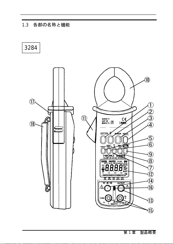
1.3
各部の名称と機能
13
3284
⑩
⑰
①
②
⑱
⑪
③
④
⑤
⑥
⑨
⑧
⑦
⑫
⑭
⑯
⑬
⑮
―――――――――――――――――――――――
第1章 製品概要
Page 18
14
――――――――――――――――――――――――――
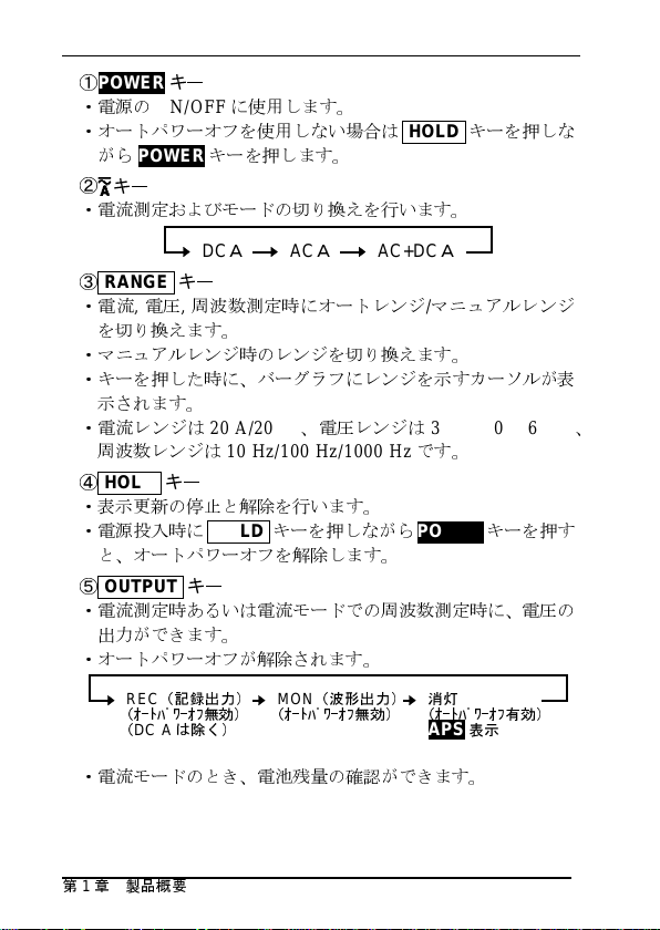
①
POWER
・電源の
・オートパワーオフを使用しない場合は
がら
②
キー
キー
ON/OFF
POWER
に使用します。
キーを押します。
HOLD
キーを押しな
・電流測定およびモードの切り換えを行います。
DC
A
AC
③
RANGE
キー
・電流,電圧,周波数測定時にオートレンジ/マニュ
A
AC+DC
A
アルレンジ
を切り換えます。
・
マニュ
アルレンジ時のレンジを切り換えます。
・キーを押した時に、バーグラフにレンジを示すカーソルが表
示されます。
・電流レンジは
周波
数レンジは
④
HOLD
20 A/200 A、電圧
10 Hz/100 Hz/1000 Hz
キー
レンジは
30 V/300 V/600 V
です。
・表示更新の停止と解除を行います。
・電源
投入時にHOLD
キーを押しながら
POWER
キーを押す
と、オートパワーオフを解除します。
⑤
OUTPUT
キー
・電流測定時あるいは電流モードでの周波数測定時に、電圧の
出力ができます。
・オートパワーオフが解除されます。
、
REC
(記録出力)
(オートパワーオフ無効)
(
DC A
は除く)
MON
(波形出力)
(オートパワーオフ無効)消灯(オートパワーオフ有効)
APS
表示
・電流モードのとき、電池残量の確認ができます。
―――――――――――――――――――――――
第1章 製品概要
Page 19
――――――――――――――――――――――――――
⑥
SLOW/PEAK/Hz
・
SLOW
・
・
・Hzは電流モード、電圧モードでの周波数測定を行います。
⑦
・電圧測定およびモードの切り換えを行います。
⑧
・レコード(
・
・
・
・オートパワーオフが解除されます。
⑨
・
・ピーク測定時にデータのリセットを行います。
・レコード(
・
⑩
は表示の更新を遅くします。(1回/3秒
FAST
は表示の更新を速くします。(4回/秒
FAST
表示はなく、単位記号が点滅します。
PEAKは波形のピ
ホ
ールド)
(
AC, AC+DCモードにて)
キー
MAX/MIN
最大値と最小値の平均値(
MAXはREC
します。
MINはREC
します。
AVEはREC
平均
値を表示します。
0ADJ/RESET
DC A, AC+ DC A, DC V時にオートゼロを行います。
ACA, AC +DCA, ACV, AC+D CVモード時、無入力で表示が
0
にならない場合、
キーを押すとゼロキャンセル補正が行えます。
クランプセンサ
電流測定をする際は、⑪レバーを握りクランプセンサの先端
を開き、被測定導体が中央部になるようにしてクランプセン
サをしっ
REC
かりと閉じます。
キー
)
)
ーク(波高値)の測定を行います。(ピーク
DCV AC+DCVACV
キー
REC
)機 能 と し て 、最 大 値(
機能をスタートさせてからの測定最大値を表示
機能をスタートさせてからの測定最小値を表示
機能をスタートさせてからの最大値と最小値の
キー
)機能動作時にデータのリセットを行います。
AVE
HOLD
キーを押した後に、
MAX),
)の表示ができます。
最小値(
0ADJ/RESET
15
MIN),
―――――――――――――――――――――――
第1章 製品概要
Page 20
16
――――――――――――――――――――――――――
⑪
レバー
クランプセンサの開閉を行う際に握ります。
⑫
表示部(
LCD
)
ADJ
HOLD
MON
REC
APS
AUTO
SLOW
REC
MAX
MIN
AVE
Hz
V
―――――――――――――――――――――――
第1章 製品概要
直流(DC)
交流(AC
交流+
オート
正
電池
データホールド
波
記録出力(DC)が
オートパワーオ
オートレンジ
表示
レコード機能
最大値
最小値
平均値=
周波
電
)
直流(
AC+DC
ゼロ調整
機能が
消耗警告
形出力(AC)が
更新約1回/3秒
数
圧
あるいはゼロキャンセル
有効
フ有効
最大値+最小値
)
有効
有効
2
補
Page 21
――――――――――――――――――――――――――
PEAK
RMS
A
hour 1
min 1
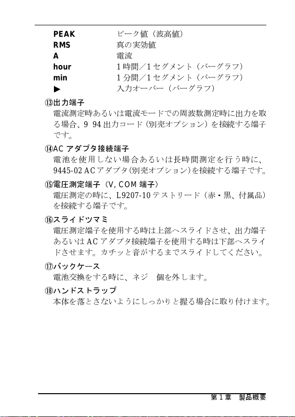
⑬
出力端子
電流測定時あるいは電流モードでの周波数測定時に出力を取
る場合、
です。
⑭ACアダプタ接続端子
電池を使用しない場合あるいは長時間測定を行う時に、
9445-02 AC
⑮
電圧測定端子(
電圧測定の時に、
を接続する端子です。
⑯
スライドツマ
電圧測定端子を使用する時は上部へスライドさせ、出力端子
あるいはACアダプタ接続端子を使用する時は下部へスライ
ドさせます。カチッと音がするまでスライドしてください。
⑰
バックケース
電池交換をする時に、ネジ2個を外
⑱
ハン
本体を落とさないようにしっかりと握る場合に取り付けます。
9094
ドストラップ
ピ
ーク値(波高値)
真の実効
電流
入
出力コード(別売オプション)を接続する端子
アダプタ(別売オプション)を接続する端子です。
V, COM
L9207-10
ミ
値
時間/1セグメント(バーグラフ)
分間/1セグ
力オーバー(バーグラフ)
端子)
メント(バーグラフ)
テストリード(赤・黒、付属品)
します。
17
―――――――――――――――――――――――
第1章 製品概要
Page 22
18
――――――――――――――――――――――――――
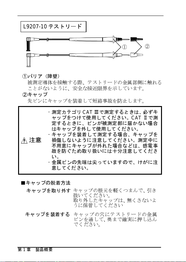
L9207-10
テストリード
①
①
バリア(障壁)
被測定導体を接触する際
ことがないように、安全な接近限界を示しています。
②
キャップ
先ピ
ンにキャップを装着して短絡事故を防止します。
・測定カテゴリ
ャップをつけて使用してください。
定するときに、ピンが被測定部に届かない場合
はキャップを外して使用してください。
・キャップを装着して測定する場合、キャップを
注意
■
キャップの脱着方法
キャップを取り外す
キャップを装着するキャ
損傷しないように注意してください。測定中に
不
用意にキャップが外れた場合などは、感電事
故を防ぐため取り扱いには十分注意してくださ
い。
・金属ピンの先端は尖っていますので、けがに注
意してください。
、テストリードの金属部側に触れる
CATⅢで測定するときは、必ずキ
キャップの根元を軽くつまんで、引き
抜
いてください。
取り外したキャップは、無くさないよ
うに保管してください
ップの穴にテストリードの金属
ピンを通
でください。
して、奥まで確実に押し込
②
CATⅡで測
ん
―――――――――――――――――――――――
第1章 製品概要
Page 23
――――――――――――――――――――――――――
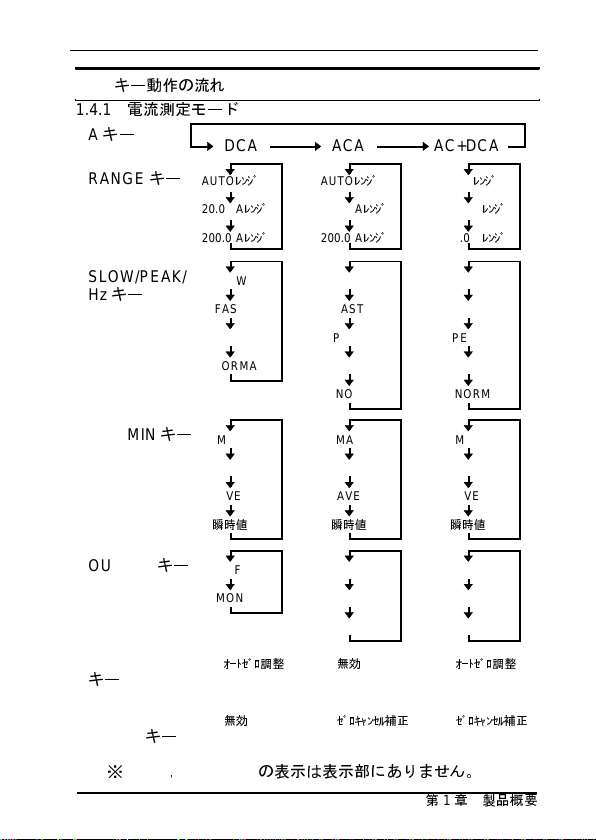
1.4
キー動作の流れ
1.4.1
電流測定モード
A
キー
RANGE
キー
DCA AC+DCAACA
AUTO
レンジ
20.00 A
レンジ
200.0 A
レンジ
AUTO
20.00 A
200.0 A
レンジ
レンジ
レンジ
AUTO
20.00 A
200.0 A
19
レンジ
レンジ
レンジ
SLOW/PEAK/
Hz
キー
MAX/MIN
OUTPUT
0ADJ/RESET
キー
キー
SLOW
FAST
PEAK
NORMAL
MAX
MIN
AVE
瞬時値
OFF
MON
オートゼロ調整 無効 オートゼロ調整
SLOW
FAST
PEAK
Hz
NORMAL
MAX
MIN
AVE
瞬時値
OFF
REC
MON
SLOW
FAST
PEAK
Hz
NORMAL
MAX
MIN
AVE
瞬時値
OFF
REC
MON
キー
HOLD+0ADJ/
RESET
キー
※
FAST,NORMAL
―――――――――――――――――――――――
無効 ゼロキャンセル補正 ゼロキャンセル補正
の表示は表示部にありません。
第1章 製品概要
Page 24
20
――――――――――――――――――――――――――
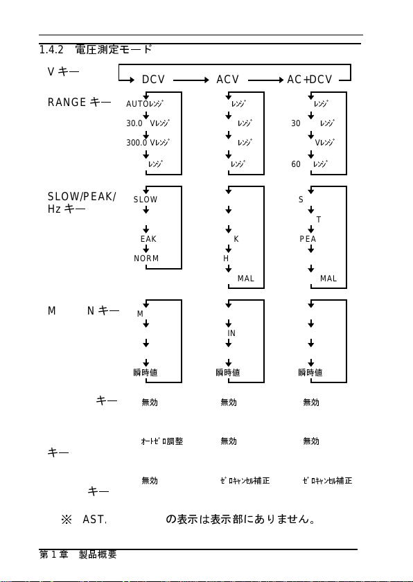
1.4.2
電圧測定モード
V
キー
RANGE
キー
DCV AC+DCVACV
AUTO
レンジ
30.00 V
レンジ
300.0 V
レンジ
600 V
レンジ
AUTO
30.00 V
300.0 V
600 V
レンジ
レンジ
レンジ
レンジ
AUTO
30.00 V
300.0 V
600 V
レンジ
レンジ
レンジ
レンジ
SLOW/PEAK/
Hz
キー
MAX/MIN
OUTPUT
0ADJ/RESET
キー
キー
SLOW
FAST
PEAK
NORMAL
MAX
MIN
AVE
瞬時値
無効 無効 無効
オートゼロ調整 無効 無効
SLOW
FAST
PEAK
Hz
NORMAL
MAX
MIN
AVE
瞬時値
SLOW
FAST
PEAK
Hz
NORMAL
MAX
MIN
AVE
瞬時値
キー
HOLD+0ADJ/
RESET
キー
※
FAST,NORMAL
―――――――――――――――――――――――
第1章 製品概要
無効 ゼロキャンセル補正 ゼロキャンセル補正
の表示は表示部にありません。
Page 25

――――――――――――――――――――――――――
1.4.3
周波数測定モード
電流(
AC A, AC+DC A)モ
電圧(
AC V, AC+DC V)モ
ード、
ード
21
SLOW/PEAK/
Hz
キー
RANGE
MAX/MIN
OUTPUT
キー
キー
キー
0ADJ/RESET
キー
SLOW PEAKFAST
Hz NORMAL
電流モード 電圧モード
AUTO
レンジ
10.00 Hz
レンジ
100.0 Hz
レンジ
1000 Hz
レンジ
MAX
MIN
AVE
瞬時値
OFF
REC
無効 無効
AUTO
10.00 Hz
100.0 Hz
1000 Hz
MAX
MIN
AVE
瞬時値
無効
レンジ
レンジ
レンジ
レンジ
―――――――――――――――――――――――
第1章 製品概要
Page 26
22
――――――――――――――――――――――――――
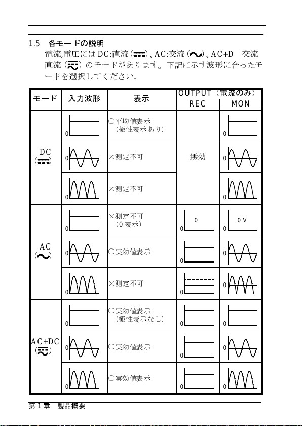
1.5
各モードの説明
電流,電圧には
直流(
DC:
直流( )、
AC:交流( )、
AC+DC:交流
)のモードがあります。下記に示す波形に合った
モ
ードを選択してください。
モード入力波
0
形
○平均値表示
(極性表示あり)
表示
OUTPUT
(電流のみ)
REC MON
0
+
DC
AC
)
)
)
0
0
0
0
0
0
0
0
(
(
AC+DC
(
―――――――――――――――――――――――
第1章 製品概要
×測定不可
×測定不可
×測定不可
(0表示)
○実効値表示
×測定不可
○実効値表示
(極性表示なし)
○実効値表示
○実効値表示
無効
0V
0
0
0
0 0
0
0 0
0
0
0V
0
0
0
0
Page 27
――――――――――――――――――――――――――
23
第 2 章 測定方法
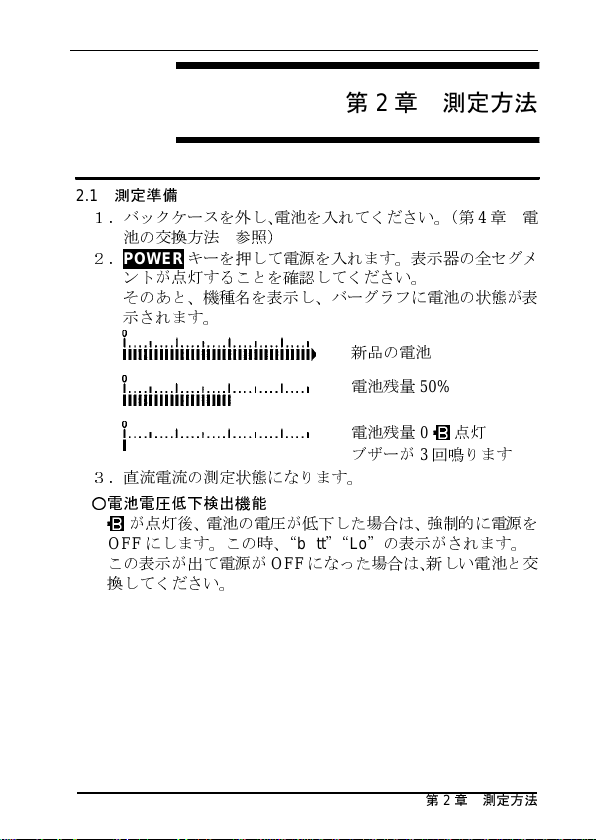
2.1
測定準備
1.バックケースを外し、電池を入れてください。(第4章電
池の交換方法 参照)
2.
POWER
ントが点灯することを確認してください。
そのあと、機種名を表示し、バーグラフに電池の状態が表
示されます。
キーを押して電源を入れます。表示器の全セグメ
新
品の電池
電池残量
電池残量0点
ブザーが3回鳴ります
3.直流電流の測定状態になります。
○電池電圧低下検出機能
が点灯後、電池の電圧が低下した場合は、強制的に電源を
OFF
にします。この時、“
この表示が出て電源が
換してください。
bAtt”“Lo
OFF
になった場合は、新しい電池と交
―――――――――――――――――――――――
50%
灯
”の表示がされます。
第2章 測定方法
Page 28
24
――――――――――――――――――――――――――
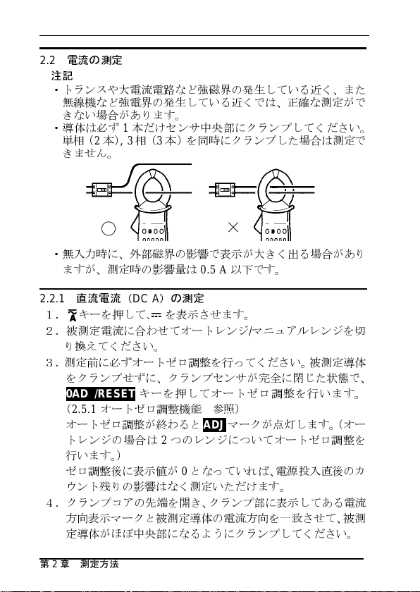
2.2
電流の測定
注記
・トランスや大電流電路など強磁界の発生している近く、また
無線機など強電界の発生している近くでは、正確な測定がで
きない場合があります。
・導体は必ず1本だけセンサ中央部にクランプしてください。
単相(2本),3相(3本)を同時にクランプした場合は測定で
きません。
〇
・無入力時に、外部磁界の影響で表示が大きく出る場合があり
ますが、測定時の影響量は
2.2.1
直流電流(
1.
キーを押して、 を表示させます。
2.被測定電流に合わせてオートレンジ/マニュアルレンジを切
り換えてください。
3.測定前に必ずオートゼロ調整を行ってください。被測定導体
をクランプせずに、クランプセンサが完全に閉じた状態で、
0ADJ/RESET
(
2.5.1
オートゼロ調整が終わると
トレンジの場合は2つのレンジについてオートゼロ調整を
行います。)
ゼロ調整後に表示値が0となっていれば、電源投入直後のカ
ウント残りの影響はなく測定いただけます。
4.クランプコアの先端を開き、クランプ部に表示してある電流
方向表示マークと被測定導体の電流方向を一致させて、被測
定導体がほぼ中央部になるようにクランプしてください。
―――――――――――――――――――――――
第2章 測定方法
DC A
)の測定
キーを押してオートゼロ調整を行います。
オートゼロ調整機能 参照)
×
0.5 A
以下です。
ADJ
マークが点灯します。(オー
Page 29
――――――――――――――――――――――――――
被測定導体
電流方向
電流方向マーク
×悪い
25
注記
・
DCA
モードでは、交流分を含まない直流電流のみ正確な測定
が行えます。(
・
20 A
レンジでは、最大
は1A~
20 A
1.5
各モードの説明 参照)
25 A
まで表示しますが確度保証範囲
までです。
・各レンジとも、レンジの1%(確度保証外)以下では内部補正
演算により、大きな誤差となる可能性があります。
・電源投入時に値がゼロにならない場合がありますが、不具合
ではありません。測定前に必ずオートゼロ調整を実行してく
ださい。
2.2.2
交流電流(
キーを押して、~を表示させます。
1.
AC A
)の測定
2.必要に応じてオートレンジ/マニュアルレンジを切り換えて
ください。
3.クランプコアの先端を開き、被測定導体がほぼ中央部になる
ようにクランプしてください。
注記
・入力がなくなった直後や無入力でのモード切換えにより、し
ばらく表示が0にならない場合がありますが(約10秒程度)、
内部回路の都合によるもので、異常ではありません。0になら
ないうちに測定しても、測定値に影響はありません。
・測定環境温度により、無入力でも表示が0にならない場合が
ありますので、ゼロキャンセル補正を行ってください。(
2.5.2
ゼロキャンセル補正機能 参照)
・測定の応答速度は、フルスケール(
(0%→
90%
)は約
250 ms
ms
です。(
2.2.5の図1, 2
、立下り(
参照)
―――――――――――――――――――――――
f.s.
)入力時に、立上り
100%→10%
)は約
第2章 測定方法
500
Page 30
26
――――――――――――――――――――――――――
・
ACA
モードでは、直流,全波整流,半波整流波形,および直流
交流波形の測定は行えません。(
・
20 A
レンジでは、最大
囲は1A~
・各レンジとも、レンジの1%(確度保証外)以下では内部補正
演算により、大きな誤差となる可能性があります。
2.2.3
1.
2.必要に応じてオートレンジ/マニュアルレンジを切り換えて
ください。
3.測定前に必ずオートゼロ調整を行ってください。被測定導体
をクランプせずに、クランプセンサが完全に閉じた状態で、
0ADJ/RESET
(
2.5.1
オートゼロ調整が終わると
トレンジの場合は2つのレンジについてオートゼロ調整を行
います。)
ゼロ調整後に表示値が0となっていれば、電源投入直後のカ
ウント残りの影響はなく測定いただけます。
4.表示が0にならない場合は、
0ADJ/RESET
ださい。
5.クランプコアの先端を開き、被測定導体がほぼ中央部になる
ようにクランプしてください。
注記
・入力がなくなった直後や無入力でのモード切換えにより、し
ばらく表示が0にならない場合がありますが(約10秒程度)、
内部回路の都合によるもので、異常ではありません。0になら
ないうちに測定しても、測定値に影響はありません。
・測定環境温度により、無入力でも表示が0にならない場合が
ありますので、ゼロキャンセル補正を行ってください。(
ゼロキャンセル補正機能 参照)
・DC測定を行った場合、極性は表示されません。また、クラン
プセンサの向きを変えると値が変わる場合がありますが、い
ずれも確度範囲内です。(被測定電路が直流成分のみの場合
は、
―――――――――――――――――――――――
第2章 測定方法
20 A
交流+直流電流(
キーを押して、 を表示させます。
キーを押してオートゼロ調整を行います。
オートゼロ調整機能 参照)
キーを押してゼロキャンセル補正を行ってく
DCA
モードで測定することをお勧めします。)
25 A
までです。
AC+DC A
1.5
各モードの説明 参照)
まで表示しますが、確度保証範
)の測定
ADJ
マークが点灯します。(オー
HOLD
キーを押した後、
2.5.2
+
Page 31

――――――――――――――――――――――――――
・測定の応答速度は、フルスケール(
(0%→
90%
)は約
250 ms
、立下り(
ms
です。(
2.2.5の図1, 2
・
20 A
レンジでは、最大
囲は1A~
・各レンジとも、レンジの1%(確度保証外)以下では内部補正
演算により、大きな誤差となる可能性があります。
・オートゼロ調整後に周波数出力をした場合、電流測定は、オ
ートゼロ調整が無効になります。周波数出力を解除(
すると、オートゼロ調整が有効な電流測定を行います。
・電源投入時に値がゼロにならない場合がありますが、不具合
ではありません。測定前に必ずオートゼロ調整を実行してく
ださい。
2.2.4
1.
2.
DCA, AC+D CA
ートゼロ調整を行ってください。(
3.
SLOW/PEAK/Hz
りますので
20 A
までです。
ピークホールド測定
キーを押して、測定電路に応じて測定モードを選択します。
モードの場合は
参照)
PEAK
参照)
25 A
キーを押すと以下のように表示が切り換
に設定してください。
f.s.
)入力時に、立上り
100%→10%
まで表示しますが、確度保証範
0ADJ/RESET
2.5.1
オートゼロ調整機能
)は約
キーによりオ
27
500
OFF
)
SLOW PEAKFAST
(単位記号点滅)
4.必要に応じてオートレンジ/マニュアルレンジを切り換え
てください。(ピーク電流値の予測が付かない場合は
A
レンジに固定してください。)
5.測定前に
てください。
6.クランプコアの先端を開き、被測定導体がほぼ中央部にな
るようにクランプしてください。
注記
・ピーク測定を行った場合、極性は表示されません。また、ク
ランプセンサの向きを変えると値が変わる場合がありますが、
いずれも確度範囲内です。
0ADJ/RESET
キーを押してデータをリセットし
―――――――――――――――――――――――
Hz
(DC除く)
NORMAL
200
第2章 測定方法
Page 32

28
――――――――――――――――――――――――――
・約
1ms
・クランプ後にも、必要に応じて
・ピーク測定モードで、無入力時に
・ホールド値は大きな値が入らない限り変化しませんが、オー
・オートパワーオフ時間を超える測定には、
・ピーク測定値は出力できません。ピーク測定モードで
・ピーク値の変動を見る場合は、
以上の幅を持つパルスからとらえることができます。
ータをリセットしてください。
データをリセットしても表示が0にならない場合は、クラン
プセンサの帯磁が考えられますので、一度ピークモードから
抜けて、
0ADJ/RESET
ら、再度設定してください。(
数カウント数字が残る場合もあります)
トパワーオフでデータが消えてしまわないように注意してく
ださい。(
てください。
OUTPUT
時値(表示なし)にしてください。
2.9
オートパワーオフ機能 参照)
キーを押した場合は、現在の測定値を出力します。
0ADJ/RESET
0ADJ/RESET
キーによりオートゼロ調整を行ってか
0ADJ/RESET
MAX/MIN
キーを押してデ
キーを押して
キーを押しても、
REC
機能を使用し
キーを押して、
瞬
MAX AVEMIN
2.2.5
出力機能
電流レンジのフルスケール「2000」カウントに対して
AC/DC1V
REC
(
DCA
1.
2.
―――――――――――――――――――――――
第2章 測定方法
の出力が得られます。
(記録出力)と
モードでは
RANGE
OUTPUT
し、出力が有効になりオートパワーオフは自動的に無効に
なります。(
キーを押して電流レンジを固定してください。
キーを押すと
MON
MON
APS消灯)
(波形出力)が選択できます。
のみ、
1.5
REC
瞬時値
(表示なし)
各モードの説明 参照)
または
MON
マークが点灯
Page 33

――――――――――――――――――――――――――
3.
OUTPUT
REC
(オートパワーオフ無効)
4.本器の測定レンジと
キー を押すと、出力を切り換えることができます。
(記録出力)
MON
(波形出力)
(オートパワーオフ無効)消灯(オートパワーオフ有効)
記録計
などの測定器のレンジの双方か
29
ら設定レンジを決めてください。換算表を示します。
測定器レンジ /DIV 10 mV 20 mV 50 mV 0.1 V 0.2 V 0.5 V 1V
200 Aレンジ 2A 4A 10 A 20 A 40 A 100 A 200 A
20 Aレンジ 0.2 A 0.4 A 1A 2A 4A 10 A 20 A
※ 数値は記録計など測定器の
出力端子を短絡したり、電圧を加えると故障の原因
警告
になりますので注意してください。
1DIV
当たりの電流値
注記
・出力機能を使うときは、必ず
または
MON
い。REC、MONが消
マークが点灯していることを確認してくださ
灯している状態でも出力していますが、
OUTPUT
キーを押して
REC
オートパワーオフが有効になっていますので、約10分後に電
源が
OFF
になってしまいます。また、
DCA
モードで
MON
ークが消灯している場合は、マイナスの電流値でもプラス
に出力されますので特に
・オートレンジ(
AUTO
は、押したときの電流レンジに固定されます。(
・
DCA
モードでオートゼロ調整を行わないと、出力値に誤差が
ご注意
)のまま
ください。
OUTPUT
キーを押した場合
AUTO消灯)
生じます。
・ゼロキャンセル補正機能は、出力には無効ですので、測定環
境温度で無入力時に、電圧を出力してしまうことがあります。
・
REC
出力はアナログ出力です。
は立上がり(0%→
約
500ms)で違
いがあります。(図
90%約250 ms
f.s.
入力時の出力応答時
)と立下がり(
2, 3
参照)また、測定値
100%→10%
がレンジに対して小さいほど応答時間が長くなります。
・電流測定出力を取りながら表示更新の変更,
ピーク測定,周
波数測定,レコード機能,データホールド機能の使用も可能
です。(モードの変更,
レンジの変更,
電圧測定モードへの変
更,オートゼロ調整機能は出力が変動してしまいます。)
―――――――――――――――――――――――
第2章 測定方法
マ
側
間
Page 34

30
k
――――――――――――――――――――――――――
・
記録計との接続は、9094
出力コード(別売)を使用してくだ
さい。
・
記録計
の入力インピーダンスは1MΩ
以上のものを使用してく
ださい。インピーダンスが低いと表示値にも影響を与えます。
・周波数測定記録を取りながら
キーを押した場合には、出力
は周波数記録になっています。電流出力を取る場合は、
OUTPUT
キーを押して一旦解除してから再設定する必要が
あります。
・長時間の記録には、
9445-02 ACアダ
プタ(別売)を使用して
ください。
・ACアダプタを使用した場合、商用電源におおきな
含まれていると、数カウントの表示が出たり、出力に
が乗る場合があります。このときは、
いは
記録計側のL端子
GAIN [dB]
2
AC+DC A (MON)
0
-2
-4
-6
-8
-10
-12
-16
-18
100m 1 10 100 1k 10k 100
AC A (MON)
をアースに接続してください。
FREQUENCY [Hz]
記録計の接地端子
ノイズ
ノイズ
が
ある
図1 電流出力周波数特性
―――――――――――――――――――――――
第2章 測定方法
Page 35

――――――――――――――――――――――――――
出力波形入力波形
20 A
10 A
250 ms
31
図2出力応答波形(立上り)
出力波形入力波形
500 ms
図3出力応答波形(立下り)
―――――――――――――――――――――――
第2章 測定方法
Page 36

32
――――――――――――――――――――――――――
2.3
電圧の測定
2.3.1
直流電圧(
1. キーを押して、 を表示させます。
2.スライドツマミを使用してスライドカバーを開いてから、
赤色テ
ドを電圧測定端子の
3.必要に応じてオートレンジ/マニュアルレンジを切り換え
てください。
4.表示が0になっていない場合は使用するレンジに切り替え
て(マニュアルレンジ)、
トゼロ調整を行います。ゼロ調整が終わると
点灯します。(
5.測定カテゴリに応じてキャップを着脱してください。
6.十分に気を付けて、テストリードをそれぞれ電路
せてください。
注記
・測定カテゴリ
て使用してください。
定部に届かない場合はキャップを外して使用してください。
・オートゼロ調整範囲は、レンジの4%までです。
・オートゼロ調整を行ったレンジから他のレンジに変更すると、
調整値がずれてしまい正確な測定ができません。変更後は必
ずオートゼロ調整を行ってください。(オートレンジではオ
ートゼロ調整を行わないでください。)
・"-"マークが点灯した場合は、
赤色テ
す
。
・
DCV
モードでは、交流分を含まない直流電圧のみ正確な測定
が行えます。(
・各レンジで最大
100%
までです。
・各レンジとも、レンジの1%(確度保証外)以下では内部補正
演算により、大きな誤差となる可能性があります。
DC V
)の測定
ストリードを電圧測定端子のVに、
CATⅢで測定するときは、必ずキャップをつけ
ストリード側の電位より高くなっていることを示しま
COM
に差し込んでください。
0ADJ/RESET
2.5.1
オートゼロ調整機能 参照)
CATⅡで測定するときに、ピンが被測
黒色テ
1.5
各モードの説明 参照)
125%
まで表示しますが、確度保証は
黒色テ
ストリー
キーを押してオー
ADJ
マークが
へ接触
ストリード側の電位が
10%
さ
~
―――――――――――――――――――――――
第2章 測定方法
Page 37

――――――――――――――――――――――――――
2.3.2
交流電圧(
1. キーを押して、~を表示させます。
2.スライドツマミを使用してスライドカバーを開いてから、
赤色テ
ドを電圧測定端子の
3.必要に応じてオートレンジ/マニュアルレンジを切り換え
てください。
4.測定カテゴリに応じてキャップを着脱してください。
5.十分に気を付けて、テストリードをそれぞれ電路
せてください。
注記
・測定カテゴリ
て使用してください。
定部に届かない場合はキャップを外して使用してください。
・入力がなくなった直後や無入力でのモード切換えにより、し
ばらく表示が0にならない場合がありますが(約10秒程度)、
内部回路の都合によるもので、異常ではありません。0になら
ないうちに測定しても、測定値に影響はありません。
・測定環境温度により無入力で表示が0にならない場合は、
HOLD
キャンセル補正を行ってください。(
正機能 参照)
・測定の応答速度は、フルスケール(
(0%→
ms
です。(
・
ACV
モードでは直流,全波整流,半波整流波形,および直流
交流波形の測定は行えません。(
・各レンジで最大
100%
・各レンジとも、レンジの1%(確度保証外)以下では内部補正
演算により、大きな誤差となる可能性があります。
AC V
)の測定
ストリードを電圧測定端子のVに、
COM
に差し込んでください。
CATⅢで測定するときは、必ずキャップをつけ
CATⅡで測定するときに、ピンが被測
キーを押した後に
90%
)は約
250 ms
2.2.5の図1, 2
125%
までです。
0ADJ/RESET
、立下り(
参照)
まで表示しますが、確度保証は
2.5.2
f.s.
)入力時に、立上り
100%→10%
1.5
各モードの説明 参照)
黒色テ
キーを押してゼロ
ゼロキャンセル補
)は約
33
ストリー
へ接触
500
10%
さ
+
~
―――――――――――――――――――――――
第2章 測定方法
Page 38

34
――――――――――――――――――――――――――
2.3.3
交流+直流電圧(
1. キーを押して、 を表示させます。
2.スライドツマミを使用してスライドカバーを開いてから、
赤色テ
ストリードを電圧測定端子のVに、
ドを電圧測定端子の
3.必要に応じてオートレンジ/マニュアルレンジを切り換え
てください。
4.表示が安定しても表示が0にならない場合は使用するレン
ジに切り替えて(マニュアルレンジ)、
た後に
0ADJ/RESET
行ってください。(
5.測定カテゴリに応じてキャップを着脱してください。
6.十分に気を付けて、テストリードをそれぞれ電路
せてください。
注記
・測定カテゴリ
て使用してください。
定部に届かない場合はキャップを外して使用してください。
・ゼロキャンセル補正を行ったレンジから他のレンジに変更する
と、補正値がずれてしまい正確な測定ができません。(オート
レンジではゼロキャンセル補正を行わないでください。)
オートレンジで行ってしまった場合は、一度電源を切り再び電
源を入れてから、再度ゼロキャンセル補正を行ってください。
・入力がなくなった直後や無入力でのモード切換えにより、し
ばらく表示が0にならない場合がありますが(約10秒程度)、
内部回路の都合によるもので、異常ではありません。0になら
ないうちに測定しても、測定値に影響はありません。
・DC測定を行った場合、極性は表示されません。また、テスト
リードの接続を変えると値が変わる場合がありますが、いず
れも確度範囲内です。(被測定電路が直流成分のみの場合は
DCV
モードで測定することをお勧めします。)
・測定の応答速度は、フルスケール(
(0%→
90%
ms
・
各レンジで最大
100%
・各レンジとも、レンジの1%(確度保証外)以下では内部補正
演算により、大きな誤差となる可能性があります。
)は約
です。(
までです。
AC+DC V
2.5.2
CATⅢで測定するときは、必ずキャップをつけ
250 ms
2.2.5の図1, 2
125%
)の測定
黒色テ
COM
に差し込んでください。
キーを押してゼロキャンセル補正を
ゼロキャンセル補正機能 参照)
CATⅡで測定するときに、ピンが被測
、立下り(
参照)
まで表示しますが、確度保証は
HOLD
f.s.
)入力時に、立上り
100%→10%
ストリー
キーを押し
へ接触
)は約
10%
さ
500
~
―――――――――――――――――――――――
第2章 測定方法
Page 39

――――――――――――――――――――――――――
2.3.4
ピークホールド測定
1. キーを押して、測定電路に応じて測定モードを選択しま
す。
2.スライドツマミを使用してスライドカバーを開いてから、
赤色テ
ストリードを電圧測定端子のVに、
ドを電圧測定端子の
3.
SLOW/PEAK/Hz
換わりますので
COM
に差し込んでください。
キーを押すと以下のように表示が切り
PEAK
に設定してください。
黒色テ
35
ストリー
SLOW PEAKFAST
(単位記号点滅)
4.必要に応じてオートレンジ/マニュアルレンジを切り換え
てください。(ピーク電圧値の予測が付かない場合は
V
レンジに固定してください。)
5.測定カテゴリに応じてキャップを着脱してください。
6.十分に気を付けて、テストリードをそれぞれ電路
せてください。
7
.測定前に
てください。
注記
・測定カテゴリ
て使用してください。
定部に届かない場合はキャップを外して使用してください。
・ピーク測定を行った場合、極性は表示されません。また、
ストリードの接続を変えると値が変わる場合がありますが、
いずれも確度範囲内です。
・約
1ms
・ピーク値の変動を見る場合は
値(表示なし)にしてください。
・ピーク測定モードでは、ゼロ調整は無効です。
0ADJ/RESET
CATⅢで測定するときは、必ずキャップをつけ
以上の幅を持つパルスからとらえることができます。
MAX AVEMIN
キーを押してデータをリセットし
CATⅡで測定するときに、ピンが被測
MAX/MIN
―――――――――――――――――――――――
Hz
(DC除く)
キーを押して、瞬時
瞬時値
(表示なし)
NORMAL
600
へ接触
第2章 測定方法
さ
テ
Page 40

36
――――――――――――――――――――――――――
2.4
周波数測定
2.4.1
電流モードでの周波数測定
1. キーを押して、被測定電路に合わせACあるいは
の位置にします。
2.被測定電路の電流値がわかっている場合は電流のレンジを
マニュアルレンジに固定してください。(電流値が不明の
場合、測定してからレンジを固定してください。)
3.
SLOW/PEAK/Hz
換わりますのでHzに設定してください。(単
点滅します。バーグラフには電流値が表示されます。)
キーを押すと以下のように表示が切り
AC+DC
位記号のA
が
SLOW PEAKFAST
(単位記号点滅)
4.必要に応じてオートレンジ/マニュアルレンジを切り換え
てください。
5.クランプコアの先端を開き、被測定導体がほぼ中央部にな
るようにクランプしてください。
注記
・
100 Hz、1000 Hz
----
になります。
・
1Hz未満は表示が
・
1kHz
・入力値がレンジ値に対して小さい場合は、表示が
・
・
・インバータのように特殊波形の電路の周波数に対しては、
・全波整流の場合、内部回路でAC結
・周波数レンジあるいは入力周波数によっては、測定周波数表
―――――――――――――――――――――――
第2章 測定方法
以上は
示あるいは表示のふらつきなど、正確な測定ができない場合
があります。
10 Hz
レンジまたは
しますが、確度保証は
MAX/MIN
易配慮
がなされていますが、測定できない場合もあります。
(キャリア周波数が数
周波数を表示します。
示が安定するまでに時間を要する場合があります。
レンジでは、
----
になります。
O.L.
表示となります。
100 H z
キーを押しても出力値に影響はありません。
kHz
10 Hz未満の入力では表示が
レンジでは、最大
10%~100%
と低い場合など
Hz RMS
----やO.L.
125%
までです。
)
合していますので2倍
まで表示
表
簡
の
Page 41

――――――――――――――――――――――――――
2.4.2
電圧モードでの周波数測定
1. キーを押して、被測定電路に合わせACあるいは
の位置にします。
2.被測定電路の電圧値がわかっている場合は、電圧のレンジ
をマニュアルレンジに固定してください。(電圧値が不明
の場合、測定してからレンジを固定してください。)
3.スライドツマミを使用してスライドカバーを開いてから、
赤色テ
ストリードを電圧測定端子のVに、
ドを電圧測定端子の
4.
SLOW/PEAK/Hz
換わりますのでHzに設定してください。(単
点滅します。バーグラフに電圧値が表示されます。)
COM
に差し込んでください。
キーを押すと以下のように表示が切り
黒色テ
位記号のV
37
AC+DC
ストリー
が
SLOW PEAKFAST
(単位記号点滅)
5.必要に応じてオートレンジ/マニュアルレンジを切り換え
てください。
6.測定カテゴリに応じてキャップを着脱してください。
7.十分に気
せてください。
注記
・測定カテゴリ
て使用してください。
定部に届かない場合はキャップを外して使用してください。
・
100 Hz、1000 Hz
----
になります。
・
1Hz未満は表示が
・
1kHz
・入力値がレンジ値に対して小さい場合は表示が
示あるいは表示のふらつきなど、正確な測定ができない場合
があります。
・
10 Hz
しますが、確度保証は
・イン
易配慮
(キャリア周波数が数
を付けて、テストリードをそれぞれ電路
CATⅢで測定するときは、必ずキャップをつけ
CATⅡで測定するときに、ピンが被測
レンジでは、
----
以上は
レンジまたは
バータのように特殊波形の電路の周波数に対しては、
がなされていますが、測定できない場合もあります。
になります。
O.L.
表示となります。
100 H z
10%~100%
kHz
10 Hz未満の入力では表示が
レンジでは、最大
と低い場合など)
―――――――――――――――――――――――
Hz NORMAL
125%
までです。
第2章 測定方法
へ接触
----やO.L.
まで表示
さ
表
簡
Page 42

38
――――――――――――――――――――――――――
・全波整流の場合、内部回路でAC結
合していますので2倍
の
周波数を表示します。
・周波数レンジあるいは入力周波数によっては、測定周波数表
示が安定するまでに時間を要する場合があります。
2.4.3
出力機能
周波数測定出力は、電流測定モードでのみ可能です。
周波数レンジのフルスケール「1000」カウントに対して
DC1V
の出力が得られます。出力は表示更新と同じ2回/秒に
なります。(
D/A
出力のため急激な周波数変動の場合は出力
波形は階段状になります。)
1.電流モードでの周波数測定を参照して設定を行ってください。
2.
OUTPUT
キーを押すと
REC
マークが点灯し、出力が有
効になります。
3.オートパワーオフは自動的に無効になります。(
4.本器の測定レンジと
記録計
などの測定器のレンジの双方か
APS消灯)
ら設定レンジを決めてください。
測定器レンジ /DIV 10 mV 20 mV 50 mV 0.1 V 0.2 V 0.5 V 1V
1000 Hzレンジ 10 Hz 20 Hz 50 Hz 100 Hz 200 Hz 500 Hz 1000 Hz
100 Hzレンジ 1Hz 2Hz 5Hz 10 Hz 20 Hz 50 Hz 100 Hz
10 Hzレンジ 0.1 Hz 0.2 Hz 0.5 Hz 1Hz 2Hz 5Hz 10 Hz
注記
※ 数値は記録計など測定器の
・出力機能を使うときは、必ず
OUTPUT
1DIV
当たりの周波数値
キーを押して
REC
マークが点灯していることを確認してください。RECが消
灯している状態での出力は、電流値の出力になっています。
・
AC+DCA
・オートレンジ(
押したときの周波数レンジに固定されます。(
・
HOLD
・
----
モードでは、オートゼロ調整は無効です。
AUTO
)のまま
OUTPUT
キーを押すと、出力値もホールドされます。
表示の場合は0V、
O.L.
表示の場合は、
キーを押した場合は、
AUTO消灯)
1.36 V
程度出力し
ます。
・
記録計との接続は、9094
出力コード(別売)を使用してくだ
さい。
・
記録計
の入力インピーダンスは1MΩ
以上のものを使用して
ください。
―――――――――――――――――――――――
第2章 測定方法
Page 43

――――――――――――――――――――――――――
39
・長時間の記録には、
ください。
・ACアダプタを使用した場合、商用電源におおきな
含まれていると、数カウントの表示が出たり、出力に
が乗る場合があります。このときは、
いは
記録計側のL端子
・電流測定記録を取りながら周波数測定モードに入った場合に
は、出力は電流記録になっています。周波数出力を取る場合
は、
OUTPUT
設定してください。
2.5
オートゼロ調整/ゼロキャンセル補正機能
2.5.1
オートゼロ調整機能
DC A, AC+ DC A, DC V
ンサの帯磁分や温度特性による内部回路のオフセット分を
動
で調整する機能です。直流の大電流を測定したり、強力な
磁力を近づけた場合、コアの帯磁があります。
1.無入力状態で表示が安定したのを確認してから
キーを押してください。
注記
・電流モードでの調整範囲は、±4.5 A
・入力している状態や表示値が減少している過程で行うと正常な
オートゼロ調整ができなくなり測定に影響が出ます。再度、無
入力であることを確認して表示が安定してから行ってください。
・
AC+DC A
(20秒程度)
・
AC+DCA
かわらず表示が0にならない場合はゼロキャンセル補正機能
を使用してください。
・オートゼロ調整中に、再度
トゼロ調整が無効になります。
・
DC V
でください。必ず使用するレンジ(マニュアルレンジ)にし
てから行ってください。
モードでは表示が安定するのに時間がかかります。
モードで正常にオートゼロ調整が行われたにもか
モードではオートレンジでオートゼロ調整を行わない
―――――――――――――――――――――――
9445-02 ACアダ
をアースに接続してください。
キーを押して一旦電流出力を解除してから再
モードで測定する際に、クランプセ
ADJ
0ADJ/RESET
プタ(別売)を使用して
記録計の接地端子
0ADJ/RESET
マークが点灯します。
です。
キーを押すと、オー
第2章 測定方法
ノイズ
ノイズ
ある
が
自
Page 44

40
――――――――――――――――――――――――――
2.5.2
ゼロキャンセル補正機能
ACA, AC +DCA, ACV, AC+D CV
らず表示が0にならない場合に使用できる機能です。
1.
HOLD
キーを押してください。
2.
0ADJ/RESET
注記
・オートレンジではゼロキャンセル補正は行わないでください。
必ず使用するレンジ(マニュアルレンジ)にしてから行って
ください。
・入力があったり表示値が減少している過程で行うと、測定値
が正常より低くなり、測定値に影響が出ます。
・表示が0の時には
キーは効きません。
・
AC+DCA
いと
HOLD
・ゼロキャンセル補正機能は、表示のみに機能するため、出力
値の補正は行っていません。
2.6
データホールド機能
表示を止めて読み取りたいときに使用します。
1.
HOLD
ディジタル表示とバーグラフ表示を保持します。
データホールド機能はすべての測定で使用できます。
データホールド機能を解除するには、もう一度
を押してください。ホールド中に
ーグラフに現在のレンジを表示します。
キーを押してください。
HOLD
モ ード のとき、先にオートゼ ロ調整が終わって いな
キーを押した後の
キーを押してください。
モードで無入力にもかかわ
HOLD
マークが表示されます。
ADJ
キーを押した後の
0ADJ/RESET
HOLD
HOLD
RANGE
マークが点滅します。
0ADJ/RESET
キーは効きません。
マークが表示され
キー
HOLD
キーを押すと、バ
2.7
表示更新の変更
起動
時のディジタル表示更新は約2回/秒です。測定状況に応
じて、表示更新を変更することができます。
SLOW/PEAK/Hz
わります。
SLOW PEAKFAST
(単位記号点滅)
―――――――――――――――――――――――
第2章 測定方法
キーを押すと以下のように表示が切り換
Hz
(DC除く)
NORMAL
Page 45

――――――――――――――――――――――――――
2.7.1 SLOW
電流測定時,電圧測定時に表示値が変動して読みにくい場合、
表示更新を遅くして(約1回/3秒)読み取
できます。
2.7.2 FAST
・電流測定時,電圧測定時にディジタル表示更新を約4回/秒に
します。起動電流の測定など応用範囲が広がります
・AあるいはVという単
・起動電流測定の際はレコード機能(
(
MAX
2.8
レコード機能
レコード機能を使うと、測定値の最大,最小,最大と最小の
平均
1.測定表示値
電流または電圧を測定している時に
とレコード機能が動作します。
ーが押された時点からの最大値(
均値(AVE
能が動作している状態で、
ように表示が切り換わります。
い場合は瞬時値を表示しています。
モード
りやすくすることが
モード
位記号が点滅
)を保持すると読み取りに便利です。
REC
を保持します。
)を本機の内部メモリに保持します。レコード機
MAX/MIN
します。
REC)を使
MAX/MIN
RECが点滅し、MAX/MIN
MAX
)・最小値(
キーを押すと、下記の
MAX,MIN,AVE
って最大値
キーを押す
の表示がな
41
。
MIN)・平
キ
MAX→MIN→AVE
表示を切り換えている間、データ(
されますが、最大,最小のデータ更新があった場合、データ
値は変化します。
レコード機能動作中はオートパワーオフは解除されます。
(
APS消灯)
平均値(AVE
した値を表示します。
SLOW/PEAK/Hz
レコード機能を動作させて,瞬時値(表示なし)にするとピ
ークの変動を見ることができます。
)は、平均値=((最大値+最小値)/2)で計算
キーにより、
―――――――――――――――――――――――
→瞬時値
(表示なし)
MAX, MIN, AVE
PEAK
モードにした後に
第2章 測定方法
)は保持
Page 46

42
――――――――――――――――――――――――――
2.経過時間の表示
MAX/MIN
グラフのセグメントが点滅して、経過時間が表示されます。
バーグラフの右隅に
フの1セグメントが1分間を表します。
1分経過するご
滅
から点灯に変わります。バーグラフがすべて点灯したとき
は経過時間が30分です。経過時間が30分以上になると、
分経過するごとにバーグラフが左から1セグメントずつ点
から消灯に変わります。
点滅セグメントの左側が点灯しているとき
点灯しているセグメントの数が経過時間(0~29)
図は20分経過したことを表しています。
キーを押してレコード機能を動作させると、バー
min
が表示されているときは、バーグラ
とにバーグラフが左から1セグメントずつ点
:
滅
1
点滅セグメントの右側が点灯してるとき
消
灯してるセグメントの数(
図は50分経過した
MAX/MIN
ら瞬時値に切り換わるときに、バーグラフの右隅が
ります。このときは、バーグラフの1セグメントが1時間を
表します。バーグラフの読み方は
がすべて点灯したときは経過時間が29時間です。
図は1時間40分経過
―――――――――――――――――――――――
第2章 測定方法
ことを表しています。
キーを押してディジタル表示が平均値(
+30)が経過時間(30~59
したことを表しています。
:
min
と同じで、バーグラフ
AVE
hour
)
)か
にな
Page 47

――――――――――――――――――――――――――
3.レコード機能の停止
HOLD
キーを押すと、レコード機能が停止します。
点灯し、
す。レコード機能が停止している間は、導体からクランプセ
ンサをはずしてもデータは更新されません。
が再開し、
4.レコード機能のリセット
レコード機能動作中にデータをリセットする場合は、
0ADJ/RESET
5.レコード機能の解除
レコード機能を解除するには、電流測定中では
圧測定中では
レコード機能を解除すると、オートパワーオフ機能が有効に
なります。(
注記
・測定時間が長くなる場合は、
使用
フにて電池残量を確認してから測定を開始することをお勧め
します。
・オートレンジでレコード機能を開始したときは、
キーを押したときのレンジに固定されます。
・最小値データ
ド機能を開始するようにしてください。無入力時に開始する
と最小値は常にゼロのままになってしまいます。また、レコ
ード機能を終了する場合は、
タ、平均値データを読み取ってから測定を終了してください。
レコード機能を終了しないまま、被測定電路からクランプを
はずしたりテストリードをはずすと最小値はゼロになってし
まいます。
・電源をオフにするとデータは消えてしまいます。
RECが点滅
HOLD
キーをもう一度押すと、
RECも点滅
キーを押してください。
APS
するか、電流モードで
,平均
から点灯に変わり、経過時間も停止しま
HOLDが消
します。
キーを押してください。
点灯)
9445-02 ACアダ
OUTPUT
値データが必要な場合は測定中にレコー
HOLD
えレコード機能
プタ(別売)を
キーを押してバーグラ
キーを押し最小値デー
43
HOLD
キーを、電
MAX/MIN
が
―――――――――――――――――――――――
第2章 測定方法
Page 48

44
――――――――――――――――――――――――――
2.9
オートパワーオフ機能
・
APS
が表示されているときは、オートパワーオフ機能が有効
です。
・何もキーが押されないと約10分後に電源がオフになります。
・オフする直前に
秒間)
・
POWER
○オートパワーオフ機能を無効にする方法
・
HOLD
れる。
・
MAX/MIN
・電流モードで
2.10
電池消耗警告
・電池が消耗しています。製品の確度保証ができませんので新
しい電池に交換してください。
・電池残量のチェックは、電源投入直後および電流モードで
OUTPUT
できます。ただし、残量は目安程度ですので出力を長時
ったり
REC
い。
・電池には、しばらく使用しないと電圧値が多少上がる特性が
あります。前回警告マークが付いて終了していても、時間を
置
くと一時的には警告マークが点灯しなくなる場合もありま
すが早めに電池を交換するようにしてください。(第4章電
池の交換 参照)
APSが点滅しブザー音で警告
キー以外のキーを押すと10分
キーを押しながら
キーを押して、レコード(
OUTPUT
キーを押したときにバーグラフで確認することが
機能を使用する場合は十分に気を付けてくださ
APS
POWER
キーを押す。
キーを押して電源を入
します。(約
間延長
できます。
REC
)機能を使う。
30
間取
2.11
ブザー音
ブザー音
POWER
―――――――――――――――――――――――
第2章 測定方法
をオフするには、
キーを押して電源を入れます。
RANGE
キーを押しながら
Page 49

――――――――――――――――――――――――――
45
第 3 章 仕様
3.1
測定仕様
確度保証温湿度範囲:23℃±5℃、80%rh
確度保証期間:1
3.1.1
電流測定仕様
こと)、
年間(センサ開閉回数:1万回まで)
マークが点灯していないこと
○電流表示確度
①直流電流A(平均値表示
)
レンジ(確度範囲) 分解能 DC
20A(±1.00~±20.00A) 0.01A ±1.3%rdg.±3dgt.
200A(±10.0~±200.0A) 0.1A ±1.3%rdg.±3dgt.
以下(結露しない
②交流電流
Arms(
真の実効値表示
)
レンジ(確度範囲) 分解能 45~66Hz 10~45,66~2kHz
20A(1.00~20.00A) 0.01A ±1.3%rdg.±3dgt. ±2.0%rdg.±5dgt.
(10.0~100.0A)
200A
(100.0~200.0A)
*
レンジ(確度範囲) 分解能 10~45,66~1kHz 1kHz~2kHz
200A(100.0~200.0A)
③交流+直流電流
0.1A ±1.3%rdg.±3dgt.
0.1A ±2.0%rdg.±5dgt. ±4.0%rdg.±5dgt.
Arms(
真の実効値表示
±2.0%rdg.±5dgt.
*
)
レンジ(確度範囲) 分解能 DC,45~66Hz 10~45,66~2kHz
20A(1.00~20.00A) 0.01A ±1.3%rdg.±13dgt. ±2.0%rdg.±7dgt.
(10.0~100.0A)
200A
(100.0~200.0A)
*
レンジ(確度範囲) 分解能 10~45,66~1kHz 1kHz~2kHz
200A(100.0~200.0A)
±1.3%rdg.±13dgt.
0.1A
0.1A ±2.0%rdg.±7dgt. ±4.0%rdg.±7dgt.
―――――――――――――――――――――――
±2.0%rdg.±7dgt.
*
第3章仕様
Page 50

46
)
――――――――――――――――――――――――――
○出力確度
①直流電流A(平均値表示
)
レンジ(確度範囲) MON DC
20A(±1.00~±20.00A) 1V/f.s. ±1.3%rdg.±5mV
200A(±10.0~±200.0A) 1V/f.s. ±1.3%rdg.±5mV
②交流電流
Arms(
真の実効値表示
)
MON
レンジ(確度範囲) MON 45~66Hz 10~45,66~2kHz
20A(1.00~20.00A) AC1V/f.s. ±1.3%rdg.±5mV ±2.0%rdg.±5mV
200A
*
(10.0~100.0A)
(100.0~200.0A)
AC1V/f.s. ±1.3%rdg.±5mV
±2.0%rdg.±5mV
*
レンジ(確度範囲) MON 10~45,66~1kHz 1kHz~2kHz
200A(100.0~200.0A)
AC1V/f.s. ±2.0%rdg.±5mV ±4.0%rdg.±5mV
周波数帯域
:0.5~20kHz(±
3dB
REC
レンジ(確度範囲) REC 45~66Hz 10~45,66~2kHz
20A(1.00~20.00A) DC1V/f.s. ±1.3%rdg.±10mV ±2.0%rdg.±10mV
200A
*
(10.0~100.0A)
(100.0~200.0A)
DC1V/f.s. ±1.3%rdg.±10mV
±2.0%rdg.±10mV
*
レンジ(確度範囲) REC 10~45,66~1kHz 1kHz~2kHz
200A(100.0~200.0A)
出力応答(
③交流+直流電流
DC1V/f.s. ±2.0%rdg.±10mV ±4.0%rdg.±10mV
f.s.
入力時)
:
立上がり応答時間(0%→
立下がり応答時間(
Arms(
真の実効値表示
100%→10%)500 ms
)
90%)250 ms
以下
以下
MON
レンジ(確度範囲) MON DC,45~66Hz 10~45,66~2kHz
20A(1.00~20.00A) 1V/f.s. ±1.3%rdg.±5mV ±2.0%rdg.±5mV
(10.0~100.0A)
200A
(100.0~200.0A)
―――――――――――――――――――――――
第3章仕様
1V/f.s. ±1.3%rdg.±5mV
±2.0%rdg.±5mV
*
Page 51

――――――――――――――――――――――――――
)
*
47
レンジ(確度範囲) MON 10~45,66~1kHz 1kHz~2kHz
200A(100.0~200.0A)
1V/f.s. ±2.0%rdg.±5mV ±4.0%rdg.±5mV
周波数帯域
:DC~20kHz(±
3dB
REC
レンジ(確度範囲) REC DC,45~66Hz 10~45,66~2kHz
20A(1.00~20.00A) DC1V/f.s. ±1.3%rdg.±10mV ±2.0%rdg.±10mV
200A
*
(10.0~100.0A)
(100.0~200.0A)
DC1V/f.s. ±1.3%rdg.±10mV
±2.0%rdg.±10mV
*
レンジ(確度範囲) REC 10~45,66~1kHz 1kHz~2kHz
200A(100.0~200.0A)
出力応答(
DC1V/f.s. ±2.0%rdg.±10mV ±4.0%rdg.±10mV
f.s.
入力時)
:
立上がり応答時間(0%→
立下がり応答時間(
100%→10%)500 ms
90%)250 ms
以下
以下
○ピーク測定確度(ピークホールド機能
)
正弦波連続入力時
①直流電流
Apeak(
波高値表示
)
レンジ(確度範囲) 分解能 DC
20A(1.0~50.0A) 0.1A ±1.3%rdg.±7dgt.
200A(10.0~300.0A) 0.1A ±1.3%rdg.±7dgt.
②交流電流
Apeak(
波高値表示
)
レンジ(確度範囲) 分解能 45~66Hz 10~45,66~2kHz
20A(1.0~50.0A) 0.1A ±1.3%rdg.±7dgt. ±2.0%rdg.±7dgt.
200A
*
(10.0~142.0A)
(142.0~300.0A)
0.1A ±1.3%rdg.±7dgt.
±2.0%rdg.±7dgt.
*
レンジ(確度範囲) 分解能 10~45,66~1kHz 1kHz~2kHz
200A(142.0~300.0A)
―――――――――――――――――――――――
0.1A ±2.0%rdg.±7dgt. ±5.0%rdg.±7dgt.
第3章仕様
Page 52

48
――――――――――――――――――――――――――
③交流+直流電流
Apeak(
波高値表示
)
レンジ(確度範囲) 分解能 DC,45~66Hz 10~45,66~2kHz
20A(1.0~50.0A) 0.1A ±1.3%rdg.±7dgt. ±2.0%rdg.±7dgt.
200A
*
(10.0~142.0A)
(142.0~300.0A)
0.1A ±1.3%rdg.±7dgt.
±2.0%rdg.±13dgt.
*
レンジ(確度範囲) 分解能 10~45,66~1kHz 1kHz~2kHz
200A(142.0~300.0A)
±2.0%rdg.±13dgt. ±5.0%rdg.±13dgt.
0.1A
○周波数測定
Hz
表示確度
レンジ(確度範囲) 分解能
10Hz(1.00~10.00Hz)
100Hz(10.0~100.0Hz)
1000Hz(100~1000Hz)
0.01Hz ±0.3%rdg.±1dgt.
0.1Hz ±0.3%rdg.±1dgt.
1Hz ±1.0%rdg.±1dgt.
出力確度
レンジ(確度範囲) REC
10Hz(1.00~10.00Hz)
100Hz(10.0~100.0Hz)
1000Hz(100~1000Hz)
出力応答
:1000Hz,100Hz
DC1V/f.s. ±1.3%rdg.±3mV
DC1V/f.s. ±1.3%rdg.±3mV
DC1V/f.s. ±2.0%rdg.±3mV
レンジ4秒以下、
10Hz
レンジ6秒以下
電流共通仕様
最大許容電流
200 Arms
連続、
300 Amax.
周波数によるディレーティング特性参照
(図4)
導体位置の影響
±
0.5%
以内(センサ中心部を基準として
いかなる位置においても)
外部磁界の影響
AC400 A/m
の外部磁界において
0.5 A
相
当以下
対地間最大定格電圧
―――――――――――――――――――――――
第3章仕様
最大
AC600 Vr m s
Page 53

――――――――――――――――――――――――――
49
図4 周波数によるディレーティング特性
3.1.2
電圧測定仕様
○電圧表示確度
①直流電圧V(平均値表示
)
レンジ(確度範囲) 分解能 DC
30V(±3.00~±30.00V) 0.01V ±1.0%rdg.±3dgt.
300V(±30.0~±300.0V) 0.1V ±1.0%rdg.±3dgt.
600V(±60~±600V) 1V ±1.0%rdg.±3dgt.
②交流電圧
Vrms(
真の実効値表示
)
レンジ(確度範囲) 分解能 45~66Hz 10~45,66~1kHz
30V(3.00~30.00V) 0.01V ±1.0%rdg.±3dgt. ±1.5%rdg.±5dgt.
300V(30.0~300.0V) 0.1V ±1.0%rdg.±3dgt. ±1.5%rdg.±5dgt.
600V(60~600V) 1V ±1.0%rdg.±3dgt. ±1.5%rdg.±5dgt.
③交流+直流電圧
Vrms(
真の実効値表示
)
レンジ(確度範囲) 分解能 DC,45~66Hz 10~45,66~1kHz
30V(3.00~30.00V) 0.01V ±1.0%rdg.±13dgt. ±1.5%rdg.±13dgt.
300V(30.0~300.0V) 0.1V ±1.0%rdg.±7dgt. ±1.5%rdg.±7dgt.
600V(60~600V) 1V ±1.0%rdg.±7dgt. ±1.5%rdg.±7dgt.
―――――――――――――――――――――――
第3章仕様
Page 54

50
――――――――――――――――――――――――――
○ピーク測定確度(ピークホールド機能)
正弦波連続入力時
①直流電圧
Vpeak(
波高値表示
)
レンジ(確度範囲) 分解能 DC
30V(3.0~75.0V) 0.1V ±1.0%rdg.±7dgt.
300V(30~750V) 1V ±1.0%rdg.±7dgt.
600V(60~1000V) 1V ±1.0%rdg.±7dgt.
②交流電圧
Vpeak(
波高値表示
)
レンジ(確度範囲) 分解能 45~66Hz 10~45,66~1kHz
30V(3.0~75.0V) 0.1V ±1.0%rdg.±7dgt. ±1.5%rdg.±7dgt.
300V(30~750V) 1V ±1.0%rdg.±7dgt. ±1.5%rdg.±7dgt.
600V(60~1000V) 1V ±1.0%rdg.±7dgt. ±1.5%rdg.±7dgt.
③交流+直流電圧
Vpeak(
波高値表示
)
レンジ(確度範囲) 分解能 DC,45~66Hz 10~45,66~1kHz
30V(3.0~75.0V) 0.1V ±1.0%rdg.±7dgt. ±1.5%rdg.±7dgt.
300V(30~750V) 1V ±1.0%rdg.±7dgt. ±1.5%rdg.±7dgt.
600V(60~1000V) 1V ±1.0%rdg.±7dgt. ±1.5%rdg.±7dgt.
○周波数測定
Hz
表示確度
レンジ(確度範囲) 分解能
10Hz(1.00~10.00Hz)
100Hz(10.0~100.0Hz)
1000Hz(100~1000Hz)
3.2
一般仕様
0.01Hz ±0.3%rdg.±1dgt.
0.1Hz ±0.3%rdg.±1dgt.
1Hz ±1.0%rdg.±1dgt.
○付属機能
オ-トゼロ調整機能
ゼロキャンセル機能
DC A, AC+ DC A
0ADJ/RESET
AC
および
ーを押した後、
で
キーによりワンタッチ
AC+DC
モードで
0ADJ/RESET
HOLD
キーにより
キ
ワンタッチ
―――――――――――――――――――――――
第3章仕様
Page 55

――――――――――――――――――――――――――
レコード
データホールド
オートパワーオフ
ブザー音
電流、電圧、周波数の測定において最大値
(
MAX
)、最小値(
を表示可能
表示を保持
10.5分±1
延長、解除可能
ON/OFF
MIN
)、平均値(
分、直前にブザー音にて警告、
51
AVE
)
○表示
ディジタル表示
バーグラフ表示
オーバーレンジ表示
電池消耗警告
データホールド表示
オートパワーオフ有
効表示
単位
ゼロサプレス
表示更新レート
バーグラフ表示
表示応答時間
(レンジ固定
0%→100%
レンジ切換え
出力インピーダンス
)
―――――――――――――――――――――――
液晶表示
最大
2500
ただし
最大
ただし
最大
ただし
35
O.L.
HOLD
APS
A, V, Hz
5
カウント
ディジタル表示
NORMAL
SLOW
FAST
約4回/秒
電流、電圧1秒以下
周波数
オートレンジ/マニュアルレンジ(レンジ
固定)選択可能
300
カウント(電流)
200A
3750
1250
セグメント
表示
(点灯時、確度保証不可)
Ω以下
レンジは
カウント(電圧)
600V
レンジは
カウント(周波数)
1000Hz
バーグラフ表示
約2回/秒
約1回/3秒
約4回/秒
1000Hz, 1 00Hz
下、
10Hz
レンジは
レンジ
2000
750
1000
レンジ1秒以
2.5
カウント
カウント
カウント
秒以下
第3章仕様
Page 56

52
――――――――――――――――――――――――――
2.5
以下(
200A
回路ダイナミック
(クレストファクタ)
耐電圧
伝導性無線周波電磁
界の影響(3Vにて)
使用場所
適合規格 安全性
EMC
防塵防水性
測定可能導体径
使用温湿度範囲
温度特性
保存温度範囲
電源
最大消費電力
電池寿命
外形寸法
質量
付属品
オプション
製品保証期間
600V
レンジは
ケース-入力端子間、ケースークランプ
コア間
AC5400 Vrms/ 1
電流測定
高度
2000 m
屋内
EN61010
測定カテゴリⅢ(予想される過渡過電圧
6000 V
)汚染度
EN61326
EN61000-3-2
EN61000-3-3
EN60529 IP40
φ
33 m m
0~40℃、80%rh
0~40
℃において、
-10~50
℃(結露しないこと)
6F22(006P)9V 1
または
9445-02 AC
110 mVA
約25時間(連続、無負荷)
約
62W×230H×39D mm
約
460 g
L9207-10
9399
携帯用ケース
ハンドストラップ
電池
6F22(006P) 1
取扱説明書
9445-02 AC
9094
出力コード
1
年間
レンジは
1.7
-0.3 A
以下
まで
2
以下
以下(結露しないこと)
テストリード(赤黒)
1
アダプタ
1.5
以下)
0.1
アダプタ(別売)
1
1
以下、
分間
×確度仕様/℃
本
1
―――――――――――――――――――――――
第3章仕様
Page 57

――――――――――――――――――――――――――
53
第 4 章 電池の交換方法
バックケースの留めネジは強く締めすぎないでく
注意
ださい。
1.バックケースの留めネジ2本を、プラスドライバで外しま
す。
2.バックケースを外します。
3.電池スナップのコードを引っ張らないように電池を外しま
す。
4.電池スナップに電池を確実に取り付けます。
5.バックケースをネジ留めします。
0.5N・m
程度が適切です。
―――――――――――――――――――――――
第4章 電池の交換方法
Page 58

54
――――――――――――――――――――――――――
―――――――――――――――――――――――
第4章 電池の交換方法
Page 59

――――――――――――――――――――――――――
55
第 5 章
AC アダプタ(別売)の使用
9445-02 AC
で挿入します。
注記
・電池は入れてあっても外してあっても構いません。
・電池を入れてある場合、停電などによりAC電源が取れなく
ても、電池によりバックアップされ引き続き測定が行えます。
・電池駆動からACアダプタ駆動へ切り換わる場合(停電から
の復帰など)下記について影響があります。
①電流測定時の
に戻ります。
DC A
AC+DC A
ます。
②周波数測定時の
元に戻ります。
③ピークホールド測定→大きく変動したままそのまま値をホ
ールドしてしまいます。
いずれも電池の電圧がACアダプタの電圧値(
より低くなるほど、影響が大きくなります。
短
おくことをお勧めします。
・新品電池を入れた場合に、ACアダプタによる電圧値よりも
電池の電圧値が高いときは電池が消耗します。電池の電圧の
方
が低くなるとACアダプタに切り換わります。
・ACアダプタ使用時の電池残量表示(バーグラフ)はACアダ
プタの電圧値から算出して表示していますので、電池の
表示ではありません。
―――――――――――――――――――――――
アダプタ(別売)をACアダプタ接続端子の奥ま
MON
出力波形→
測定で長時間記録を取り、停電が考えられる場合は
モードで
時間での停電復帰が考えられる場合は新品電池を入れて
REC
REC
10msec
程度変動した後、元
出力を使用することをお勧めし
出力波形→
第5章ACアダプタ(別売)の使用
10msec
程度変動した後、
typ.9V
残量
)
Page 60

56
――――――――――――――――――――――――――
―――――――――――――――――――――――
第5章ACアダプタ(別売)の使用
Page 61

――――――――――――――――――――――――――
57
第 6 章
ハンドストラップの付け方
ハンドストラップを付けると操作性が増します。
―――――――――――――――――――――――
第6章 ハンドストラップの付け方
Page 62

58
――――――――――――――――――――――――――
―――――――――――――――――――――――
第6章 ハンドストラップの付け方
Page 63

――――――――――――――――――――――――――
59
第 7 章
故障とお考えになる前に
次
のような場合は、故障とお考えになりがちですが、他に
因
があることがあります。修理を依頼される前にもう一度お
確かめください。
症状 電池 電池スナップ テストリード
電源が入らない
の点灯後、す
電源がオフする
が点灯する
使用中に電源が
オフする
電圧測定ができ
ない
処
置:
直らないときは、
修理をご依頼
ださい。
ぐ
*
く
○ ○
○
○
○ ○
新
しい電池と
交
換する
電池スナップ
の端子部接
チェック
テストリード
触
の断線チェッ
ク
○
原
注記
*
APS
(オートパワーオフ)が有効になっているとき、何も
キーが押されないと、約10分後に電源がオフになります。
(「2.9
電源投入後、表示が
です。
―――――――――――――――――――――――
オートパワーオフ機能」参照)
E.001~E.005
になる場合は修理が
第7章 故障とお考えになる前に
必要
Page 64

60
――――――――――――――――――――――――――
○電源が入らない
・電池使用時には電池が消耗していないか確認してください。
(
2.1
測定準備参照)
・ACアダプタ使用時にはACアダプタ接続端子あるいはコン
セントの奥まで挿入されているか確認してください。
・電池では電源が入るのにACアダプタでは入らない場合は
AC
アダプタの不具合が考えられます。(ACアダプタは
9445-02 AC
○表示が0にならない
・
DC A, AC+ DC A, DC V
整機
・
AC A, AC V, AC+DC V
ル
補正機
・
AC+DC A
ならない場合は、ゼロキャンセル補正を行ってください。
アダプタを使用してください)
モードの場合は
能を使用してください。
モードの場合は
能を使用してください。
モードでオート
ゼロ調整
2.5.1
オート
ゼロ調
2.5.2ゼロキャンセ
を行っても、表示が0に
―――――――――――――――――――――――
第7章 故障とお考えになる前に
Page 65

――――――――――――――――――――――――――
○表示値が予測よりも小さい
電流測定
・クランプセンサがしっかりと閉じているか確認してくださ
い。
・被測定電路の周波数が製品仕様の範囲から外れていないか
確認してください。(インバータのキャリア周波数が高いと
低めの表示になります)
・
2.5.1
オート
オート
ゼロ調整機
ゼロ調整機
機
能の使用方法が間違っていないか確認してください。
・使用すべきモードが間違っていないか確認してください。
(
1.5各モードの説明 参照)
・ピーク値が製品仕様の回路ダイナミックを超えてしまって
いないか確認してください。
(ピーク値の変動は
の注記を参照してください)
・クレストファクタ(=ピーク値/実効
路
ダイナミックを超えてしまっていないか確認してくださ
い。
・電池消耗警告マークが点灯していないか確認してください。
電圧測定
・テストリードがしっかりと接続されて いるか 確認してくだ
さい。
・被測定電路の周
確認してください。
・
2.5.1
機
能の使用方法が間違っていないか確認してください。
・使用すべきモードが間違っていないか確認してください。
(
1.5各モードの説明 参照)
・ピーク値が製品仕様の回路ダイナミックを超えてしまって
いないか確認してください。
(ピーク値の変動は
の注記を参照してください)
・クレストファクタ(=ピーク値/実効
イナミックを超えてしまっていないか確認してください。
・電池消耗警告マークが点灯していないか確認してください。
周波数測定
・インバータなど特殊波形は測定できない場合もあります の
で波形を確認してください。
・入力値がレンジに対して
能および
2.2.4
あるいは
波数が製品仕様の範囲から外れていないか
能および
2.2.4
あるいは
10%以上
2.5.2ゼロキャンセル
2.3.4
ピークホールド測定
値) が製品仕様の中の回
2.5.2ゼロキャンセル
2.3.4
ピークホールド測定
値) が製品仕様の回路ダ
あるか確認してください。
61
補正
補正
―――――――――――――――――――――――
第7章 故障とお考えになる前に
Page 66

62
――――――――――――――――――――――――――
○表示値が予測よりも大きい
電流測定
・レンジがあっているか確認してください。
・予想している周波数成分以外が含まれていないか出力機能
の
MON
で波形を確認してください。
・ピーク測定時に
確認してください。
・近くに大きな磁界や電界やノイズが発生していないか確
してください。
・ピーク電流測定中に、電池駆動からACアダプタ駆動に切り
換わった場合(停電から復帰の場合など)、表示値が大きくな
る場合があります。(第5章AC
参照)
電圧測定
・レンジがあっているか確認してください。
・ピーク測定時に
確認してください。
・近くに大きな磁界や電界やノイズが発生していないか確
してください。
周波数測定
・近くに大きな磁界や電界やノイズが発生していないか確
してください。
・インバータなど特殊波形は測定できない場合もあります の
で波形を確認してください。
0ADJ/RESET
0ADJ/RESET
キーで表示をリセットしたか
認
アダプタ(別売)の使用
キーで表示をリセットしたか
認
認
―――――――――――――――――――――――
第7章 故障とお考えになる前に
Page 67

――――――――――――――――――――――――――
○出力値が予測よりも小さい
・表示値と同様の確認をしてください。
・
9094
出力コードが断線していないか確認してください。
, MON
・出力の選択(
ださい。
・先に選択されたモード(電流か周波数)の出力になっていな
いか確認してください。
・接続する測定器の入力インピーダンスが1MΩ以上あるか、
確認してください。
・接続する測定器がAC結合になっていないかあるいはフィル
タ機能がONになっていないか確認してください。
○出力値が予測よりも大きい
・表示値と同様の確認をしてください。
・出力の選択(
ださい。
・先に選択されたモード(電流か周波数)の出力になっていな
いか)
・電流測定時の
に、電池駆動からACアダプタ駆動に切り換わった場合(停
電から復帰の場合など)、出力値が大きく変動する場合があ
ります。(第5章AC
○表示値がふらつく
・被測定電路が安定しているか確認してください。
・電圧測定の場合はテストリードがしっ かりと 接続さ れて い
るか、断線がないか確認してください。
・周波数測定の場合、インバータなど特殊波形は測定できない
場合もありますので波形を確認してください。
REC
REC
MON
)が間違っていないか確認してく
, MON
)が間違っていないか確認してく
出力および周波数測定時の
アダプタ(別売)の使用 参照)
REC
63
出力中
―――――――――――――――――――――――
第7章 故障とお考えになる前に
Page 68

64
――――――――――――――――――――――――――
―――――――――――――――――――――――
第7章 故障とお考えになる前に
Page 69

――――――――――――――――――――――――――
65
第 8 章 アフターサービス
・補修部品の最低保有期間は、
・アフターサービスについてご不明な点は、お
か、最寄りの
・輸送の際は、破損しないように梱包し、故障内容も書き添え
てください。輸送中の破損については保証しかねます。
営業所にご連絡
製造打ち
ください。
切り後5年間です。
買上店(代理店
)
―――――――――――――――――――――――
第8章 アフターサービス
Page 70

66
――――――――――――――――――――――――――
―――――――――――――――――――――――
第8章 アフターサービス
Page 71

3284
Page 72

Page 73

3284
CLAMP ON
AC/DC HiTESTER
INSTRUCTION MANUAL
Page 74

Page 75

Contents
Introduction i
Shipping Check
Safety
Attentions During Use
ⅸ
ii
iii
Chapter 1 Product Outline
1.1 Product Outline 1
1.2 Features
1.3 Parts and Functions
1.4 Flowchart of Key Operations
1.4.1 Current Measurements Mode 10
1.4.2 Voltage Measurements Mode
1.4.3 Frequency Measurements Mode
10
1.5 Modes 13
Chapter 2 Measurement Procedure 15
2.1 Preparations 15
2.2 Current Measurement
2.2.1 Measuring DC Current (DC A) 16
2.2.2 Measuring AC Current (AC A)
2.2.3 Measuring AC/DC Current (AC+DC A)
2.2.4 Peak Hold Measurement
2.2.5 Output Function
2.3 Voltage Measurement 25
2.3.1 Measuring DC Voltage (DC V) 25
2.3.2 Measuring AC Voltage (AC V)
2.3.3 Measuring AC/DC Voltage (AC+DC V)
2.3.4 Peak Hold Measurement
16
1
2
3
11
12
17
18
20
21
26
27
28
Page 76

2.4 Frequency Measurement 30
2.4.1 Frequency Measurement in Current Mode 30
2.4.2 Frequency Measurement in Voltage Mode
2.4.3 Output Function For Frequency
31
32
2.5 Auto-Zero-Adjustment/Zero-Cancel
Correction Function
2.5.1 Auto-Zero-Adjustment Function 34
2.5.2 Zero-Cancel Correction Function
34
35
2.6 Data Hold Function HOLD 35
2.7 Alteration of Counter Updates
2.7.1 SLOW mode 36
2.7.2 FAST mode
36
36
2.8 Recording Function REC 36
2.9 Auto Power-Off Function APS
2.10 Battery Low Warning
41
2.11 Beep Tone
40
41
Chapter 3 Specifications 43
3.1 Measurement Specifications 43
3.1.1 Current Measurement Specifications 43
3.1.2 Voltage Measurement Specifications
48
3.2 General Specifications 50
Chapter 4 Battery Replacement 53
Chapter 5 AC Adapter (Optional)
Chapter 6 Attaching The Hand Strap
Chapter 7 Troubleshooting
Chapter 8 Service
55
57
59
65
Page 77

―――――――――――――――――――――――――――
Introduction
Thank you for purchasing the HIOKI "3284 CLAMP
ON AC/DC HiTESTER". To obtain maximum
performance from the instrument/ device/ product,
please read this manual first, and keep it handy for
future reference.
Request
We have tried to bring this manual as close to
perfection as we could achieve. If perchance you
find any unclear portions, mistakes, omissions, or
the like, we would be most obliged if you could
please notify us of them via any HIOKI agent, or
directly.
i
――――――――――――――――――――――――
Introduction
Page 78

ii
―――――――――――――――――――――――――――
Shipping Check
When the unit is delivered, check and make sure
that it has not been damaged in transit. In
particular, check the accessories, panel switches,
keys, and terminals.
If the unit is damaged, or fails to operate according
to the specifications, contact your dealer or HIOKI
representative.
Check the 3284 Unit and the Supplied
Accessories
Main unit
3284 CLAMP ON AC/DC HiTESTER
Supplied accessories
9399 CARRYING CASE 1
L9207-10 TEST LEAD (red and black) 1
Hand Strap 1
6F22 (006P) 1
Instruction manual 1
Options
9094 OUTPUT CORD
9445-02 AC ADAPTER
9445-03 AC ADAPTER (EU)
――――――――――――――――――――――――
Shipping Check
Page 79

―――――――――――――――――――――――――――
iii
Safety
DANGER
This instrument is designed to comply with IEC
61010 Safety Standards, and has been
thoroughly tested for safety prior to shipment.
However, mishandling during use could result in
injury or death, as well as damage to the
instrument. Be certain that you understand the
instructions and precautions in the manual
before use. We disclaim any responsibility for
accidents or injuries not resulting directly from
instrument defects.
This Instruction Manual provides information and
warnings essential for operating this unit in a safe
manner and for maintaining it in safe operating
condition. Before using this unit, be sure to
carefully read the following safety notes.
――――――――――――――――――――――――
Safety
Page 80

iv
―――――――――――――――――――――――――――
The following symbols in this manual indicate the
relative importance of cautions and warnings.
Indicates that incorrect operation
DANGER
presents an extreme hazard that could
result in serious injury or death to the
user.
Indicates that incorrect operation
WARNING
presents a significant hazard that could
result in serious injury or death to the
user.
Indicates that incorrect operation
CAUTION
presents a possibility of injury to the user
or damage to the instrument.
Indicates advisory items related to
NOTE
performance or correct operation of the
instrument.
――――――――――――――――――――――――
Safety
Page 81

―――――――――――――――――――――――――――
Safety Symbols
The symbol printed on the instrument
indicates that the user should refer to a
corresponding topic in the manual (marked
with the
relevant function.
In the manual, the
particularly important information that the
user should read before using the instrument.
Indicates AC (Alternating Current).
Indicates DC (Direct Current).
Indicates both DC (Direct Current) and AC
(Alternating Current).
Indicates that dangerous voltage may be
present at this terminal
Indicates a device which is doubleinsulated.
Indicates that the instrument may be connected
to or disconnected from a live circuit.
f.s. (maximum display or scale value, or length of scale)
Signifies the maximum display (scale) value or the
length of the scale (in cases where the scale consists
of unequal increments or where the maximum value
cannot be defined).
In general, this is the range value (the value written
on the range selector or equivalent) currently in use.
rdg. (displayed or indicated value)
Signifies the value actually being measured, i.e., the
value that is currently ind icated or displayed by the
measuring instrument.
dgt. (resolution)
――――――――――――――――――――――――
symbol) before using the
symbol indicates
Safety
v
Page 82

vi
―――――――――――――――――――――――――――
Signifies the smallest display unit on a digital
measuring instrument, i.e., the value displayed when
the last digit on the digital display is "1".
――――――――――――――――――――――――
Safety
Page 83

―――――――――――――――――――――――――――
vii
Measurement categories
This instrument complies with CAT III safety
requirements.
To ensure safe operation of measurement
instruments, IEC 61010 establishes safety standards
for various electrical environments, categorized as
CAT II to CAT IV , and called measurement
categories. These are defined as follows.
CAT II : Primary electrical circuits in equipment
connected to an AC electrical outlet by a
power cord (portable tools, household
appliances, etc.)
CAT II covers directly measuring
electrical outlet receptacles.
CAT III : Pri mar y electrical circuits of heavy
equipment (fixed installations) connected
directly to the distribution panel, and
feeders from the distribution panel to
outlets.
CAT IV : The circuit from the service drop to the
service entrance, and to the power meter
and primary overcurrent protection device
(distribution panel).
――――――――――――――――――――――――
Safety
Page 84

viii
―――――――――――――――――――――――――――
Using a measurement instrument in an environment
designated with a higher-numbered category than
that for which the instrument is rated could result in
a severe accident, and must be carefully avoided.
Use of a measurement instrument that is not CATrated in CAT II to CAT IV measurement
applications could result in a severe accident, and
must be carefully avoided.
――――――――――――――――――――――――
Safety
Page 85

―――――――――――――――――――――――――――
ix
Attentions During Use
In order to ensure safe operation and to obtain maximum
performance from the unit, observe the cautions listed below.
DANGER
・
Use clamp testers only on power lines up to 600
Vrms, to avoid short-circuits and accidents that
could result in injury or death.
・
Always connect the clamp sensor to the
secondary side of a breaker. On the secondary
side of a breaker, even if the lines are shorted the
breaker can trip and prevent an accident. On the
primary side, however, the current capacity may
be large, and in the event of a short-circuits there
may be a serious accident.
・
When using an AC adapter, use only the
specified HIOKI model 9445-02 or 9445-03 (for
EU).
WARNING
・
To avoid electric shock, do not allow the
product to get wet, and do not use it when your
hands are wet.
・
To avoid electric shock when measuring live lines,
wear appropriate protective gear, such as insulated
rubber gloves, boots and a safety helmet.
・
During current measurement, to avoid an
electric shock accident, do not connect the test
leads to the product.
――――――――――――――――――――――――
Attentions During Use
Page 86

x
―――――――――――――――――――――――――――
WARNING
.
・
Do not input voltage exceeding 600 Vrms (1000 V
max).
・
To avoid electric shock when replacing the
batteries, first disconnect the clamp portion from
the object to be measured. Also, before using the
product after replacing the batteries, replace the
cover and screw.
・
When replacing the batteries, be sure to insert
them with the correct polarity. Otherwise, poor
performance or damage from battery leakage
could result.
・
To avoid the possibility of explosion, do not short
circuit, disassemble or incinerate batteries.
・
Handle and dispose of batteries in accordance
with local regulations.
・
To prevent electric shock, when measuring the
voltage of a power line use a test lead that
satisfies the following criteria:
・
Conforms to safety standards IEC61010 or
EN61010
・
Of measurement category III or IV
・
Its rated voltage is higher than the voltage to be
measured
The test leads provided with this instrument
conform to the safety standard EN61010.
Use a test lead in accordance with its defi ned
measurement category and rated voltage.
・
Do not use the instrument where it may be exposed to
corrosive or combustible gases. The instrument may
be damaged or cause an explosion.
――――――――――――――――――――――――
Attentions During Use
Page 87

―――――――――――――――――――――――――――
xi
CAUTION
・
This is a precision instrument: do not clamp any foreign
objects in the end of the clamp core, or insert anything
in the core gap.
・
To avoid damage to the product, protect it from
vibration or shock during transport and handling, and be
especially careful to avoid dropping. Do not exert
excessive pressure on the clamp sensor or attempt to
wedge the sensor into a tight spot for measurement.
・
Before using the product the first time, verify that it
operates normally to ensure that the no damage
occurred during storage or shipping. If you find any
damage, contact your dealer or HIOKI representative.
・
To avoid damage to the product, do not exceed the
maximum input current rating, which depends on the
frequency of the current being measured (see Fig.4) Be
careful about the evolution of heat, when the input
frequency is high.
・
Do not use the product if the battery is exhausted (when
the
mark lights in the display area). Be sure to
replace the exhausted battery with a new one.
・
When replacing the battery, make sure that the metal
battery snap fitting is firmly connected. If the metal
fitting is loose, adjust it and recheck the connection. If
it isn't connected securely, the power may not be turned
on, and a power may be turned off during the use.
・
Adjustments and repairs should be made only by
technically qualified personnel.
・
For the inside memory protection, make sure the power
is turned off before plugging in or unplugging the AC
adapter.
・
This product is designed for indoor use, and operates
reliably from 0
to 40 .
――――――――――――――――――――――――
Attentions During Use
Page 88

xii
―――――――――――――――――――――――――――
CAUTION
・
Do not store or use the product where it could be
exposed to direct sunlight, high temperature or
humidity, or condensation. Under such conditions, the
product may be damaged and insulation may deteriorate
so that it no longer meets specifications.
・
Removable sleeves are attached to the metal pins at the
ends of the test leads.
To prevent a short circuit accident, be sure to use the
test leads with the sleeves attached when performing
measurements in the CAT III measurement category. In
a CATII environment, if the tips of the test leads do not
reach the measurement object, remove the rigid
insulating sleeve before measuring.
For details on measurement categories, see
“
Measurement categories”(page vi) in the instruction
manual.
When performing measurements with the sleeves
attached, be careful to avoid damaging the sleeves. If
the sleeves are inadvertently removed during
measurement, be especially careful in handling the test
leads to avoid electric shock.
・
To prevent an electric shock accident, confirm that the
white or red portion (insulation layer) inside the cable is
not exposed. If a color inside the cable is exposed, do
not use the cable.
――――――――――――――――――――――――
Attentions During Use
Page 89

―――――――――――――――――――――――――――
xiii
・
NOTE
Accurate measurement may be impossible in
locations subject to strong external magnetic
fields, such as transformers and high-current
conductors, or in locations subject to strong
external electric fields, such as radio transmission
equipment.
・
Gently wipe dirt from the surface of the unit with
a soft cloth moistened with a small amount of
water or mild detergent.
Do not try to clean the unit using cleaners
containing organic solvents such as benzine,
alcohol, acetone, ether, ketones, thinners, or
gasoline. They may cause discoloration or
damage.
・
When not in use for a long time, to prevent
possible corrosion caused by battery leakage,
remove the batteries before storage.
・
Hall elements are used in the current detection
portion of the clamp on AC/DC HiTester. As
there are two types of drifts in the Hall elements,
drift depending on time and drift depending on
the surrounding temperature, take note when
conducting continuous measurements.
・
The Hall elements lack uniformity, and it is
impossible to determine the amount of variation
which depends on time and the temperature.
When conducting continuous measurement or in
an environment where there are huge temperature
variations, it is recommended that the variation at
point 0 when nothing has been inputted should
be first noted. The variation at point 0 is the
direct current component.
This does not affect the AC mode.
――――――――――――――――――――――――
Attentions During Use
Page 90

xiv
―――――――――――――――――――――――――――
・
NOTE
Due to the offset peculiar to elements from a hall
effect, the display may sometimes not show 0
immediately after it is turned on, but this is not a
malfunction. The count remaining has an
instrumental difference of 0 to a few A.
・
When using in DC or AC/DC mode, press the
0ADJ/RESET key each time the power is turned
on to carry out auto zero adjustment.
When 0 is displayed after zero adjustment, the
measurement can be performed without the
interference of the count remaining immediately
after the power is turned on.
――――――――――――――――――――――――
Attentions During Use
Page 91

―――――――――――――――――――――――――――
Chapter 1
Product Outline
1.1 Product Outline
The 3284 CLAMP ON AC/DC HiTESTER makes it
possible to measure DC, AC or AC+DC current in
live power lines without tapping into or connecting
the lines. Using a one-chip microprocessor, the
tester provides many functions, including an
automatic zero adjust function that changes a
troublesome task into a one-touch operation. An AC
adapter connection terminal and an output terminal
are equipped so that you are able to measure by
connecting to other instruments such as recorders.
1
――――――――――――――――――――――――
Chapter 1 Product Outline
Page 92

2
―――――――――――――――――――――――――――
1.2 Features
・
A multi-function microcomputer
The built-in microcomputer offers various functions
in a compact form.
・
Display of true rms values
The true rms value conversion circuit allows
accurate measurement of currents with distorted
waveforms.
・
Measurement for AC/DC
The unit permits measurement of AC superimposed
on DC, as well as measurement of half- and fullwave rectification.
・
Peak measurement
Allows measurement of peak hold values for either
voltage or current. Transitional peak values can
also be measured.
・
REC function
Displays the maximum and minimum measured
values.
・
Output terminal
You can record current or frequency by connecting
a recorder or an oscilloscope to the built-in output
terminal.
Current (Record output: REC, Waveform output:
MON)
Frequency (Record output: REC)
・
Dual-power source
The unit operates on either a battery power or an
AC power source.
――――――――――――――――――――――――
Chapter 1 Product Outline
Page 93

―――――――――――――――――――――――――――
1.3 Parts and Functions
TopandSideView
⑩
3
⑰
①
②
⑪
⑱
③
④
⑤
⑥
⑨
⑧
⑦
⑫
⑭
⑯
⑬
⑮
――――――――――――――――――――――――
Chapter 1 Product Outline
Page 94

4
A
―――――――――――――――――――――――――――
POWER
①
・
Used to turn power on/off
・
To disable the auto power-off function, hold
key
POWER
DC
A
, when you turn power on.
AC+DC
AC
A
A
and press
②
・
Switches current modes as follow.
RANGE
③
・
Switches between auto and manual ranges in
measurements of current, voltage, or frequency.
・
Switches manual ranges.
・
Displays a cursor on the bar graph to show the
selected range.
・
The current ranges are 20 A and 200 A. The
voltage ranges are 30 V, 300 V and 600 V. The
frequency ranges are 10 Hz, 100 Hz and 1000 Hz.
HOLD
④
・
Used to suspend or inactivate the screen-updating
function.
・
To disable the auto power-off function when
powering on, hold
OUTPUT
⑤
・
Allows voltage output during current measurement or
HOLD
and press
POWER
frequency measurement in a current mode.
・
The auto power-off function is inactivated.
REC
(Record output)
(Auto power-off inactive)
(Except for DC A)
・
You can find how much the battery power remains
on the bar graph, when you press
MON
(Waveform output)
(Auto power-off inactive)
Light turned off
(Auto power-off active)
PS
annunciator is on.
OUTPUT
current mode.
――――――――――――――――――――――――
Chapter 1 Product Outline
HOLD
.
in a
Page 95

―――――――――――――――――――――――――――
A
SLOW/PEAK/Hz
⑥
・
SLOW slows down screen updating (once per three
seconds).
・
FAST speeds up screen updating (four times per
second). There isn't an annunciator "
FAST
".
Instead, the unit symbol blinks.
・
PEAK measures peak values (Peak Hold).
・
Hz measures frequency (in AC or AC+DC mode).
⑦
・
Switches voltage modes as follows.
5
DC V AC+DC V
MAX/MIN
⑧
・
Displays the maximum value (MAX), the minimum
CV
value (MIN), or the average value (AVE) of the
maximum and minimum values for the recording
(REC) function.
・
MAX displays the maximum measured value after
the REC function is activated.
・
MIN displays the minimum measured value after the
REC function is activated.
・
AVE displays the average value o f the maximum
and minimum measured values after the REC
function is activated.
・
The auto power-off function is disabled in the REC
function.
――――――――――――――――――――――――
Chapter 1 Product Outline
Page 96

6
―――――――――――――――――――――――――――
0ADJ/RESET
⑨
・
Performs auto-zero-adjustment in DC A, AC+DC A
and DC V modes.
・
Resets data when measuring peak values. Reset all
the data in a REC function.
・
If zero is not indicated under no input in the AC A,
AC+DC A, AC V or AC+DC V modes, press
HOLD
, then press
0ADJ/RESET
to perform a zero-
cancel correction.
⑩
Clamp sensor
・
To measure current, open the top ends of the clamp
sensor by gripping the lever⑪. Then position the
conductor to be measured at the center of the clamp
sensor and firmly close the clamp sensor.
⑪
Lever
・
Used to open and close the clamp sensor.
――――――――――――――――――――――――
Chapter 1 Product Outline
Page 97

―――――――――――――――――――――――――――
⑫
Display (LCD)
Direct Current (DC)
Alternating Current (AC)
Alternating Current and Direct Current
(AC+DC)
ADJ
Auto-zero-adjustment or zero-cancel
correction function is active
Battery low warning
HOLD
Data hold function
MON
Waveform output (AC) is active
REC
Recording output (DC) is active
APS
Auto power off function
AUTO Auto-range
SLOW Counter update once every 3 seconds
REC Record function
MAX Maximum value
MIN Minimum value
AVE Average value = (MAX + MIN)/2
Hz Frequency
V Voltage
PEAK Wave peak value
RMS True root mean square value
――――――――――――――――――――――――
Chapter 1 Product Outline
7
Page 98

8
―――――――――――――――――――――――――――
A Current
hour 1 hour/segment (bar graph)
min 1 minute/segment (bar graph)
Input over (bar graph)
⑬
Output terminal
Connected to the optional 9094 output cord to
provide output during a current measurement or a
frequency measurement in a current mode.
⑭
AC adapter connection terminal
Connected to the optional 9445-02 or 9445-03 AC
ADAPTER to perform measurements for no battery
or a long term measurement.
⑮
Voltage measurement terminal (V and COM
terminals)
Connected to the L9207-10 TEST LEAD (red and
black, supplied with the unit) to measure voltage.
⑯
Slide knob
Slide up to use the voltage measurement terminal or
slide down to use the output terminal or AC adapter
connection terminal. Move until a click is heard.
⑰
Back case
To replace the battery, remove the two screws.
⑱
Hand strap
Attach to get a better grip on the unit.
――――――――――――――――――――――――
Chapter 1 Product Outline
Page 99

―――――――――――――――――――――――――――
L9207-10 TEST LEAD
2
1
1Protectivebarrier
Be careful to not touch the metal part of the test
lead beyond the safety barrier when contacting a
conductor for measurement.
2 Sleeve
Attach to the pins to prevent short circuit accidents.
CAUTION
・
Be sure to use the test leads with the sleeves
attached when performing measurements in the
CAT III measurement category. In a CATII
environment, if the tips of the test leads do not
reach the measurement object, remove the rigid
insulating sleeve before measuring.
・
When performing measurements with the sleeves
attached, be careful to avoid damaging the sleeves.
If the sleeves are inadvertently removed during
measurement, be especially careful in handling the
test leads to avoid electric shock.
・
The tips of the metal pins are sharp, so take care
not to injure yourself.
■
Removing and attaching the sleeves.
Removing the
sleeves
Attaching the
sleeves
――――――――――――――――――――――――
Gently hold the bottom of the sleeves and
pull the sleeves off.Safely store the
removed sleeves so as not to lose them.
Insert the metal pins of the test leads into
the holes of the sleeves, and firmly push
them all the way in.
Chapter 1 Product Outline
9
Page 100

10
―――――――――――――――――――――――――――
1.4 Flowchart of Key Operations
1.4.1 Current Measurements Mode
key
RANGE key
SLOW/PEAK/
Hz key
DC A AC+DC AAC A
AUTO range
20.00 A range
200.0 A range
SLOW
FAST
PEAK
NORMAL
AUTO range
20.00 A range
200.0 A range
SLOW
FAST
PEAK
Hz
NORMAL
AUTO range
20.00 A range
200.0 A range
SLOW
FAST
PEAK
Hz
NORMAL
MAX/MIN key
OUTPUT key
0ADJ/RESET
key
HOLD+0ADJ/
RESET key
MAX
MIN
AVE
Instantaneous
value
OFF
MON
Auto-zeroadjustment
Disabled zero-cancel
MAX
MIN
AVE
Instantaneous
value
OFF
REC
MON
Disabled
correction
MAX
MIN
AVE
Instantaneous
value
OFF
REC
MON
Auto-zeroadjustment
zero-cancel
correction
* Neither "FAST" or "NORMAL" annunciator is on
the display.
――――――――――――――――――――――――
Chapter 1 Product Outline
 Loading...