

Page 1

3283-20
Instruction Manual
CLAMP ON LEAK HiTESTER
June 2015 Edition 1
3283C981-00 15-06H
EN
Page 2

Page 3

Contents
Introduction .........................................................................1
Checking Package Contents .............................................1
Safety Information ..............................................................2
Operating Precautions .......................................................7
1 Overview 11
1.1 Overview and Features .................................11
1.2 Parts and Functions ......................................13
1.3 Liquid Crystal Display ..................................15
2 Pre-measurement Preparation 19
2.1 Flow of Measurement ...................................19
2.2 Installing/Replacing the Battery ..................20
2.3 Inspection Prior to Use .................................23
2.4 Attaching the Hand Strap .............................24
3 Performing Measurements 25
3.1 Measuring Leakage Current .........................25
Locating an insulation failure ....................................28
Selecting the measurement range ............................29
Setting a slower display update rate (SLOW) ...........30
Setting a faster display update rate (FAST) ..............30
Measuring an intensely uctuating load current .......31
Obtaining bar graph displays (BAR GRAPH) ...........32
Displaying the frequency (Hz) ...................................33
Measuring load current .............................................34
3.2 Reducing Noise
(Filter Function – FILTER) .............................35
3.3 Hold Data (Data Hold Function – HOLD) .....36
3283C981-00
i
Page 4

Contents
3.4 Checking Maximum, Minimum and
Average Values
REC) ...................................................................37
Bar graph displays (BAR GRAPH) ...........................39
3.5 Limiting Battery's Power Consumption
(Auto power-off function – APS) ..................41
3.6 Disabling the Buzzer .....................................42
(Recording Function –
4 Specications 43
4.1 MeasurementSpecications ........................43
AC current: Amperes rms (display of true rms) .........44
Frequency Hz ..........................................................45
4.2 GeneralSpecications .................................45
5 Maintenance and Servicing 49
5.1 Repair, Inspection and Cleaning ..................49
5.2 Troubleshooting ............................................51
5.3 Error Displays ................................................52
5.4 Message Displays .........................................52
ii
Page 5
Introduction
Introduction
Thank you for choosing the Hioki 3283-20 Clamp On Leak HiTester.
To ensure that your instrument performs as designed over the long
term, please handle this instruction manual carefully and keep it
handy for future reference.
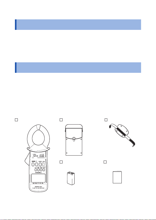
Checking Package Contents
Once you have received the instrument, verify that it has not suffered
any damage during shipment before using it. If you discover any
damage or nd that the instrument does not operate as stipulated in
its specications, please contact your authorized Hioki distributor or
reseller.
Verify that the packaging includes all contents.
3283-20 9399 Carrying Case Hand Strap
6LR61 Alkaline Battery
× 1
Instruction Manual
1
Page 6
Safety Information
Safety Information
The 3283-20 has been designed and tested in accordance with the
IEC 61010 safety standard and shipped in a safe state. However,
failure to adhere to the precautionary information and follow the
instructions provided in this manual may render safety-related
functionality provided by the instrument inoperable.
Before using the instrument, be sure to carefully read the following
safety information.
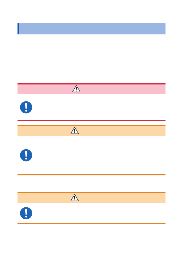
DANGER
Improper use of the instrument may result in bodily
injury or equipment damage. Read this instruction
manual carefully and ensure that you understand its
contents before operating the instrument.
WARNING
Electricity poses a number of hazards, including electric
shock, overheating, fire, and arc discharge (caused
by a short). Individuals using an electrical measuring
instrument for the first time should be supervised
by a technician who has experience in electrical
measurement.
Protective gear
WARNING
To avoid electric shock when measuring live lines,
wear appropriate protective insulation gear and
adhere to applicable laws and regulations.
2
Page 7
Safety Information
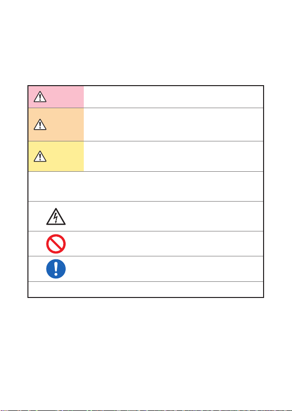
Safety-related notations
This manual classifies safety information on the basis of the
severity of the associated risk and hazard level using the following
categories.
DANGER
Indicates an imminent hazard that could lead to serious
injury or death.
WARNING
CAUTION
IMPORTANT
*
Indicates a hazard that could lead to serious injury or
death.
Indicates a hazard that could lead to minor injury or
that could be expected to result in equipment or other
damage.
Indicates information or content that is especially
important to keep in mind when operating the instrument
or performing maintenance work.
Indicates a high-voltage hazard.
Warns that failure to verify safety or improper use of the
instrument could lead to electric shock, burns, or death.
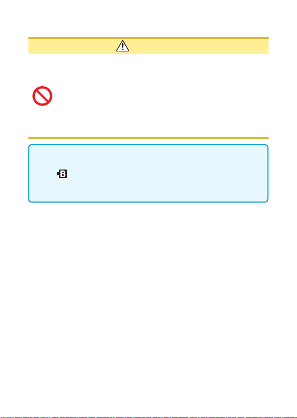
Indicates an action that you must refrain from performing.
Indicates an action that you must perform.
Indicates that there is additional information below.
3
Page 8
Safety Information
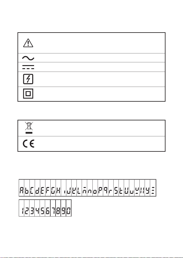
Symbols displayed on the instrument
Indicates the need for caution or a hazard.
When this symbol is displayed on the instrument, refer to the
corresponding section of the instruction manual.
Indicates AC (Alternating Current).
Indicates DC (Direct Current).
Indicates that the instrument may be connected to or
from a live circuit.
Indicates a double/reinforced-insulated device.
Symbols related to standards
Indicates the Waste Electrical and Electronic Equipment
Directive (WEEE Directive) in EU member states.
Indicates that the product conforms to regulations set out by the
EC Directive.
disconnected
Screen display
This instrument uses the following screen displays.
A B C D E F G H I J K L M N O P Q R S T U V W X Y Z
1 2 3 4 5 6 7 8 9 0
4
Page 9
A different display is used in the case below.
Over-range indication (p. 17).
Other notations
Safety Information
HOLD
(
Bold text is used to indicate language used on keys and other
Bold
)
controls.
[ ] Language from the screen is enclosed in brackets ([ ]).
Accuracy
We dene measurement tolerances in terms of rdg. (reading) and
dgt. (digit) values, with the following meanings:
(Reading or displayed value)
The value currently being measured and indicated on the
rdg.
measuring instrument.
(Resolution)
The smallest displayable unit on a digital measuring instrument,
dgt.
i.e., the input value that causes the digital display to show a “1”
as the least-signicant digit.
5
Page 10
Safety Information
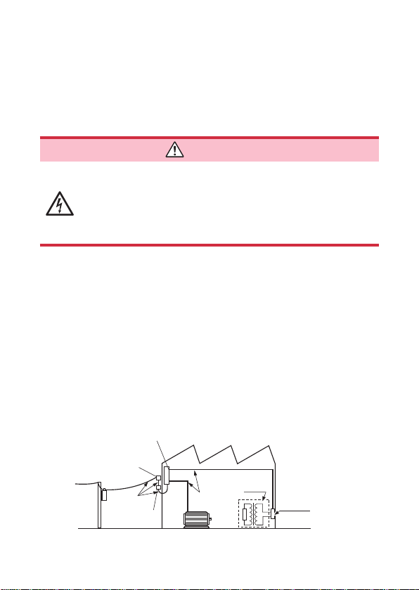
Measurement categories
To ensure safe operation of measurement instruments, IEC 61010
establishes safety standards for various electrical environments,
categorized as CAT II to CAT IV, and called measurement
categories.
DANGER
• Never use a measuring instrument whose measurement
category is lower than the location in which it will be
used. Doing so may result in a serious accident.
• Never use a measuring instrument with no category
labeling in a CAT II to CAT IV measurement category.
Doing so may result in a serious accident.
The 3283-20 conforms to the safety requirements for CAT III (300 V)
measuring instruments.
CATⅡ: When directly measuring the electrical outlet receptacles
of the primary electrical circuits in equipment connected
to an AC electrical outlet by a power cord (portable tools,
household appliances, etc.)
CAT Ⅲ: When measuirng the primary electrical circuits of heavy
eqiupment (fixed installations) connected directly to the
distribution panel, and feeders from the distribution panel
to outlets
CAT Ⅳ: When measuring the circuit from the service drop to the
service entrance, and to the power meter and primary
overcurrent protection device (distributi o n pa n e l )
Distribution panel
Service entrance
Service drop
CAT IV
Power meter
Internal wiring
CAT III
Fixed installation
CAT II
T
Outlet
6
Page 11
Operating Precautions
Operating Precautions
Please read the following precautions to ensure that you can use
the instrument safely and fully utilize its functionality.
Checking the instrument before use
Verify that the instrument operates normally to ensure that no
damage occurred during storage or shipping. If you find any
damage, contact your authorized Hioki distributor or reseller.
Installation
WARNING
Installing the instrument in inappropriate locations may
cause a malfunction of instrument or may give rise to an
accident. Avoid the following locations.
• Exposed to direct sunlight or high temperature
• Exposed to corrosive or combustible gases
• Exposed to a strong electromagnetic eld or
charge
• Near induction heating systems (such as high-frequency
induction heating systems and IH cooking equipment)
• Susceptible to mechanical vibrations
• Exposed to water, oil, chemicals, or solvents
• Exposed to high humidity or condensation
• Exposed to high quantities of dust particles
electrostatic
7
Page 12
Operating Precautions
Handling of the instrument
DANGER
• Do not input a voltage or current in excess of the
ratings indicated on instrument labeling or the
measurement range listed in the specifications.
Doing so may cause damage to, or heating of, the
instrument, leading to bodily injury.
• The maximum measurement current varies with the
frequency, and the current that can be measured
continuously is limited. Operating the instrument at
less than this limitation is referred to as derating.
Do not measure currents in excess of the derating
curve. Doing so may result in instrument damage or
malfunction, re, or burns due to sensor heating.
• To avoid short circuits and potentially life-
threatening hazards, never attach the clamp to a
circuit that operates at more than 300 V AC rms.
• Be sure to connect the instrument to the secondary
side of circuit breakers. In the event of a short, this
side of the circuit breaker will be protected from any
short-circuit current by the breaker. The primary
side of circuit breakers is characterized by high
current capacity, and any short-circuit could result
in damage to the instrument or other equipment.
WARNING
To avoid electric shock, do not approach high-voltage
equipment or wiring when taking measurements
using a transformer's ground wire. If measurement
is difficult because the ground wire is located close
to an exposed high-voltage conductor, reroute the
ground wire before measurement.
8
Page 13
Operating Precautions
CAUTION
• Be careful to avoid dropping the instrument or otherwise
subjecting them to mechanical shock, which could
damage the mating surfaces of the jaw and adversely
affect measurement.
• Do not place foreign objects between the mating faces of
the jaw or insert foreign objects into the gaps of the jaw.
Doing so may worsen the performances of the sensor or
interfere with clamping action.
• It may not be possible to accurately measure electrical circuits
that have a superposed DC component.
• The
indicator lights up when the remaining battery capacity
is low. In this case, the instrument's accuracy is not guaranteed.
Replace the battery immediately.
Precautions when transporting the instrument
When shipping the instrument, handle it with care so as to avoid
damage due to vibration or mechanical shock.
9
Page 14

Operating Precautions
10
Page 15

Overview
1
1.1 Overview and Features
The 3283-20 is designed for wide-range measurement of current
in live circuits, from very small leak currents up to load currents of
200 amperes. The jaws are made of material with high magnetic
permeability to minimize adverse effects from external magnetic
elds and error due to the position of the conductor measured,
thus raising accuracy.
High-sensitivity ranges with 10 mA full scale
Accurate measurement even of minute leak currents (resolution
10 μA).
Extensive measurement range
Five ranges in a 10 mA to 200 A full scale, for measurement over
an extensive range.
Built-in microcomputers give multifunctionality
SLOW, MAX and MIN are just some of the functions offered by
this compact, multifunctional instrument.
Displays true RMS values
Packs true-rms conversion circuits for accurate measurements
unaffected by leak current distortion.
Filter functions
The widespread use of switching power supplies and equipment
incorporating inverter technology can cause high-frequency
11
Page 16

Overview and Features
components to be superimposed on leak current waveforms.
The lter functions allow measurement of two kinds of leak
current: the kind caused by insulation faults and the kind that
contains high-frequency components.
Minimized effects from external magnetic elds and
conductor position
The jaws are made of material with high magnetic
permeability, allowing precise measurement near to
transfo r me r s, e l ec t r i c m oto r s a nd ot h er s o urces of magnet i c
elds. And error due to conductor cable position is extremely
low, so that even if the i ns trument is use d as a r e si du al
current transformer, the residual current characteristics are
low and measu re m ent a c c ur ac y is g o o d.
Low power consumption
Rated power: 100 mVA
Approximately 40 hours of continuous operation on single
layered-type manganese dry cell batter y (6F22)
12
Page 17
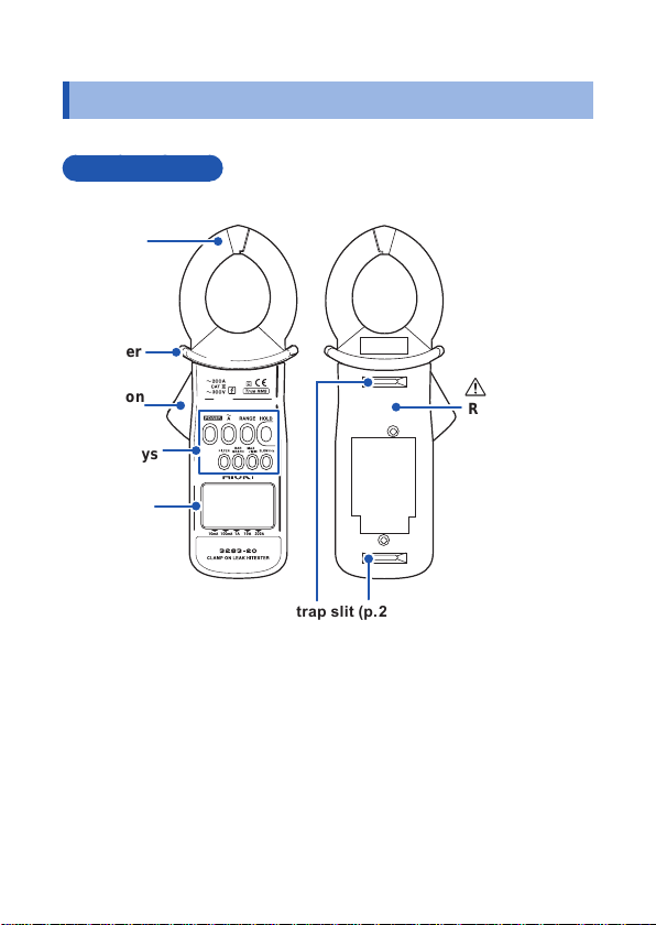
1.2 Parts and Functions
Front and rear
Jaw
Barrier
Parts and Functions
Operation
lever
Control keys
(p. 14)
LCD
display
(p. 15)
Rear cover
(p. 20)
Strap slit (p. 24)
13
Page 18
Parts and Functions
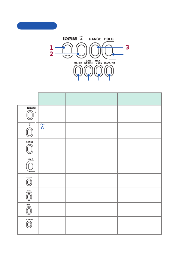
Control keys
1
2
5 6
Key Normally
1
2
3
4
5
6
7
8
POWER key Turns the power on/off –
key
RANGE key Switches the range
HOLD key
FILTER key Turns the lter function
BAR
GRAPH key
MAX/MIN
key
SLOW/Hz
key
Turns the recording
function off (p. 38)
(p. 29)
Turns the data hold
function on/off (p. 36)
on/off (p. 35)
Switches the bar graph
display (p. 32)
Turns the recording
function on (p. 37)
• Setting a sl owe r d is pl ay
update rate (p. 30)
• Freq. measurement (p. 33)
7
8
3
4
Power turned on while
holding key down
–
Disables the buzzer
(p. 42)
Cancels the auto
power-of f (APS)
function (p. 41)
–
–
–
–
14
Page 19
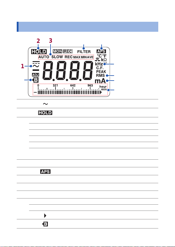
1.3 Liquid Crystal Display
3
2
4
5
Liquid Crystal Display
10
1
1
2
3
4
5
6
7
8
9
10
6
7
8
9
AC measurement (p. 25)
Hold data (p. 36)
AUTO
SLOW Update display approx. 1 time/3 seconds (p. 30)
REC Recording function is on (p. 37)
MAX Maximum value (p. 37)
MIN Minimum value (p. 37)
AVE
FILTER Filter function is enabled (p. 35)
Hz Frequency (p. 33)
RMS Tr ue root- mean- square value (p. 26)
mA Current (A, mA)
hour 1 hour/segment (bar graph)
min 1 minute/segment (bar graph)
Auto ranging is enabled (p. 29)
Average value
(p. 37)
Auto power-off function is enabled (p. 41)
Over-range indication (bar graph)
Batter y depleted (p. 16)
= (maximum value + minimum value)/2
15
Page 20

Liquid Crystal Display
Battery remaining power display
When the power is turned on, all the LCD's segments light up.
Then the model name is displayed, and the bar graph shows the
battery power for 1 second.
Bar graph display with fresh
battery
Power shut-off
16
If the battery
is zero,
the buzzer will sound three
beeps.
When
instrument's accuracy cannot
be assured.
When the battery voltage drops below a
certain level after
will be shut off automatically to protect the
internal memory. [bAtt] and [Lo] will be
displayed to indicate this.
When these are displayed and the power
has been shut off, replace the exhausted
battery with a new one.
remaining power
will light up and
is lighted, the
lights, the power
Page 21

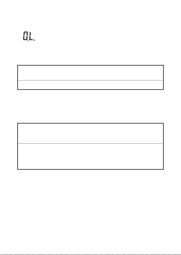
Over-range indication
Liquid Crystal Display
[O.L.] will be displayed if the measured
current or frequency is beyond the
measurement limit.
When this display occurs, select an
appropriate range.
17
Page 22

Liquid Crystal Display
18
Page 23

Pre-measurement Preparation
2
2.1 Flow of Measurement
Before using the instrument, be sure to read
Preparing and connecting-up
Install the battery (p. 20).
Do pre-use checks (p. 23).
(As necessary)
Attach the hand strap (p. 24).
Measuring
Turn the power on.
Clamp the conductor to be measured.
(As necessary)
Select the measurement range (p. 29).
Reduce noise (p. 35).
Ending
Turn the power off.
“Operating Prec autions” (p. 7)
19
Page 24

Installing/Replacing the Battery
2.2 Installing/Replacing the Battery
Before using the instrument for the rst time, install a layered-type
alkaline battery (6LR61) or a layered-type manganese dry cell
battery (6F22). Also, before doing measurement, check that there
is adequate remaining power in the battery. If there is not, replace
the battery.
WARNING
• Battery may explode if mistreated. Do not short
circuit, recharge, disassemble or dispose of in re.
• To avoid electric shock, remove the jaws from the
object to be measured, and remove the rear cover,
before replacing the battery.
• Also, before using the instrument after replacing
the battery, fasten the rear cover with its screws.
• To avoid damage to the instrument or electric
shock accidents, use only the screws that came
with the instrument to fasten the rear cover in
place. If you lose or damage the screws, contact
your authorized Hioki distributor or reseller.
• Handle and dispose of batteries in accordance
with local regulations.
20
Page 25

Installing/Replacing the Battery
CAUTION
Heed the following instructions to avoid battery
performance drop or leakage.
• Pay attention to the polarity markings "+" and "–", so
that you do not insert the battery the wrong way around.
• Do not use a battery beyond its recommended use period.
• Do not leave a depleted battery
• Be sure to replace it with a battery of the specied type.
• Remove the battery and store it if the instrument will
not be in use for a long time.
To avoid damage to the instrument, do not screw the rear
cover screws in too tightly. Torque of about 0.5 N•m is
recommended.
• When appears, the battery is exhausted and accuracy is
not assured. Replace the battery as early as possible.
• Turn the power off before replacing the battery.
• When inst al li ng t he n ew b at t ery, make sure that the ba t te ry
snaps are se c ur el y c o nn ec t ed to i t . If a s na p is l o o se,
adjust it so th at i t is s ec u re ly connect ed. I f t he b attery i sn't
securel y c o nn ec te d, t h e po wer m ay not come on or may
turn of f du r i ng u se.
inside the instrument.
21
Page 26

Installing/Replacing the Battery
Rear
3, 8
4, 7
−
+
5, 6
Prepare the following:
1
• A layered-type alkaline battery
(6LR61) or a layered-type
manganese dry cell battery
(6F22)
• Phillips screwdriver
Turn the instrument's power
2
off.
Loosen the rear cover's two
3
fastening screws, using the
Phillips screwdriver.
Remove the rear cover.
4
Remove the old battery,
5
taking care not to pull on
the battery snap cords.
Firmly install the new
6
battery to the battery
snaps. Be sure to orient the
polarity correctly.
Fasten the rear cover.
7
Screw in the fastening
8
screws to fasten the rear
cover.
22
Page 27

Inspection Prior to Use
2.3 Inspection Prior to Use
Before using the instrument for the rst time, inspect it carefully
to ensure that no damage occurred during shipping. If damage
is evident, or if it fails to operate according to the specications,
contact your dealer or Hioki representative.
Exterior appearance check
Check item Action
• Any breakage or cracks in
the instrument's exterior?
• Any internal circuits
exposed?
Checks when turning on the power
Check item Action
Sufcient bat tery power
remaining?
All LCD segments are
displayed?
Check visually.
If there is any of this damage, the
instrument will not measure correctly. Do
not use the instrument in this condition.
Have it repaired rst.
If the in the left side of the LCD
display lights or if the power is shut off
soon after being turned on, measurement
accuracy cannot be assured and you must
immediately replace the battery with a new
one (p. 20).
Check that all of the LCD's segments light
up (p. 15).
If any of the segments does not light, you
must have the instrument repaired.
23
Page 28

Attaching the Hand Strap
2.4 Attaching the Hand Strap
Strap slits on the back of the instrument can be used for attaching
the included hand strap. Use the hand strap to help prevent
accidental dropping of the instrument.
CAUTION
Attach the strap securely, by inserting it through the
strap slits on the instrument. If the strap is not securely
attached, the instrument may fall and be damaged.
24
Page 29

Performing Measurements
3
3.1 Measuring Leakage Current
DANGER
To prevent electric shock, do not touch any part
beyond the barrier during use (p. 13).
1
Clamp the conductor at the center of the jaw.
2
To measure the ground wire of a circuit, clamp the ground wire only.
(See 1 in the gure)
To measure all the wires of a circuit, clamp them all together in a
bundle. (See 2 in the gure)
Clamp all three of the circuit's
wires in a bundle
Single-phase 3-wire circuit
2
Ig: Leak current
lg
Ground wire
1
2
equipment
Load
25
Page 30

Measuring Leakage Current
3-phase 3-wire circuit
Clamp all three of the circuit's wires in a bundle
2
lg
Load
equipment
1
2
Ground wire
1
Ground wire
• To measure a single-phase 2-wire circuit, clamp both of the
circuit's wires together.
• To measure a 3-phase 3-wire circuit, clamp all 3 of the
circuit's wires bundled together.
• To measure a 3-phase 4-wire circuit, clamp all 4 of the circuit's
wires bundled together. If that is not possible, carry out the
measurement on the equipment's ground wire.
The effective value (RMS) of the leak current
will be shown on the digital display .
26
Page 31

Measuring Leakage Current
• Do not input current that exceeds the current range's
maximum continuous input.
• Measurement may not be accurate in the cases below.
(1) If there is large current (of about 100 A) owing through a
nearby electric line.
(2) If you use the instrument to measure the waveforms on the
secondary side of an inverter, or other special waveforms.
(3) If the jaws are not fully closed.
In cases where the wires are thick, such as with clamping of a
3-phase cable, always make sure that the jaws are fully closed.
When the jaws are not fully closed, error occurs in the measured
values and accuracy cannot be assured.
• Note that a value of several tens of amperes may be displayed
when the jaws are opened or closed or when the current
range is changed, but this is not an error. Simply wait a little
while for the display to return to zero. Or start measurement
before it returns to zero – there will not be any adverse
effects.
• In cold areas, the display may not go to zero when the jaws are
taken off the conductor. This will not affect accuracy, provided that
you are measuring current of or above the 1 mA that is the bottom
limit of the guaranteed accuracy range.
• This instrument is designed for measuring electricity lines
up to CAT III 300 V (voltage to ground). However, in the
exceptional case of a 3-phase 3- or 4-wire line, or similar
line, whose neutral point is grounded ("Y" connection or star
connection), the instrument can be used on lines of up to 500
V line voltage (approx. 289 V voltage to ground) – but only in
such a case.
27
Page 32

Measuring Leakage Current
Locating an insulation failure
For a transformer, rst measure the ground wire to determine
the overall circuit leak current (see 1 in the gure), then use the
variation in the leak current to diagnose the presence or absence
of leakage.
If you diagnose leakage to be present, use bundled measurement
of all the wires to locate it. Start from the power source and work
toward the load.
• Suppose an insulation fault in the wiring has occurred at (1)
in the gure. It will be possible to detect the leak current with
bundled measurement at position 2, but not at 2'.
• Suppose an insulation fault in the load equipment has occurred at
(2) in the gure. It will be possible to detect the leak current with
bundled measurement at position 3, but not at 3'.
• To detect intermittent leak current (occurring only when a certain
piece of equipment is operating), the use of a memory recorder
will be helpful.
Single-phase
3-wire circuit
2
2'
3 3'
Ground wire
28
1
lg
(1)
Load
equipment
Load
equipment
(2)
Page 33

Measuring Leakage Current
Selecting the measurement range
You can set auto or manual ranging.
• Auto ranging The optimal range for the measured values
is set automatically.
• Manual ranging Setting is xed to a particular range.
With the frequency display, only auto ranging is available.
Auto ranging
Measurement will begin with auto ranging
when the power is turned on.
[AUTO] lights up (initial setting)
Manual ranging
10 mA ([AUTO] goes out)
100 mA
1 A
Bars will appear above the
currently selected range.
The gure above shows the
100 mA range selected.
10 A
200 A
Auto ranging ([AUTO] lights up)
29
Page 34

Measuring Leakage Current
Setting a slower display update rate (SLOW)
If the displayed current value uctuates rapidly and is hard to read, you
can set a slower update rate (approx. 1 time/3 seconds) by pressing the
SLOW/Hz key, to make the value easier to read.
[SLOW]
[Hz]
[RMS]
• Setting [Hz] or [RMS] will return the display to the normal update
rate.
• With the frequency display, the update rate cannot be changed.
Setting a faster display update rate (FAST)
A faster rate of approximately 4 times per second can be set for
the display update. This is useful for example to measure load
currents with intense uctuations and in similar applications.
FAST
NORMAL
(Split-second display each
time key is pressed)
Press twice in
succession
If you switch to [SLOW] display while the instrument is in the fast
mode, the display update rate will be the same as [NORMAL]
(approx. 2 times/second).
30
Page 35

Measuring Leakage Current
Measuring an intensely uctuating load current
First set the FAST display update rate and set the appropriate
range using the RANGE key. Then do the measurement.
FAST
NORMAL
1
Press twice in
succession
(Split-second display each
time key is pressed)
2
Set to a xed current range.
• If you don't know the magnitude of the current to be
measured, select the 200 A range.
• Using the recording function to retain the maximum value will
make it easier to take readings (p. 37).
31
Page 36

Measuring Leakage Current
Obtaining bar graph displays (BAR GRAPH)
You can have the current range displayed as a bar graph.
The bar graph will show the rms value of the measured current.
The bar graph display update rate will be FAST (approx. 4
times/second).
Current range display
The flas hing s egm ent in t he bar g rap h indi cat es th e full - sc ale
position.
Bar-graph display
32
Page 37

Measuring Leakage Current
Displaying the frequency (Hz)
When [SLOW] is displayed:
[SLOW]
[Hz]
[RMS]
The frequency of the current being measured
will be displayed.
If there is no input, or input is lower than 30 Hz,
"----" will be displayed.
• Enable the lter function when conducting measurement in
the cases below (p. 35).
(1) If meaningless data is displayed due to noise.
(2)
If you use the instrument to measure the waveforms on the
secondary side of an inverter, or other special waveforms.
• The instrument may not be able to perform measurement in
the cases below.
(1)
If the input current is 1/10 or less of the current range (fullsc ale).
(2)
If you measure high frequencies with the lter function
enabled.
• The frequency range is set automatically. If you press the
RANGE key, only the current range will be changed.
33
Page 38

Measuring Leakage Current
Measuring load current
To measure load current, clamp just one wire of the conductor.
The measurement will not be possible if you clamp both wires of a
single-phase cable or all 3 wires of a 3-phase cable.
OK
• The instrument may not be able to measure certain special
waveforms, for example on the secondary side of an inverter.
• Depending on the magnitude and frequency of the input
current, resonance may cause the jaws to emit noises, but
this will not affect the measurement.
• If you don't know the magnitude of input current, disable the
lter function and begin measurement with auto ranging or
with the 200 A range set.
NO
NO
34
Page 39

Reduci ng Noise ( Filter Func tion – FILTER)
20
1 10 100 1000 10000 100000
3.2 Reducing Noise
(Filter Function – FILTER)
The widespread use of switching power supplies and equipment
incorporating inverter technology can cause high-frequency
components to be superimposed on leak current waveforms. Use the
lter function to eliminate unwanted high-frequency components.
FILTER OFF FILTER ON
The frequency bandwidth with the lter function enabled is limited to
approximately 180 Hz (-3 dB), comparable to the frequency bandwidth
for an ordinary leakage breaker. It is recommended that the lter
function be used when analyzing leakage breaker operation.
10
FILTER: OFF
0
-10
-20
Amplitude [dB, 0 dB = 1 V ]
-30
Frequency bandwidths (with 10 mA current range used)
FILTER: ON
Frequency [Hz]
35
Page 40

Hold Dat a (Data H old Funct ion – HOL D)
3.3 Hold Data (Data Hold Function –
HOLD)
Use this to freeze the displayed data (put it on hold) for easy
reading.
OFF ON
36
Page 41

Check ing Max imum, Min imum and Average Values (Recor ding Funct ion – REC)
Checking Maximum, Minimum and
3.4
Average Values
Use the recording function to display the maximum/minimum measurement
value, the average of the maximum and minimum, or the instantaneous value .
(Recording Function – REC)
1
Select the current range.
2
The maximum, minimum, average or
instantaneous value for the period
from when the MAX/MIN key was last
pressed up to the present moment will
be displayed. The other data will be
retained in the internal memory. ([REC]
will ash)
[MAX], [MIN] and [AVE] displays Measurement value displayed
[MAX] Maximum value
[MIN] Minimum value
[AVE]
None Instantaneous value
Average value = (maximum value +
minimum value)/2
Press the MAX/MIN key
while current is being
measured
.
• Pressing the MAX/MIN key during auto ranging ([AUTO])
xes the range at the current setting.
• When you use the recording function, auto power-off will be
turned off automatically.
37
Page 42

Check ing Max imum, Min imum and Average Values (Recor ding Funct ion – REC)
3
Halt the recording
function.
(
4
lights, [REC] lights up)
Maximum value [MAX]
Minimum value [MIN]
Average va lue [AVE]
Instantaneous value
5
Turn the recording
function back on.
(
Turning the recording function off
The maximum, minimum or average value
will be cleared. ([REC] will go out)
goes out, [REC] a sh es)
38
Page 43

Check ing Max imum, Min imum and Average Values (Recor ding Funct ion – REC)
• The elapsed time count will stops for as long as lights
steady.
• Momentary power loss and power surges cannot be detected in
this mode.
• The maximum, minimum or average value will be cleared when
the power is turned off.
• The duration that the recording function can be used for depends
on the remaining battery capacity. Use a new lay ered-type alkaline
battery (6LR61) when using it for a long duration.
• The lowest frequency that can be displayed is 30.0 Hz.
• If you clamp the conductor after enabling the recording function,
there will be no input and so the minimum value will be zero. To
prevent this, clamp the conductor before pressing the MAX/MIN
key to enable the recording function.
• If you take the jaws off the conductor with the recording
function still enabled, the input will stop and so the minimum
value will be zero. To prevent this, press the HOLD key to halt
the recording function before taking the jaws off the object.
Bar graph displays (BAR GRAPH)
You can switch the bar graph between different displays.
RMS value display
(instantaneous value)
Elapsed time (hou rs) [hour]
Elapsed time (minut es) [min]
Current range display
When you set one of the elapsed time displays, a segment in the
bar graph will ash to indicate the time that has elapsed since the
MAX/MIN key was last pressed.
39
Page 44

Check ing Max imum, Min imum and Average Values (Recor ding Funct ion – REC)
When [min] is displayed at the right end of the bar graph:
1 segment in the bar graph represents 1 minute. The segment
for the currently elapsing minute ashes, and when the minute
has elapsed, that segment stops ashing and lights steady. The
segments do this one after the other, starting from the left end of
the graph and going rightward. When all the bar graph's segments
are lighted steady, 30 minutes have elapsed. From then on, the
segments will once more ash one by one from left to right, to
indicate the elapsing minute, but this time the ashing segment will
go out with each minute that elapses.
When the segments to the left of the ashing segment
are lighted steady:
The number of steady-lighted segments
represents the elapsed time in minutes
(0 to 29).
The example shows the display for
elapsed time = 20 minutes.
When the segments to the right of the ashing segment
are lighted steady:
The number of segments that have
gone out represents the elapsed
time (+ 30) in minutes (30 to 59).
The example shows the display for
elapsed time = 50 minutes.
When [hour] is displayed at the right end of the bar graph:
1 segment in the bar graph represents
1 hour. Up to 59 hours of elapsed time
can be displayed.
The example shows the display for
elapsed time = 1 hour 40 minutes
.
40
Page 45

Limiti ng Batte ry's Po wer Cons umption (Auto power-off f unctio n – APS)
Limiting Battery's Power Consumption
3.5
(Auto power-off function
Use this to limit the battery's power consumption. It turns the power
off automatically if the instrument is not operated for 10 minutes.
The APS function is congured at the factory to enabled (this is the
initial setting). ( lights up)
When APS is enabled, on the LCD display will ash, and a
beep will sound to warn you that the instrument will automatically
turn off in 30 seconds. To continue using the instrument, press any
key other than the POWER key. But note that even so, the power
will be shut of f automatically after another 10 minutes if you leave
the instrument unoperated for that period once more.
• When operating the instrument continuously for a long
duration, disable the auto power-off function in advance.
• Using the recording function disables the APS function.
Disabling the auto power-off function
If the power is on, turn it off.
– APS)
+
When you power up again, the buzzer will beep
twice and the APS function will be disabled.
( goes out)
Auto power-off will be disabled up until the power is turned off.
Be aware of this if the battery is low.
Press these
simultaneously
41
Page 46

Disabling the Buzzer
3.6
Disabling the Buzzer
The buzzer is congured at the factory to enabled (this is the initial
setting). To change this setting, rst turn the power off.
+
When you power up again, the buzzer will beep twice. Then it will be
disabled.
The buzzer will be disabled up until the power is turned off.
Press these simultaneously
42
Page 47

Specications
4
• rdg. (Reading or displayed value)
The value currently being measured and indicated on the measuring
instrument.
• dgt. (Resolution)
The smallest displayable unit on a digital measuring instrument, i.e.,
the input value that causes the digital display to show a “1” as the least-
signicant digit.
4.1 Measurement Specications
Conditions of
guaranteed
accuracy
Diameter of
measurable
conductors
Guaranteed accuracy period:
Guaranteed accuracy period
from adjustment made by
Hioki:
Number of jaw openingclosings:
Temperature and humidity for
guaranteed accuracy:
Battery low indicator
φ40 mm max.
must not be on.
1 year
1 year
Up to 10,000
23°C±5°C (73°F±9°F),
80% RH or less
43
Page 48

Measurement Specications
AC current: A rms (display of true rms)
Range
(accuracy range)
10.00 mA
(1.00 mA to 10.00 mA)
100.0 mA
(10.0 mA to 100.0 mA)
1.000 A
(0.100 A to 1.000 A)
10.00 A
(1.00 A to 10.00 A)
200.0 A
(10.0 A to 200.0 A)
Effect of
conductor position
Effects of ex ternal
magnetic elds
Maximum rated
voltage to ear th
Resolution Accuracy
0.01 mA
0.1 mA
0.001 A
0.01 A
0.1 A
Within ±0.1% rdg. (with any position relative to the
center of the jaw and current under 100 A)
Within ±0.5% rdg. (with current 100 A or higher)
Equivalent of 5 mA, max. 7.5 mA, with external
magnetic eld of 40 0 A/m AC
300 V AC (Measurement Category III)
Anticipated transient overvoltage: 4000 V
FILTER OFF:
45 Hz to 66 Hz:
±1.0% rdg. ±5 dgt.
40 Hz to 45 Hz,
66 Hz to 2 kHz:
±2.0% rdg. ±5 dgt.
FILTER ON:
50 Hz to 60 Hz:
±1.5% rdg. ±5 dgt.
FILTER OFF:
45 Hz to 66 Hz:
±1.5% rdg. ±5 dgt.
40 Hz to 45 Hz,
66 Hz to 2 kHz:
±2.0% rdg. ±5 dgt.
FILTER ON:
50 Hz to 60 Hz:
±2.0% rdg. ±5 dgt.
Maximum
allowable
current
20 A
AC rms,
continuous
(p. 47)
200 A
AC rms,
continuous
(p. 47)
44
Page 49

General Specications
Frequency Hz
Range (accuracy range) Resolution Accuracy
100.0 Hz (30.0 Hz to 99.9 Hz) 0.1 Hz ±0.3% rdg. ±1 dgt.
1000 Hz (95 Hz to 1000 Hz) 1 Hz ±1.0% rdg. ±1 dgt.
The frequency range is set automatically. If you press the RANGE
key in the frequency display mode, only the current range will be
changed.
4.2 General Specications
Auxiliary functions
Recording Maximum ([MAX]), minimum ([MIN]), and
Data hold Puts display on hold
Auto power-off Sounds intermittent beep alert and shuts off
Battery low voltage
power-off
Beep tone ON/OFF
LCD display
Digital indication 2000 counts, displaying values less than or
Bar-graph indication 35 segments
Over-range indication [O.L.] display (using 7 segments); bar-graph
average ([AVE]) value displayable for AC
current and frequency measurement
power automatically approximately 10 minutes
after last key operation (Shut-off can be
delayed or canceled)
When the battery voltage falls below a certain level,
this shuts the power off to prevent malfunctions
equal to 5 counts with a zero
Range display or rms display can be selected
display
45
Page 50

General Specications
Battery low warning
Battery low power- off [bAtt] → [Lo]
Data holding indication
Auto power- off indication
(This indicator lights to indicate the battery
is low. When this is lighted, accuracy is not
guaranteed.)
is displayed (using 7 segments),
then power is shut off
Other functions
Filter functions ON: 180 Hz ±30 Hz (-3 dB) / OFF
Display update rate • Digital indication
Display response time With AC current and frequency: 2.2 seconds
Ranging • For AC current: auto ranging or manual
Circuit dynamic
characteristic
(crest factor)
Dielectric withstand
voltage
Insulation resistance Between jaws and circuitry: 630 k
Operating environment Indoors, Pollution Degree 2, altitude up to
NORMAL 500 ms ±25 ms
(approx. 2 times/second)
SLOW 3 s ± 0.15 s
(approx. 1 time/3 seconds)
FAST 250 ms ±12.5 ms
(approx. 4 times/second)
• Bar-graph indication
250 ms ±12.5 ms (approx. 4 times/second)
or less
(xed) ranging can be selected
• Frequency:
Auto ranging
2.5 max. (max. 1.5 with 200 A range)
Between jaws and hand-held portion:
4.29 kV AC/minute
Ω
or higher
2000 m (6562 ft.)
46
Page 51

General Specications
10 100 1000 10000 100000
Standards Safety: EN61010
EMC: EN61326
Dust-proof, water-proof IP40 (EN60529)
Operating temperature
and humidity
Temperature
characteristics
0°C to 40°C (32°F to 104°F), 80% RH or less
(non-condensing)
In 0°C to 40°C (32°F to 104°F) range: 0.05 ×
accuracy specications/°C
Storage temperature -10°C to 50°C (14°F to 122°F) (non-
condensing)
Power supply Layered-type alkaline battery (6LR61) × 1, or
layered-type manganese dry cell battery
(6F22) × 1
Rated supply voltage: 9 V
Maximum rated power 100 mVA
Continuous operating
time
Approx. 40 hours (when unloaded and using a
layered-type manganese battery (6F22))
Dimensions Approx. 62 mm (2.44″) W × 225 mm (8.86″) H
× 39 mm (1.54″) D
Mass Approx. 400 g (14.1 oz.) (excluding battery)
Produc t warranty period 1 year
Accessories See “Checking Package Contents” (p. 1).
Frequency-dependent derating characteristics
250
200
150
100
Current [A rms]
50
0
Frequency [Hz]
47
Page 52

General Specications
48
Page 53

Maintenance and Servicing
5
WARNING
Touching any of the high-voltage points inside the
instrument is very dangerous.
Customers are not allowed to modify, disassemble,
or repair the instrument. Doing so may cause re,
electric shock, or injury.
5.1 Repair, Inspection and Cleaning
Calibration of the instrument
How often you should calibrate the instrument will depend on the
usage conditions and the environment. Determine a calibration
interval that is suited to your usage conditions and environment,
and request to have calibration done by Hioki.
49
Page 54

Repair, Inspection and Cleaning
Cleaning
CAUTION
If foreign matter gets jammed in the jaw tips, do not
attempt to remove it by forcibly opening/closing the
jaws. Remove it gently with a soft brush or similar.
Foreign matter must be removed, or measurement will
not be accurate. It will also not be accurate if the jaws
are deformed, by foreign matter or other cause. If the
jaws become deformed, contact your authorized Hioki
distributor or reseller.
• To clean the instrument, wipe it gently with a soft cloth
moistened with water or neutral detergent.
• Clean the display area by wiping it gently with a soft dry cloth.
IMPORTANT
Never use solvents containing benzene, alcohol, acetone, ether,
ketone, thinner, gasoline, or similar to clean the instrument. Deformation
or discoloration may result.
Disposal of the instrument
Dispose of the instrument in accordance with local regulations.
50
Page 55

Troubleshooting
5.2 Troubleshooting
If a problem occurs with the instrument, rst carry out the checks
in "Troubleshooting checklist" below. If the problem persists,
contact your authorized Hioki distributor or reseller.
Troubleshooting checklist
Problem Cause Solution
Power will not turn on
Power shuts off
during operation
lights up
lights, followed
by immediate power
shutdown
Power turns off
immediately after it
is turned on
The battery may be low
or depleted.
The battery snap
terminals may be
stretched causing contact
failure.
With the auto poweroff function enabled,
the power is shut off
automatically if the
instrument is not opera ted
for 10 minutes.
The battery may be low
or depleted.
Replace it with a new
batter y (p. 20)
Remove the battery, then
use radio pliers or similar
to readjust the battery
snap terminals.
Check the settings
for the APS function
(p. 41).
Replace it with a new
batter y (p. 20).
Range cannot be
changed
Recording function
([MAX]/[MIN]/[AVE]
display) is operating
– this renders range
change impossible.
Press the
turn off the recording
function. Then change
the range (p. 38).
key to
51
Page 56

Error Displays
Problem Cause Solution
Any of [E.001] to
[E.004] is displayed
The jaws generate
a sound during
measurement
Internal memory may
be damaged.
When large current or
high-frequency current
is measured, resonance
may occur, generating
a sound.
5.3 Error Displays
Have the instrument
repaired (p. 52)
The loudness will depend
on the individual case,
but the sounds will not
affect the measurement.
Error
display
[E. 001]
[E. 002]
[E. 003]
[E. 004]
Checksum error in single-chip
microcomputer's internal ROM.
R/W error in single-chip
microcomputer's internal RAM.
EEPROM checksum error.
Denition Solution
If any of these errors
is displayed in the LCD
display area, repair
is required. Contact
your authorized Hioki
distributor or reseller for
repair.
5.4 Message Displays
Display Denition See page
Battery depleted.
Replace it with a new battery.
52
p.20
Page 57

Message Displays
Display Denition See page
There is abnormality in the internal ROM
or EEPROM data. Have the instrument
repaired.
This is displayed if the measured current
or frequency is beyond the measurement
limit. Select an appropriate range.
When frequency display is set, this
message indicates that there is no input or
that the frequency is under 30 Hz.
p.52
–
p.33
53
Page 58

Error Displays
54
Page 59

13-09
Page 60

Page 61

Page 62

 Loading...