

Page 1

3283
CLAMP ON
LEAK HiTESTER
INSTRUCTION MANUAL
Page 2

Page 3
i
Contents
Introduction 1
Inspection
1
Safety Notes
2
Notes on Use
5
Chapter Summary
11
Chapter 1 Product Outline
13
1.1 Product Outline
13
1.2 Features
13
1.3 Parts and Functions
16
Chapter 2 Measurement Procedure
19
2.1 Preparations
19
2.2 Leak Current Measurement
A
20
2.3 Filter Function FILTER
27
2.4 Data Hold Function
HOLD
28
2.5 Recording Function REC
28
2.6 Auto Power-Off Function
APS
33
2.7 Battery Low Warning
33
2.8 Beep Tone
33
2.9 Fast Mode
34
2.10 Output Function OUTPUT
35
Chapter 3 Battery Replacement
39
Chapter 4 Attaching the Hand Strap
41
Chapter 5 Specifications
43
5.1 Measurement Specifications
43
5.1.1 AC current Arms(true rms indication)
44
5.1.2 Frequency Hz
45
5.2 General Specifications
46
Chapter 6 Troubleshooting
51
Chapter 7 Service
55
Page 4

ii
Page 5

1
__________________________________________________
_____________________________________________
Introduction
Inspection
Thank you for purchasing the HIOKI "3283
CLAMP ON LEAK HiTESTER." To obtain
maximum performance from the product,
please read this manual first, and keep it
handy for future reference.
We have tried to bring this manual as close
to perfection as we could achieve. If
perchance you find any unclear portions,
mistakes, omissions, or the like, we would be
most obliged if you could please notify us of
them via any HIOKI agent, or directly.
When you receive the product, inspect it
carefully to ensure that no damage occurred
during shipping. In particular, check the
accessories, panel switches, keys, and
terminals. If damage is evident, or if it fails to
operate according to the specifications, contact
your dealer or HIOKI representative.
Accessories
9399 Carrying Case 1
Hand Strap 1
Battery: 6F22(006P) 1
Instruction manual 1
Options
9094 OUTPUT CORD
9445-02 AC ADAPTER
(SA10-0910N, SINO-AMERICAN)
9445-03 AC ADAPTER (EU)
(SA10-0910G, SINO-AMERICAN)
Page 6

2
__________________________________________________
_____________________________________________
DANGER
This product is designed to conform to IEC
61010 Safety Standards, and has been
thoroughly tested for safety prior to shipment.
However, mishandling during use could result
in injury or death, as well as damage to the
product. Be certain that you understand the
instructions and precautions in the manual
before use. We disclaim any responsibility for
accidents or injuries not resulting directly from
product defects.
Safety Notes
This manual contains information and warnings
essential for safe operation of the product and
for maintaining it in safe operating condition.
Before using the product, be sure to carefully
read the following safety notes.
Page 7
3
__________________________________________________
_____________________________________________
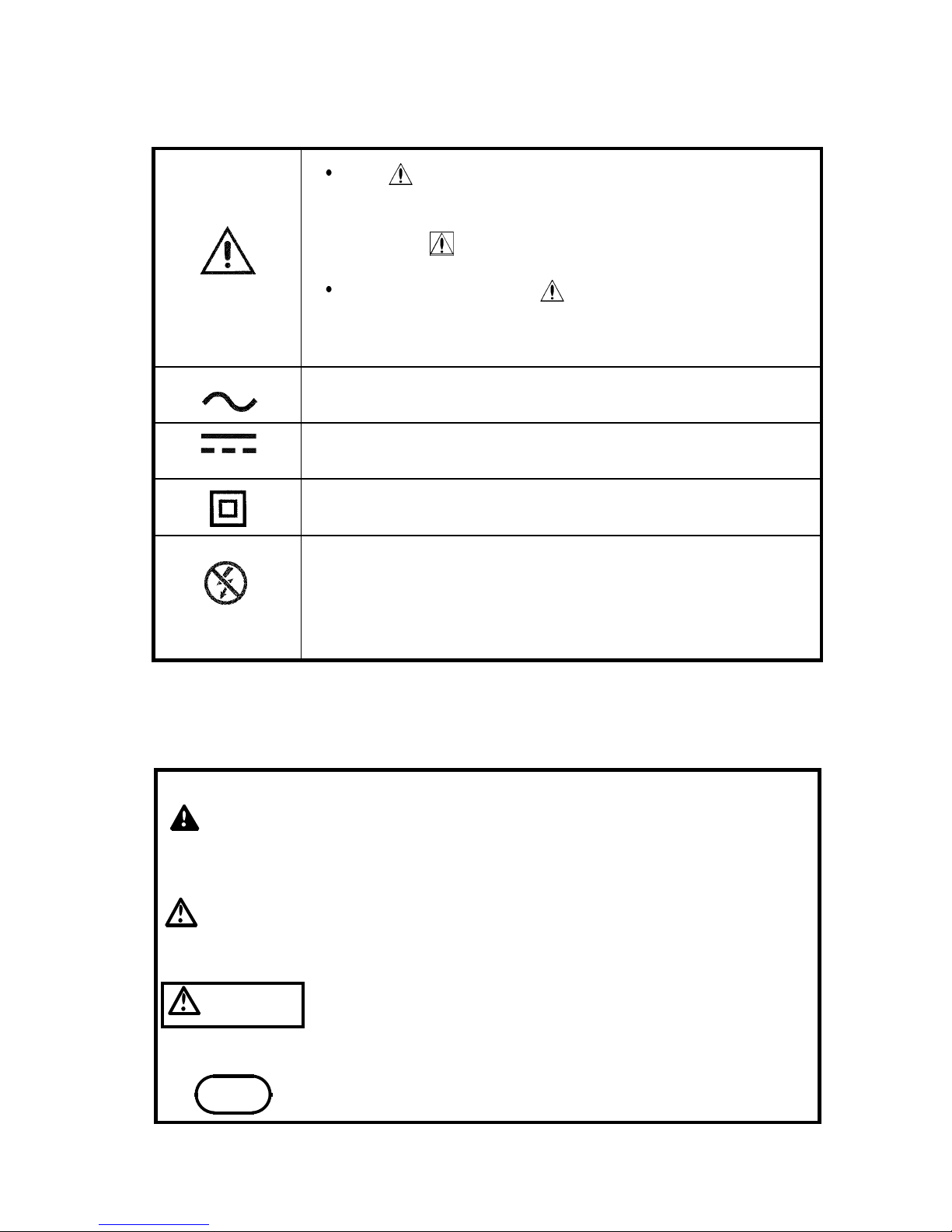
The symbol printed on the product
indicates that the user should refer to a
corresponding topic in the manual (marked
with the symbol) before using the
relevant function.
In the manual, the symbol indicates
particularly important information that the
user should read before using the product.
Indicates AC (Alternating Current).
Indicates DC (Direct Current).
Indicates a double-insulated device.
Wear appropriate protective insulation
(insulating rubber gloves and boots, helmet
and etc.) when connecting and disconnecting
from live electric circuits.
DANGER
Indicates that incorrect operation presents an
extreme hazard that could result in serious
injury or death to the user.
WARNING
Indicates that incorrect operation presents a
significant hazard that could result in serious
injury or death to the user.
CAUTION
Indicates that incorrect operation presents a
possibility of injury to the user or damage to
the product.
NOTE
Advisory items related to performance or
correct operation of the product.
Safety symbols
The following symbols in this manual indicate
the relative importance of cautions and
warnings.
Page 8

4
__________________________________________________
_____________________________________________
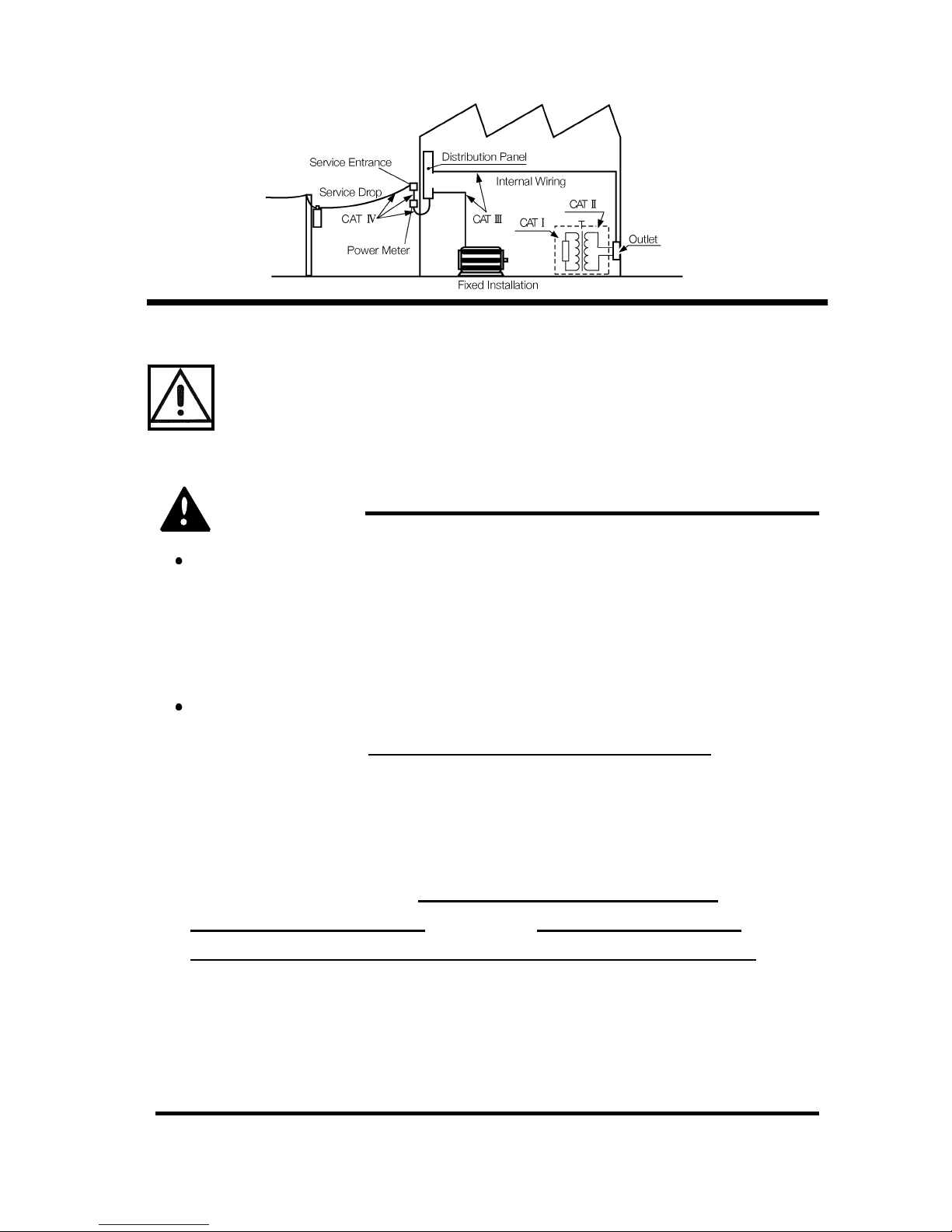
CAT I Secondary electrical circuits connected to an AC
electrical outlet through a transformer or similar
device.
CAT II Primary electrical circuits in equipment connected to
an AC electrical outlet by a power cord (portable tools,
household appliances, etc.)
CAT III Primary electrical circuits of heavy equipment (fixed
installations) connected directly to the distribution
panel, and feeders from the distribution panel to
outlets.
CAT IV The circuit from the service drop to the service
entrance, and to the power meter and primary
overcurrent protection device (distribution panel).
Measurement categories
(Overvoltage categories)
This product complies with CAT III safety
requirements.
To ensure safe operation of measurement
product, IEC 61010 establishes safety
standards for various electrical environments,
categorized as CAT I to CAT IV, and called
measurement categories. These are defined as
follows.
Higher-numbered categories correspond to
electrical environments with greater momentary
energy. So a measurement device designed for
CAT III environments can endure greater
momentary energy than a device designed for
CAT II.
Using a measurement product in an
environment designated with a higher-numbered
category than that for which the product is rated
could result in a severe accident, and must be
carefully avoided.
Never use a CAT I measuring product in CAT
II, III, or IV environments.
The measurement categories comply with the
Overvoltage Categories of the IEC60664
Standards.
Page 9
5
__________________________________________________
_____________________________________________
DANGER
Before using the product the first time, verify
that it operates normally to ensure that the no
damage occurred during storage or shipping. If
you find any damage, contact your dealer or
Hioki representative.
When conductors being measured carry in
excess of the safe voltage level (SELV-E)
and
not more than 300 V, to prevent short circuits
and electric shock while the clamp sensor jaw
is open, make sure that conductors to be
measured are insulated with material
conforming to (1) Overvoltage Category
Ⅲ
,(2)
Pollution Degree 2
, and (3) Basic Insulation
Requirements for Working Voltages of 300 V.
Refer to the following standards regarding the
meanings of underlined terms.
IEC61010-1
IEC61010-2-031
IEC61010-2-032
Notes on Use
Follow these precautions to ensure safe
operation and to obtain the full benefits of the
various functions.
Page 10

6
__________________________________________________
_____________________________________________
DANGER
Do not use clamp testers on bare conductors.
When the clamp sensor jaw is open, there is a
risk of short-circuits and accidents that could
result in injury or death.
Use clamp testers only on power lines up to AC
300 V rms, to avoid short-circuits and accidents
that could result in injury or death.
This product should only be connected to the
secondary side of a breaker, so the breaker can
prevent an accident if a short circuit occurs.
Connections should never be made to the
primary side of a breaker, because unrestricted
current flow could cause a serious accident if a
short circuit occurs.
Use only the specified Model 9445-02 (SA100910N, SINO-AMERICAN) or 9445-03 (for EU)
(SA10-0910G, SINO-AMERICAN). AC adapter
input voltage range is 100 to 240 V AC (with
10% stability) at 50/60 Hz. To avoid electrical
hazards and damage to the product, do not
apply voltage outside of this range.
Page 11

7
__________________________________________________
_____________________________________________
WARNING
To avoid electric shock, do not allow the
product to get wet, and do not use it when your
hands are wet.
To avoid electric shock when measuring live
lines, wear appropriate protective gear, such as
insulated rubber gloves, boots and a safety
helmet.
To avoid electric shock when measuring the
ground conductor on a transformer Class 2
connection site, be careful not to approach high
voltage devices or conductors. Also, if close to
high voltage charging devices or if
measurement is otherwise difficult, first change
the route of the grounding wire.
To avoid electric shock when replacing the
batteries, first disconnect the clamp portion
from the object to be measured. Also, before
using the product after replacing the batteries,
replace the cover and screw.
When replacing the batteries, be sure to insert
them with the correct polarity. Otherwise, poor
performance or damage from battery leakage
could result.
To avoid the possibility of explosion, do not
short circuit, disassemble or incinerate
batteries.
Handle and dispose of batteries in accordance
with local regulations.
Page 12
8
__________________________________________________
_____________________________________________
CAUTION
This is a precision instrument: do not clamp any
foreign objects in the end of the clamp sensor, or
insert anything in the clamp sensor gap.
To avoid damage to the product, protect it from
vibration or shock during transport and handling,
and be especially careful to avoid dropping. Do not
exert excessive pressure on the clamp sensor or
attempt to wedge the sensor into a tight spot for
measurement.
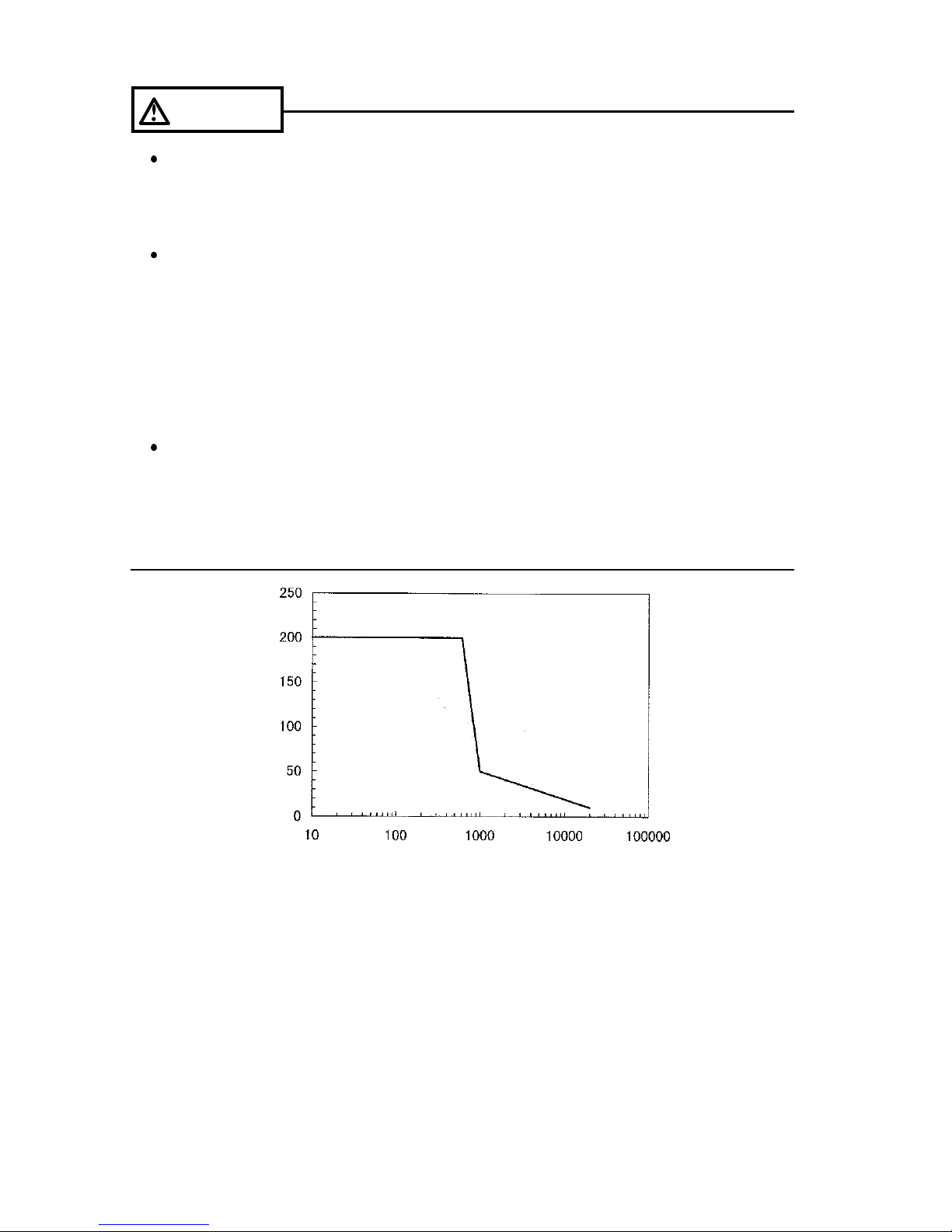
To avoid damage to the product, do not exceed the
maximum input current rating, which depends on
the frequency of the current being measured (see
following Figure).
Frequency [Hz]
Fre
q
uency-dependent deletion characteristics
C
u
r
r
e
n
t
[
A
]
Page 13

9
__________________________________________________
_____________________________________________
CAUTION
Do not use the unit if the battery is exhausted
(when the mark lights in the display area). Be
sure to replace the exhausted battery with a new
one.
When replacing the battery, make sure that the
metal battery snap fitting is firmly connected. If the
metal fitting is loose, adjust it and recheck the
connection. If it isn't connected securely, the power
may not be turned on, and a power may be turned
off during the use.
Adjustments and repairs should be made only by
technically qualified personnel.
For the inside memory protection, make sure the
power is turned off before connecting or
disconnecting the AC adapter.
This product is designed for indoor use, and
operates reliably from 0 to 40 .
Do not store or use the product where it could be
exposed to direct sunlight, high temperature or
humidity, or condensation. Under such conditions,
the product may be damaged and insulation may
deteriorate so that it no longer meets specifications.
Page 14

10
__________________________________________________
_____________________________________________
NOTE
For circuits which carry several superimposed
currents, correct measurements may not be
obtained.
Accurate measurement may be impossible in
the presence of strong magnetic fields, such
as near transformers and high-current
conductors, or in the presence of strong
electromagnetic fields such as near radio
transmitters.
Page 15

11
__________________________________________________
_____________________________________________
Chapter Summary
This manual consists of the following chapters.
"Introduction", "Safety Notes", "Notes on Use"
describe precautions on use, overview, and
features of this unit.
Be sure to read them all. Next, check Chapter
1 to 3 and the unit to confirm your
understanding of the function.
Chapter 1 Product Outline
Explains the parts and functions of the unit.
Chapter 2 Measurement Procedure
Explains how to use the 3283 for measurement.
Chapter 3 Battery Replacement
Explains how to replace the battery used to
power the 3283.
Chapter 4 Attaching the Hand Strap
Explains how to attach the hand strap, for easy
handling of the unit in the field.
Chapter 5 Specifications
Lists the specifications of the 3283 CLAMP ON
LEAK HiTESTER.
Chapter 6 Troubleshooting
Describes points to check before requesting
service.
Chapter 7 Service
Explains how to get the unit serviced.
Page 16

12
__________________________________________________
_____________________________________________
Page 17

13
__________________________________________________
Chapter 1 Product Outline
_____________________________________________
Chapter 1
Product Outline
1.1 Product Outline
1.2 Features
The 3283 CLAMP ON LEAK HiTESTER is
designed for wide-range measurement on live
circuits, from very small leak currents up to load
currents of 200 amperes. The clamp part is
made of material with high magnetic
permeability, to minimize adverse effects
caused by external magnetic fields, and to
reduce tolerances due to the position of the
measured conductor.
High-sensitivity range with 10 mA full-scale point
Allows accurate measurement even of minute
leak currents (resolution 10μA).
Wide measurement range
Five range settings from 10 mA to 200 A make
the 3283 suitable for many applications.
Microprocessor-controlled functions
In spite of the compact dimensions of the unit,
versatile functions such as SLOW and MAX/MIN
are made possible by the built-in
microprocessor.
Page 18

14
__________________________________________________
Chapter 1 Product Outline
_____________________________________________
True rms indication
The true rms conversion circuit delivers accurate
results not affected by leak current distortion.
Filtering
The widespread use of switching power supplies
and equipment incorporating inverter technology
frequently causes harmonics to be
superimposed in the leak current waveform. The
filter in the 3283 allows two kinds of
measurement, for leak current caused by
insulation faults and for leak currents including
harmonics.
Output jack
The output jack allows easy connection to a
level recorder or other equipment (level
recorder output: DC, waveform output: AC).
Unaffected by external magnetic fields and
conductor position
The clamp sensor and magnetic shield are
made of material with high magnetic
permeability, allowing precise measurement also
in the vicinity of transformers, electric motors
and other sources of magnetic fields. Since the
influence of the conductor position on the
measurement result is negligible, residual
current characteristics are not a problem even
when using the unit as a zero-phase
transformer.
Low power consumption
Power consumption is less than 100 mV A,
allowing the unit to operate continuously for up
to 40 hours on a single 6F22 (006P) battery.
Page 19

15
__________________________________________________
Chapter 1 Product Outline
_____________________________________________
Dual power supply design
The unit can be powered using the optional
9445-02 AC adapter (SA10-0910N, SINOAMERICAN), 9445-03 AC adapter (for EU)
(SA10-0910G, SINO-AMERICAN), or from a
battery.
Page 20
16
__________________________________________________
Chapter 1 Product Outline
_____________________________________________
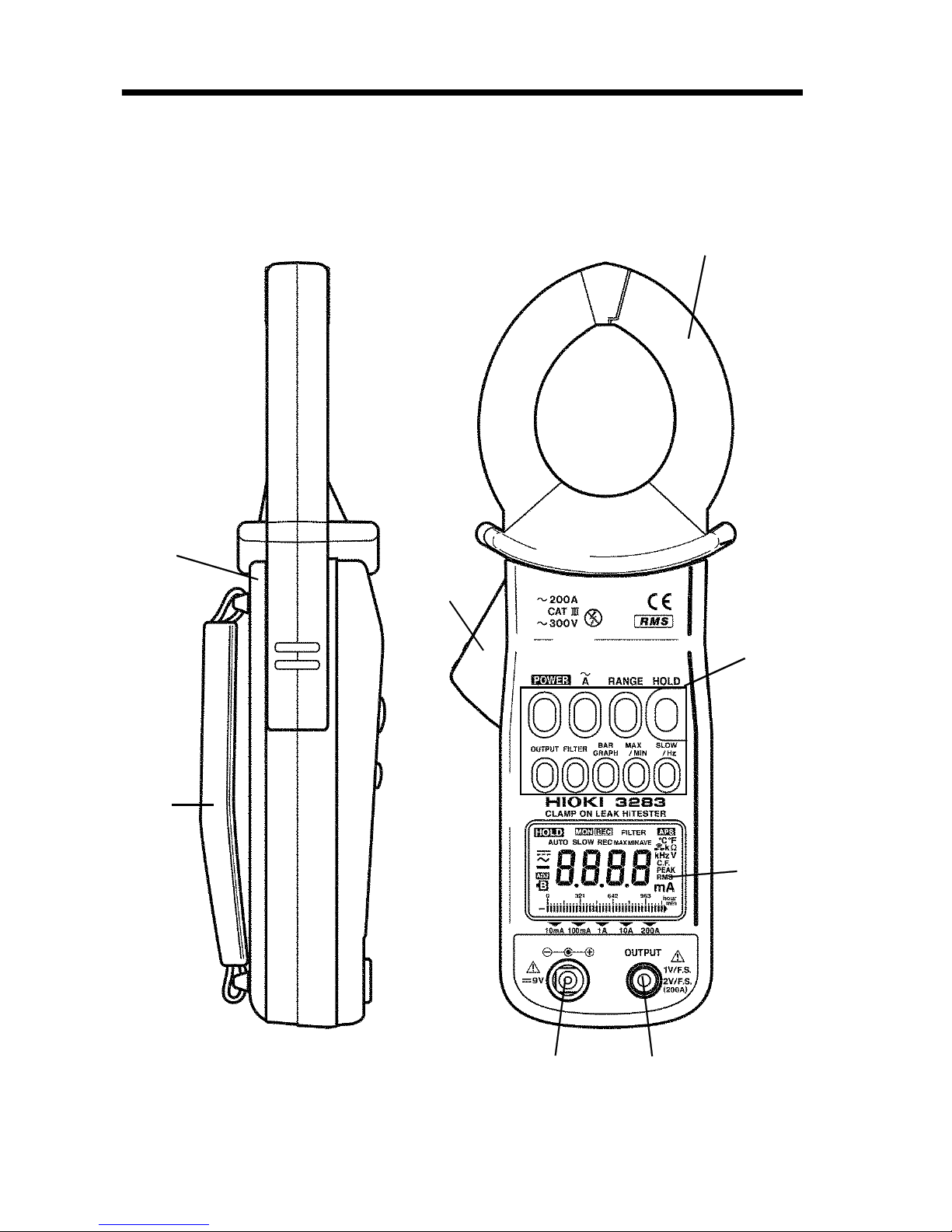
Top and Side View
1
2
3
4
5
6
7
8
1.3 Parts and Functions
Page 21

17
__________________________________________________
Chapter 1 Product Outline
_____________________________________________
1. Clamp sensor
2. Operation lever
3. Key switches
4. Display (LCD)
5. Output jack
6. AC adapter jack
7. Rear cover
8. Hand Strap
Page 22

18
__________________________________________________
Chapter 1 Product Outline
_____________________________________________
AC
AUTO
Auto-range
SLOW
Update display once every 3 seconds
REC
Record function
MAX
Maximum value
MIN
Minimum value
AVE
Average value = (maximum value +
minimum value/2)
min
1 minute/segment (bar graph)
hour
1 hour/segment (bar graph)
HOLD
Data hold function
APS
Auto power off function
MON
Waveform output (AC) is active
REC
Recording output (DC) is active
FILTER
Filter function is active
Hz
Frequency
A, mA
current
RMS
True root mean square value
Input over (bar graph)
Battery low warning
Page 23

19
__________________________________________________
Chapter 2 Measurement Procedure
_____________________________________________
Fresh battery
Battery capacity 50%
Battery capacity 0
Beep tone sounds 3 times
Chapter 2
Measurement Procedure
2.1 Preparations
1. Remove the rear cover and insert the battery.
(Refer to "Chapter 3 Battery Replacement".)
2. Press the
POWER
key to turn the unit on.
Verify that all segments of the display light up
briefly. Then the model name is shown, and the
bar graph indicates the battery condition for a
second.
3. The AC current measurement mode is activated
【 Battery low voltage power-off】
After the mark lights and battery voltage
drops below a certain level, for the inside
memory protection, the power goes off
automatically. When this occurs,
bAtt
and
Lo
are displayed.
When power goes off after display of these
marks, replace the exhausted battery with a
new one.
Page 24

20
__________________________________________________
Chapter 2 Measurement Procedure
_____________________________________________
single-phase 3-lead circuits
Transformer
b
clamp all three leads
of the circuit
b
a
Ig: leak Current
E (PE)
Load
device
Ig
2.2 Leak Current Measurement
A
1. Press the
A
key.
2. Clamp the tester on the conductor, so that the
conductor passes through the center of the
clamp sensor. For measurement of grounded
leads, clamp the tester on one lead only (see
a). For overall measurements, clamp the tester
on the entire circuit path (see B).
Page 25

21
__________________________________________________
Chapter 2 Measurement Procedure
_____________________________________________
three-phase 3-lead
circuits
b
clamp all three leads of the circuit
b
E (PE)
a
Ig
a
PE
Load
device
NOTE
For measurement of single-phase 2-lead
circuits, clamp both leads of the circuit.
For measurement of three-phase 4-lead
circuits, clamp all four leads of the circuit. If
this is not possible, the measurement can also
be carried out on the ground lead of the
equipment.
Page 26

22
__________________________________________________
Chapter 2 Measurement Procedure
_____________________________________________
NOTE
Do not input current that exceeds the
maximum continuous input of the electric
current range.
Measurement may not be accurate in the
cases below.
(1) When there is large current (of about 100
A) flowing through a nearby electric line
(2) When using the 3283 to measure special
waveforms, such as those on the secondary
side of an inverter
Note that a value of several tens of amperes
may be displayed when opening or closing the
clamp sensor, or when changing the electric
current range. This is not an error. It may take
some time for the display to return to zero.
However, starting measurement before the
display returns to zero will not affect
measurement.
3. The effective value (
RMS
) of the leak current is
shown on the digital display. The selected
current range is shown at the bottom of the
display.
Page 27

23
__________________________________________________
Chapter 2 Measurement Procedure
_____________________________________________
b
b′
a
Ig
c
c′
A
B
single-phase 3-lead
circuits
Load
device
Load
device
E (PE)
【Checking for insulation faults】
Normally, for a E (PE) grounding installation of
a transformer, the measurement will first be
made to check for overall circuit leak current in
the ground lead (a). Current changes can be
used to diagnose the leak current condition.
When leak current has been detected, the
measurement should proceed from the power
source towards the load, using overall
measurement.
1. If an insulation fault in the wiring has occurred
at position A in the illustration, leak current will
be detected at position b using overall
measurement, but not at position b'.
2. If an insulation fault in the load equipment has
occurred at position B in the illustration, leak
current will be detected at position c using
overall measurement, but not at position c'.
3. For detection of intermittent leak current
conditions (such as only when a certain piece of
equipment is operating), the use of a level
recorder will be helpful.
Page 28

24
__________________________________________________
Chapter 2 Measurement Procedure
_____________________________________________
SLOW→Hz→RMS
NOTE
The update speed cannot be changed for
frequency display.
RMS value display→Current range display
NOTE
The flashing segment indicates the full-scale
position.
【Range switching】
Each push of the
RANGE
key switches the
range in the order 10 mA → 100 mA → 1A→
10 A → 200 A →
AUTO
.
【Changing the display characteristics SLOW】
If the indicated current value fluctuates rapidly
and is hard to read, you can select a slower
update rate (once every 3 seconds) by pressing
the
SLOW/Hz
key.
The key cycles through the following modes:
【Bar graph display BAR GRAPH】
The current range display can be switched to
bar graph operation. The bar graph shows the
rms value of the measured current.
The bar graph display refresh rate is "FAST" (4
times per second).
1. Press the
BAR GRAPH
key.
2. The current range display is switched to bar
graph operation.
Each push of the
BAR GRAPH
key toggles
between the following modes:
Page 29

25
__________________________________________________
Chapter 2 Measurement Procedure
_____________________________________________
NOTE
There is no frequency output function.
Enable the filter function (see 2.3) when
conducting measurement in the cases below.
(1) When meaningless data is displayed due to
noise
(2) When using the 3283 to measure special
waveforms, such as those on the
secondary side of an inverter
The 3283 may not be able to perform
measurement in the cases below.
(1) When using input current that is 1/10 or
less of the full electric current range
(2) When measuring high frequencies with the
filter function enabled
The range display (
AUTO
and Bar graph)
indicates the electric current range.
SLOW→Hz→RMS
【Frequency (Hz) display】
1. While the display is switched to
SLOW
mode,
press the
SLOW/Hz
key.
2. The frequency of the measured current is
displayed.
If there is no input, and input is lower than
30Hz, "----" is shown.
Each push of the
SLOW/Hz
key cycles
through the following modes:
Page 30

26
__________________________________________________
Chapter 2 Measurement Procedure
_____________________________________________
X
NOTE
The frequency of special waveforms such as
at the secondary side of an inverter may not
be indicated correctly.
Depending on the magnitude and frequency of
the input current, resonances may be heard
from the clamp jaw. This does not affect the
measurement.
When the size of input current is unknown,
begin measurement with the 200 A range (filter
function is invalid) selected .
Do not input a current which exceeds the
maximum continuous input rating of the current
range.
【Load current measurement】
Be sure to clamp only one lead of the
conductor.
Page 31

27
__________________________________________________
Chapter 2 Measurement Procedure
_____________________________________________
output rate:1 V/10 mA
A
m
p
l
i
t
u
d
e
[
d
B
,
0
d
B
=
1
V
]
Frequency [Hz]
MON output frequency bandwidth (example: 10 mA range)
NOTE
The effect of the filter function is reflected in
numeric data output and waveform output.
2.3 Filter Function FILTER
The widespread use of switching power supplies
and equipment incorporating inverter technology
can cause harmonics to be superimposed on
the leak current waveform.
1. Press the
FILTER
key. The
FILTER
indication
appears. The integrated low-pass filter is now
active, cutting off unwanted higher-frequency
components.
2. Pressing the
FILTER
key once more turns the
low- pass filter off, allowing measurement of
leak current including any high-frequency
components. The
FILTER
indication disappears.
Page 32

28
__________________________________________________
Chapter 2 Measurement Procedure
_____________________________________________
NOTE
Pressing the
MAX/MIN
key during auto-
ranging (
AUTO
) fixes the range at the current
setting.
2.4 Data Hold Function HOLD
2.5 Recording Function REC
This function allows freezing the display at any
desired point for easy reading.
1. Press the
HOLD
key. The
HOLD
indication
appears on the display and the digital display
value is maintained.
To cancel the data hold function, press the
HOLD
key again.
The recording function can be used to display
the maximum display value, minimum display
value, maximum/minimum average, and the
instantaneous value.
1. Press the
RANGE
key to select the current
measurement range.
2. Press the
MAX/MIN
key while measuring
current with the conductor clamped. The
REC
indication flashes and the maximum, minimum,
or average value for the period starting when
the key was pressed to the present point can be
displayed. The instantaneous value can also be
displayed. Only one of these values can be
shown at any one time, but the other values are
kept in memory.
Page 33

29
__________________________________________________
Chapter 2 Measurement Procedure
_____________________________________________
MAX→MIN→AVE→instantaneous value
(no indication)
3. During measurement, the MAX/MIN key can
be used to select the value that should be
shown.
MAX: Maximum value is shown.
MIN: Minimum value is shown.
AVE: Average value is shown = (maximum
value + minimum value)/2
If none of the MAX, MIN,orAVE indicators is
shown, the display shows the instantaneous
value.
4. Pressing the HOLD
key will stop the recording
function. The HOLD indication appears and the
REC indication stops flashing.
By pressing the MAX/MIN
key in this
condition, the MAX, MIN, and AVE values
stored in the internal memory can be called up
on the display, as follows.
While HOLD is shown, the elapsed time is not
incremented. Also if the clamp sensor is
removed from the conductor for easier reading,
the minimum value will not return to zero.
Pressing the HOLD
key once more causes the
HOLD indication to go out. The recording
function resumes, and REC flashes again.
Page 34

30
__________________________________________________
Chapter 2 Measurement Procedure
_____________________________________________
NOTE
Momentary power loss and power surges
cannot be detected.
When the unit is turned off, accumulated data
are lost.
The maximum recording duration depends on
the remaining battery capacity.
The lowest possible frequency that can be
displayed is 30.0 Hz.
If the measurement object was clamped after
activating the recording function, the minimum
value is always zero. To prevent this, clamp
the conductor first and the press the
MAX/MIN
key to activate the recording
function.
If the clamp sensor is removed from the
measurement object while the recording
function is active, the minimum value will
become zero. To prevent this, press the
HOLD
key before removing the clamp
sensor.
To turn off the recording function, press
A
key. The maximum value, minimum value,
and average value are cleared.
Page 35

31
__________________________________________________
Chapter 2 Measurement Procedure
_____________________________________________
rms value → elapsed time → elapsed time → current range
(instantaneous value) (hours) (minutes)
【
Bar graph indication BAR GRAPH
】
The bar graph display can be changed. It is
also possible to display the current range,
effective (rms) value of the measured current,
and the elapsed time (hours and minutes).
1. Press the BAR GRAPH
key.
2. The current range display switches to bar graph
indication.
Each push of the BAR GRAPH
key cycles
through the following modes:
When the elapsed time display is activated, the
bar graph segments flash and the elapsed time
from the point when the MAX/MIN
key was
pressed is displayed.
When "min" is shown in the right-hand corner
of the bar graph, each segment of the bar graph
corresponds to one minute. Every time one
minute elapses, one segment of the flashing
bar graph goes on. When all segments on the
bar graph go on, the elapsed time is 30
minutes.
When the elapsed time exceeds 30 minutes,
one segment of the flashing bar graph goes off
every time one minute elapses.
Page 36

32
__________________________________________________
Chapter 2 Measurement Procedure
_____________________________________________
When the segments left of a flashing segment
remain on: the number of "on" segments
represents the elapsed time (0 to 29).
The illustration below shows when 20 minutes
have elapsed:
When the segments right of a flashing segment
remain on: the number of "off" segments (+30)
represents the elapsed time (30 to 59).
The illustration below shows when 50 minutes
have elapsed:
When "hour" is selected, one segment
corresponds to one hour, and the maximum
length of time that can be displayed is 59 hours.
The illustration below shows indication when 1
hour 40 minutes have elapsed.
Page 37

33
__________________________________________________
Chapter 2 Measurement Procedure
_____________________________________________
2.6 Auto Power-Off Function
APS
2.7 Battery Low Warning
2.8 Beep Tone
When APS is displayed, the auto power-off
function is active.
If no key is pressed for about 10 minutes, the
unit turns itself off automatically.
Immediately before turning off, the APS
indication flashes and a beep tone is heard for
about 30 seconds.
Pressing any key except the POWER key will
extend the powered state for another 10
minutes.
To disable the auto power-off function, hold
down the HOLD
key while turning the unit on
by pressing the POWER key. The APS
indication then is not shown.
While using the recording function or the output
function of the unit, auto power-off is disabled.
When this indication appears, the battery is
exhausted and correct measurement is not
assured. Replace the battery as early as
possible.
Refer to "Chapter 2【Battery low voltage poweroff】".
To disable the beep tone, hold down the
RANGE
key while turning the unit on by
pressing the POWER key.
Page 38

34
__________________________________________________
Chapter 2 Measurement Procedure
_____________________________________________
NOTE
If SLOW is selected while the unit is in fast
mode, the display update rate will be normal (2
times per second).
NOTE
Circuit time constant 200 ms MAX.
2.9 Fast Mode
The display update rate can be set to 4 times
per second. This is useful for example to
measure load currents with frequent variations
and similar applications.
1. Press the
A
key twice in succession.
The indication "F" is briefly shown, and the unit
switches to fast mode. From now on, the
indication "F" will appear every time the
A
key
is pressed.To cancel the fast mode, press
the
A
key twice in succession.
【
Example to measure load currents with
frequent variations
】
1. Press the
A
key twice in succession to
activate fast mode.
2. Press the RANGE key to set the current range
to a fixed setting.
When the drive current is unknown, begin
measurement with the 200 A range selected
3. Use the recording function to record the
maximum value, for easier reading.
Page 39

35
__________________________________________________
Chapter 2 Measurement Procedure
_____________________________________________
REC
(recording output) → MON(waveform output) → out
(auto power-off disabled) (auto power-off disabled) (auto power-off enabled)
2.10 Output Function OUTPUT
The output type is indicated by the
REC
(recording output, DC) or
MON
(waveform
output, AC) indication.
An output signal corresponding to the measured
value can be obtained from the unit. The output
voltage (AC/DC) normally is 1 V for the fullscale count (1000). In the 200 A range, the
output voltage (AC/DC) is 2 V for the full-scale
count (2000).
1. Press the
RANGE
key to set the current range
to a fixed setting.
2. Press the
OUTPUT
key so that the
REC
indication appears. The output function is now
active.
Auto power-off is disabled. (The
APS
indication
goes out.)
Each push of the
OUTPUT
key cycles through
the following modes:
Page 40

36
__________________________________________________
Chapter 2 Measurement Procedure
_____________________________________________
【Output rate】
MON
(waveform output : AC)
REC
(recording output : DC)
Current
Range
Output rate Accuracy
Crest
Factor
10 mA AC/DC 1 V/10 mA
AC/DC:
3.0% rdg. 10 mV
(40Hz to 2 kHz)
2.5 or less
100 mA AC/DC 1 V/100 mA
1 A AC/DC 1 V/1 A
10 A AC/DC 1 V/10 A
200 A AC/DC 2 V/200 A 1.5or less
【Output response】
REC MON
(Circuit time constant)
200 ms or less
frequency bandwidth
(-3 dB) 5 Hz to 15 kHz
Page 41

37
__________________________________________________
Chapter 2 Measurement Procedure
_____________________________________________
NOTE
To use the output function, be sure to push the
OUTPUT
key so that either
REC
or
MON
is
shown.
There is no frequency output function.
The filter function can be used to cut unwanted
high- frequency components.
If the
OUTPUT
key is pressed while auto-
range (
AUTO
) is enabled, the range is fixed at
the current setting (
AUTO
indication goes out).
For connection to a level recorder, use the
separately available 9094 OUTPUT CORD.
Use a high-impedance input device (e.g.,
recorder) for receiving output. (We recommend
a device with input impedance of at least 100
kΩ.)
NOTE
Even if the AC adapter is connected, if the
battery is exhausted (the mark lights), the
power may turn off in order to preserve the
data in the internal memory. To continue using
the instrument, replace the depleted battery
with a new battery, or remove the battery
completely.
When the AC adapter is used and there is a
high amount of noise in the power line, the
display may show several counts or noise may
be present in the output. In such a case,
connect the ground terminal of the level
recorder or the L side of the input to ground.
Pressing the
HOLD
key does not hold the
output signal.
Please note that the output signal is available
also when
REC
and
MON
indications are out,
but the auto power-off function is enabled.
【Using AC Adapter】
For long-term recordings, use the AC adapter (option).
Page 42

38
__________________________________________________
Chapter 2 Measurement Procedure
_____________________________________________
Page 43

39
__________________________________________________
Chapter 3 Battery Replacement
_____________________________________________
CAUTION
Do not fix the back casing screws too tightly.
The torque about 0.5N・m is recommended.
NOTE
Fix the terminals of battery snap and battery
exactly.
Chapter 3
Battery Replacement
1. Remove the two fastening screws of the rear
cover, using a Phillips screwdriver.
2. Remove the rear cover.
3. Remove the old battery without pulling the
codes of the snap.
4. Securely connect the battery to the battery
snap.
5. Replace the rear cover and tighten the fastening
screws.
Page 44

40
__________________________________________________
Chapter 3 Battery Replacement
_____________________________________________
Page 45

41
__________________________________________________
Chapter 4 Attaching the Hand Strap
_____________________________________________
Chapter 4
Attaching
the Hand Strap
Explains how to attach the hand strap, for easy
handling of the unit in the field.
Page 46

42
__________________________________________________
Chapter 4 Attaching the Hand Strap
_____________________________________________
Page 47

43
__________________________________________________
Chapter 5 Specifications
_____________________________________________
Chapter 5
Specifications
5.1 Measurement Specifications
Temperature and humidity for guaranteed
accuracy:
23 5 (73 9), 80% RH or
less
Guaranteed accuracy period:
1 year, or
opening and closing of the Clamp Sensor
10,000 times, whichever comes first
Page 48

44
__________________________________________________
Chapter 5 Specifications
_____________________________________________
Current Range
(Accuracy
Range)
Resolution
Accuracy
(NOTE)
(%rdg.+dgt.)
Maximum
permitted
current
10 mA
(1.00 to 10.00 mA)
0.01 mA
45 to 66 Hz:
(1.0%+5)
40 to 45
66 to 2 kHz:
(2.0%+5)
20 Arms
AC,
continuous
(see fig. A)
100 mA
(10.0 to 100.0 mA)
0.1 mA
1A
(0.100 to 1.000 A)
0.001 A
10 A
(1.00 to 10.00 A)
0.01 A
200 A
(10.0 to 200.0 A)
0.1 A
45 to 66 Hz:
(1.5%+5)
40 to 45
66 to 2 kHz:
(2.0%+5)
200 Arms
AC,
continuous
(see fig. A)
NOTE
Accuracy with filter function disabled.
When the filter function is enabled.
10 mA Range to 10 A Range:
50 Hz to 60 Hz (1.5%+5)
200 A Range: 50 Hz to 60 Hz (2.0%+5)
5.1.1 AC current Arms(true rms indication)
Page 49

45
__________________________________________________
Chapter 5 Specifications
_____________________________________________
Effect of conductor
position
within 0.1%
(in any direction from clamp sensor
center)
100 A MAX: within 0.5%
Effect of external
magnetic fields
AC 400 A/m corresponds to 5 mA,
max. 7.5 mA
Maximum rated
voltage to earth
max. 300 V rms AC (insulated
conductor)
Frequency [Hz]
C
u
r
r
e
n
t
[
A
]
Fig.A Frequency-dependent deletion characteristics
Frequency Range
(Accuracy Range)
Resolution
Accuracy
(%rdg.+dgt.)
100 Hz
(30.0 to 99.9 Hz)
0.1 Hz (0.3%+1)
1000 Hz
(95 to 1000 Hz)
1Hz (1.0%+1)
NOTE
The frequency range is automatically specified.
5.1.2 Frequency Hz
Page 50

46
__________________________________________________
Chapter 5 Specifications
_____________________________________________
Functions
Recording
Maximum (MAX), minimum (MIN),
average (AVE) value display
selectable for AC current and
frequency measurement
Data hold
Data hold function
Auto power-off
Automatic shutdown after 10.5 1
minutes. Beep tone warning.
Extension and disabling possible.
Battery low voltage
power-off
When the battery voltage falls below
a certain level, the function shuts
down the unit to prevent
malfunctions.
Beep tone
ON/OFF
Display
LCD panel
Digital indication
2000 counts
Bar graph indication
35 segments
Current range display or rms display
selectable
Over-range
indication
"
O.L.
" (bar graph)
Over range warning sound (buzzer)
Battery low warning
Battery low voltage
power-off
"
bAtt Lo
"
(7 segments used)Power turned off
after display
5.2 General Specifications
Page 51

47
__________________________________________________
Chapter 5 Specifications
_____________________________________________
Data hold indication
HOLD
Auto power-off
indication
APS
Filter function
Cutoff frequency 180 Hz 30 Hz
(-3 dB)
Display update rate
Digital indication
NORMAL: 500 ms 25 ms
(approx. 2 times/second)
SLOW : 3 s 0.15 s
(approx. 1 time/3seconds)
FAST : 250 ms 12.5 ms
(approx. 4 times/second)
Bar graph indication
FAST only
Display response
time
2.2 s max.
Range switching
Auto range, manual (fixed) range
(selectable). Frequency
measurement with auto-range only.
Output function
REC (recording output),
MON (waveform output) (selectable)
Output rate
REC : 1 V DC at full-scale point
(In the 200 A range only, 2
VDC/f.s.)
MON : 1 V AC at full-scale point
(In the 200 A range only, 2
VAC/f.s.)
Output Accuracy
3.0%rdg. 10 mV (40 to 2 kHz)
Output response
REC (DC) : circuit time constant 200
ms max.
MON (AC) : frequency bandwidth
(-3 dB) 5 Hz to 15 kHz
Output impedance
200Ω max.
Page 52

48
__________________________________________________
Chapter 5 Specifications
_____________________________________________
Circuit dynamic
characteristics
(crest factor)
2.5 max. (1.5 for 200 A range)
Withstand voltage
Chassis - clamp core: 3536 Vrms AC
for 15 seconds
Insulation
resistance
Clamp core - circuitry: 630 kilohms
min.
Location for use
Indoor, altitude up to 2000 m
Applicable
standards
Safety:
EN 61010-1:2001
Voltage input: Pollution level
2, Measurement categories
Ⅲ
(expected transient
overvoltage: 4000 V)
EN 61010-2-032:2002
Type B current sensor
EN 60529:1991 IP40
(protected against access to
hazardous parts with a wire)
EMC:
EN 61326:1997+A1:1998+
A2:2001+A3:2003
EN 61000-3-2:2000
EN 61000-3-3:1995+A1:2001
Maximum
conductor diameter
for measurement
φ40 mm max.
Operating
temperature and
humidity range
0to40 , 80%RH or less
(no condensation)
Temperature
characteristics
In 0 to 40 range: 0.05 x accuracy
specifications/
Storage
temperature
range
-10 to 50 (no condensation)
Page 53

49
__________________________________________________
Chapter 5 Specifications
_____________________________________________
Power source
One 6F22 (006P) 9 V battery or
9445-02 AC ADAPTER
(SA10-0910N, SINO-AMERICAN) or
9445-03 AC ADAPTER (EU) (SA100910G, SINO-AMERICAN) (option)
Maximum power
consumption
100 mVA
Battery life
approx. 40 hours
(continuous, no load)
External
dimensions
approx. 62W x 225H x 39D mm
Mass
approx. 400 g
Accessories
9399 CARRYING CASE 1
Hand Strap 1
Battery: 6F22(006P) 1
Instruction manual 1
Options
9445-02 AC ADAPTER
(SA10-0910N, SINO-AMERICAN)
9445-03 AC ADAPTER (EU)
(SA10-0910G, SINO-AMERICAN)
9094 OUTPUT CORD
Page 54

50
__________________________________________________
Chapter 5 Specifications
_____________________________________________
Page 55

51
__________________________________________________
Chapter 6 Troubleshooting
_____________________________________________
Problem Cause Action
Problems related to the power supply
Power will not
turn on
Power shuts
off during
operation
The battery may
be low or
depleted
Replace it with a
new battery
The battery snap
terminal may be
deformed,
causing contact
failure
Remove the
battery, then use
radio pliers to
straighten the
battery snap
terminal
When the AC
adapter is used,
power is only
supplied through
the AC adapter
When using the
battery,
disconnect the
AC adapter.
Insert the AC
adapter into the
AC outlet
lights
lights,
followed by
immediate
power
shutdown
The battery may
be low or
depleted
Replace it with a
new battery
Chapter 6
Troubleshooting
If the unit seems not to be working normally,
check the following points first before requesting
service.
Page 56

52
__________________________________________________
Chapter 6 Troubleshooting
_____________________________________________
Problem Cause Action
Problems related to display
An error
between E.001
and E.005 or
E.100 is
displayed.
Internal memory
may be
damaged
Request repair
Problems related to the clamp sensor
The clamp
sensor
generates a
sound during
measurement
When large
current or highfrequency
current is
measured,
resonance may
occur,
generating a
sound
Reclamp the
conductor.
Measure microcurrent or lowfrequency
current to
determine
whether a sound
is generated
Page 57

53
__________________________________________________
Chapter 6 Troubleshooting
_____________________________________________
Problem Cause Action
Problems related to output function
The output
rate differs
from the
specification
The output is
too low
The 200 A range
is used
Check the
electric current
range. Unlike
other ranges, the
full scale of the
200 A range is 2
V/fs
The input
impedance of
the device used
to receive output
is too low
Check the input
impedance of
the device used
to receive
output. We
recommend
input impedance
of at least 100
kΩ
MON output is
used for
measurement at
high frequency
The guaranteed
range of
accuracy is 40
Hz to 2 kHz. The
specified
frequency band
of 5 Hz to 15 Hz
is a -3 dB band.
At 15 kHz, the
amplitude is
reduced to
approximately
70%
Page 58

54
__________________________________________________
Chapter 6 Troubleshooting
_____________________________________________
Page 59

55
__________________________________________________
Chapter 7 Service
_____________________________________________
Chapter 7
Service
To clean the product, wipe it gently with a soft
cloth moistened with water or mild detergent.
Never use solvents such as benzene, alcohol,
acetone, ether, ketones, thinners or gasoline,
as they can deform and discolor the case.
The minimum stocking period for replacement
parts is five years after end of production.
For information regarding service, please
contact your dealer or the nearest HIOKI
representative.
If the unit is not functioning properly, check
the battery. If a problem is found, contact
your dealer or HIOKI representative. Pack
the unit carefully so that it will not be
damaged during transport, and write a
detailed description of the problem. HIOKI
cannot bear any responsibility for damage
that occurs during shipment.
Page 60

56
__________________________________________________
Chapter 7 Service
_____________________________________________
Page 61

Page 62

Page 63

HIOKI 3283 CLAMP ON LEAK HiTESTER
Instruction Manual
Publication date: September 2006 Revised edition 13
Edited and published by HIOKI E.E. CORPORATION
Technical Sales Support Section
All inquiries to International Sales and Marketing
Department
81 Koizumi, Ueda, Nagano, 386-1192, Japan
TEL: +81-268-28-0562 / FAX: +81-268-28-0568
E-mail: os-com@hioki.co.jp
URL http://www.hioki.co.jp/
Printed in Japan 3283A981-08
・
All reasonable care has been taken in the production of
this manual, but if you find any points which are
unclear or in error, please contact your supplier or the
International Sales and Marketing Department at HIOKI
headquarters.
・
In the interests of product development, the contents of
this manual are subject to revision without prior notice.
・
Unauthorized reproduction or copying of this manual is
prohibited.
Page 64

HEAD OFFICE
81 Koizumi, Ueda, Nagano 386-1192, Japan
TEL +81-268-28-0562 / FAX +81-268-28-0568
E-mail: os-com@hioki.co.jp/
URL http://www.hioki.co.jp/
HIOKI USA CORPORATION
6 Corporate Drive, Cranbury, NJ 08512, USA
TEL +1-609-409-9109 / FAX +1-609-409-9108
3283A980-13 06-09H
Printed on recycled paper
 Loading...