

Page 1
3281, 3282
DIGITAL CLAMP ON HiTESTER
Instruction Manual
EN
Sept. 2015 Revised edition 19
Warranty
Warranty malfunctions occurring under conditions of normal use in conformity
with the Instruction Manual and Product Precautionary Markings will be
repaired free of charge. This warranty is valid for a period of one (1) year
from the date of purchase. Please contact the distributor from which you
purchased the product for further information on warranty provisions.
Introduction
Thank you for purchasing the HIOKI "HIOKI 3281, 3282 Digital Clamp-on
HiTester". To obtain maximum performance from the instrument, please read
this manual first, and keep it handy for future reference.
Inspection
When you receive the instrument, inspect it carefully to ensure that no
damage occurred during shipping. In particular, check the accessories, panel
switches, and connectors. If damage is evident, or if it fails to operate
according to the specifications, contact your dealer or Hioki representative.
Safety
This manual contains information and warnings essential for safe operation of
the instrument and for maintaining it in safe operating condition. Before
using the instrument, be sure to carefully read the following safety notes.
The following symbols in this manual indicate the relative importance of
cautions and warnings.
DANGER
WARNING
CAUTION
NOTE
Safety Symbols
Printed in Japan
3281A981-19 15-09H
Indicates that incorrect operation presents an extreme hazard that
could result in serious injury or death to the user.
Indicates that incorrect operation presents a significant hazard that
could result in serious injury or death to the user.
Indicates that incorrect operation presents a possibility of injury to the
user or damage to the instrument.
Advisory items related to performance or correct operation of the
instrument.
The symbol printed on the instrument indicates that the user should refer
to a corresponding topic in the manual (marked with the
using the relevant function.
In the manual, the symbol indicates particularly important information that
the user should read before using the instrument.
Indicates that dangerous voltage may be present at this terminal
Indicates a double-insulated device.
Indicates DC (Direct Current).
Indicates AC (Alternating Current).
Indicates a grounding terminal.
Indicates that the instrument may be connected to or disconnected from a live
circuit.
symbol) before
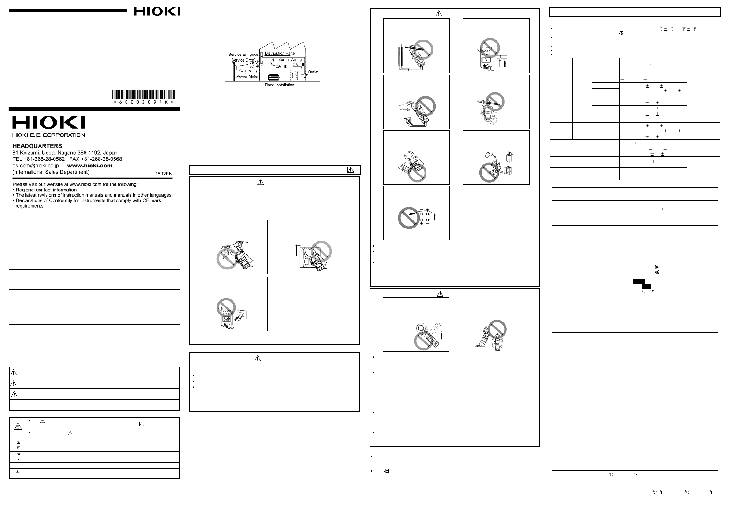
Measurement categories
This instrument conforms to the safety requirements for CAT III(3281), CAT
IV(3282) measurement instruments. To ensure safe operation of
measurement instruments, IEC 61010 establishes safety standards for
various electrical environments, categorized as CAT II to CAT IV, and called
measurement categories. These are defined as follows.
CAT II: Primary electrical circuits in equipment connected to an AC electrical
outlet by a power cord (portable tools, household appliances, etc.)
CAT II covers directly measuring electrical outlet receptacles.
CAT III: Primary electrical circuits of heavy equipment (fixed installations)
connected directly to the distribution panel, and feeders from the
distribution panel to outlets.
CAT IV: The circuit from the service drop to the service entrance, and to the
power meter and primary overcurrent protection device (distribution
panel).
Using a measurement instrument in an environment designated with a
higher-numbered category than that for which the instrument is rated could
result in a severe accident, and must be carefully avoided.
Use of a measurement instrument that is not CAT-rated in CAT II to CAT IV
measurement applications could result in a severe accident, and must be
carefully avoided.
Precautions
DANGER
This instrument is designed to conform to IEC 61010 Safety Standards,
and has been thoroughly tested for safety prior to shipment. However,
mishandling during use could result in injury or death, as well as damage
to the instrument. Be certain that you understand the instructions and
precautions in the manual before use. We disclaim any responsibility for
accidents or injuries not resulting directly from instrument defects.
Do not use on the voltage
lines exceeding 600 Vrms.
Do not input voltage in the
resistance measurement,
continuity checking and temperature measurement.
Do not use on the primary
side of the breaker.
WARNING
To prevent electric shock, when measuring the voltage of a power line use
a test lead that satisfies the following criteria:
Conforms to safety standards IEC61010 or EN61010
Of measurement category III or IV
Its rated voltage is higher than the voltage to be measured
The test leads provided with this instrument conform to the safety standard
EN61010.
Use a test lead in accordance with its defined measurement category and
rated voltage.
WARNING
During current measurement, do not connect the
test leads or temperature
probe to the instrument.
Avoid touching the exposed
metallic parts of the jaw
while measuring voltage.
Do not use the unit with the
back casing removed.
Be sure to insert the battery
with the polarity correct.
Battery
Handle and dispose of batteries in accordance with local regulations.
To avoid electric shock when measuring live lines, wear appropriate
protective gear, such as insulated rubber gloves, boots and a safety helmet.
Before using the instrument, make sure that the insulation on the test
leads is undamaged and that no bare conductors are improperly
exposed. Using the instrument in such conditions could cause an
electric shock. Replace the test leads and probes with the specified
Hioki Model L9207-10.
Do not input voltages exceeding 600 Vrms. (1000 V
max.)
Do not use when your
hands are wet.
Do not short-circuit, recharge, disassemble or incinerate batteries.
Short-circuiting
Disassembling
CAUTION
Do not use or store the instrument where it is exposed
to direct sunlight, high temperatures, high humidity, or
condensation.
Before using the instrument the first time, verify that it operates normally
to ensure that the no damage occurred during storage or shipping. If
you find any damage, contact your dealer or Hioki representative.
Removable sleeves are attached to the metal pins at the ends of the test
leads.
To prevent a short circuit accident, be sure to use the test leads with the
sleeves attached when performing measurements in the CAT III and
CAT IV measurement categories . In the CATII environment, if the tips
of the test leads do not reach the measurement object, remove the rigid
insulating sleeve before measuring. For details on measurement
categories, see "Measurement categories" in the instruction manual.
When performing measurements with the sleeves attached, be careful to
avoid damaging the sleeves. If the sleeves are inadvertently removed
during measurement, be especially careful in handling the test leads to
avoid electric shock.
To prevent an electric shock accident, confirm that the white or red
portion (insulation layer) inside the cable is not exposed. If a color inside
the cable is exposed, do not use the cable.
NOTE
Accurate measurement may be impossible in the presence of strong magnetic
fields, such as near transformers and high-current conductors, or in the
presence of strong electromagnetic fields such as near radio transmitters.
The indicator lights up when the remaining battery capacity is low. In
this case, the instrument's reliability is not guaranteed. Replace the battery
immediately.
Do not subject the instrument to vibrations or
shocks.
Do not drop the instrument.
Specification
The 3281 and 3282 are different in the maximum range.(3281: 600 A, 3282: 1000 A)
1. Measurement specification
Temperature and humidity for guaranteed accuracy: 23 5 (73 9 ), 80% RH
or less (This is guaranteed when "
Guaranteed accuracy period:1 year, or opening and closing of the jaws 10,000 times,
whichever comes first
( ) in the current ranges: 3282
Maximum rated voltage to earth: Max. 600 Vrms
Accuracy is guaranteed for over 10% input of the range in current and voltage.
Function Mode Range Accuracy( %rdg. dgt.)
RMS
(Effective
AC current
(A)
AC voltage
(V)
Crest factor 1.00 to 5.00 10% 5
Frequency (Hz)
Resistance (Ω)
Continuity 1000 Ω Buzzer at approx. 30 Ω or less
value)
PEAK
(Peak
value)
RMS
PEAK 300/600 40 to 1 kHz: 3% 5
30.00
300.0
600(1000)
Auto-ranging As per the above range
30.0 40 to 1 kHz: 5% 5
300 40 to 1 kHz: 3% 5
600 (1000) 40 to 1 kHz: 3% 5
Auto-ranging As per the above range
300.0/600
Auto-ranging
Auto-ranging
(100.0/1000)
Auto-ranging
(1000/10.00k)
2. General specifications
Diameter of
measurable conductor
Effect of conductor
position
Effect of external
magnetic field
Functions Record (displays the maximum (MAX), minimum (MIN) and
Display LCD, digital (3000 counts), bar graph (35 segments)
Display update rate Digital display: Approx. twice per second,
Response time Current, voltage, frequency: Approx. 2.2 seconds
Range selection Auto-ranging/manual ranging (fixed range) selectable (excluding
Circuit dynamic
(Crest factor)
Dielectric strength 3281
Location for use Altitude up to 2000 m (6562 feet), Indoors
Standards
applying
Dust resistance EN 60529 IP40
Operating
temperature and
humidity range
Temperature
characteristics
3281: 33 mm dia. max. (1.3"), 3282: 46 mm dia. max. (1.8")
At any position based on the center of the jaw
3281: Within
In an external magnetic field of 400 AAC/m
3281: 1.5 A max., 3282: 0.2 A max.
average (AVE) values in the AC current, AC voltage and
frequency measurements), data hold (holds the display), autopower off (approx. 10 minutes, the buzzer alarms just before
the instrument is powered off, can be extended and released),
buzzer (can be turned on or off)
Over range display: "
Battery consumption warning: "
the accuracy is not guaranteed.)
Data hold display: "HOLD"
Auto power-off display: "APS"
Units (A, V, Hz, Ω,kΩ,
Zero suppressor: 5 counts max.
:
Temperature probes have been discontinued.
*
The temperature measurement function is no longer available
Bar graph display: approx. 4 times per second (fixed)
Resistance, continuity check: Approx. 1.1 seconds
the frequency, resistance and continuity check)
2.5 max. (600 A (3281), 1000 A (3282), 600 V range: 1.7)
Between the case and input: AC 8540 V rms /1 minute
Between the case and jaw: AC 5312 V rms /15 sec
3282
Between the case and input terminals: AC 8540 V rms /1 minute
Between the case and jaw: AC 8540 V rms /1 minute
Safety
EN 61010
3281 (current): 600 VAC (Measurement Category III)
Anticipated transient overvoltage: 6000 V, Pollution Degree 2
3281 (voltage): 600 VAC (Measurement Category IV)
Anticipated transient overvoltage: 8000 V, Pollution Degree 2
3282 (current): 600 VAC (Measurement Category IV)
Anticipated transient overvoltage: 8000 V, Pollution Degree 2
3282 (voltage): 600 VAC (Measurement Category IV)
Anticipated transient overvoltage: 8000 V, Pollution Degree 2
EN 61326
EMC
0to40 (32 to 104 ), 80% RH max. (no condensation)
0.05 x accuracy specifications/ ( )at0to40 (32 to 104 )
" mark is not lighting.)
40 to 1 kHz:
1.0%rdg. 0.7%f.s.
45 to 66 Hz: 1.0% 5
40 to 45, 66 to 1 kHz:
45 to 66 Hz: 1.0% 3
40 to 45, 66 to 1 kHz:
30 to 99.9 Hz: 0.3% 1
95 to 1000 Hz: 1% 1
10 to 10.00 kΩ: 1.5% 5
4.0%, 3282: Within 1.0%
O.L.
"or" " (bar graph input over)
*,*
SLOW: Approx. once per 3 seconds,
FAST: Approx. 4 times per second
1.5% 5
1.5% 3
" (When this mark is li ghting,
)
Muximum
permissible
input
3281:
600 AAC
continuous
1000 A max.
3282:
600 AAC
continuous
1000 AAC (5
minutes)
1700 A max.
600 VAC
continuous
1000 V max.
See the currents
and voltages
above
Open terminal
voltage:
3 VDC max.
Overload
protection:
600 Vrms
.
Page 2
Storage temperature
S
w
Square
wave
range
Power source Rated power voltage 9 VDC
Maximum rated
power
Batterylifetime Approx. 45 hours (continuous, no load)
External dimensions
and mass
3. Accessories
Model L9207-10 Test Lead (black and red set), Instruction manual, Model 9399 Carrying
Case, Hand strap, 6F22 (006P) battery
-10 to 50 (14 to 122 ) (no condensation)
6F22 layer-built manganese battery x 1
100 mVA
Approx. 62W x 216.5H x 39D mm, Approx. 350 g (3281)
Approx. 2.44"W x 8.58"H x 1.54"D, Approx. 12.3 oz. (3281)
Approx. 62W x 231H x 39D mm, Approx. 400 g (3282)
Approx. 2.44"W x 9.06"H x 1.54"D, Approx. 14.1 oz. (3282)
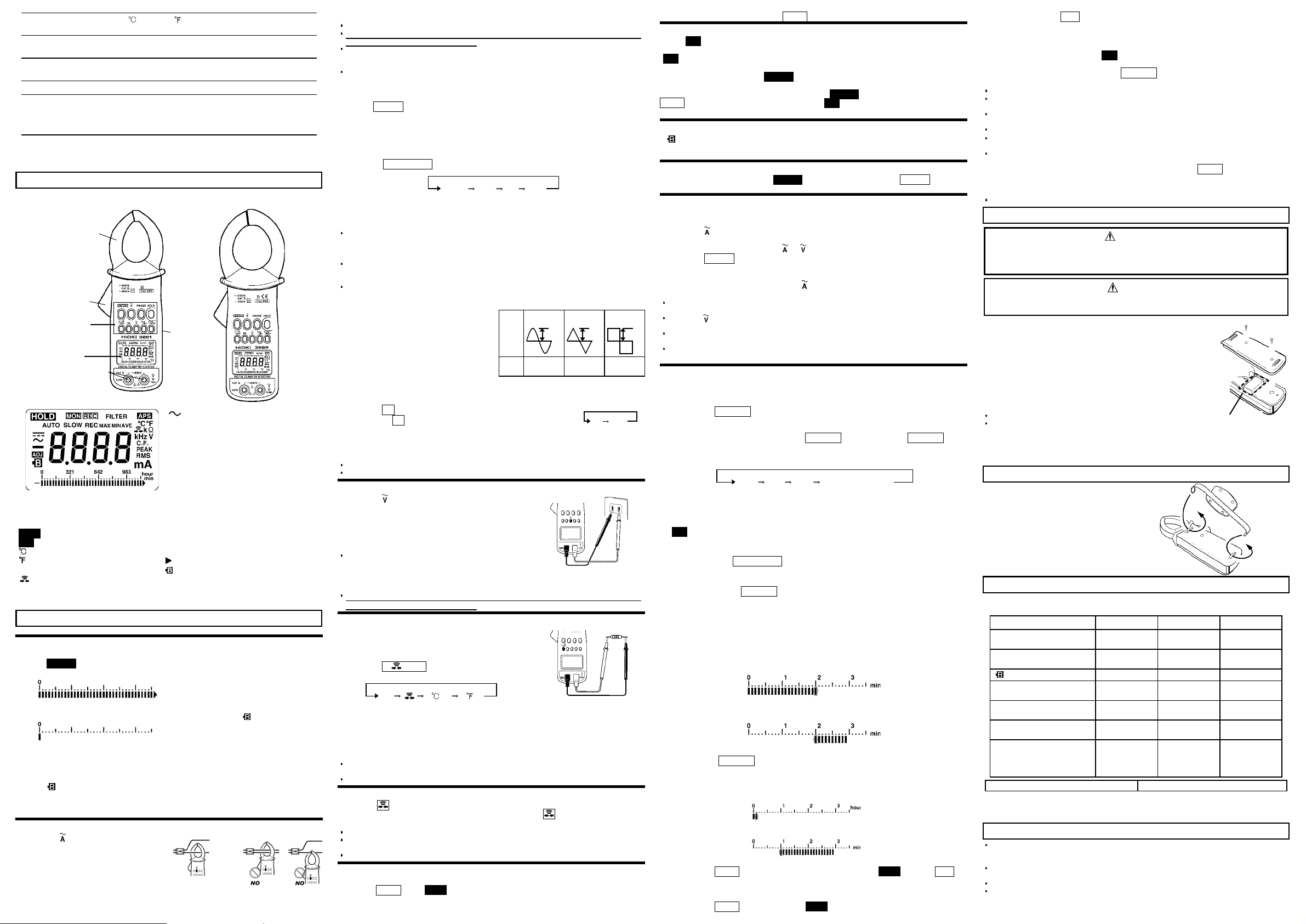
Names and Functions of Parts
3281(600 A
Jaw
Lever
Key switches
Display (LCD)
Voltagae and resistance
input terminals
min
One minute: one segment (bar
graph)
hour
One hour: one segment (bar
graph)
Data hold
HOLD
Auto power-off
APS
Centigrade
*
Fahrenheit
*
Resistance
Ω,kΩ
Continuity
: Temperature probes have been discontinued.
*
The temperature measurement function is no longer available.
)
Back casing
(back)
AUTO
SLO
REC
MAX
MIN
AVE
Hz
V
A
RMS
PEAK
C.F.
3282(1000 A
Alternating current
Auto-ranging
Display update:
approx. once per three seconds
Record function
Maximum value
Minimum value
Average value = (maximum value
+ minimum value) / 2
Frequency
Voltage
Current
True RMS value
Peak value
Crest factor = Peak value /
Effective value
Input over (bar graph)
Battery consumption warning
)
Measurement Procedure
Preparation
1. Remove the rear cover and insert a battery. (Refer to Battery Replacement Procedure.)
2. Press POWER to turn the unit on. Verify that all segments of the isplay light up briefly.
Then the model name is shown, and the bar graph indicates the battery condition.
Fresh battery
Battery capacity 0 " " light.
Beep tone sounds 3 timeshe battery
condition.
Measurements taken at this battery level
is not guaranteed for accuracy.
3. The AC current measurement mode is activated.
Low battery voltage detection function
After the mark lights and battery voltage drops below a certain level, the power goes
off automatically. When this occurs,
When power goes off after display of these marks, replace the exhausted battery with a
new one.
AC current (ACA) measurement A
1. Press the
2. Clamp only one of the conductors and
place it in the center of the jaw.
The effective value (RMS) of the current is
displayed in the digital display and bar
graph.
A suitable measurement range is selected
automatically (AUTO).
key.
bAtt
andLoare displayed.
OK
NOTE
Use data hold function when you abolish indication and want to read it.
Please note that waveforms that include elements outside the frequency characteristic
range may not be measured correctly.
Current measurements exceeding 600 A AC should be of short duration. Heat builds
up in the jaw proportionate to the current value, and will reach a dangerous level over
a long period of time.
The unit cannot read zero with no input at low temperature. Even then, the accuracy is
guaranteed when a current of 3 A or more is measured.
Range selection
Press the RANGE key repeatedly cycles through the 30 A, 300 A, 600 A (1000 A) and
AUTO
ranges.
Changing the display update SLOW
When the readings fluctuate and are difficult to take, it is possible to make the display
update slow (approx. once per three seconds), and the readings easy to take. The
screen-updating speed cannot be changed for the bar-graph display.
Pressing the SLOW/PEAK
Peak value display PEAK
The peak value is displayed. The effective value is displayed in the bar graph.
NOTE
Mode displaying the PEAK (peak value) of a continuous wave which lasts for more
than 250 ms.
To keep the displayed value, use the recording function in the PEAK display mode
(refer to recording function REC 1.).
As there is a period whereby no sampling is done on this instrument, it may not be
possible to measure an instantaneous peak current that does not reach 250 ms, such
as the motor starting current, even when the recording function is used.
To accurately measure an instantaneous peak current such as an inrush current,
please use HIOKI CM4371 and CM4373.
Crest factor display C.F.
The crest factor (peak-to-rms ratio) of a
waveform is displayed.
Crest factor = Peak value / Effective value
The crest factor of an undistorted sine wave
is 1.41.
A crest factor of other than 1.41 indicates
that a waveform is distorted, i.e., contains
harmonic components.
When a crest factor of current is displayed,
the indicator "
The effective value is displayed in the bar graph.
Frequency display Hz
1. Press the Hz key.
2. Pressing the Hz
3. The frequency of the current being measured is displayed.
When no input is applied, "
A
"
NOTE
When the frequency is lower than 30 Hz, "
The AUTO range display indicates the current range.
A
" flashes.
" flashes. The effective value is displayed in the bar graph.
key repeatedly changes the display as follows.
SLOW PEAK C.F. RMS
ine
ave
Wave
form
Peak
C.F. 1.41 1.73 1
key changes the display as shown in the figure.
----
" is displayed. When measuringthe current frequency,
----
" is displayed.
Triangular
wave
Peak
Peak
Hz RMS
AC voltage measurement V
1. Press the
2. The effective value (
the digital display and bar graph.
The display update changing, and the peak value,
crest factor and frequency displays are possible as
well as in the AC current measurement.
NOTE
Be sure to use the test leads with the sleeves
attached when performing measurements in the CAT
III and CAT IV measurement categories. In the
CATII environment, if the tips of the test leads do not
reach the measurement object, remove the rigid insulating sleeve before measuring.
Please note that waveforms that include elements outside the frequency characteristic
range may not be measured correctly.
key.
RMS
) of voltage is displayed in
Black
Red
Plug in the test leads
Resistance measurement
1. Insert the test leads in the instrument as shown in
the figure.
2. Attach or remove the rigid insulating sleeve as
required by the measurement object.
3. Press the Ω/
display as follows.
: Temperature probes have been discontinued.
*
The temperature measurement function is no longer available.
4.The resistance value is displayed in the digital display and bar graph. Ranging is
automatic (
NOTE
If a voltage is input, a warning beep will sound. Stop measurement immediately. (The
internal circuit is protected against up to AC 600 V.)
In some cases, the alarm does not beep for DC or DC weighted components.
/TEMP key to displayΩ, changes the
Ω
AUTO
).
* *
(Centigrade) (Fahrenheit)
Black
Plug in the test leads
Red
Continuity check
1. Display "
2. The buzzer beeps at less than approximately 30 Ω, and "
NOTE
The digital display indicates the measured resistance value.
If a voltage is input, a warning beep will sound. Stop measurement immediately. (The
internal circuit is protected against up to AC 600 V.)
In some cases, the alarm does not beep for DC or DC weighted components.
" in the same way as in the resistance measurement.
" flashes.
Data hold function HOLD
Data hold functions to "stop" the display at its present reading.
Press the HOLD key. "HOLD" appears, and the digital and bar graph displays are
held. This function is effective for all measurement functions and modes.
To release this function, press the HOLD
key again.
Auto power-off function APS
When "APS" is being displayed, the auto power-off function is effective.
The unit is powered off in approx. 10 minutes unless any key is pressed.
"APS" flashes and the alarm beeps for approx. 30 seconds just before the unit is
powered off.
Pressing a key other than the POWER key prolongs the auto power-off function for 10
minutes.
To release the auto power-off function, press the POWER key while holding down the
HOLD key to power on the unit. In this case, "APS" does not appear.
When using the record function, the auto power-off function is ineffective.
Battery consumption warning
If
is indicated, the battery power is running low and accuracy cannot be guaranteed.
Replace with a new battery. Refer to "Preparation" for the confirmation of the capacity of
the battery.
Buzzer
To turn off the buzzer, press the POWER key while holding down the RANGE key to
power on the instrument. The alarm and continuity buzzers cannot be turned off.
FAST mode
Make it FAST mode when you measure load currents with variations.
The digital display update can be set to approx. 4 times per second.
1. Press the
F
"
" appears for an instance, and the unit enters the FAST mode.
Then "
2. Press the RANGE
3. It is convenient for taking readings to hold the maximum value (MAX) by using the
record function.
4. To release the FAST mode, press the
NOTE
The stable measurement cannot be made unless the waveform lasts for more than
250 ms.
Press the key in the case of the voltage measurement as well after it is made FAST
mode.
This mode is not effective for the resistance, continuity and temperature
measurements.
If setting to the
in the normal mode (approx. twice per second).
key twice to set to the FAST mode.
F
" appears each time the or key is pressed.
key to fix the current range.
key twice again.
SLOW
display in the FAST mode, the display update is the same as
Recording function REC
Use the recording function to hold the maximum and minimum measured values and
maximum/minimum averages.
1. Measurement indicated value
Pressing the MAX/MIN
activates the recording function.
maximum value (MAX), minimum value (MIN), and average value (AVE) in internal
memory from the instant you press the MAX/MIN
with the recording function activated switches the display as shown below. If MAX,
MIN, or AVE is not displayed, an instantaneous value is displayed.
Data (MAX, MIN, AVE) remains saved while the display is switched. If maximum or
minimum data is updated in the meantime, however, the data values will change.
With the recordingfunction activated, the auto power-off function remains disabled.
(APS off.)
The average value (AVE) displayed is calculated by: Average Value = [(Maximum
value + Minimum Value)/2].
After pressing the SLOW/PEAK
function and select MAX. The peak hold function will be activated.
2. Display of Elapsed Time
When you press the MAX/MIN
segments flash and the elapsed time appears.
min
When "
bar graph corresponds to one minute. Every time one minute elapses, one segment
of the flashing bar graph goes on. When all segments of the bar graph go on, the
elapsed time is 30 minutes.
When the elapsed time exceeds 30 minutes, one segment of the flashing bar graph
goes off every time one minute elapses.
When the segments left of a flashing segment remain on: the number of "on"
segments represents the elapsed time (0 to 29).
The illustration below shows when 20 minutes have elapsed:
When the segments right of a flashing segment remain on: the number of "off"
segments (+30) represents the elapsed time (30 to 59).
The illustration below shows when 50 minutes have elapsed:
When digital display switches the average value (AVE) to a instantaneous value when
you press the MAX/MIN
mode, each segment of the bar graph corresponds to one hour. The way to read the
bar graph here is similar to reading it in minutes. When all bar graph segments
remain on, the elapsed time is 30 hours.
The illustration below shows when one hour, 40 minutes have elapsed.
3. Deactivation of Recording Function
Pressing the HOLD key deactivates the recording function. HOLD goes on, REC
stops flashing and goes on, and the elapsed time stops incrementing.
While the recording function is being deactivated, data are not updated, even if the
jaw is disconnected from the conductor.
Pressing the HOLD key again cancels HOLD display and activates the recording
" is shown in the right-hand corner of the bar graph, each segment of the
key during measurements of current, voltage, or frequency
REC
flashes and the instrument saves the
key. Pressing the MAX/MIN key
MAX MIN AVE Instantaneous value
key to display the peak value, activate the recording
key to activate the recording function, the bar graph
key, the right corner of the bar graph indicates hours. In this
(No display)
function again, with REC
4. Cancellation and Resetting of Recording Function
To cancel the recording function, press the related function key (A, V or Hz) for the
measurement in progress. Once the recording function is canceled, the auto poweroff function becomes effective. (APS goes on.)
To restart the unit after resetting the data, temporarily cancel the recording function,
then activate it again by pressing the MAX/MIN
Note
An instantaneous power failure and a surge cannot be detected.
The recording function is not effective for the resistance and temperature
measurements.
Use the recording function after having confirmed a battery residual quantity.
(Shown on the bar graph at power on.)
The lowest possible frequency that can be displayed is 30 Hz.
If changing the range when "
data and elapsed time are cleared.
Activate the recording function during measurement to obtain minimum value or
average value data. If the function is activated with no input, the minimum value will
remain zero. To deactivate the recording function, press the HOLD
terminate the measurement. If you disconnect the jaw or test lead from the circuit
under measurement without deactivating the recording function beforehand, the
minimum value will be zero.
When the unit is turned off, accumulated data are lost.
flashing again.
key.
O.L.
" is being displayed in any of the displays, the held
key first, and then
Battery Replacement Procedure
WARNING
When replacing the battery, be sure to insert it with the correct polarity.
Otherwise, poor performance or damage from battery leakage could result.
Replace battery only with the specified type.
CAUTION
Do not fix the back casing screws too tightly.
The torque about 0.5N・m is recommended.
1. Remove the two fastening screws of the rear cover,using a
Phillips screwdriver.
2. Remove the rear cover.
3. Remove the old battery without pulling the codes of the
snap.
4. Attach the new battery onto the battery snaps, paying
attention to the polarity, and then install the battery in the
battery holder.
5. Fasten the rear cover.
6. Screw in the fastening screws to fasten the rear cover.
Note
A 6LR61 battery is also usable.
Each of positive and negative terminals of nine-volt layeredtype dry batteries differ slightly in shape and size according
manufactures and types. When attaching the battery onto the battery snap, you may
notice them fastened each together tightly or loosely. Even then, the instrument will work
if the battery with the battery snap attached is installed properly in the battery holder.
Battery holder
How to Attach the Hand Strap
The hand strap improves the operation.
Troubleshooting
Although the instrument seems to be out of order in the following cases, there may be
the causes of the troubles. Check it again before you send it for repair.
Symptom Battery Battery snap Test leads
The instrument cannot be
powered on.
Power is cut off immediately
after it is turned on.
" " lights.
The instrument is powered
off during operation.
Voltage measurement does
not function.
Resistance measurement
does not function.
Remedy:
If the trouble cannot be
remedied, send the
instrument for repair.
An indication E.001 to E.005 appears. Send the instrument for repair.
:
When the battery is drained, the relay may be operated immediatelyafter the power
*
is turned on or when the measurement function is changed, and the power may
suddenly be cut off. Replace the battery with a new one when this arises.
*
*
- -
- -
Replace with a
new battery.
- -
- -
The terminals of
the battery snap
are poorly
contact.
-
-
Check the test
leads wiring.
Service
To clean the instrument, wipe it gently with a soft cloth moistened with water or mild
detergent. Never use solvents such as benzene, alcohol, acetone, ether, ketones,
thinners or gasoline, as they can deform and discolor the case.
The shortest period for possession of the repair parts is 5 years after stopping the
production.
For inquiries about se rvice, contact your dealer or Hioki representative.
Pack the instrument carefully so that it will not be damaged during shipment, and
include a detailed written description of the problem. Hioki cannot be responsible for
damage that occurs during shipment.
 Loading...