

Page 1
安全記号
ト
使用者は、機器上に表示されている マークのところについて、取扱説明書の マ
ークの該当箇所を参照し、機器の操作をしてください。使用者は、取扱説明書内の
マークのあるところは、必ず読み注意する必要があることを示します。
二重絶縁構造を示します。
直流(DC)を示します。
交流(AC)を示します。
3280
CLAMP ON HiTESTER
INSTRUCTION MANUAL
November 1999 Revised edition 3 Printed in Japan
3280A980-03 99-11-1N 783301503
はじめに
このたびは、HIOKI 3280 クランプオンハイテスタ をご選定いただき、誠にありがとうございま
す。この製品を十分に活用いただき、末長くご使用いただくためにも、取扱説明書はていねいに扱い、い
つも手元に置いてご使用ください。
保証について
この製品は、弊社の厳密なる検査を経てお届けしたものです。
万一ご使用中に故障が発生した場合は、お買い求め先に依頼してください。
1.本器の保証期間は購入日より3年間です。(ご購入日が不明の場合は、製品製造月から4年を目安とし
ます。)
2.取扱説明書・本体注意ラベルなどの注意事項に従った正常な使用・保管状態で保証期間内に発生し
た故障は、弊社規定により無償修理いたします。ただし、確度は除きます。
3.保証期間内でも、次の場合には有償修理となります。
・本体から取り外し可能なテストリード・プローブ・キャリングケース・コード類
・お客様で修理や改造をされた場合
・お買い上げ後の輸送や落下等による故障
・本体のきずや汚れなど外観上の変化
・火災、地震等天災地変および不可抗力での人災、事故による故障
・電池など消耗部品および取扱説明書の交換
・その他弊社の責任とみなされない故障。
点 検
本器がお手元に届きましたら、輸送中において異常または破損がないか点検してからご使用ください。万
一、破損あるいは仕様どおり動作しない場合は、お買上店(代理店)か最寄りの営業所にご連絡ください。
使用前の確認
・ 使用前には、点検と動作確認をしてください。また、リード線の被覆が破れたり、金属が露出してい
ないか確認してください。故障を確認した場合および損傷がある場合は、感電事故になるので、お買
上店(代理店)か最寄りの営業所にご連絡ください。
確度表
23℃±5℃ 80% r h 以下, ただし結露しないこと
AC 測定:平均値整流実効値指示
ファンクション レンジ 測定確度
420.0 A
ACA
[ A]
導体位置の影響:±5.0%以内(センサ中心部を基準としていかなる位置においても)
被測定回路電圧:最大 AC600 Vrm s
1000 A
ファンクション レンジ 測定確度
4.200 V
42.00 V
ACV
[ V]
DCV
[ V]
導通
*1:
入力インピーダンス
420.0 V
600 V
420.0 mV
4.200 V
42.00 V
420.0 V
600 V
420.0 Ω
4.200 kΩ
42.00 kΩ
Ω
420.0 kΩ
4.200 MΩ
42.00 MΩ
420.0 Ω
*2:
周波数範囲
±1.5% rdg. ±5 dgt. *2 50〜60 Hz
±1.5% rdg. ±5 dgt. *2 50〜60 Hz
±2.3% rdg. ±8 dgt.
*2 50〜500 Hz
±1.3% rdg. ±4 dgt.
±2.0% rdg. ±4 dgt.
±2.0% rdg. ±4 dgt.
±2.0% rdg. ±4 dgt.
±2.0% rdg. ±4 dgt.
±5.0% rdg. ±4 dgt.
±10.0% rdg. ±4 dgt.
±2.0% rdg. ±6 dgt.
*3:
開放端子電圧
5
*
*
5
*1 11 MΩ±5%
10 MΩ±5%
10 MΩ±5%
10 MΩ±5%
*1 100 MΩ以上
11 MΩ±5%
10 MΩ±5%
10 MΩ±5%
10 MΩ±5%
*3 3.4 V 以下
0.7 V typ. 3.4 V 以下
0.47 V typ. 3.4 V 以下
0.47 V typ. 3.4 V 以下
0.47 V typ. 3.4 V 以下
0.47 V typ. 3.4 V 以下
*3 3.4 V 以下
*4 50 Ω±30 Ω
*4:
しきい値
備考 最大許容入力
*5: rdg.
最大許容入力
AC2000 A 連続
AC600 Vrms
DC600 V
AC250 Vrms
AC250 Vrms
読み値、表示値
, dgt.
分解能
本取扱説明書の注意事項には重要度に応じて以下の表記をしています。
注記
仕 様
液晶表示 最大 4199 表示
オーバーレンジ表示 OF または-OF
電池消耗警告
データホールド表示
ゼロサプレス 5 カウント以下(電流測定のみ)
表示更新レート FAST 400 ms±25 ms
レンジ切換え オートレンジ/マニュアルレンジ
耐電圧 ケース−回路間 AC3.7 kV/1 分間
放射イミュニティの影響
(3V/mにて)
使用場所 高度 2000 m まで、屋内
測定可能導体径 φ33 mm 以下
使用温湿度範囲 0〜40℃, 80%rh 以下(結露しないこと)
保存温度範囲 -10〜50℃(結露しないこと)
温度特性 0〜40℃において、0.1×確度仕様/℃
電源 定格電源電圧 DC3 V×1 リチウム電池:CR2032×1
最大定格電力 15 mVA
連続使用時間 約 150 時間(無負荷)
寸 法・質 量 57(W)×175(H)×16(D) mm, 約 100 g
付属品 取扱説明書、9398 携帯用ケース、9208 テストリード
オプション 9209 テストリードホルダ
適合規格 安全性
EMC
安全について
本器を安全にご使用いただくために、また機能を十二分に活用いただくために、下記の注意事項をお守り
ください。
この機器は、IEC61010-1 安全規格に従って、設計され、試験し、安全な状態で出荷されています。
この測定器は高電圧を測定するため、測定方法を間違えると、人身事故や機器の故障につながる可能
性があります。取扱説明書を熟読し、十分に内容を理解してから操作してください。万一事故があっ
ても、弊社製品が原因である場合以外は責任を負いかねます。
注記:
ご使用にあたっての注意
直流(DC)と交流(AC)の両用を示します。
接地端子を示します。
危険
警告
注意
操作や取扱いを誤ると、使用者が死亡または重傷につながる危険性が極めて高い
ことを意味します。
操作や取扱いを誤ると、使用者が死亡または重傷につながる可能性があることを
意味します。
操作や取扱いを誤ると、使用者が傷害を負う場合、または機器を損傷する可能性が
あることを意味します。
製品性能および操作上でのアドバイス的なことを意味します。
SLOW 3.2s±0.2 s
クランプセンサ−ケース間 AC5.55 kV/1 分間
クランプセンサ−回路間 AC5.55 kV/1 分間
電流測定 レンジの 15%以下(無負荷、テストリード接続状態)
EN61010-1:1993+A2:1995
電流測定部 汚染度 2 過電圧カテゴリ (CAT)Ⅲ(予想される過渡過電圧 6000 V)
電圧測定部 汚染度 2 過電圧カテゴリ (CAT)Ⅱ(予想される過渡過電圧 4000 V)
EN61010-2-031:1994, EN61010-2-032:1995
UL3111-1:1994, UL3111-2-32:1999, CAN/CSA-C22.2No. 1010.1-92+B-97,
CAN/CSA-C22.2No. 1010.2.031-94, CAN/CSA-C22.2No. 1010.2.032-96
EN55011:1991+A1:1997+A2:1996, EN50082-1:1992
危 険
警 告
工業用電力ラインは電源電圧の数倍のスパイク状電圧を含むものがあります。このよ
うな電力ラインの測定の場合には、人身事故や電気事故につながる危険性を含んでいま
す。安全上、このテスタを250 V 以上の工業用電力ラインの電圧測定に使用しないでく
ださい。(電流測定除く)この場合には、下記適用製品をお使いください。
適用製品:3008、CATⅢ表示製品
工業用電力ラインとは、工場、ビル等の各種機器に供給している大容量電路の総称です。大容
量電路とは、目安として
ズ)、配線用しゃ断器(ブレーカ)で保護されている電路は含みません。
20 A
以上の電路です。よって、それ以下の過電流しゃ断器(ヒュー
危 険
・クランプ製品は、短絡、人身事故などを避けるために、AC600 V 以下の電路で使用してください。
・最大定格動作電圧は AC/DC600 V です。最大定格動作電圧を超えると本器を破損し、人身事故に
なるので測定しないでください。
・測定前にファンクションスイッチ の位置を確認してください。電圧レンジ以外のレンジで電圧を
測定すると、人身事故や本器の破損になります。ファンクションスイッチを切り換えるときは、被
測定物からテストリードを外してください。
・クランプセンサ、テストリードは、必ずブレーカの2 次側に接続してください。ブレーカの 2 次
側は、万一短絡があっても、ブレーカにて保護します。1 次側は、電流容量が大きく、万一短絡事
故が発生した場合、損傷が大きくなるので、測定しないでください。
警 告
・電流測定時には、電気事故を避けるため、テストリードは本体に接続しないでください。
・本器をぬらしたり、ぬれた手で測定すると感電事故になるので注意してください。
※お問い合わせは、最寄りの営業所または本社販売企画課まで。
E-mail: info@hioki.co.jp URL http://www.hioki.co.jp
1 2 3 4
・感電事故を防ぐため、活線で測定作業を行う場合は、労働安全衛生規則に定められているように、
電気用ゴム手袋、電気用ゴム長靴、安全帽等の絶縁保護具を着用してください。
・直射日光や高温、多湿、結露するような環境下での、保存や使用はしないでください。変形、絶縁
劣化を起こし、仕様を満足しなくなります。
・本器の損傷を防ぐため、運搬および取扱いの際は振動、衝撃を避けてください。特に、落下などに
よる衝撃に注意してください。本器を破損します。
・使用前には、過酷な保存や輸送による故障がないか、点検と動作確認をしてから使用してくださ
い。故障を確認した場合は、お買上店(代理店)か最寄りの営業所にご連絡ください。
・テストリード の被覆が破れたり、金属が露出していないか、使用する前に確認してください。損
傷がある場合は、感電事故になるので、指定の 9208 と交換してください。
トランスや大電流路など強磁界の発生している近く、また無線機など強電界の発生している近
注記:
くでは、正確な測定ができない場合があります。
機能と表示
オートパワーセーブ機能
・最終操作をしてから約 30 分後に、自動的にパワーセーブ状態になります。
・電源を入れると、自動的にオートパワーセーブ機能が働きます。
・オートパワーセーブ状態から復帰させたい場合は、ファンクションスイッチを1度 OFF にしてください。
オートパワーセーブ機能は解除できません。
注記:
オートレンジ機能(AUTO 点灯)
交流電流 [ A]、交流電圧 [ V]、直流電圧 [ V]、抵 抗 [Ω] 測定時は、AUTO レンジとなります。測
定レンジは自動的に最適レンジに設定されます。
マニュアルレンジ機能(AUTO 消灯)
キーを押しながら ON した場合に、交流電流 [ A]、交流電圧 [ V]、直流電圧 [ V]、抵抗 [Ω] 測定
でマニュアルレンジとなります。なお、導通テストは使用できません。Ω 、SAMP. F/S キーを押す
ことでレンジを変更できます。
HOLD キーを押しながらON マニュアルレンジで FAST 表示
Ω 、SAMP. F/S キーを押しながら ON マニュアルレンジで SLOW 表示
オーバーフロー表示
入力が測定範囲を超えた場合、表示部には"OF"または"-OF"が表示されます。
各部の名称と機能
①液晶表示部
②クランプセンサ
③レバー
④ファンクションスイッチ
OFF /
交流電圧
抵抗・導通テスト[Ω
⑤Ω 、
[ A]、[ V]、[ V]
・
表示更新(
表示値が変動して読取りにくいと
きに、表示更新を遅くして(
約1回/3秒)読取りやすくするこ
とができます。
/ ]
・[Ω
抵抗[Ω]/導通テスト
HOLD
⑥
HOLD
し、表示がホールドします。もう一
HOLD
度
ールドが解除されます。
⑦コネクタ ⑧プラグ
電圧測定、抵抗測定、導通テストを使用するとき、テストリードのプラグを本体のコネクタに接続しま
す。コネクタのキーとプラグのミゾを合わせて差し込みます。
⑨赤(+)リード ⑩黒(−)リード
[ A] /
交流電流
[ V] /
SAMP. F/S
FAST / SLOW
のとき
キー
キーを押すと が点灯
キーを押すと、表示のホ
直流電圧
/ ]
のとき
[ ]
[ V] /
キー
)切換え
SLOW:
切換え
測定方法
測定前にファンクションスイッチの位置を確認してください。ファンクションを間違えると、人身
事故や本器の破損になります。ファンクションスイッチを切り換えるときは、被測定物からテスト
リードを外してください。
交流電流測定
①ファンクションスイッチをAにします。
②導体をクランプセンサの中央にはさみ込んでくださ
い。導体は必ず1本だけクランプしてください。
インバータの2次側のような特殊な波形は、
注記:
測定できない場合があります。
電圧測定
・最大過電圧保護は AC/DC600 V です。ただし、電力ラインの場合は、AC250 Vrms です。この最
大過電圧を超えると本器を破損し、人身事故になるので測定しないでください。
・テストリードの先端で、電圧のかかっているラインを短絡すると人身事故につながり、非常に危険
です。電圧測定は十分に注意して行ってください。
・テストリードによる測定箇所は、安全のため必ずブレーカの 2 次側で行ってください。
・対地間最大定格電圧は AC/DC600 V です。大地に対して 600 V を超える電圧は測定しないでくだ
さい。本器を破損し、人身事故になります。
テストリードのプラグは、本体のコネクタに確実に装着して使用願います。
交流電圧測定
テストリードのプラグをコネクタに差し込みます。
① ファンクションスイッチを
② 測定物にリードを接続します。交流測定の場合、
+,−の接続は、関係ありません。
③ 表示部の測定値を読みます。
[
[
V
にします。
表示:
測定値
単位
記号
小数点
④
A]
V]
注 意
②
③
①
⑤
危 険
危 険
⑩
⑨
先端を測定物
③
に接続して測
定します。
⑥
⑦
⑧
電池カバー(裏)
○
①
②
×
②
③
①
コンセン
リード
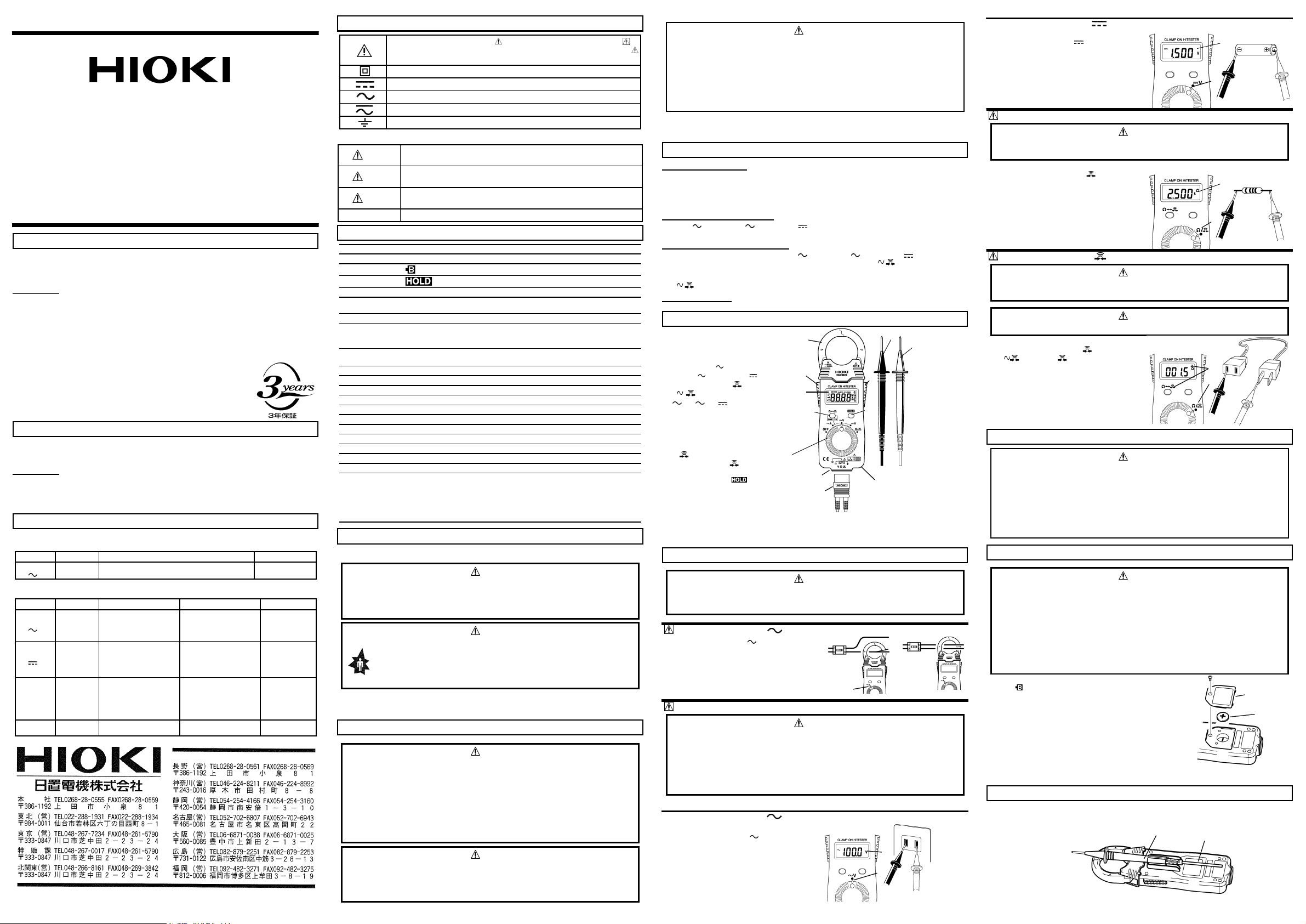
直流電圧測定
テストリードのプラグをコネクタに差し込みます。
① ファンクションスイッチを
② 測定物にリードを接続します。
③ 表示部の測定値を読みます。
注記:
抵抗測定のファンクションに、電圧を入力しないでください。
電圧を入力すると本器を破損し、人身事故になります。
テストリードのプラグをコネクタに差し込みます。
① ファンクションスイッチを Ω/にします。
② 測定物にリードを接続します。
③ 表示部の測定値を読みます。
導通テストのファンクションに、電圧を入力しないでください。
電圧を入力すると本器を破損し、人身事故になります。
電気事故防止のため、測定回路の電源を切ってから行ってください。
テストリードのプラグをコネクタに差し込みます。
① ファンクションスイッチをΩ/にします。
②Ω キーを押し
③ 測定物にリードを接続します。
導通状態では、ブザーが鳴ります。
保 守
・本器の保護機能が破損している場合は、使用できないように廃棄するか、知らないで動作させるこ
・本器の汚れをとるときは、柔らかい布に水か中性洗剤を少量含ませて、軽くふいてください。ベン
・長い間使用しないときは、電池の液漏れによる腐食を防ぐために電池を抜いて保管してください。
・故障と思われるときは、電池の消耗、テストリードの断線を確認してから、お買上店(代理店)か
電池交換
・本器が被測定物に接続していると、端子類は危険な電圧が加わっていることがあり、電池カバーを
・電池は、リチウム電池:CR2032 を使用してください。指定以外の電池を使用した場合は、電池が
・電池交換するときは極性+、−に注意し逆挿入しないように電池を入れてください。
・使用済の電池をショート、再充電、分解、火中に投入しないでください。破裂する恐れがあります。
・電池を取り出した場合、電池は幼児の手が届かないところに置いて、指定された場所に種別に従っ
注記:
①テストリードを測定物からはずし、本器の電源を
②電池カバーのネジを取りはずします。
③使用済み電池を外します。
④極性に注意しながら、指定の電池(リチウム電池:
します。
⑤電池カバーを取り付け、確実にネジ止めします。
注記:
9209 テストリードホルダの使い方(オプション)
①電池カバーを外して、代りにテストリードホルダ(オプション)を取り付け、確実にネジ止めします。
②テストリードホルダにテストリード棒を差し込んでください。
[
リードの+,−を逆接続すると表示部に"−
(マイナス記号)が出ます。
抵抗測定[Ω
導通テスト
とのないように、表示しておいてください。
ジン、アルコール、アセトン、エーテル、ケトン、シンナー、ガソリン系を含む洗剤は絶対に使
用しないでください。変形、変色することがあります。
最寄りの営業所にご連絡ください。輸送中に破損しないように梱包し、故障内容も書き添えてく
ださい。輸送中の破損については保証しかねます。
取り外すと生きた部分が露出します。電池交換時には、感電事故を避けるため、テストリードを被
測定物より外してから行ってください。また、交換後は必ず電池カバーをしてから、ねじ止め後使
用してください。
破裂する恐れがあります。
て処分してください。
電池が消耗状態になった時には、表示部に
" "
本器に付属している電池は、試験用のために内蔵しましたの
で、使用時間は電池によって異なります。試験用電池が消耗
した場合は、新しい
CR2032
ください。
]
[
" "
マークが点灯します。
リチウム電池は、専用電池を販売している電気製品店や通信機器販売店などでお求め
CR2032
V]
V
にします。
"
危 険
]
危 険
警 告
マークを点灯させます。
注 意
警 告
と交換してください。
OFF
CR2032
にします。
)と交換
②
乾電池
②
③
黒 (−)リード
①
赤 (+) リード
抵抗器
③
①
③
②
リード
コード
②
①
リード
電池カバー
電池
①
Page 2

Introduction
①
Thank you for purchasing this HIOKI 3280 CLAMP ON HiTESTER.
To get the maximum performance from the unit, please read this manual first, and keep it at hand.
Inspection
When the unit is delivered, check that it has not been damaged in transit. If the unit is damaged, or
fails to operate according to the specifications, contact your dealer or HIOKI representative.
If reshipping the unit, preferably use the original packing.
Before Use
Before using the unit, inspect it and check the operation to make sure that the sheathing on the
・
leads is not damaged and that no bare wire is exposed.
If there is damage, using the unit could cause electric shock. Contact your dealer or HIOKI
representative.
Accuracy
23℃±5℃(73゚F±9゚F) 80% rh or less, no condensation
AC measurement: mean value measurement
Function Range Accuracy
420.0 A
ACA
( A)
Effect of conductor position:±5.0% (in any direction from sensor center)
Voltage in measured circuit: max. 600 V AC rms
1000 A
1.5% rdg.±5 dgt. *2 50 - 60 Hz
±
1.5% rdg.±5 dgt. *2 50 - 60 Hz
±
Function Range Accuracy
4.200 V
ACV
( V)
DCV
(
Continuity
*1: Input impedance *2: Frequency range *3: Open terminal voltage *4: Threshold level
*5: As percentage of reading (rdg.) plus constant value in least significant digit (dgt.)
42.00 V
420.0 V
600 V
420.0 mV
4.200 V
42.00 V
V)
420.0 V
600 V
420.0
4.200 k
42.00 k
Ω
420.0 k
4.200 M
42.00 M
420.0
Ω
Ω
Ω
Ω
Ω
Ω
±
Ω
±
2.3% rdg.±8 dgt.
±
*2 50 - 500 Hz
1.3% rdg.±4 dgt.
±
2.0% rdg.±4 dgt.
±
2.0% rdg.±4 dgt.
±
2.0% rdg.±4 dgt.
±
2.0% rdg.±4 dgt.
±
5.0% rdg.±4 dgt.
±
10.0% rdg.±4 dgt.
2.0% rdg.±6 dgt.
*5
*5
Remarks
*1 11 MΩ±5%
10 MΩ±5%
10 MΩ±5%
10 MΩ±5%
*1 100 MΩor over
11 MΩ±5%
10 MΩ±5%
10 MΩ±5%
10 MΩ±5%
*3 3.4 V or less
0.7 V (typ.) 3.4 V or less
0.47 V (typ.) 3.4 V or less
0.47 V (typ.) 3.4 V or less
0.47 V (typ.) 3.4 V or less
0.47 V (typ.) 3.4 V or less
*3 3.4 V or less
*4 50Ω±30Ω
Max. allowable
input
2000 A AC
continuous
Max.allowable
input
600 V AC rms
600 V DC
250 V AC rms
250 V AC rms
Safety Symbols
This symbol is affixed to locations on the equipment where the operator should
consult corresponding topics in this manual (which are also marked with the
symbol) before using relevant functions of the equipment.
In the manual, this symbol indicates explanations which it is particularly important
that the user read before using the equipment.
Indicates a device which is double-insulated.
Indicates DC (Direct Current).
Indicates AC (Alternating Current).
Indicates both DC (Direct Current) and AC (Alternating Current).
Indicates a grounding terminal.
The following symbols are used in this Instruction Manual to indicate the relative importance of
cautions and warnings.
Indicates that incorrect operation presents extreme danger of accident
DANGER
WARNING
CAUTION
NOTE
resulting in death or serious injury to the user.
Indicates that incorrect operation presents significant danger of accident
resulting in death or serious injury to the user.
Indicates that incorrect operation presents possibility of injury to the user or
damage to the equipment.
Denotes items of advice related to performance of the equipment or to its
correct operation.
Specification
LCD panel 4199 maximum display value
Out of range indication OF or -OF
Battery low warning
Data hold indication
Zero suppression 5 count or less (current only)
Display update rate FAST 400 ms±25 ms
Range switching Auto range / Manual range
Withstand voltage 3.7 kV rms sine wave (for 1 minute ) between case and circuit
Effect of radiation immunity
(in 3 V/m)
Location for use Altitude up to 2000 m (6562 feet), indoors
Maximum conductor
diameter for measurement
Operating temperature and
humidity
Storage temperature -10 to 50℃(14゚Fto122゚F)(no condensation)
Temperature
characteristics
Power supply Rated supply voltage 3 V D C×1 CR2032×1 Lithium battery
Maximum rated power 15 mVA
Continuous operating time Approx. 150 hours (no load)
Dimensions and mass 57(W)×175(H)×16(D) mm, approx. 100 g
5 6 7 8
SLOW 3.2 s±0.2 s
5.55 kV rms sine wave (for 1 minute ) between clamp sensor and case
5.55 kV rms sine wave (for 1 minute ) between clamp sensor and circuit
Current measurement:
15% of range max. (with no load, connecting the test lead)
33 mm (1.30")
0to40℃(32゚Fto104゚F), 80%rh max(no condensation)
In 0 to 40℃(32゚Fto104゚F) range: 0.1×Measurement accuracy /℃(゚F)
2.24"(W)×6.89"(H)×0.63"(D), approx. 3.5 oz.
Accessories Instruction Manual, 9398 CARRYING CASE, 9208 TEST LEADS
Options 9209 TEST LEADS HOLDER
Standards accuracy Safety:
EN61010-1:1993+A2:1995
Current measurement Pollution Degree 2 Overvoltage Category (CAT)
(anticipated transient overvoltage 6000 V)
Voltage measurement Pollution Degree 2 Overvoltage Category (CAT)
(anticipated transient overvoltage 4000 V)
EN61010-2-031:1994, EN61010-2-032:1995
UL3111-1:1994, UL3111-2-32:1999, CAN/CSA-C22.2No. 1010.1-92+B-97,
CAN/CSA-C22.2No. 1010.2.031-94, CAN/CSA-C22.2No. 1010.2.032-96
EMC:
EN55011:1991+A1:1997+A2:1996, EN50082-1:1992
Safety
In order to ensure safe operation and to obtain maximum performance from the unit, observe the
cautions listed below.
DANGER
This equipment is designed to comply with IEC61010-1 Safety Standards, and has been tested
for safety prior to shipment. During high voltage measurement, incorrect measurement
procedures could result in injury or death, as well as damage to the equipment. Please read this
manual carefully and be sure that you understand its contents before using the equipment. The
manufacturer disclaims all responsibility for any accident or injury except that resulting due to a
defect in its product.
WARNING
In some cases, power lines may carry voltage spikes of several times the normal
supply voltage.
When measuring such power lines, there is a danger of electrical accidents that may
result in injury or death.
For safety reasons, this tester should not be used to measure power lines carrying
more than 250 V (except for current measurement).
When measuring such power lines, always use a tester with built-in over-current
protection to guard against short circuits, such as models 3008 and a device showing
the CATⅢmarking.
NOTE: A power line refers to a high-capacity supply circuit to equipment in factories or offices. A highcapacity supply circuit refers generally to a line carrying 20 A or more. This does not therefore include
supply lines protected by overcurrent protection (fuses) or distribution breakers.
Notes on Operation
DANGER
To avoid short circuits and accidents that could result in injury or death, use clamp testers only
・
with power lines carrying 600 V AC or less.
The maximum rated working voltage is 600 V AC/DC. Do not measure voltage in excess of
・
these limitations, as doing so may damage the unit or cause an accident that might result in
injury or death.
Before taking a measurement, check the position of the function switch. Do not measure
・
voltage outside the set voltage range. Doing so may damage the unit or cause an accident
that might result in injury or death. When changing the function, disconnect the test leads from
the object to be measured.
Always connect the clamp sensor or test leads to the secondary side of a breaker. On the
・
secondary side of a breaker, even if the lines are shorted the breaker can trip and prevent an
accident. On the primary side, however, the current capacity may be large, and in the event of
a short-circuit there may be a serious accident.
WARNING
During current measurement, to avoid an electric shock accident, do not connect the test leads
・
to the unit.
To prevent electric shock, do not allow the unit to become wet and do not use the unit when
・
your hands are wet.
To avoid electric shock accidents, when carrying out measurement on live lines, wear proper
・
protective gear, including insulating rubber gloves, insulating rubber boots, and safety helmet,
and use extreme caution.
CAUTION
Do not use or store the unit where it is exposed to direct sunlight, high temperatures, high
・
humidity, or condensation. If exposed to such conditions, the unit may be damaged, the
insulation may deteriorate, and the unit may no longer satisfy its specifications.
To avoid damage to the unit, do not subject the equipment to vibrations or shocks during
・
transport or handling. Be especially careful to avoid dropping the equipment.
Before using the unit, inspect it and check the operation to make sure that the unit was not
・
damaged due to poor storage or transport conditions. If damage is found, contact your dealer
or HIOKI representative.
Before using the unit, make sure that the sheathing on the leads is not damaged and that no
・
bare wire is exposed. If there is damage, using the unit could cause electric shock. Replace
the lead with the specified 9208.
NOTE: Accurate measurement may be impossible in locations subject to strong external magnetic
fields, such as transformers and high-current conductors, or in locations subject to strong external
electric fields, such as radio transmission equipment.
Functions and Display
Auto Power Save Function
・ This function automatically switches to the power save state when 30 minutes have elapsed since
the last operation.
・ The auto power save function is activated automatically when the power is turned on.
・ To restore from the auto power save state, turn the function switch to the OFF position once.
NOTE: The auto power save function cannot be canceled.
Auto-range Function
When measuring an AC current ( A), AC voltage ( V), DC voltage ( V), or resistance (Ω), the
measurement range is automatically set to the most appropriate range.
Manual Range Function
Power on the tester while holding down a key to select a manual range for measuring AC current (
A) , AC voltage ( V) , DC voltage ( V) or resistance (Ω). Note that this function is not available for
continuity testing. Press the Ω
Powering on with the HOLD key held down: manual ranging, with FAST display update
Powering on with the Ω
SAMP. F/S key to step to the next range.
SAMP. F/S key held down: manual ranging, with SLOW display
update
Overflow indication
When the input exceeds the measurement range, "OF" or "-OF" is displayed.
Ⅲ
Ⅱ
Names and Functions of Parts
① Display
② Clamp sensor
③ Operation grip
④ Function switch
OFF / AC current ( A) / AC
voltage ( V) / DC voltage ( V)
/ Resistance and Continuity
check (Ω/ )
⑤Ω SAMP. F/S key
・ Measuring AC current or AC or
DC voltage
Switches display update rate
(FAST/SLOW).
If the display value is fluctuating
and hard to read, switch to the
slow update (SLOW:
approximately every 3 seconds)
to stabilize the display.
・ Measuring resistance or
continuity
Switches between resistance
measurement (Ω) and continuity
testing ( ).
⑥ HOLD key
Press this to hold the display
value (the indication
appears). Press once more to
canceltheholdfunction.
⑦Connector ⑧Plug
Connect the test lead plug to the connector for voltage measurement, resistance measurement, or
continuity testing. Align the slot on the plug with the key in the connector.
⑨ Red test lead (+) ⑩ Black test lead (−)
③
①
Display:
Measurement
value
Units
Symbols
Decimal
point
④
②
③
⑤
⑥
⑦
⑧
Battery cover (rear)
Measurement Procedures
DANGER
Before taking a measurement, check the position of the function switch. Setting the function
incorrectly may damage the unit or cause an accident that might result in injury or death. When
changing the function, disconnect the test leads from the object to be measured.
AC Current Measurement ( A)
① Set the function switch to A.
② Clamp the tester on the conductor, so that the
conductor passes through the center of the clamp
core. Clamp the tester on one lead only.
NOTE: The frequency of a distorted waveform, such
as on the secondary side of an inverter, may not be
indicated correctly.
①
Voltage Measurement
DANGER
The maximum overvoltage protection input is 600 V AC/DC. When measuring power lines, 250
・
V rms.
Do not measure voltage in excess of these limitations, as doing so may damage the unit or
cause an accident that might result in injury or death.
If the end of a test lead short-circuits lines with a voltage between them, this is very dangerous
・
and can lead to a serious accident. Exercise great care when measuring voltages.
For safety, always carry out measurement with the test leads on the secondary side of the
・
breaker.
The maximum rated voltage to ground is 600 V AC/DC.
・
Do not attempt to measure voltages exceeding 600 V with respect to ground. This could result
in injury or damage to the unit.
Check that the test lead plug is firmly connected to the tester before beginning measurement.
Measuring AC Voltage ( V)
Plug the test leads into the connector.
① Set the function switch to V.
② Connect the test leads to the object to be
measured. When measuring AC voltage, the
polarity of the leads can be ignored.
③ Read the display.
Measuring DC Voltage ( V)
Plug the test leads into the connector.
① Set the function switch to V.
② Connect the test leads to the object to be
measured.
③ Read the display.
NOTE: Reversing the polarity of the leads displays a
negative value.
Resistance Measurement (Ω)
DANGER
Do not input a voltage to the resistance measurement function. Doing so may damage the unit or
cause an accident resulting in injury or death.
Plug the test leads into the connector.
① Set the function switch toΩ/ .
② Connect the test leads to the object to be
measured.
③ Read the display.
Continuity Test ( )
DANGER
Do not input a voltage to the continuity test function.
⑩
⑨
Connect the test
leads to the
object to be
measured.
Doing so may damage the unit or cause an accident resulting in injury or death.
WARNING
To avoid electrical accidents, turn off the power before measuring a circuit.
Plug the test leads into the connector.
① Set the function switch toΩ/ .
② Press the Ω key, so that the
indication appears.
③ Connect the test leads to the object to be
measured.
Conductivity is good when the buzzer sounds.
Maintenance
CAUTION
If the protective functions of the unit are damaged, either remove the unit from service or post
・
warnings to prevent others from using the unit inadvertently.
Gently wipe dirt from the surface of the unit with a soft cloth moistened with a small amount of
・
water or mild detergent. Do not try to clean the unit using cleaners containing organic solvents
such as benzine, alcohol, acetone, ether, ketones, thinners, or gasoline. They may cause
discoloration or damage.
When not in use for a long time, to prevent possible corrosion caused by battery leakage,
・
remove the battery before storage.
If the unit is not functioning properly, check the battery and test leads. If a problem is found,
・
contact your dealer or HIOKI representative. Pack the unit carefully so that it will not be
damaged during transport, and write a detailed description of the problem. HIOKI cannot bear
any responsibility for damage that occurs during shipment.
Replacing Battery
WARNING
If the unit is connected to a line that is to be measured, dangerous voltage levels may be
・
②
NoOK
applied to the terminals, and removing the case may expose live components.
To avoid electric shock when replacing the battery, first disconnect the test leads from the
object being measured. Also, after replacing the battery, always replace the cover and tighten
the screw before using the unit.
Use only CR2032 lithium battery. Use of any other battery may result in explosion.
・
When replacing the battery, be sure to insert it with the polarity correct.
・
Battery may explode if mistreated. Do not short-circuit, recharge, disassemble or dispose of in
・
fire.
Keep used batteries out of the reach of children. Dispose of used batteries according to their
・
type in the prescribed manner and in the proper location.
NOTE: When the battery is exhausted, the indication appears in
the display.
① Remove the test leads from the test item, and power the unit off.
② Remove the unit from the case, and remove the screws on the
battery cover.
③ Remove the used battery.
④ Being careful about the polarity, insert the new battery of the
specified type. (CR2032 lithium battery)
⑤ Replace the battery cover and fasten the screws.
NOTE: The battery included with this unit was inserted for TESTING
PURPOSES ONLY. Battery life will vary. Please replace the original
battery with a new CR2032 lithium battery as soon as it is depleted.
CR2032 lithium batteries can be purchased at electronics and appliance stores where specialized
batteries are sold.
Using the 9209 Test Lead Holder (Option)
① Remove the battery cover, and in its place fit the test lead holder (option). Fasten the screws
②
Outlet
③
①
②
③
Leads
Battery
Black (-) lead
①
Red (+) lead
Resistor
③
①
②
Leads
securely.
② Insert the test lead probe into the test lead holder.
②
Cord
③
②
①
Leads
Battery cover
Battery
HEAD OFFICE
81 Koizumi, Ueda, Nagano 386-1192, Japan
TEL +81-268-28-0562 / FAX +81-268-28-0568
E-mail: os-com@hioki.co.jp
HIOKI USA CORPORATION
6 Corporate Drive, Cranbury, NJ 08512, USA
TEL +1-609-409-9109 / FAX +1-609-409-9108
URL:http://www.hioki.co.jp
3280A980-03 99-11-1N 783301503
 Loading...