

Page 1

INSTRUCTION MANUAL
For...は専用機種。複数の場合は「/」で区切る。
不要の場合はとる。
形名を入力。 複数の場合は「/」で区切る。
3274
品名を入力。
CLAMP ON PROBE
Page 2

Page 3
Contents
Introduction 1
Inspection 1
Notes on Safety 1
Notes on Use 4
Chapter 1 Overview 9
1.1 Product Overview 9
1.2 Features
9
1.3 Names of Parts
10
1.4 Parts of the Sensor
11
Chapter 2 Specifications 13
2.1 Product Specifications 13
2.2 Standards Applying
14
Chapter 3 Measurement Procedure 17
3.1 Notes on Use 17
3.2 Preparations for Measurement
20
3.3 Demagnetizing and Zero Adjustment
21
3.4 Measurement Procedure
22
Page 4

Page 5
1
――――――――――――――――――――――――――――――――――――――
――――――――――――――――――――――――――――――――――
WARNING
This device is designed to comply with IEC 61010
Safety Standards, and has been thoroughly tested for
safety prior to shipment. However, mishandling
during use could result in injury or death, as well as
damage to the device. Be certain that you understand
the instructions and precautions in the manual before
use. We disclaim any responsibility for accidents or
injuries not resulting directly from device defects.
Introduction
Inspection
Notes on Safety
Thank you for purchasing this HIOKI 3274 CLAMP ON PROBE.
To obtain maximum performance from the device, please read this
manual first, and keep it handy for future reference.
When you receive the device, inspect it carefully to ensure that no
damage occurred during shipping. If damage is evident, or if it
fails to operate according to the specifications, contact your dealer
or Hioki representative.
Supplied accessories
Instruction manual 1
Carrying case 1
Page 6
2
――――――――――――――――――――――――――――――――――――――
――――――――――――――――――――――――――――――――――
The symbol printed on the device indicates that the user
should refer to a corresponding topic in the manual
(marked with the
symbol) before using the relevant
function.
In the manual, the symbol indicates particularly
important information that the user should read before
using the device.
Wear appropriate protective insulation (insulating rubber
gloves and boots, helmet and etc.) when connecting and
disconnecting from live electric circuits.
DANGER
Indicates that incorrect operation presents an extreme
hazard that could result in serious injury or death to the
user.
WARNING
Indicates that incorrect operation presents a significant
hazard that could result in serious injury or death to the
user.
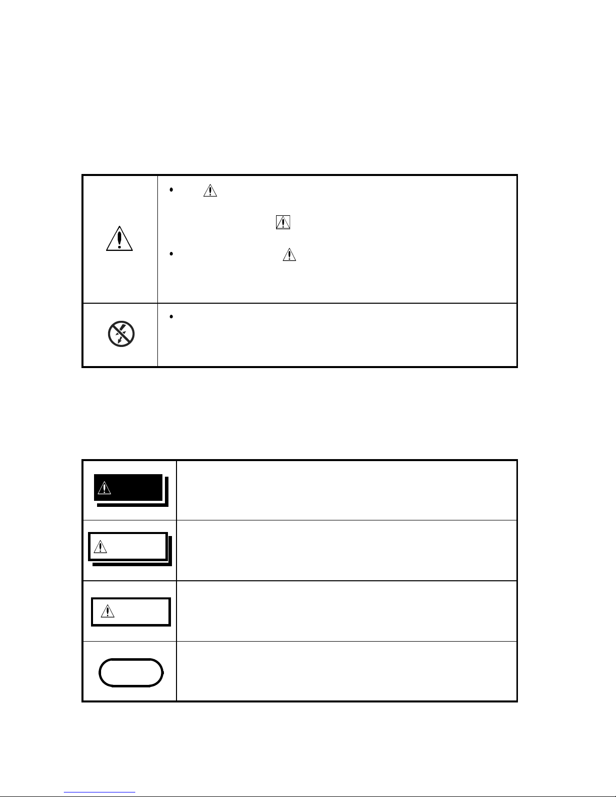
CAUTION
Indicates that incorrect operation presents a possibility of
injury to the user or damage to the device.
NOTE
Indicates advisory items related to performance or correct
operation of the device.
Safety Symbols
This manual contains information and warnings essential for safe
operation of the device and for maintaining it in safe operating
condition. Before using the device, be sure to carefully read the
following safety notes.
The following symbols in this manual indicate the relative
importance of cautions and warnings.
Page 7
3
――――――――――――――――――――――――――――――――――――――
――――――――――――――――――――――――――――――――――
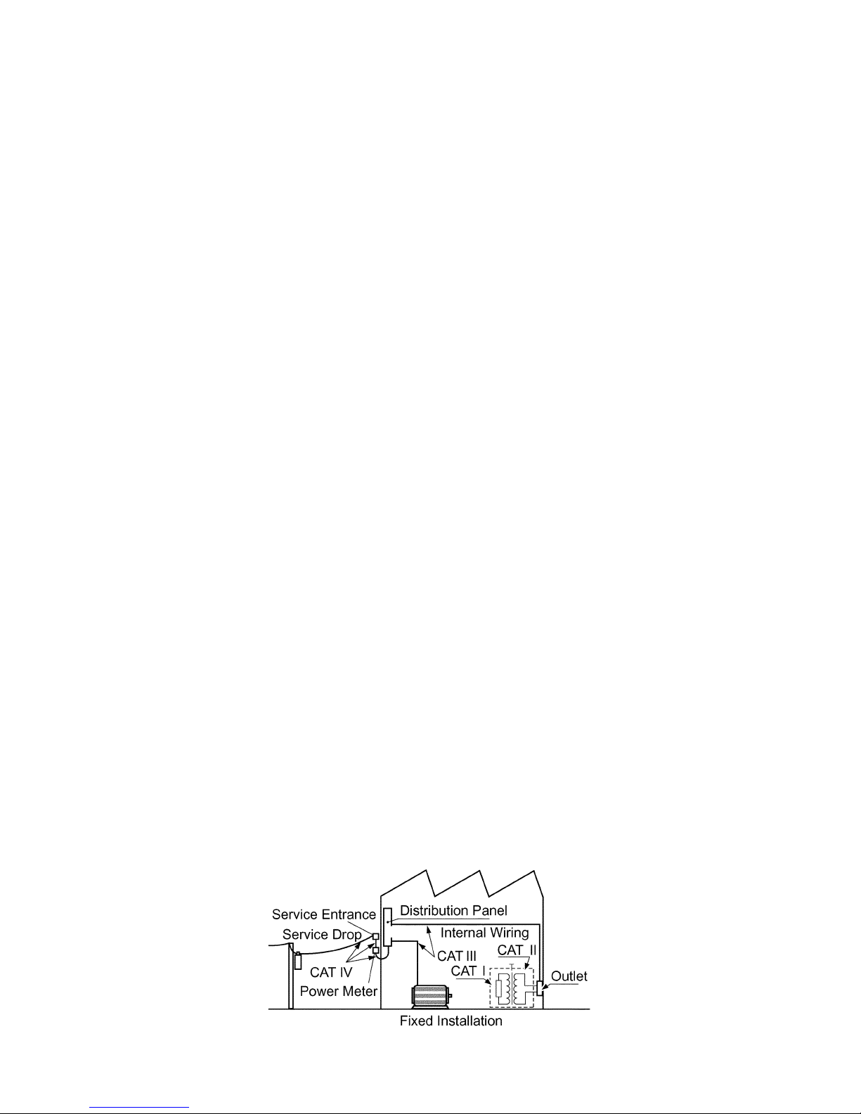
Measurement categories (Overvoltage categories)
This device conforms to the safety requirements for CAT II
(600V), CAT III (300V) measurement instruments.
To ensure safe operation of measurement devices, IEC 61010
establishes safety standards for various electrical environments,
categorized as CAT I to CAT IV, and called measurement
categories. These are defined as follows.
CAT I : Secondary electrical circuits that are connected to a wall
outlet through a transformer or similar instrument.
CAT II : Primary electrical circuits in equipment connected to a
wall outlet via a power cord (portable tools, household
appliances, etc.)
CAT III : Primary electrical circuits of heavy equip ment (fixed
installations) connected directly to the distribution
panel, and feeders between the distribution panel and
outlets.
CAT IV : The circuit from the service drop to the service entrance,
then to the power meter and to the primary overcurrent
protection instrument.
Higher-numbered categories correspond to electrical environments
with greater momentary energy. So a measurement device
designed for CAT III environments can endure greater momentary
energythanadevicedesignedforCATII.
Using a measurement device in an environment designated with a
higher-numbered category than that for which the device is rated
could result in a severe accident, and must be carefully avoided.
Never use a CAT I measuring device in CAT II, III, or IV
environments.
The measurement categories comply with the Overvoltage
Categories of the IEC60664 Standards.
Page 8
4
――――――――――――――――――――――――――――――――――――――
――――――――――――――――――――――――――――――――――
DANGER
To avoid short circuits and potentially life-threatening
hazards, follow these precautions.
z Never attach the clamp to a circuit that operates at
more than the maximum rated voltage to earth.
z For safety's sake, avoid clamping around bare
conductors, while clamping or measuring.
z While clamping and measuring, do not touch the
clamp in front of the barrier or the conductor being
measured.
z Be careful to avoid damaging the insulation surface
while taking measurements.
z This device is made for use with the 3269 or 3272
POWER SUPPLY. It is possible to use a power
supply other than the 3269 or 3272, provided that
the connector and pin assignments match, and that
voltage and other electrical specifications are
satisfied. In the interest of safety, make sure that
the power supply has a protective earthing with
double-insulation construction.
z Make sure that the waveform measuring equipment
connected to this device's output terminal (BNC) is
equipped with a protective earthing with doubleinsulation construction.
Notes on Use
Follow these precautions to ensure safe operation and to obtain
the full benefits of the various functions.
Page 9
5
――――――――――――――――――――――――――――――――――――――
――――――――――――――――――――――――――――――――――
DANGER
z If the waveform measuring instrument being
connected to the output terminal (BNC) on this
device is equipped with any other measurement
terminals, take the following precautions to ensure
that the other instrument does not form a bridge
between the probe and any hazardous live of a
part.
1. Isolate the terminal to which the probe is
connected from other terminals on the measuring
instrument using basic insulation
conforming to
the measurement category
, working voltage, and
pollution degree
requirements of the circuit being
tested.
2. If basic insulation
requirements cannot be met
between the terminal to which this device is
connected and other terminals of the measuring
instrument, make sure that the voltage input to
the measurement terminal does not exceed the
Separated Extra-Low Voltage Earthed (SELV-E)
.
3. Read and observe all warnings and precautions
relating to electrical safety for the measuring
instrument being connected to the probe.
Refer to the following standards regarding the
meanings of underlined terms.
IEC 61010-1
IEC 61010-031
IEC 61010-2-032
Page 10
6
――――――――――――――――――――――――――――――――――――――
――――――――――――――――――――――――――――――――――
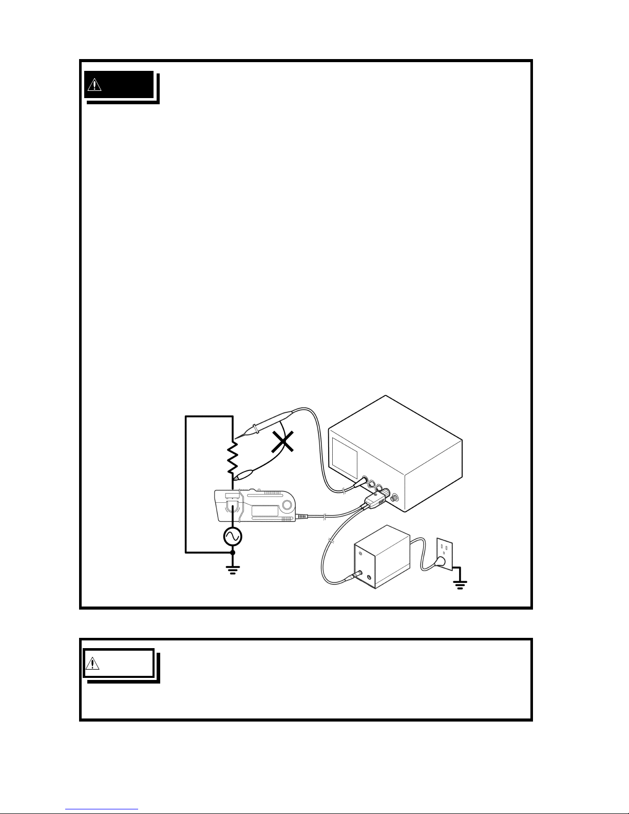
DANGER
z Be sure to observe all operating precautions for the
waveform monitoring instrument (oscilloscope or
recorder) and other measurement instruments to
which this device is connected
z When using a measurement instrument that does
not provide isolation between its input terminals
and chassis or other input terminals, please pay
attention to the following points.
If a signal is applied to an input terminal other than
that to which this device is connected, do not
connect the ground-side terminal to any nonground potential. Otherwise, short-circuit current
will flow through the 3269 or 3272, or this device
from the ground terminal, which could cause an
electrical accident or damage.
WARNING
z Do not allow the device to get wet, and do not take
measurements with wet hands. This may cause an
electric shock.
Page 11
7
――――――――――――――――――――――――――――――――――――――
――――――――――――――――――――――――――――――――――
CAUTION
z To avoid damage to the device, protect it from vibration
or shock during transport and handling, and be
especially careful to avoid dropping.
z Do not store or use the device where it could be
exposed to direct sunlight, high temperature, humidity,
or condensation. Under such conditions, the device
may be damaged and insulation may deteriorate so
that it no longer meets specifications.
z Before using the device the first time, verify that it
operates normally to ensure that the no damage
occurred during storage or shipping. If you find any
damage, contact your dealer or Hioki representative.
z This device is not designed to be entirely water- or
dust- proof. To avoid damage, do not use it in a wet or
dusty environment.
z The sensor head is a precision assembly including a
molded component, a ferrite core, and a Hall effect
element. It may be damaged if subjected to sudden
changes in ambient temperature, or mechanical strain
or shock, and therefore great care should be exercised
in handling it.
z The matching surfaces of the sensor head are
precision ground, and should be treated with care. If
these surfaces are scratched, performance may be
impaired.
z Foreign substances such as dust on the contact
surfaces of the sensor head can cause acoustic
resonance and degrade measurement, so it should be
cleaned by gently wiping with a soft cloth.
z To avoid damaging the sensor cable and power supply
cable, do not bend or pull the cables.
Page 12

8
――――――――――――――――――――――――――――――――――――――
――――――――――――――――――――――――――――――――――
CAUTION
z When the power is on, keep closed, except when
clamping them onto the conductor to be measured.
The facing surface of the core section can be
scratched while it is open.
NOTE
z Correct measurement may be impossible in the presence of strong
magnetic fields, such as near transformers and high-current
conductors, or in the presence of strong electromagnetic fields
such as near radio transmitters.
Service / Maintenance
z To clean the device, wipe it gently with a soft cloth moistened
with water or mild detergent. Never use solvents such as
benzene, alcohol, acetone, ether, ketones, thinners or gasoline, as
they can deform and discolor the case.
z If the device seems to be malfunctioning, contact your dealer or
Hioki representative.
z When sending the device for repair, pack carefully to prevent
damage in transit. Include cushioning material so the device
cannot move within the package. Be sure to include details of
the problem.
z Hioki cannot be responsible for damage that occurs during
shipment.
Page 13

9
――――――――――――――――――――――――――――――――――――――
Chapter 1 Overview
――――――――――――――――――――――――――――――――――
Chapter 1
Overview
1.1 Product Overview
1.2 Features
This device can be directly connected to a BNC input connector
of a waveform measuring instrument such as an oscilloscope or
recorder, and by clamping on a conductor to be measured, allows
the current waveform to be easily captured.
z Highly accurate current detection.
z Easy current measurement.
z Broadband frequency characteristics DC to 10 MHz.
z Large diameter allows high-current measurements.
z Easy protection function to avoid self-heating during excessive
input.
z Unique HIOKI development of thin film Hall effect element
Page 14

10
――――――――――――――――――――――――――――――――――――――
Chapter 1 Overview
――――――――――――――――――――――――――――――――――
Current direction indication
Terminator
Sensor cable
Power supply cable
"UNLOCK" indication
(inside)
Sensor
"LOCK" indication
3
4
1
5
2
2
7
8
6
9
1.3 Names of Parts
External view
Page 15

11
――――――――――――――――――――――――――――――――――――――
Chapter 1 Overview
――――――――――――――――――――――――――――――――――
1.4 Parts of the Sensor
1. Clamp
This clamps around the conductor to be measured.
2. Slider
This slider opens the clamp. Always use it to open and close the
clamp.
3. Lever
This lock mechanism keeps the clamp closed.
4. Sensor head
This clamps the conductor being measured, and carries out the
actual current measurement. It is a precision assembly including a
molded component, a ferrite core, and a Hall effect element. It
may be damaged if subjected to sudden changes in ambient
temperature, or mechanical strain or shock, and therefore great
care should be exercised in handling it.
5. Barrier
This structure reduces the likelihood of touching the conductor
while testing, and indicates the limit of safe physical contact.
Avoid touching the clamp in front of the barrier when clamping
or measuring.
6. Demagnetizing switch (DEMAG)
This demagnetizes the core if it has been magnetized by switching
the power on and off, or by an excessive input. Always carry out
demagnetizing before measurement.
The demagnetizing process takes about 3 second. During
demagnetizing, a demagnetizing waveform is output.
7. Zero adjustment dial (ZERO ADJ)
Use the zero adjustment dial to correct for the effect of a voltage
offset or temperature drift on the device.
When beginning measurement, after demagnetizing always carry
out zero adjustment.
Page 16

12
――――――――――――――――――――――――――――――――――――――
Chapter 1 Overview
――――――――――――――――――――――――――――――――――
NOTE
8. Output connector
The current waveform of the measured conductor is output at a
constant rate (0.01 V/A).
Connect to the BNC input connector of the waveform measuring
instrument.
z The output of this device is terminated internally. Use a high-
impedance input to the measuring instrument. With an input
impedance of 50 Ω, accurate measurement is not possible.
z If using BNC-banana plug adapters or similar to connect to input
terminals other than BNC connectors, make sure the polarity is
correct.
z Turn the collar until it clicks, and check that it is locked
securely.
9. Power plug
Connect this to the 3269 or 3272 POWER SUPPLY receptacle to
supply power to the sensor terminator.
Page 17

13
――――――――――――――――――――――――――――――――――――――
Chapter 2 Specifications
――――――――――――――――――――――――――――――――――
Bandwidth DC to 10 MHz (-3 dB)
(Typical characteristics shown in Fig.1)
Rise time 35 ns or less
Maximum
continuous input
range
150 A
Derating according to frequency shown in Fig.2
Maximum peak
current value
Non-continuous 300 A peak;
at pulse width
30 μs, 500 A peak
Output voltage rate 0.01 V/A
Amplitude
accuracy
To 150 A: 1.0% rdg. 1mV
150 A to 300 Apeak:
2.0% rdg.
(DC,and45to66Hz)
Noise Equivalent to 25 mA rms or less (for 20 MHz band
measuring instrument)
Input impedance (Typical characteristics shown in Fig.3)
Temperature
coefficient for
sensitivity
2% or less (Input: 55 Hz 150 A, within a range of 0
to 40
, within a range of 32 to 104 )
Maximum rated
power
5.5 VA max. (within maximum continuous input range)
Rated supply
voltage
12 V 1V
Chapter 2
Specifications
2.1 Product Specifications
Guaranteed at 23
±
5
(73
±
9
) after the power has been
on for 30 minutes.
Page 18

14
――――――――――――――――――――――――――――――――――――――
Chapter 2 Specifications
――――――――――――――――――――――――――――――――――
Operating
temperature and
humidity range
0to40 (32 to 104 ), 80 %RH or less (no
condensation)
Storage
temperature and
humidity range
-
10 to 50 (14 to 122 ), 80 %RH or less (no
condensation)
Location for use Indoor, altitude up to 2000 m (6562 feet)
Period of
guaranteed
accuracy
1 year (Opening/Closing up to 10,000 times)
Effect of external
magnetic fields
Equivalent to a maximum of 150 mA (in a DC or 60
Hz, 400 A/m magnetic field)
Maximum rated
voltage to earth
600 V CAT II, 300 V CAT III (insulated conductor)
Diameter of
measurable
conductors
20 mm dia.
0.79" dia.
Cable lengths Sensor cable Approx. 2 m (78.7")
Power supply cable Approx. 1 m (39.4")
External
dimensions
Sensor Approx. 176W X 69H X 27D mm
Approx. 6.93"W X 2.72"H X 1.06"D
Terminator Approx. 27H X 55W X 18D mm
Approx.1.06"W X 2.17"H X 0.71"D
Mass Approx. 500 g
Approx. 17.6 oz.
Accessories Instruction manual, Carrying case
Safety EN61010-2-032:2002
Measurement category II, III (anticipated transient
overvoltage 4000 V), Pollution Degree 2
EMC EN61326:1997+A1:1998+A2:2001+A3:2003
2.2 Standards Applying
Page 19

15
――――――――――――――――――――――――――――――――――――――
Chapter 2 Specifications
――――――――――――――――――――――――――――――――――
Fig.1 Frequency characteristics (Typical characteristics)
Frequency [Hz]
A
m
p
l
i
t
u
d
e
[
d
b
,
0
d
B
=
1
V
]
Frequency [Hz]
M
a
x
i
m
u
m
i
n
p
u
t
c
u
r
r
e
n
t
[
A
r
m
s
]
Fig.2 Derating according to frequency
I
n
p
u
t
i
m
p
e
d
a
n
c
e
[
o
h
m
]
Fig.3 Input impedance (Typical characteristics)
Frequency [Hz]
Page 20

16
――――――――――――――――――――――――――――――――――――――
Chapter 2 Specifications
――――――――――――――――――――――――――――――――――
Page 21

17
――――――――――――――――――――――――――――――――――――――
Chapter 3 Measurement Procedure
――――――――――――――――――――――――――――――――――
DANGER
To avoid short circuits and potentially life-threatening
hazards, follow these precautions.
z Never attach the clamp to a circuit that operates at
more than the maximum rated voltage to earth.
z For safety's sake, avoid clamping around bare
conductors, while clamping or measuring.
z While clamping and measuring, do not touch the
clamp in front of the barrier or the conductor being
measured.
z Be careful to avoid damaging the insulation surface
while taking measurements.
z This device is made for use with the 3269 or 3272
POWER SUPPLY. It is possible to use a power
supply other than the 3269 or 3272, provided that
the connector and pin assignments match, and that
voltage and other electrical specifications are
satisfied. In the interest of safety, make sure that
the power supply has a protective earthing with
double-insulation construction.
z Make sure that the waveform measuring equipment
connected to this device's output terminal (BNC) is
equipped with a protective earthing with doubleinsulation construction.
Chapter 3
Measurement Procedure
3.1 Notes on Use
Page 22

18
――――――――――――――――――――――――――――――――――――――
Chapter 3 Measurement Procedure
――――――――――――――――――――――――――――――――――
DANGER
z Make sure that the waveform measuring equipment
connected to this device's output terminal (BNC) is
equipped with a protective earthing with doubleinsulation construction.
z If the waveform measuring instrument being
connected to the output terminal (BNC) on this
device is equipped with any other measurement
terminals, take the following precautions to ensure
that the other instrument does not form a bridge
between the probe and any hazardous live of a
part.
1. Isolate the terminal to which the probe is
connected from other terminals on the measuring
instrument using basic insulation
conforming to
the measurement category
, working voltage, and
pollution degree
requirements of the circuit being
tested.
2. If basic insulation
requirements cannot be met
between the terminal to which this device is
connected and other terminals of the measuring
instrument, make sure that the voltage input to
the measurement terminal does not exceed the
Separated Extra-Low Voltage Earthed (SELV-E)
.
3. Read and observe all warnings and precautions
relating to electrical safety for the measuring
instrument being connected to the probe.
Refer to the following standards regarding the
meanings of underlined terms.
IEC 61010-1
IEC 61010-031
IEC 61010-2-032
Page 23

19
――――――――――――――――――――――――――――――――――――――
Chapter 3 Measurement Procedure
――――――――――――――――――――――――――――――――――
DANGER
z Be sure to observe all operating precautions for the
waveform monitoring instrument (oscilloscope or
recorder) and other measurement instruments to
which this device is connected
z When using a measurement instrument that does
not provide isolation between its input terminals
and chassis or other input terminals, please pay
attention to the following points.
If a signal is applied to an input terminal other than
that to which this device is connected, do not
connect the ground-side terminal to any nonground potential. Otherwise, short-circuit current
will flow through the 3269 or 3272, or this device
from the ground terminal, which could cause an
electrical accident or damage.
Page 24

20
――――――――――――――――――――――――――――――――――――――
Chapter 3 Measurement Procedure
――――――――――――――――――――――――――――――――――
CAUTION
Before turning on the power, make sure that the voltage
of the power supply being used matches the supply
voltage indicated on the rear panel of the 3269 or 3272.
NOTE
3.2 Preparations for Measurement
(1) Have the 3269 or 3272 POWER SUPPLY, and oscilloscope or
recorder for waveform measurement ready.
z The output of this device is terminated internally. Use a high-
impedance input to the measuring instrument. With an input
impedance of 50 Ω, accurate measurement is not possible.
z Depending on the current value being measured, there are cases
in which two CLAMP ON PROBEs cannot be used
simultaneously on the 3272. Power consumption on the CLAMP
ON PROBE depends on the current value being measured.
(2) Turn the power switch off and connect the power cord.
(3) Connect the power plug of the 3274 to the power receptacle of the
3269 or 3272.
(4) Turn the 3269 or 3272 power switch on, and check that the front
panel power indicator lights.
Page 25

21
――――――――――――――――――――――――――――――――――――――
Chapter 3 Measurement Procedure
――――――――――――――――――――――――――――――――――
CAUTION
z When disconnecting the output connector, be sure to
release the lock before pulling off the connector. Forcibly
pulling the connector without releasing the lock, or pulling
on the cable, can damage the terminator.
z If using BNC-banana plug adapters or similar to connect
to input terminals other than BNC connectors, make sure
the polarity is correct.
z Do not demagnetize while the 3274 is clamping a
conductor to be measured. Demagnetizing causes current
to flow into the conductor, which may damage parts in the
circuit to be measured.
Demagnetizing
Conductor
z Check that the conductor being measured is not clamped
when supplying power to the 3274 for the same reason.
Demagnetized waveforms are generated when supplying
electric power.
3.3 Demagnetizing and Zero Adjustment
(1) With the waveform measurement instrument input at ground,
adjust the trace to the zero position.
(2) Set the input coupling of the waveform measurement instrument
to DC.
(3) Connect the output connector of the 3274 to the input connector
of the waveform measurement instrument. Turn the collar until it
clicks, and check that it is locked securely.
Page 26

22
――――――――――――――――――――――――――――――――――――――
Chapter 3 Measurement Procedure
――――――――――――――――――――――――――――――――――
I
3.4 Measurement Procedure
(4) Before clamping a conductor, confirm that the clamp can be
securely closed: press the slider until UNLOCK is no longer
displayed, and hold it until LOCK appears.
(5) Press the demagnetizing switch (DEMAG) on the terminator.
(6) Turn the zero adjustment dial on the terminator, to adjust the trace
to the zero position.
(1) Check that the system is safe, and that the preparations described
in the preceding section have been carried out.
(2) Pull the sensor slider, so that the clamp opens.
(3) Align the sensor so that the current direction indication
corresponds to the direction of current flow through the conductor
to be measured, and clamp so that the conductor is in the center
of the sensor aperture.
(4) Press the slider on the sensor head until the "UNLOCK"
indication disappears, and hold it until LOCK appears, and check
that the opening lever is firmly locked and the clamp securely
closed.
(5) It is now possible to monitor the current waveform. The output
rate of the 3274 is 0.01 V/A. The current sensitivity can be
derived from the voltage sensitivity of the waveform measurement
instrument. For example, if the voltage sensitivity is 10
mV/division, the current sensitivity is 1 A/division.
Page 27

23
――――――――――――――――――――――――――――――――――――――
Chapter 3 Measurement Procedure
――――――――――――――――――――――――――――――――――
NOTE
0
100
200
300
400
500
600
0 100 200 300
AC(f=50Hz)
DC
C
o
n
s
u
m
p
t
i
o
n
c
u
r
r
e
n
t
(
m
A
)
Current (A)
CAUTION
z The maximum continuous input range is based on
heat that is internally generated during
measurement. Never input current in excess of this
level. Exceeding the rated level may result in
damage to the probe.
z The maximum continuous input range varies
according to the frequency of the current being
measured. See the figures in Chapter 2,
"Specifications"
z If excess current is input, generated heat activates
a built-in safety function that blocks normal output.
If this happens, remove the input immediately
(remove the sensor from the conductor being
measured, or reduce the input current to zero).
Wait until the sensor has had sufficient time to cool
before resuming operation.
・
When using the 3274, note that two clamp-on probes may not be
used simultaneously with the 3272 POWER SUPPLY, depending
on the current to be measured.
・
The current consumption of clamp-on probes depends on the
current to be measured. Confirm that the total current
consumption of the clamp-on probes does not exceed the rated
output current of the 3272. See Figure 1.
Fig.1
Current consumption* vs. current to be measured (typical)
*The sum total of a positive and negative current consumption
Page 28

24
――――――――――――――――――――――――――――――――――――――
Chapter 3 Measurement Procedure
――――――――――――――――――――――――――――――――――
CAUTION
z Even if the input current does not exceed the rated
continuous maximum, continuous input for an
extended period of time may result in activation of
the safety circuit to prevent damage resulting from
heating of the sensor.
z At high ambient temperatures, the built-in safety
circuit may activate at current input levels below
the rated continuous maximum.
z Continuous input of current exceeding the rated
maximum or repeated activation of the safety
function may result in damage to the device.
z The probe is rated for maximum input under two
conditions in addition to the input maximums
shown in the Product Specifications. These are (1)
300 Apeak, for non-continuous input, and (2) 500
Apeak for pulse widths
30 μs. (1) indicates an
upper waveform response limit of 300 Apeak. Use
the sensor at RMS current input levels that are
within the rated continuous maximums. (2)
indicates the upper response limit for a single input
pulse. Do not allow current level to exceed the
specified limit of the operating range.
z To avoid damage to the device, when opening the
clamp of the probe, be sure to operate with the
slider.
Page 29

25
――――――――――――――――――――――――――――――――――――――
Chapter 3 Measurement Procedure
――――――――――――――――――――――――――――――――――
NOTE
z The output of this device is terminated internally. Use a
waveform measurement instrument with an input impedance of at
least 1 MΩ.
z Immediately after powering on, this device may be subject to an
appreciable offset drift due to the effect of self-heating. To
counteract this, allow the device to warm up for about 30
minutes before carrying out measurement.
z When performing continuous measurements, it is necessary to be
aware that the offset voltage drifts, depending on factors such as
the ambient temperature.
z Under certain circumstances, oscillation may occur if the probe is
connected to the 3269 or 3272 POWER SUPPLY while the
power supply is on. This does not indicate a malfunction.
Oscillation can be stopped and operation restored to normal by
opening and closing the clamp.
z Acoustic resonance may occur depending on the level and
frequency of the measured current. This does not normally affect
measurements unless a foreign substance such as dust is present
on the contact surfaces of the sensor head.
z The reading may be affected by the position within the clamp
aperture of the conductor being measured. The conductor should
be in the center of the clamp aperture.
z When carrying out measurement, press the slider on the sensor
head until the "UNLOCK" indication disappears, and hold it until
LOCK appears, and check that the opening lever is firmly locked
and the clamp securely closed. Correct measurements cannot be
performed unless the clamp is securely closed and the slider is
pressed until LOCK is displayed.
Page 30

26
――――――――――――――――――――――――――――――――――――――
Chapter 3 Measurement Procedure
――――――――――――――――――――――――――――――――――
Power source Load
High
Low
z At high frequencies, common mode noise may affect
measurements taken on the high voltage side of circuits. If this
occurs, reduce the frequency range of the waveform measuring
instrument, or clamp onto the low-voltage side of the circuit, as
appropriate.
z When power is turned on, a demagnetizing waveform is initially
applied to the output: this is intentional in the design, and not a
fault.
z Accurate measurement may be impossible in locations subject to
strong external magnetic fields, such as transformers and high-
current conductors, or in locations subject to strong external
electric fields, such as radio transmission equipment.
Page 31

Page 32

Page 33

Page 34

Page 35

HIOKI 3274 CLAMP ON PROBE
Instruction Manual
Publication date: September 2006 Revised edition 4
Edited and published by HIOKI E.E. CORPORATION
Technical Support Section
All inquiries to International Sales and Marketing Department
81 Koizumi, Ueda, Nagano, 386-1192, Japan
TEL: +81-268-28-0562 / FAX: +81-268-28-0568
E-mail: os-com@hioki.co.jp
URL http://www.hioki.co.jp/
Printed in Japan 3274A981-04
All reasonable care has been taken in the production of this manual,
but if you find any points which are unclear or in error, please
contact your supplier or the International Sales and Marketing
Department at HIOKI headquarters.
In the interests of product development, the contents of this manual
are subject to revision without prior notice.
Unauthorized reproduction or copying of this manual is prohibited.
Page 36

HEAD OFFICE
81 Koizumi, Ueda, Nagano 386-1192, Japan
TEL +81-268-28-0562 / FAX +81-268-28-0568
E-mail: os-com@hioki.co.jp / URL http://www.hioki.co.jp/
HIOKI USA CORPORATION
6 Corporate Drive, Cranbury, NJ 08512, USA
TEL +1-609-409-9109 / FAX +1-609-409-9108
3274A981-04 06-09H
Printed on recycled paper
2003-01
改訂 枠消す
 Loading...