

Page 1
3273-50
3276A981-05
3276
CLAMP ON PROBE
Instruction Manual
Mar. 2020 Revised edition 5
3276A981-05 20-03H
EN
Page 2

3276A981-05
Page 3
Contents
3276A981-05
Introduction i
Inspection
Notes on Safety
Notes on Use
Chapter 1 Overview
1.1 Product Overview 1
1.2 Features
1.3 Names of Parts
1.4 Parts of the Sensor
Chapter 2 Specifications 5
2.1 Product Specifications 5
2.2 Standards Applying
Chapter 3 Measurement Procedure 11
3.1 Notes on Use 11
3.2 Preparations for Measurement
3.3 Demagnetizing and Zero Adjustment
3.4 Measurement Procedure
11
12
16
i
i
iii
1
1
2
2
7
3276A981-05
Page 4

3276A981-05
Page 5
―――――――――――――――――――――――――――
3276A981-05
Introduction
Thank you for purchasing the HIOKI 3273-50,3276
CLAMP ON PROBE. To obtain maximum
performance from the device, please read this
manual first, and keep it handy for future reference.
Inspection
When you receive the device, inspect it carefully to
ensure that no damage occurred during shipping. If
damage is evident, or if it fails to operate according
to the specifications, contact your dealer or Hioki
representative.
Supplied accessories
Instruction manual 1
3273-50 Soft case 1
3276 Carrying case 1
Notes on Safety
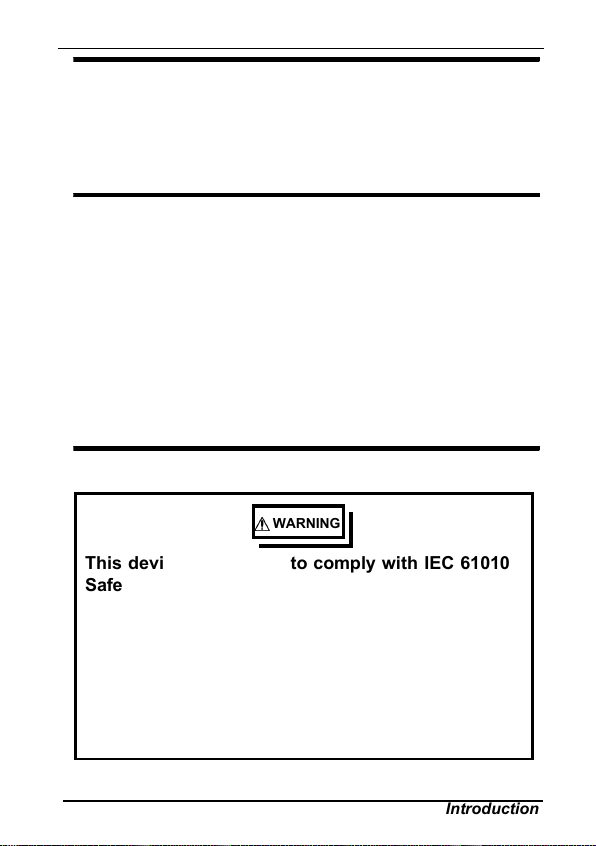
WARNING
This deviceis designed to comply with IEC 61010
Safety Standards, and has been thoroughly tested
for safety prior to shipment. However,
mishandling during use could result in injury or
death, as well as damage to the device. Be certain
that you understand the instructions and
precautions in the manual before use. W e
disclaim any responsibility for accidents or
injuries not resulting directly from device defects.
i
――――――――――――――――――――――――
Introduction
Page 6
ii
3276A981-05
―――――――――――――――――――――――――――
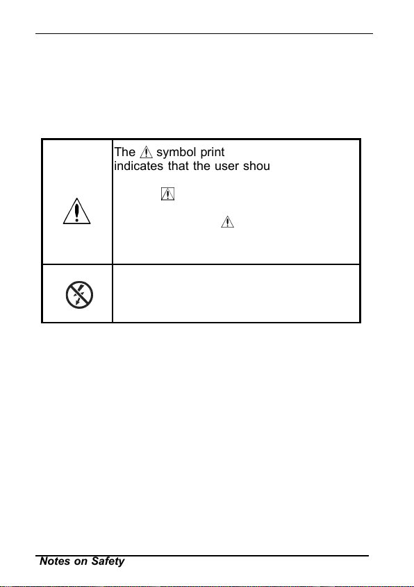
Safety Symbols
This manual contains information and warnings
essential for safe operation of the device and for
maintaining it in safe operating condition. Before
using the device, be sure to carefully read the
following safety notes.
The symbol printed on the device
indicates that the user should refer to a
corresponding topic in the manual (marked
with the
symbol) before using the
relevant function.
In the manual, the
symbol indicates
particularly important information that the
user should read before using the device.
Indicates that only insulated conductors
suited to the voltage of the circuit under
test can be measured.
――――――――――――――――――――――――
Notes on Safety
Page 7
―――――――――――――――――――――――――――
3276A981-05
iii
The following symbols in this manual indicate the
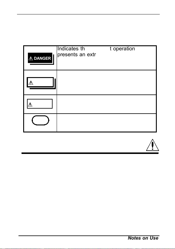
relative importance of cautions and warnings.
Indicates that incorrect operation
DANGER
presents an extreme hazard that could
result in serious injury or death to the
user.
Indicates that incorrect operation
WARN ING
presents a significant hazard that could
result in serious injury or death to the
user.
Indicates that incorrect operation
CAUTION
presents a possibility of injury to the user
or damage to the device.
NOTE
Indicates advisory items related to
performance or correct operation of the
device.
Notes on Use
Follow these precautions to ensure safe operation
and to obtain the full benefits of the various
functions.
――――――――――――――――――――――――
Preliminary Check
Before using the device the first time, verify that it
operates normally to ensure that the no damage
occurred during storage or shipping. If you find any
damage, contact your dealer or Hioki representative.
Notes on Use
Page 8
iv
3276A981-05
―――――――――――――――――――――――――――
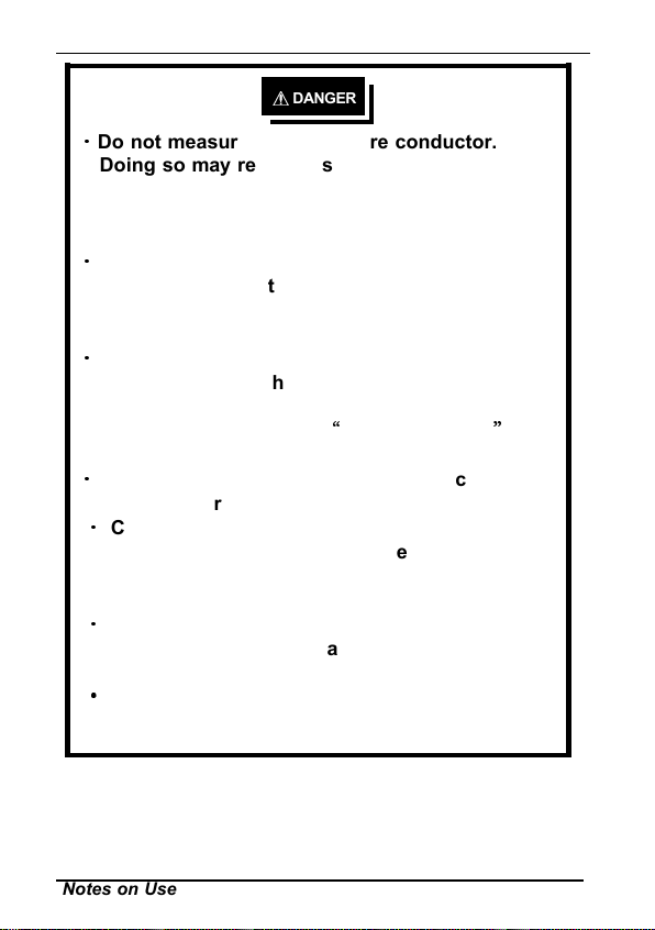
DANGER
・
Do not measure around a bare conductor.
Doing so may result in short-circuit or electric
shock. Take measurements at a location on an
insulated wire where there is sufficient
insulation for the circuit voltage.
・
Refer to the derating characteristics when
measuring current that includes a
highfrequency component and never measure
any current that exceeds the rated current.
・
Use with high frequencies or strong magnetic
fields may cause the device to become
abnormally hot, resulting in fire, equipment
damage, or burns. (See“3 Specifications
”
(p5.))
・
Observe the following to avoid electric shock
and short circuits.
・
Connect the device to the 3269 or the 3272
Power Supply and waveform measurement
instrument (oscilloscope or recorder) first, and
then to the active lines to be measured
・
When the sensor is opened, do not shortcircuit
the conductor being measured or other two
wires with the metal part of the tip.
Be careful to avoid damaging the insulation
surface while taking measurements.
――――――――――――――――――――――――
Notes on Use
Page 9
―――――――――――――――――――――――――――
3276A981-05
DANGER
・
Before clamping the conductor being
measured,make sure that the insulation on the
conductor isundamaged. Also, take care not to
damage theinsulation when clamping the
conductor. Any damageto the insulation could
cause an electric shock.
This instrument is made for use with the 3269
or 3272 POWER SUPPLY.
To prevent fire or damage of the measurement
target and device as well as burns, exercise
caution concerning the following when
measuring high-frequency currents or currents
that contain high-frequency components:
Eddy current loss may cause heating of the
sensor head.
Dielectric heating may cause heating of cord
insulation and other materials.
This device should only be connected to the
secondary side of a breaker, so the breaker
can prevent an accident if a short circuit
occurs. Connections should never be made to
the primary side of a breaker, because
unrestricted current flow could cause a
serious accident if a short circuit occurs.
v
――――――――――――――――――――――――
Notes on Use
Page 10

vi
3276A981-05
―――――――――――――――――――――――――――
DANGER
Be sure to observe all operating precautions for
the waveform monitoring instrument
(oscilloscope or recorder) and other
measurement instruments to which this device
is connected.
When using a measurement instrument that
does not provide isolation between its input
terminals and chassis or other input terminals,
please pay attention to the following points.
If a signal is applied to an input terminal other
than that to which this device is connected, do
not connect the ground-side terminal to any
non-ground potential. Otherwise, short-circuit
current will flow through the 3269,3272 or this
device from the ground terminal, which could
cause an electrical accident or damage.
――――――――――――――――――――――――
Notes on Use
Page 11

―――――――――――――――――――――――――――
3276A981-05
vii
WARNING
Do not allow the device to get wet, and do not take
measurements with wet hands. This may cause an
electric shock.
・
Do not press the demagnetizing switch (DEMAG)
to perform demagnetization while the conductor
being measured is clamped. Doing so could
damage the circuitry or cause an accident that
might result in injury or death.
・
Ensure that the input does not exceed the
maximum rated current to avoid device damage,
shortcircuiting and electric shock resulting from
heat building.
――――――――――――――――――――――――
Notes on Use
Page 12
viii
3276A981-05
―――――――――――――――――――――――――――
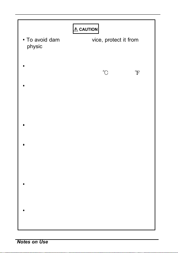
CAUTION
To avoid damage to the device, protect it from
physical shock when transporting and handling. Be
especially careful to avoid physical shock from
dropping.
This device should be installed and operated
indoors only, between 0 and 40
(32 to 104 )
and 80% RH or less.
Do not store or use the device where it could be
exposed to direct sunlight, high temperature or
humidity, or condensation. Under such conditions,
the device may be damaged and insulation may
deteriorate so that it no longer meets
specifications.
This device is not designed to be entirely water- or
dust-proof. To avoid damage, do not use it in a wet
or dusty environment.
The sensor head is a precision assembly including
a molded component, a ferrite core, and a Hall
effect element. It may be damaged if subjected to
sudden changes in ambient temperature, or
mechanical strain or shock, and therefore great
care should be exercised in handling it.
The matching surfaces of the sensor head are
precisely ground, and should be treated with care.
If these surfaces are scratched, performance may
be impaired.
Measurements are degraded by dirt on the mating
surfaces of the sensor head, so keep the surfaces
clean by gently wiping with a soft cloth.
――――――――――――――――――――――――
Notes on Use
Page 13
―――――――――――――――――――――――――――
3276A981-05
ix
CAUTION
Foreign substances such as dust on the contact
surfaces of the sensor head can cause acoustic
resonance and degrade measurement, so it should
be cleaned by gently wiping with a soft cloth.
Refer to NOTE (p. 23) for resonance sound.
To avoid damaging the cables, do not bend or pull
the sensor cable and power supply cable.
Keep the clamp jaws and core slits free from
foreign objects, which could interfere with clamping
action.
・
Do not apply a static electricity or other source of
high voltage to the sensor. Doing so may damage
its internal Hall elements and circuitry
・
To clean the device, wipe it gently with a soft cloth
moistened with water or mild detergent. Never
use solvents such as benzene, alcohol, acetone,
ether, ketones, thinners or gasoline, as they can
deform and discolor the case.
When the power is on, keep the core section of the
sensor closed, except when clamping them onto
the conductor to be measured. The facing surface
of the core section can be scratched while it is
open
.Do not short-circuit the output terminal and do not
input voltage to the output terminal. The device
may be damaged.
――――――――――――――――――――――――
Notes on Use
Page 14

x
3276A981-05
―――――――――――――――――――――――――――
CAUTION
Keep the cables well away from heat sources, as
bare conductors could be exposed if the insulation
melts.
Keep the sensor head closed when not in use, to
avoid accumulating dust or dirt on the mating core
surfaces, which could interfere with clamp
performance.
NOTE
Correct measurement may be impossible in the
presence of strong magnetic fields, such as
near transformers and high-current conductors,
or in the presence of strong electromagnetic
fields such as near radio transmitters.
Service
When sending the device for repair, carefully to
prevent damage in transit. Include cushioning
material so the instrument cannot move within
the package. Be sure to include details of the
problem. Hioki cannot be responsible for
damage that occurs during shipment.
IMPORTANT
Periodic calibration is necessary in order to
ensure that the device provides correct
measurement results of the specified accuracy.
――――――――――――――――――――――――
Notes on Use
Page 15

―――――――――――――――――――――――――――
3276A981-05
Chapter 1
Overview
1.1 Product Overview
This device can be directly connected to a BNC
input connector of a waveform measuring
instrument such as an oscilloscope or recorder, and
by clamping on a conductor to be measured, allows
the current waveform to be easily captured.
1.2 Features
Highly accurate current detection
Easy current measurement
Broadband frequency characteristics
3273-50: DC~50MHz
3276: DC~100MHz
Compact and permits measurement of low
current levels
Easy protect function at excessive input
Unique HIOKI development of thin film Hall
effect element
1
――――――――――――――――――――――――
Chapter 1 Overview
Page 16

2
3276A981-05
―――――――――――――――――――――――――――
1.3 Names of Parts
External view
Current direction
indication
Sensor Terminator
3
1
"UNLOCK" indication
2
Sensor cable
5
Power supply
cable
1.4 Parts of the Sensor
Opening lever
1
Operating lever for opening the sensor head. Always
use this lever to open the sensor head.
Sensor head
2
This clamps the conductor being measured, and
carries out the actual current measurement. It is a
precision assembly including a molded component, a
ferrite core, and a Hall effect element. It may be
damaged if subjected to sudden changes in ambient
temperature, or mechanical strain or shock, and
therefore great care should be exercised in handling
it.
――――――――――――――――――――――――
Chapter 1 Overview
6
7
4
Page 17

―――――――――――――――――――――――――――
3276A981-05
3
Demagnetizing switch (DEMAG)
This demagnetizes the core if it has been magnetized
by switching the power on and off, or by an
excessive input. Always carry out demagnetizing
before measurement.
The demagnetizing process takes about one second.
During demagnetizing, a demagnetizing waveform is
output.
4
Zero adjustment dial (ZERO ADJ)
Use the zero adjustment dial to correct for the effect
of a voltage offset or temperature drift on the device.
When beginning measurement, after demagnetizing
always carry out zero adjustment.
5
Coarse adjustment trimmer
Use this only when adjustment is not possible within
the range of the zero adjustment dial.Use a
nonconductive screwdriver (e.g. ceramic driver) for
adjustment.
6
Output connector
The current waveform of the measured conductor is
output at a constant rate (0.1 V/A).
Connect to the BNC input connector of the
waveform measuring instrument.
3
NOTE
――――――――――――――――――――――――
The output of this device is terminated internally.
Since the output resistance is 25Ω, the device
must be used with a waveform measurement
instrument (oscilloscope,recorder, etc.) that has an
input impedance of at least 1 MΩ. Accurate
measurement is not possible with waveform
measurement instruments that have an input
resistance of 50Ω.
Chapter 1 Overview
Page 18

4
3276A981-05
―――――――――――――――――――――――――――
NOTE
If using BNC-banana plug adapters or similar to
connect to input terminals other than BNC
connectors, make sure the polarity is correct.
Turn the collar until it clicks, and check that it is
locked securely.
Power plug
7
Connect this to the 3269 or 3272 POWER SUPPLY
receptacle to supply power to the sensor terminator.
――――――――――――――――――――――――
Chapter 1 Overview
Page 19

―――――――――――――――――――――――――――
3276A981-05
Chapter 2
Specifications
2.1 Product Specifications
Accuracy is guaranteed at 23 5 (73 9 )
after the power has been on for 30 minutes.
Frequency
range
Rise time
Maximum
continuous input
range
Maximum peak
current value
Output voltage
rate
Amplitude
accuracy
Noise
Input impedance
3273-50:DC to 50 MHz (-3 dB)
(Characteristics shown in Fig.1)
3276:DC to 100 MHz (-3 dB)
(Characteristics shown in Fig.2)
3273-50 :7 ns or less
3276 :3.5 ns or less
30 Arms
(Derating according to frequency shown
in Fig.3 Fig.4)
Non-continuous 50 A peak
0.1 V/A
1.0% rdg. 1mV;to30Arms
2.0% rdg. ; to 50 A peak
(DC, and 45 to 66 Hz, input within
continuous maximum input range)
Equivalent to 2.5 mArms or less (for 20
MHz band measuring instrument)
(Characteristics shown in Fig.5 Fig.6)
5
――――――――――――――――――――――――
Chapter 2 Specifications
Page 20

6
3276A981-05
―――――――――――――――――――――――――――
Temperature
coefficient for
sensitivity
Maximum rated
power
Rated supply
voltage
Operating
temperature and
humidity range
Storage
temperature and
humidity range
Location for use
Effect of
external
magnetic fields
Diameter of
measurable
conductors
Measurable
conductors
Guaranteed
accuracy period
Cable lengths
2% or less (During input of 50 Hz 30
Arms within range of 0 to 40 (32 to
))
104
3273-50:5.3 VA 3276:5.3VA
12 V 0.5 V
0to40 (32 to 104 ), 80 % RH or
less (no condensation)
-
10 to 50 (14 to 122 ), 80 % RH or
less (no condensation)
Indoor, altitude up to 2000 m (6562 feet)
Pollution Degree 2
3273-50:Equivalent to a maximum of
20 mA
3276:Equivalent to a maximum of 5 mA
(DC and 60 Hz, Magnetic field of 400
A/m)
5 mm dia.
0.2" dia.
Insulated conductor
1year
(Opening/closing up to 10,000 times)
Sensor cable Approx. 1.5 m (59.0")
Power supply cable Approx. 1 m (39.4")
――――――――――――――――――――――――
Chapter 2 Specifications
Page 21

―――――――――――――――――――――――――――
3276A981-05
External
dimensions
Mass
Accessories
Product
warranty period
Sensor
Approx. 175W×18H×40Dmm
Approx. 6.89"W×0.71"H×1.58"D
(excluding protrusions)
Terminator
Approx. 27H×55W×18D mm
Approx. 1.06"W×2.17"H×0.71"D
3273-50 Approx. 230g Approx. 8.1 oz.
3276 Approx. 240g Approx. 8.5 oz.
3273-50 Instruction manual, Soft case
3276 Instruction manual, Carrying case
1year
2.2 Standards Applying
Safety
EMC
EN61010
EN61326
7
――――――――――――――――――――――――
Chapter 2 Specifications
Page 22

8
3276A981-05
―――――――――――――――――――――――――――
Fig.1 Frequency characteristics
(Typical characteristics of 3273-50
)
Fig.2 Frequency characteristics
(Typical characteristics of 3276)
――――――――――――――――――――――――
Chapter 2 Specifications
Page 23

―――――――――――――――――――――――――――
3276A981-05
Fig.3Derating according to frequency(3273-50)
9
――――――――――――――――――――――――
Fig.4 Derating according to frequency(3276)
Chapter 2 Specifications
Page 24

10
3276A981-05
―――――――――――――――――――――――――――
Fig.5 Input impedance
(Typical characteristics of 3273-50
)
Fig.6 Input impedance
(Typical characteristics of 3276
――――――――――――――――――――――――
Chapter 2 Specifications
)
Page 25

―――――――――――――――――――――――――――
3276A981-05
11
Chapter 3
Measurement
Procedure
3.1 Notes on Use
Before using the instrument, make sure to refer to
Notes on Use" (p. iii to xi)
3.2 Preparations for Measurement
(1) Have the 3269,3272 POWER SUPPLY, and
oscilloscope or recorder for waveform measurement
ready.
CAUTION
Before turning on the power, make sure that the
voltage of the power supply being used matches the
supply voltage indicated on the rear panel of the
3269,3272.
――――――――――――――――――――――――
(2) Turn the power switch off and connect the power
cord.
Chapter 3 Measurement Procedure
Page 26

12
3276A981-05
―――――――――――――――――――――――――――
(3) Connect the power plug of the 3273-50,3276 to the
power receptacle of the 3269,3272.
(4) Turn the 3269,3272 power switch on, and check
that the front panel power indicator lights.
3.3 Demagnetizing and Zero Adjustment
(1) With the waveform measurement instrument input at
ground, adjust the trace to the zero position.
(2) Set the input coupling of the waveform measurement
instrument to DC.
――――――――――――――――――――――――
Chapter 3 Measurement Procedure
Page 27

―――――――――――――――――――――――――――
3276A981-05
13
(3) Connect the output connector of the 3273-50,3276
to the input connector of the waveform measurement
instrument. Turn the collar until it clicks, and check
that it is locked securely.
CAUTION
When disconnecting the output connector, be sure
to release the lock before pulling off the connector.
Forcibly pulling the connector without releasing the
lock, or pulling on the cable, can damage the
terminator.
If using BNC-banana plug adapters or similar to
connect to input terminals other than BNC
connectors, make sure the polarity is correct.
――――――――――――――――――――――――
Chapter 3 Measurement Procedure
Page 28

14
3276A981-05
―――――――――――――――――――――――――――
CAUTION
Do not demagnetize while the 3273-50,3276 is
clamping a conductor to be measured.
Demagnetizing causes current to flow into the
conductor, which may damage parts in the circuit
to be measured.
Demagnetizing
NG
Conductor
Check that the conductor being measured is not
clamped when supplying power to the 327350,3276 for the same reason. Demagnetized
waveforms are generated when supplying electric
power.
(4) Without clamping the conductor to be measured,
press the opening lever until the "UNLOCK"
indication disappears, and check that the sensor
head is properly closed.
(5) Press the demagnetizing switch (DEMAG) on the
terminator.
(6) Turn the zero adjustment dial on the terminator, to
adjust the trace to the zero position.
NOTE
――――――――――――――――――――――――
Chapter 3 Measurement Procedure
If zero adjustment is not possible in step 6, turn the
coarse adjustment trimmer to bring the trace
within the range of adjustment by the zero adjustment
dial.
Page 29

―――――――――――――――――――――――――――
3276A981-05
NOTE
Turning the coarse adjustment trimmer, do not
subject it to a thrust. Doing so may cause the
15
trimmer to come off. To turn the trimmer, use
a screwdriver with the following flat blade made
of a non-conductive material including ceramic:
0.4 mm in thickness, 1.8 mm in width,and 10 mm
in length or longer.
――――――――――――――――――――――――
Chapter 3 Measurement Procedure
Page 30

16
3276A981-05
―――――――――――――――――――――――――――
3.4 Measurement Procedure
(1) Check that the system is safe, and that the
preparations described in the preceding section have
been carried out.
(2) Pull the sensor opening lever, so that the sensor
head opens.
Opening lever
(3) Align the sensor so that the current direction
indication corresponds to the direction of current
flow through the conductor to be measured, and
clamp so that the conductor is in the center of the
sensor aperture.
(4) Press the opening lever on the sensor head until the
"UNLOCK" indication disappears, and check that
the opening lever is firmly locked and the sensor
head securely closed.
――――――――――――――――――――――――
Chapter 3 Measurement Procedure
Page 31

―――――――――――――――――――――――――――
3276A981-05
17
(5) It is now possible to monitor the current waveform.
The output rate of the 3273-50,3276 is 0.1 V/A.
The current sensitivity can be derived from the
voltage sensitivity of the waveform measurement
instrument. For example, if the voltage sensitivity is
10 mV/division, the current sensitivity is 100
mA/division.
NOTE
――――――――――――――――――――――――
When using the 3273-50,3276, note that two clampon probes may not be used simultaneously with the
3269or3272 POWER SUPPLY, depending on the
current to be measured.
The current consumption of clamp-on probes
depends on the current to be measured. Confirm
that the total current consumption of the clamp-on
probes does not exceed the rated output current of
the 3269or3272. See Fig. 7,8.
Chapter 3 Measurement Procedure
Page 32

18
3276A981-05
―――――――――――――――――――――――――――
600
500
400
300
200
100
Current consumption (mA)
0
0 1020304050
AC(f=50Hz)
DC
Current(A
)
Fig.7 Current consumption* vs. current to be measured
*The sum total of a positive and negative current consumption
600
500
400
300
200
100
Current consumption (mA)
0
Fig.7 Current consumption* vs. current to be measured
*The sum total of a positive and negative current consumption
――――――――――――――――――――――――
Chapter 3 Measurement Procedure
(typical of 3273-50)
AC(f=50Hz)
DC
0 1020304050
Current (A)
(typical of 3276)
Page 33

―――――――――――――――――――――――――――
3276A981-05
CAUTION
19
The maximum continuous input range is based
on heat that is internally generated during
measurement. Never input current in excess of
this level. Exceeding the rated level may result
in damage to the probe.
・
The device may sustain damage from self-
heating even at current levels that are lower
than the maximum current value defined by the
maximum rated current.The maximum rated
current is a recommended value that assumes
sine-wave input under standard conditions.
Self-heating may increase if the ambient
temperature increases or the measurement
current waveform contains other frequency
components. Refer to the derating
characteristics in the product specifications.
Current measurement exceeding approx. 1kHz
may result in temperature rise on the sensorhead. This is attributed to excitation loss that
cannot be prevented due to natural physical
principles. Be careful to avoid injury, electric
shock due to short-circuits, or damage to the
device that may be caused by the increased
temperature.
If excess current is input, generated heat
activates a built-in safety function that blocks
normal output. If this happens, remove the
input immediately (remove the sensor from the
conductor being measured, or reduce the input
current to zero). Wait until the sensor has had
sufficient time to cool before resuming
operation.
――――――――――――――――――――――――
Chapter 3 Measurement Procedure
Page 34

20
3276A981-05
―――――――――――――――――――――――――――
CAUTION
Even if the input current does not exceed the
rated continuous maximum, continuous input
for an extended period of time may result in
activation of the safety circuit to prevent
damage resulting from heating of the sensor.
At high ambient temperatures, the built-in safety
circuit may activate at current input levels
below the rated continuous maximum.
Continuous input of current exceeding the rated
maximum or repeated safety circuit activation
will degrade performance of the safety circuit,
possibly resulting in damage to the device.
The maximum input range is indicated by the
continuous maximum input range. It is also
indicated by another product specification
Maximum peak current: Noncontinuous 50 A
peak. This means that the upper limit of the
waveform response is 50 A peak. Make sure
that the input does not exceed the continuous
maximum input range in rms.
――――――――――――――――――――――――
Chapter 3 Measurement Procedure
Page 35

―――――――――――――――――――――――――――
3276A981-05
CAUTION
21
Do not place any unclamped conductor with an
electriccurrentofafrequencyof10kHzor
more near the sensor head. Current flo wing in
the conductor nearby may heat up the sensor
head and cause its temperature to rise, leading
to damage to the sensor. For example, when
one side of a go-and-return conductor is
clamped and the other side is also placed near
the sensor head as shown in the diagram, even
iftheelectriccurrentislowerthanthe
consecutive maximum current, electric currents
in both sides will heat up the wires and raise
the temperature, thereby causing damage to the
sensor.
――――――――――――――――――――――――
Chapter 3 Measurement Procedure
Page 36

22
3276A981-05
―――――――――――――――――――――――――――
CAUTION
When opening the sensor head of the probe, be
sure to operate with the opening lever. If an
upper core is forced to open, when the sensor
head is locked, the open-close mechanism can
be damaged.
Do not press
NOTE
Upper core
Immediately after powering on, this device may be
subject to an appreciable offset drift due to the
Lock state
effect of self-heating. To counteract this, allow the
device to warm up for about 30 minutes before
carrying out measurement.
When performing continuous measurements, it is
necessary to be aware that the offset voltage drifts,
depending on factors such as the ambient
temperature.
Under certain circumstances, oscillation may occur
if the probe is connected to the 3269 or 3272
POWER SUPPLY while the power supply is on.
This does not indicate a malfunction. Oscillation
can be stopped and operation restored to normal by
opening and closing the sensor head.
――――――――――――――――――――――――
Chapter 3 Measurement Procedure
Page 37

―――――――――――――――――――――――――――
3276A981-05
NOTE
A resonant sound may be emitted depending on the
amplitude and frequency of the current being
measured. Such a sound may also be emitted dur
demagnetization. Measurement is not affected
Depending on the amplitude and frequency of the
current being measured, the sensor head may emit a
resonant sound. This sound may also occur during
demagnetizing operation, but it does not represent a
malfunction (device failure).
If foreign matter becomes adhered to the facing
surfaces on the sensor head so that a slight gap
exists between the upper and lower sensors, the
sensor head may emit a resonant sound. Any foreign
matter should be removed using the cleaning method
described in this manual (see“4.3 Cleaning”(p.
63)).
An increase in the volume of the resonant sound
during use may indicate that the gap between the
upper and lower sensors has increased in size. Since
the sensor characteristics may change, it is
recommended to calibrate the device (see“4
Maintenance and Service”(p. 57)).
Pressing the demagnetizing switch (DEMAG) will
cause a demagnetized waveform to be output from
the instrument. Although it may be asymmetry with
respect to the zero-volt line, the instrument has no
malfunction.
The measurement may be affected by the position
within the clamp aperture of the conductor being
measured. The conductor should be in the center of
the clamp aperture.
When carrying out measurement, press the opening
lever until the "UNLOCK" indication disappears,
and check that the sensor head is properly closed. If
the sensor head is not properly closed, accurate
measurement will not be possible.
――――――――――――――――――――――――
Chapter 3 Measurement Procedure
23
Page 38

24
3276A981-05
―――――――――――――――――――――――――――
At high frequencies, common mode noise may affect
measurements taken on the high voltage side of circuits. If
this occurs, reduce the frequency range of the waveform
measuring instrument, or clamp onto the low-voltage side
of the circuit, as appropriate.
H
Power
source
L
Accurate measurement may be impossible in locations
subject to strong external magnetic fields, such as
transformers and high-current conductors, or in locations
subject to strong external electric fields, such as radio
transmission equipment.
NG
Load
OK
――――――――――――――――――――――――
Chapter 3 Measurement Procedure
Page 39

3276A981-05
HIOKI E.E. CORPORATION
Page 40

3276A981-05
Page 41

3276A981-05
Page 42

3276A981-05
 Loading...