

Page 1

INSTRUCTION MANUAL
3273
CLAMP ON PROBE
Page 2

Page 3
Contents
Introduction i
Inspection
Safety Notes
Note on Use
i
i
iv
Chapter 1 Overview
1.1 Product Overview 1
1.2 Features
1.3 Names of Parts
1.4 Parts of the Sensor
Chapter 2 Specifications 5
2.1 Product Specifications 5
2.2 Standards Applying
Chapter 3 Measurement Procedure 9
3.1 Notes on Use 9
3.2 Preparations for Measurement
3.3 Demagnetizing and Zero Adjustment
3.4 Measurement Procedure
13
14
16
1
1
2
3
7
Page 4

Page 5

____________________________________________________
Introduction
Thank you for purchasing the HIOKI "3273 CLAMP
ON PROBE". To obtain maximum performance
from the device, please read this manual first, and
keep it handy for future reference.
Inspection
When you receive the device, inspect it carefully to
ensure that no damage occurred during shipping. If
damage is evident, or if it fails to operate according
to the specifications, contact your dealer or Hioki
representative.
Supplied accessories
Instruction manual 1
Soft case 1
Safety Notes
WARNING
This device is designed to comply with IEC
61010-1 Safety Standards, and has been
thoroughly tested for safety prior to shipment.
However, mishandling during use could result in
injury or death, as well as damage to the device.
Be certain that you understand the instructions
and precautions in the manual before use. We
disclaim any responsibility for accidents or
injuries not resulting directly from device defects.
i
___________________________________________
Introduction
Page 6
ii
____________________________________________________
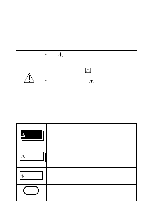
Safety Symbols
This manual contains information and warnings
essential for safe operation of the device and for
maintaining it in safe operating condition. Before
using the device, be sure to carefully read the
following safety notes.
The symbol printed on the device
indicates that the user should refer to a
corresponding topic in the manual
(marked with the
symbol) before
using the relevant function.
In the manual, the symbol indicates
particularly important information that the
user should read before using the
device.
The following symbols in this manual indicate the
relative importance of cautions and warnings.
Indicates that incorrect operation
DANGER
presents an extreme hazard that could
result in serious injury or death to the
user.
Indicates that incorrect operation
WARNING
presents a significant hazard that could
result in serious injury or death to the
user.
Indicates that incorrect operation
CAUTION
presents a possibility of injury to the user
or damage to the device.
NOTE
Indicates advisory items related to
performance or correct operation of the
device.
___________________________________________
Safety Notes
Page 7
____________________________________________________
iii
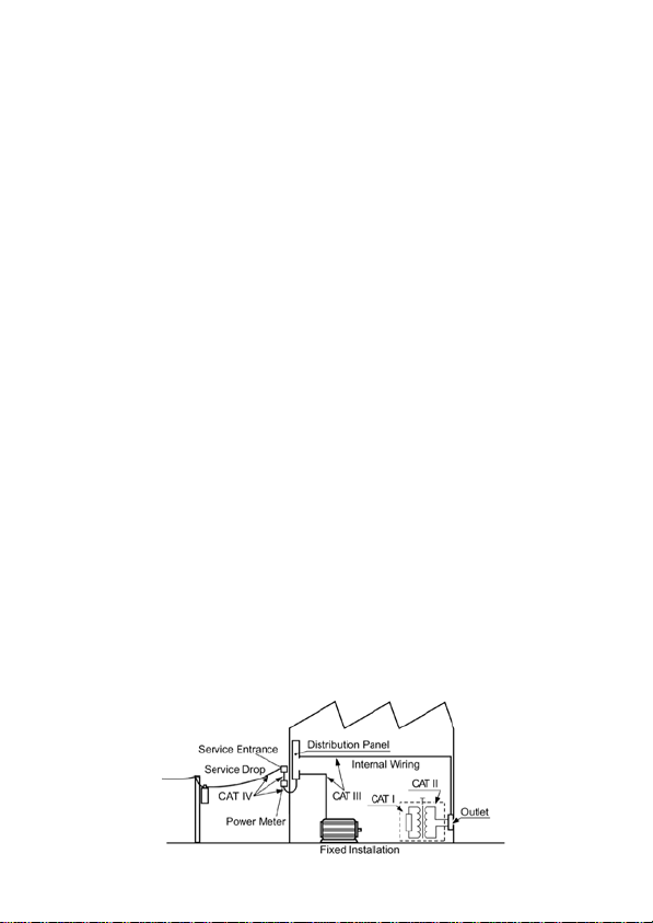
Overvoltage Categories (CAT)
This device conforms to the safety requirements for CAT I
measurement instruments.
To ensure safe operation of measurement instruments, IEC
60664 establishes safety standards for various electrical
environments, categorized as CAT I to CAT IV, and called
overvoltage categories. These are defined as follows.
CAT I : Secondary electrical circuits connected to an AC
electrical outlet through a transformer or similar
instrument.
CAT II : Primary electrical circuits in equipment
connected to an AC electrical outlet by a power
cord (portable tools, household appliances, etc.)
CAT III : Primary electrical circuits of heavy equipment
(fixed installations) connected directly to the
distribution panel, and feeders from the
distribution panel to outlets.
CAT IV : The circuit from the service drop to the service
entrance, and to the power meter and primary
overcurrent protection instrument (distribution
panel).
Higher-numbered categories correspond to electrical
environments with greater momentary energy, so a
measurement instrument designed for CAT III
environments can endure greater momentary energy than
one designed for CAT II. Using a measurement instrument
in an environment designated with a higher-numbered
category than that for which the instrument is rated could
result in a severe accident, and must be carefully avoided.
___________________________________________
Safety Notes
Page 8
iv
____________________________________________________
Note on Use
Follow these precautions to ensure safe operation
and to obtain the full benefits of the various
functions.
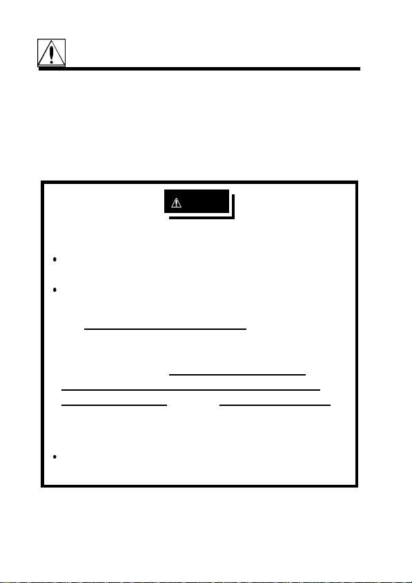
DANGER
To avoid short circuits and potentially lifethreatening hazards, follow these precautions.
Never attach the 3273 to a circuit that operates
at more than 300V, or over bare conductors.
While the core section is open, and when
conductors being measured carry in excess of
the safe voltage level (SELV-E) and not more
than 300 V, make sure that conductors to be
measured are insulated with material
conforming to (1) Overvoltage Category I,(2)
Basic Insulation Requirements for Working
Voltages of 300 V, and (3) Pollution Degree 2.
For safeties sake, never use this sensor on
bare conductors. The core and shield case are
not insulated.
Be careful to avoid damaging the insulation
surface while taking measurements.
___________________________________________
Note on Use
Page 9

____________________________________________________
DANGER
This device is made for use with the 3272
POWER SUPPLY. It is possible to use a power
supply other than the 3272, provided that the
connector and pin assignments match, and that
voltage and other electrical specifications are
satisfied. In the interest of safety, make sure
that the power supply has a protective earthing
with double-insulation construction.
Make sure that the waveform measuring
equipment connected to this device's output
terminal (BNC) is equipped with a protective
earthing with double-insulation construction.
To avoid electric shock, do not touch the
portion beyond the barrier during use.
If the waveform measuring instrument being
connected to the output terminal (BNC) on this
device is equipped with any other measurement
terminals, take the following precautions to
ensure that the other instrument does not form
a bridge between the probe and any hazardous
live of a part.
1. Isolate the terminal to which the probe is
connected from other terminals on the
measuring instrument using basic insulation
conforming to the overvoltage category,
working voltage, and pollution degree
requirements of the circuit being tested.
v
___________________________________________
Note on Use
Page 10

vi
____________________________________________________
DANGER
2. If basic insulation requirements cannot be
met between the terminal to which this device
is connected and other terminals of the
measuring instrument, make sure that the
voltage input to the measurement terminal
does not exceed the safe voltage level (SELVE).
3. Read and observe all warnings and
precautions relating to electrical safety for the
measuring instrument being connected to the
probe.
Refer to the following standards regarding the
meanings of underlined terms.
IEC61010-1
IEC61010-2-031
IEC61010-2-032
___________________________________________
Note on Use
Page 11
____________________________________________________
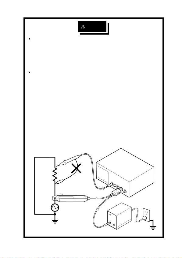
DANGER
vii
Be sure to observe all operating precautions for
the waveform monitoring instrument
(oscilloscope or recorder) and other
measurement instruments to which this device
is connected
When using a measurement instrument that
does not p rovide isolation between its input
terminals and chassis or other input terminals,
please pay attention to the following points.
If a signal is applied to an input terminal other
than that to which this device is connected, do
not connect the ground-side terminal to any
non-ground potential. Otherwise, short-circuit
current will flow through the 3272 or this device
from the ground terminal, which could cause an
electrical accident or damage.
___________________________________________
Note on Use
Page 12

viii
____________________________________________________
WARNING
Do not allow the device to get wet, and do not
take measurements with wet hands. This may
cause an electric shock.
CAUTION
To avoid damage to the device, protect it from
vibration or shock during transport and handling,
and be especially careful to avoid dropping.
Do not store or use the device where it could be
exposed to direct sunlight, high temperature or
humidity, or condensation. Under such conditions,
the device may be damaged and insulation may
deteriorate so that it no longer meets
specifications.
Before using the device the first time, verify that it
operates normally to ensure that the no damage
occurred during storage or shipping. If you find any
damage, contact your dealer or Hioki
representative.
This device is not designed to be entirely water- or
dust-proof. To avoid damage, do not use it in a wet
or dusty environment.
The sensor head is a precision assembly including
a molded component, a ferrite core, and a Hall
effect element. It may be damaged if subjected to
sudden changes in ambient temperature, or
mechanical strain or shock, and therefore great
care should be exercised in handling it.
___________________________________________
Note on Use
Page 13

____________________________________________________
CAUTION
ix
The matching surfaces of the sensor head are
precision ground, and should be treated with care.
If these surfaces are scratched, performance may
be impaired.
Measurements are degraded by dirt on the mating
surfaces of the sensor head, so keep the surfaces
clean by gently wiping with a soft cloth.
To avoid damaging the sensor cable and power
supply cable, do not bend or pull the cables.
When the power is on, keep the core section of the
sensor closed, except when clamping them onto
the conductor to be measured. The facing surface
of the core section can be scratched while it is
open.
NOTE
Correct measurement may be impossible in the
presence of strong magnetic fields, such as near
transformers and high-current conductors, or in
the presence of strong electromagnetic fields such
as near radio transmitters.
___________________________________________
Note on Use
Page 14

x
____________________________________________________
Service / Maintenance
To clean the device, wipe it gently with a soft
cloth moistened with water or mild detergent.
Never use solvents such as benzene, alcohol,
acetone, ether, ketones, thinners or gasoline, as
they can deform and discolor the case.
If damage is suspected, contact your dealer or
Hioki representative.
When sending the device for repair, pack
carefully to prevent damage in transit. Include
cushioning material so the 3273 cannot move
within the package. Be sure to include details of
the problem. Hioki cannot be responsible for
damage that occurs during shipment.
___________________________________________
Note on Use
Page 15

____________________________________________________
Chapter 1
Overview
1.1 Product Overview
This device can be directly connected to a BNC
input connector of a waveform measuring
instrument such as an oscilloscope or recorder, and
by clamping on a conductor to be measured, allows
the current waveform to be easily captured.
1.2 Features
Highly accurate current detection
Easy current measurement
Broadband frequency characteristics DC to 50
MHz
Compact and permits measurement of low current
levels
Easy protect function at excessive input
Unique HIOKI development of thin film Hall
effect element
1
_______________________________________________
Chapter 1 Overview
Page 16

2
____________________________________________________
1.3 Names of Parts
External view
Current direction
indication
2
8
1
"UNLOCK" indication
Sensor cable
5
Sensor Terminator
3
Power supply
cable
6
7
4
_______________________________________________
Chapter 1 Overview
Page 17

____________________________________________________
1.4 Parts of the Sensor
1. Opening lever
Operating lever for opening the sensor head. Always
use this lever to open the sensor head.
2. Sensor head
This clamps the conductor being measured, and
carries out the actual current measurement. It is a
precision assembly including a molded component, a
ferrite core, and a Hall effect element. It may be
damaged if subjected to sudden changes in ambient
temperature, or mechanical strain or shock, and
therefore great care should be exercised in handling
it.
3. Demagnetizing switch (DEMAG)
This demagnetizes the core if it has been magnetized
by switching the power on and off, or by an excessive
input. Always carry out demagnetizing before
measurement.
The demagnetizing process takes about one second.
During demagnetizing, a demagnetizing waveform is
output.
4. Zero adjustment dial (ZERO ADJ)
Use the zero adjustment dial to correct for the effect of
a voltage offset or temperature drift on the device.
When beginning measurement, after demagnetizing
always carry out zero adjustment.
5. Coarse adjustment trimmer
Use this only when adjustment is not possible within
the range of the zero adjustment dial. Use a
nonconductive screwdriver (e.g., ceramic driver) for
adjustment.
3
_______________________________________________
Chapter 1 Overview
Page 18

4
____________________________________________________
6. Output connector
The current waveform of the measured conductor is
output at a constant rate (0.1 V/A).
Connect to the BNC input connector of the waveform
measuring instrument.
NOTE
7. Power plug
8. Barrier
The output of this device is terminated internally.
Use a high-impedance input to the measuring
instrument. With an input impedance of 50Ω,
accurate measurement is not possible.
If using BNC-banana plug adapters or similar to
connect to input terminals other than BNC
connectors, make sure the polarity is correct.
Turn the collar until it clicks, and check that it is
locked securely.
Connect this to the 3272 POWER SUPPLY
receptacle to supply power to the sensor terminator.
This structure reduces the likelihood of touching the
conductor while testing, and indicates the limit of
safe physical contact. Avoid touching the clamp in
front of the barrier when clamping or measuring.
_______________________________________________
Chapter 1 Overview
Page 19

____________________________________________________
Chapter 2
Specifications
2.1 Product Specifications
Guaranteed at 23
power has been on for 30 minutes.
Frequency
range
Rise time
Maximum
continuous input
range
Maximum peak
current value
Output voltage
rate
Amplitude
accuracy
Noise
Input impedance
Temperature
coefficient for
sensitivity
DC to 50 MHz (-3 dB) (Characteristics
shown in Fig. 1)
7nsorless
15 A
Derating according to frequency shown
in Fig. 2
Non-continuous 30 A peak; at pulse
width
0.1 V/A
0.5% rdg. 1mV
(DC, and 45 to 66 Hz, input within
continuous maximum input range)
Equivalent to 2.5 mA rms or less (for 20
MHz band measuring instrument)
(Characteristics shown in Fig.3)
2% or less (within a range of 0 to 40
, within a range of 32 to 104 )
(73
±5
10µs, 50 A peak
±9
) after the
5
_______________________________________________
Chapter 2 Specifications
Page 20

6
____________________________________________________
Maximum rated
power
Rated supply
voltage
Operating
temperature and
humidity range
Storage
temperature and
humidity range
Location for use
Period of
guaranteed
accuracy
Effect of
external
magnetic fields
Maximum rated
voltage to earth
Diameter of
measurable
conductors
Cable lengths
External
dimensions
3VA
12 V 1V
0to40 (32 to 104 ), 80 %RH or
less (no condensation)
10 to 50 (14 to 122 ), 80 %RH or
-
less (no condensation)
Indoor, altitude up to 2000 m (6562 feet)
1 year (Opening/Closing up to 10,000
times)
Equivalent to a maximum of 20 mA (in
a 60 Hz,400 A/m AC current magnetic
field)
300 V, CAT I (insulated conductor)
5mmdia.
0.2" dia.
Sensor cable Approx. 1.5 m (59.0")
Power supply cable Approx. 1 m (39.4")
Sensor
Approx. 175Wx18Hx40Dmm
Approx. 6.89"Wx0.71"Hx1.58"D
Terminator
Approx. 27Hx55Wx18D mm
Approx. 1.06"Wx2.17"Hx0.71"D
_______________________________________________
Chapter 2 Specifications
Page 21

____________________________________________________
Mass
Accessories
Approx. 230 g
Approx. 8.1 oz.
Instruction manual, soft case
2.2 Standards Applying
7
Safety
EMC
]
V
1
=
B
d
0
[
e
d
u
t
i
l
p
m
A
EN61010-2-032:1995
Overvoltage category I (anticipated
transient overvoltage 1500 V),
Pollution Degree 2
EN61326:1997+A1:1998+A2:2001
Frequency [Hz]
Figure1 Frequencycharacteristics
_______________________________________________
Chapter 2 Specifications
Page 22

8
____________________________________________________
]
A
[
t
n
e
r
r
u
c
t
u
p
n
i
m
u
m
i
x
a
M
Frequency [Hz]
Figure2 Derating according to frequency
]
Ω
[
e
c
n
a
d
e
p
m
i
t
u
p
n
I
Figure3 Input impedance (Characteristics)
Frequency [Hz]
_______________________________________________
Chapter 2 Specifications
Page 23

____________________________________________________
Chapter 3
Measurement
Procedure
3.1 Notes on Use
DANGER
To avoid short circuits and potentially lifethreatening hazards, follow these precautions.
Never attach the 3273 to a circuit that operates
at more than 300V, or over bare conductors.
While the core section is open, and when
conductors being measured carry in excess of
the safe voltage level (SELV-E) and not more
than 300 V, make sure that conductors to be
measured are insulated with material
conforming to (1) Overvoltage Category I,(2)
Basic Insulation Requirements for Working
Voltages of 300 V, and (3) Pollution Degree 2.
For safeties sake, never use this sensor on
bare conductors. The core and shield case are
not insulated.
Be careful to avoid damaging the insulation
surface while taking measurements.
9
_______________________________________________
3 Measurement Procedure
Chapter
Page 24

10
____________________________________________________
DANGER
This device is made for use with the 3272
POWER SUPPLY. It is possible to use a power
supply other than the 3272, provided that the
connector and pin assignments match, and that
voltage and other electrical specifications are
satisfied. In the interest of safety, make sure
that the power supply has a protective earthing
with double-insulation construction.
Make sure that the waveform measuring
equipment connected to this device's output
terminal (BNC) is equipped with a protective
earthing with double-insulation construction.
To avoid electric shock, do not touch the
portion beyond the barrier during use.
If the waveform measuring instrument being
connected to the output terminal (BNC) on this
device is equipped with any other measurement
terminals, take the following precautions to
ensure that the other instrument does not form
a bridge between the probe and any hazardous
live of a part.
1. Isolate the terminal to which the probe is
connected from other terminals on the
measuring instrument using basic insulation
conforming to the overvoltage category,
working voltage, and pollution degree
requirements of the circuit being tested.
_______________________________________________
Chapter 3 Measurement Procedure
Page 25

____________________________________________________
DANGER
11
2. If basic insulation requirements cannot be
met between the terminal to which this device
is connected and other terminals of the
measuring instrument, make sure that the
voltage input to the measurement terminal
does not exceed the safe voltage level (SELVE).
3. Read and observe all warnings and
precautions relating to electrical safety for the
measuring instrument being connected to the
probe.
Refer to the following standards regarding the
meanings of underlined terms.
IEC61010-1
IEC61010-2-031
IEC61010-2-032
_______________________________________________
Chapter 3 Measurement Procedure
Page 26

12
____________________________________________________
DANGER
Be sure to observe all operating precautions for
the waveform monitoring instrument
(oscilloscope or recorder) and other
measurement instruments to which this device
is connected
When using a measurement instrument that
does not p rovide isolation between its input
terminals and chassis or other input terminals,
please pay attention to the following points.
If a signal is applied to an input terminal other
than that to which this device is connected, do
not connect the ground-side terminal to any
non-ground potential. Otherwise, short-circuit
current will flow through the 3272 or this device
from the ground terminal, which could cause an
electrical accident or damage.
_______________________________________________
Chapter 3 Measurement Procedure
Page 27

____________________________________________________
13
3.2 Preparations for Measurement
(1) Have the 3272 POWER SUPPLY, and oscilloscope
or recorder for waveform measurement ready.
CAUTION
Before turning on the power, make sure that the
voltage of the power supply being used matches the
supply voltage indicated on the rear panel of the
3272.
(2) Turn the power switch off and connect the power
cord.
(3) Connect the power plug of the 3273 to the power
receptacle of the 3272.
(4) Turn the 3272 power switch on, and check that the
front panel power indicator lights.
_______________________________________________
Chapter 3 Measurement Procedure
Page 28

14
____________________________________________________
3.3 Demagnetizing and Zero Adjustment
NOTE
The output of this device is terminated internally.
Use a high-impedance input to the measuring
instrument. With an input impedance of 50Ω,
accurate measurement is not possible.
(1) With the waveform measurement instrument input at
ground, adjust the trace to the zero position.
(2) Set the input coupling of the waveform measurement
instrument to DC.
(3) Connect the output connector of the 3273 to the
input connector of the waveform measurement
instrument. Turn the collar until it clicks, and check
that it is locked securely.
_______________________________________________
Chapter 3 Measurement Procedure
Page 29

____________________________________________________
g
CAUTION
15
When disconnecting the output connector, be sure
to release the lock, then pull the connector.
Forcibly pulling the connector without releasing the
lock, or pulling on the cable will result in damage to
the terminator.
If using BNC-banana plug adapters or similar to
connect to input terminals other than BNC
connectors, make sure the polarity is correct.
Do not demagnetize while the 3273 is clamping a
conductor to be measured. Demagnetizing causes
current to flow into the conductor, which may
damage parts in the circuit to be measured.
Demagnetizin
Conductor
Check that the conductor being measured is not
clamped when supplying power to the 3273 for the
same reason. Demagnetized waveforms are
generated when supplying electric power.
(4) Without clamping the conductor to be measured,
press the opening lever until the "UNLOCK"
indication disappears, and check that the sensor
head is properly closed.
(5) Press the demagnetizing switch (DEMAG) on the
terminator.
(6) Turn the zero adjustment dial on the terminator, to
adjust the trace to the zero position.
_______________________________________________
Chapter 3 Measurement Procedure
Page 30

16
____________________________________________________
(7) If zero adjustment is not possible in step 6, turn the
coarse adjustment trimmer to bring the trace within
the range of adjustment by the zero adjustment dial.
3.4 Measurement Procedure
(1) Check that the system is safe, and that the
preparations described in the preceding section have
been carried out.
(2) Pull the sensor opening lever, so that the sensor
head opens.
Opening lever
(3) Align the sensor so that the current direction
indication corresponds to the direction of current
flow through the conductor to be measured, and
clamp so that the conductor is in the center of the
sensor aperture.
(4) Press the opening lever on the sensor head until the
"UNLOCK" indication disappears, and check that
the opening lever is firmly locked and the sensor
head securely closed.
_______________________________________________
Chapter 3 Measurement Procedure
Page 31

____________________________________________________
17
(5) It is now possible to monitor the current
waveform. The output rate of the 3273 is 0.1 V/A.
The current sensitivity can be derived from the
voltage sensitivity of the waveform measurement
instrument. For example, if the voltage sensitivity is
10 mV/division, the current sensitivity is 100
mA/division.
・ When using the 3273, note that two clamp-on
NOTE
probes may not be used simultaneously with the
3272 POWER SUPPLY, depending on the current
to be measured.
・ The current consumption of clamp-on probes
depends on the current to be measured. Confirm
that the total current consumption of the clamp-on
probes does not exceed the rated output current of
the 3272. See Figure 1.
600
500
400
300
200
current consumption (mA)
100
0
0 1020304050
AC(f=50Hz)
DC
Fig.1
Current consumption* vs. current to be measured(typical)
*The sum total of a positive and negative current consumption
_______________________________________________
Chapter 3 Measurement Procedure
Page 32

18
____________________________________________________
WARNING
The maximu m continuous input range is based
on heat that is internally generated during
measurement. Never input current in excess of
this level. Exceeding the rated level may result
in damage to the probe.
The maximum continuous input range varies
according to the frequency of the current being
measured. See the figures in 2.1, "Product
Specifications"
If excess current is input, generated heat
activates a built-in safety function that blocks
normal output. If this happens, remove the
input immediately (remove the sensor from the
conductor being measured, or reduce the input
current to zero). Wait until the sensor has had
sufficient time to cool before resuming
operation.
Even if the input current does not exceed the
rated continuous maximum, continuous input
for an extended period of time may result in
activation of the safety circuit to prevent
damage resulting from heating of the sensor.
At high ambient temperatures, the built-in safety
circuit may activate at current input levels
below the rated continuous maximum.
Continuous input of current exceeding the rated
maximum or repeated safety circuit activation
will degrade performance of the safety circuit,
possibly resulting in damage to the device.
_______________________________________________
Chapter 3 Measurement Procedure
Page 33

____________________________________________________
WARNING
19
The probe is rated for maximum input under
two conditions in addition to the input
maximums shown in the "Product
Specifications." These are (1) 30 Apeak, for
non-continuous input, and (2) 50 Apeak for
pulse widths 10µs. (1) indicates an upper
waveform response limit of 30 Apeak. Use the
sensor at RMS current input levels that are
within the rated continuous maximums. (2)
indicates the upper response limit for a single
input pulse.
When opening the sensor head of the probe, be
sure to operate with the opening lever. If an
upper core is forced to open, when the sensor
head is locked, the open-close mechanism can
Do not press
NOTE
Upper core
The output of this device is terminated internally.
Use a waveform measurement instrument with an
Lock state
input impedance of at least 1 MΩ.
Immediately after powering on, this device may be
subject to an appreciable offset drift due to the
effect of self-heating. To counteract this, allow the
device to warm up for about 30 minutes before
carrying out measurement.
_______________________________________________
Chapter 3 Measurement Procedure
Page 34

20
____________________________________________________
NOTE
When performing continuous measurements, it is
necessary to be aware that the offset voltage drifts,
depending on factors such as the ambient
temperature.
Under certain circumstances, oscillation may occur
if the probe is connected to the 3272 POWER
SUPPLY while the power supply is on. This does
not indicate a malfunction. Oscillation can be
stopped and operation restored to normal by
opening and closing the sensor head.
Depending on the measured current frequency,
however some sound may be produced by
resonance, it has no effect on measurements.
The reading may be affected by the position within
the clamp aperture of the conductor being
measured. The conductor should be in the center of
the clamp aperture.
When carrying out measurement, press the opening
lever until the "UNLOCK" indication disappears,
and check that the sensor head is properly closed. If
the sensor head is not properly closed, accurate
measurement will not be possible.
At high frequencies, common mode noise may
affect measurements taken on the high voltage side
of circuits. If this occurs, reduce the frequency
range of the waveform measuring instrument, or
clamp onto the low-voltage side of the circuit, as
appropriate.
_______________________________________________
Chapter 3 Measurement Procedure
Page 35

____________________________________________________
21
H
NOTE
Power
source
Load
L
Accurate measurement may be impossible in
locations subject to strong external magnetic
fields, such as transformers and high-current
conductors, or in locations subject to strong
external electric fields, such as radio transmission
equipment.
_______________________________________________
Chapter 3 Measurement Procedure
Page 36

22
____________________________________________________
_______________________________________________
Chapter 3 Measurement Procedure
Page 37

Page 38

 Loading...