

Page 1

Instruction Manual
99 Washington Street
Melrose, MA 02176
Phone 781-665-1400
Toll Free 1-800-517-8431
Visit us at www.TestEquipmentDepot.com
3272
POWER SUPPLY
December 2014 Revised edition 12 3272A981-12 14-12H
Page 2

Contents
Introduction i
Inspection
Notes on Safety
Precautions
i
ii
vi
Chapter 1 Overview
1.1 Product Overview 1
1.2 Names of Parts
Chapter 2 Specifications 5
2.1 Product Specifications 5
2.2 Standards Applying
Chapter 3 Measurement Procedure 7
3.1 Preparations 8
3.2 Measurement Procedure
Chapter 4 Description of Parts 13
4.1 Power Supply Receptacle 13
4.2 How to Change the Power Supply Fuse
and Change the Power Supply Voltage
3272A981-12
1
2
6
9
13
Page 3

―――――――――――――――――――――――――――
Introduction
Thank you for purchasing the HIOKI "Model 3272
POWER SUPPLY."
To obtain maximum performance from the product,
please read this manual first, and keep it handy for
future reference.
Inspection
When you receive the product, inspect it carefully to
ensure that no da mage occurred during shipping. If
damage is evident, or if it fails to operate according
to the specifications, contact your dealer or Hioki
representative.
Supplied accessories
Power cord 1
Instruction manual 1
Spare fuse 1
100 V, 120 V: F1.0 AL/250 V, 20 mm x 5 mm dia.
220 V, 240 V: F0.5 AL/250 V, 20 mm x 5 mm dia.
i
――――――――――――――――――――――――
Introduction
Page 4
ii
―――――――――――――――――――――――――――
Notes on Safety
WARNING
This product is designed to comply with IEC
61010 Safety Standards, and has been thoroughly
tested for safety prior to shipment. However,
mishandling during use could result in injury or
death, as well as damage to the product. Using
the product in a way not described in this manual
may negate the provided safety features.
Be certain that you understand the instructions
and precautions in the manual before use. W e
disclaim any responsibility for accidents or
injuries not resulting directly from product
defects.
――――――――――――――――――――――――
Notes on Safety
Page 5
―――――――――――――――――――――――――――
iii
Safety Symbols
This manual contains information and warnings
essential for safe operation of the product and for
maintaining it in safe operating condition. Before
using it, be sure to carefully read the following
safety precautions.
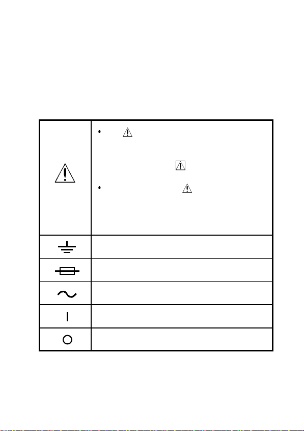
The symbol printed on the product
indicates that the user should refer to a
corresponding topic in the manual
(marked with the
symbol) before
using the relevant function.
In the manual, the symbol indicates
particularly important information that
the user should read before using the
product.
Indicates a grounding terminal.
Indicates a fuse.
Indicates AC (Alternating Current).
Indicates the ON side of the power
switch.
Indicates the OFF side of the power
switch.
――――――――――――――――――――――――
Notes on Safety
Page 6
iv
―――――――――――――――――――――――――――
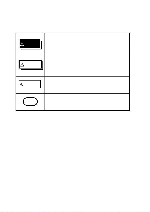
The following symbols are used in this Instruction
Manual to indicate the relative importance of
cautions and warnings.
Indicates that incorrect operation
DANGER
presents an extreme hazard that could
result in serious injury or death to the
user.
Indicates that incorrect operation
WARNING
presents a significant hazard that could
result in serious injury or death to the
user.
Indicates that incorrect operation
CAUTION
presents a possibility of injury to the
user or damage to the product.
Indicates advisory items related to
NOTE
performance or correct operation of the
product.
――――――――――――――――――――――――
Notes on Safety
Page 7
―――――――――――――――――――――――――――
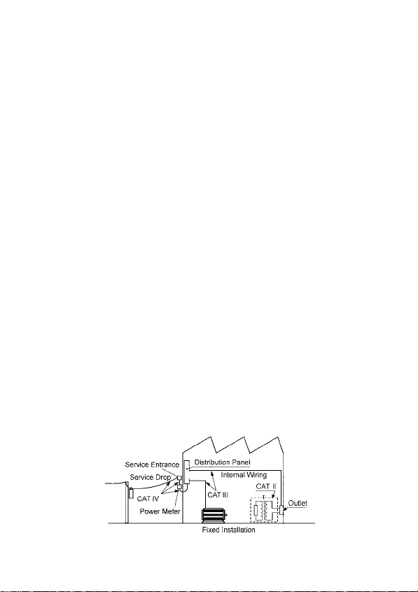
Measurement categories
To ensure safe operation of measurement products,
IEC 61010 establishes safety standards for various
electrical environments, categorized as CAT II to
CAT IV, and called measurement categories.
CAT II : Primary electrical circuits in equipment
connected to an AC electrical outlet by a
power cord (portable tools, household
appliances, etc.) CAT II covers directly
measuring electrical outlet receptacles.
CAT III : Primary electrical circuits of heavy
equipment (fixed installations) connected
directly to the distribution panel, and
feeders from the distribution panel to
outlets.
CAT IV : The circuit from the service drop to the
service entrance, and to the power meter
and primary overcurrent protection device
(distribution panel).
Using a measurement product in an environment
designated with a higher-numbered category than
that for which the product is rated could result in a
severe accident, and must be carefully avoided.
Use of a measurement instrument that is not CATrated in CAT II to CAT IV measurement
applications could result in a severe accident, and
must be carefully avoided.
v
――――――――――――――――――――――――
Notes on Safety
Page 8

vi
―――――――――――――――――――――――――――
Precautions
Follow these precautions to ensure safe operation
and to obtain the full benefits of the various
functions.
Preliminary Check
Before using the product for the first time, verify
that it operates normally to ensure that no damage
occurred during storage or shipping. If you find any
damage, contact your dealer or Hioki representative.
――――――――――――――――――――――――
Precautions
Page 9
―――――――――――――――――――――――――――
vii
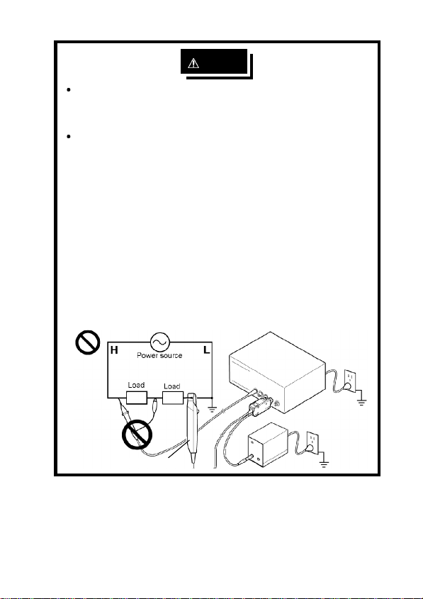
DANGER
To avoid accidents, when using other
measurementdevices with this one, observe the
usage precautions described for each device.
When using a measurement instrument that
does not provide isolation between its input
terminals and chassis or other input terminals,
please pay attention to the following points.
If a signal is applied to an input terminal other
than that to which the current probe is
connected, do not connect the ground-side
terminal to any non-ground potential.
Otherwise, short-circuit current will flow
through the current probe or this device from
the ground terminal, which could cause an
electrical accident or damage.
Current Probe
――――――――――――――――――――――――
Precautions
Page 10

viii
―――――――――――――――――――――――――――
WARNING
To avoid electrical accidents and to maintain the
safety specifications of this instrument, connect
the power cord only to a 3-contact (two-conductor
+ ground) outlet.
CAUTION
To avoid damage to the product, protect it from
physical shock when transporting and handling. Be
especially careful to avoid physical shock from
dropping.
Do not store or use the product where it could be
exposed to direct sunlight, high temperature or
humidity, or condensation. Under such conditions,
the product may be damaged and insulation may
deteriorate so that it no longer meets
specifications.
To avoid damaging the power cord, grasp the plug,
not the cord, when unplugging the cord from the
power outlet.
This product is not designed to be entirely water- or
dust-proof. Do not use it in an especially dusty
environment, nor where it might be splashed with
liquid. This may cause damage.
――――――――――――――――――――――――
Precautions
Page 11

―――――――――――――――――――――――――――
ix
Maintenance & Service
To clean the product, wipe it gently with a soft
cloth moistened with water or mild detergent.
Never use solvents such as benzene, alcohol,
acetone, ether, ketones, thinners or gasoline, as
they can deform and discolor the case.
If the product seems to be malfunctioning, contact
your dealer or Hioki representative.
When sending the product for repair, pack
carefully to prevent damage in transit. Include
cushioning material so the instrument cannot
move within the package. Be sure to include
details of the problem.
Hioki cannot be responsible for damage that
occurs during shipment.
――――――――――――――――――――――――
Precautions
Page 12

―――――――――――――――――――――――――――
Chapter 1
Overview
1.1 Product Overview
This unit is the power supply dedicated to Models
3273-50, 3273, 3274, 3275, and 3276 Clamp on
Probe (hereafter referred to as thecurrent probe),
as well as Models CT6700 and CT6701 Current
Probe.
1
――――――――――――――――――――――――
Chapter 1 Overview
Page 13

2
―――――――――――――――――――――――――――
1.2 Names of Parts
External view
Power
indicator
Power supply receptacles
Front view
――――――――――――――――――――――――
Chapter 1 Overview
Page 14

―――――――――――――――――――――――――――
Power supply
connector Fuse holder
Power
switch
Voltage
window
On
Off
Grounding terminal
Rear view
3
――――――――――――――――――――――――
Chapter 1 Overview
Page 15

―――――――――――――――――――――――――――
Chapter 2
Specifications
2.1 Product Specifications
Compatible
sensors
Number of
power supply
connectors
Output voltage
Rated output
current
Ripple voltage
Load influence
Temperature
influence
Power supply
voltage
influence
Operating
temperature and
humidity range
3273-50, 3273, 3274, 3275, 3276 Clamp
On Probe and CT6700, CT6701 Current
Probe
2
12 V 0.5 V
600 mA (sum total of all channels and
all output voltages)
3 mVp-p or less (at rated output current)
Within output voltage limits indicated
above for current output in the range 0
to 600 mA.
Within output voltage limits indicated
above for ambient temperature in the
range 0 to 40
Within output voltage limits indicated
above for the rated power supply
voltage,
0to40 (32 to 104 ), 80% RH or
less (no condensation)
(32 to 104 ).
10%.
5
――――――――――――――――――――――――
Chapter 2 Specifications
Page 16

6
―――――――――――――――――――――――――――
10 to 50 (14 to 122 ), 80% RH or
Storage
temperature and
humidity range
Location for use
Rated supply
voltage
Rated supply
frequency
Maximum rated
power
External
dimensions
Mass
Accessories
-
less (no condensation)
Indoor,altitude up to 2000 m (6562 feet)
100 V AC (120, 220, and 240 V require
specification) (Voltage fluctuation of
10% from the rated supply voltage are
taken into account.)
50/60 Hz
20 VA
Approx. 73W x 110H x 186D mm
Approx. 2.87"W x 4.33"H x 7.32"D
Approx. 1.1 kg
Approx. 38.8 oz.
Power cord, Instruction manual,
Spare fuse
F1.0 AL/250 V, 20 mm x 5 mm dia.
(for 100 V and 120 V models)
or
F0.5 AL/250 V, 20 mm x 5 mm dia.
(for 220 V and 240 V models)
2.2 Standards Applying
Safety
EMC
――――――――――――――――――――――――
Chapter 2 Specifications
EN61010, Pollution Degree 2
EN 61326
EN 61000-3-2
EN 61000-3-3
Page 17

―――――――――――――――――――――――――――
Chapter 3
Measurement
Procedure
7
――――――――――――――――――――――――
Chapter 3 Measurement Procedure
Page 18

8
―――――――――――――――――――――――――――
3.1 Preparations
DANGER
To avoid accidents, when using other
measurementdevices with this one, observe the
usage precautions described for each device.
When using a measurement instrument that
does not provide isolation between its input
terminals and chassis or other input terminals,
please pay attention to the following points.
If a signal is applied to an input terminal other
than that to which the current probe is
connected, do not connect the ground-side
terminal to any non-ground potential.
Otherwise, short-circuit current will flow
through the current probe or this device from
the ground terminal, which could cause an
electrical accident or damage.
Current Probe
――――――――――――――――――――――――
Chapter 3 Measurement Procedure
Page 19

―――――――――――――――――――――――――――
WARNING
Before turning the p roduct on, make sure the
supply voltage matches that indicated on its
power c onnector. Connection to an improper
supply voltage may damage the product and
present an electrical hazard.
(1) Turn the power switch off and connect the power
cord.
(2) Connect the power plug of the sensor to be used to
the power receptacle of the 3272.
(3)
Turn the 3272 power switch on, and check that the
front panel power indicator lights.
3.2 Measurement Procedure
See the 3273-50, 3273, 3274, 3275, 3276, CT6700
or CT6701 instruction manual.
NOTE
Make sure the sum of the current consumption of
the connected current probe does not exceed the
rated output current of the 3272 (See Fig.1).
When using the 3272 with Model 3273-50, 3273,
3274, 3275, 3276, CT6700 or CT6701 in general
only one current probe may be connected.
However, depending on the current level of the
object under test, two current probes may be
connected simultaneously.
The current consumption of a current probe is
dependent upon the current level of the object under
test.
9
――――――――――――――――――――――――
Chapter 3 Measurement Procedure
Page 20

10
―――――――――――――――――――――――――――
600
)
A
500
m
(
n
o
400
i
t
p
m
300
u
s
n
200
o
c
t
n
100
e
r
r
u
0
c
0 1020304050
AC(f=50Hz)
DC
(1) 3273-50 current (A)
600
)
A
500
m
(
n
o
400
i
t
p
m
300
u
s
n
o
200
c
t
n
100
e
r
r
u
c
0
0 100 200 300
AC(f=50Hz)
DC
(2) 3274 current (A)
600
)
A
500
m
(
n
400
o
i
t
p
300
m
u
s
n
200
o
c
t
100
n
e
r
r
u
0
c
0 100 200 300 400 500 600 700
AC(f=50Hz)
DC
(3) 3275 current (A)
――――――――――――――――――――――――
Chapter 3 Measurement Procedure
Page 21

―――――――――――――――――――――――――――
600
)
A
500
m
(
n
400
o
i
t
p
300
m
u
s
n
200
o
c
t
n
100
e
r
r
u
0
c
0 1020304050
AC(f=50Hz)
DC
11
(4) 3276 current (A)
600
)
A
500
m
(
n
400
o
i
t
p
300
m
u
s
200
n
o
c
100
t
n
e
0
r
r
u
0102030
c
AC(f=50Hz)
DC
(5) 3273 current (A)
――――――――――――――――――――――――
Chapter 3 Measurement Procedure
Page 22

12
―――――――――――――――――――――――――――
)
A
m
(
n
o
i
t
p
m
u
s
n
o
c
t
n
e
r
r
u
c
(6) CT6700, CT6701 current (A)
Fig.1
Current consumption* vs. current to be measured(typical)
*The sum total of a positive and negative current consumption
――――――――――――――――――――――――
Chapter 3 Measurement Procedure
Page 23

―――――――――――――――――――――――――――
13
Chapter 4
Description of Parts
4.1 Power Supply Receptacle
The pin assignment of the receptacle is shown in the
following.
1 Not used
12
43
4.2 How to Change the Power Supply
Fuse and Change the Power Supply
Voltage
2Ground
3-12V
4+12V
The power supply fuse for the 3272 unit, and the
power supply voltage selector, are housed in the
power input socket on the rear panel.
――――――――――――――――――――――――
Chapter 4 Description of Parts
Page 24

14
―――――――――――――――――――――――――――
WARNING
To avoid electric shock, turn off the power
switch and disconnect the current probe before
replacing the fuse.
Replace the fuse only with one of the specified
characteristics and voltage and current ratings.
Never use unspecified fuses and never use the
product after the fuse holder has shorted. This
will damage the product and cause injury.
Supply voltage
100 V, 120 V : F1.0 AL/250 V 20 mm x 5 mm
dia.
220 V, 240 V : F0.5 AL/250 V 20 mm x 5 mm
dia.
To change the fuse, or to alter the power supply
voltage setting, use the following procedure with
reference to the figures.
1. Turn the power switch off, and then remove the
power cord.
2. Using a slot head screwdriver or the like, bias
sideways the catch which holds the fuse holder into
the power input socket as shown in the figure, and
then remove the fuse holder.
3. When changing the power supply fuse:
Change the power supply fuse for a new one of the
same rating and specification.
When altering the power supply voltage setting:
(1) Remove the voltage selector from the fuse
holder, and reinsert it after having rotated it so
that the desired new power supply voltage
――――――――――――――――――――――――
Chapter 4 Description of Parts
Page 25

―――――――――――――――――――――――――――
15
setting appears in the voltage window as shown
in the figure.
Then recheck the setting value shown in the
voltage window. (The voltage display is upside
down and backwards.).
(2) Change the power supply fuse for a new one
whose rating and specification are appropriate
for the new power supply setting.
4. Replace the fuse holder by reinserting it into the
power input socket.
Power input socket
Screwdriver
Pry the catch with a
slot head screwdriver
or the like and remove
the fuse holder.
Fuse holder
――――――――――――――――――――――――
Chapter 4 Description of Parts
Page 26

16
―――――――――――――――――――――――――――
When altering the power
supply voltage setting:
Fuse holder
Voltage
selector
Remove the voltage
selector, rotate it so that
the figures which will
appear in the voltage
window represent the
voltage of the power
supply which will now be
used, and then replace
it.
When changing the power
supply fuse:
Fuse holder
Voltage window
――――――――――――――――――――――――
Chapter 4 Description of Parts
Page 27

Test Equipment Depot - 800.517.8431 - 99 Washington Street Melrose, MA 02176
TestEquipmentDepot.com
 Loading...