

Hioki 3256-50, 3256-51, 3257-50, 3257-51 Instruction Manual

INSTRUCTION MANUAL
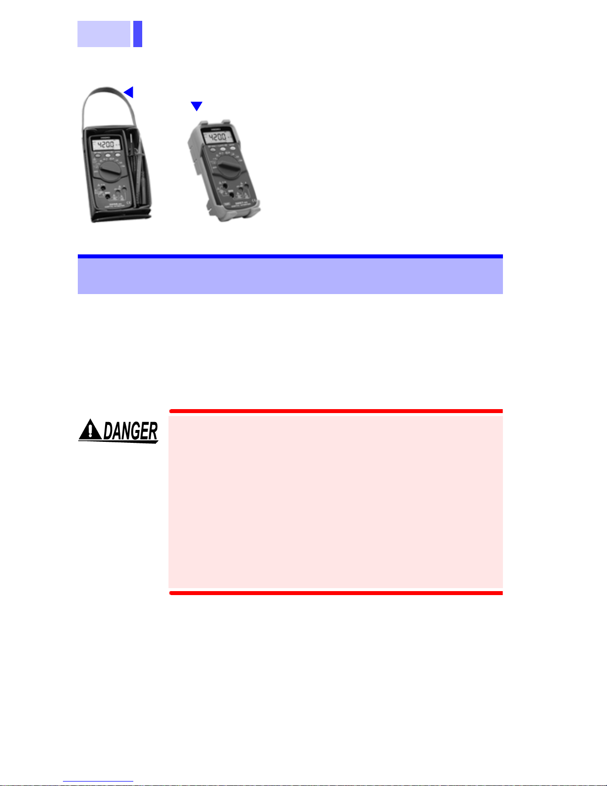
3256-50
3256-51
DIGITAL HiTESTER


i
Contents
Introduction .............................................................1
Inspection ............................................................... 1
Safety Notes ...........................................................2
Usage Notes........................................................... 6
Chapter 1 Overview 9
1.1 Product Overv iew ........................... ...... ..9
1.2 Features ..................................................9
1.3 Parts Names and Functions .................10
Chapter 2 Measurement Procedures 15
2.1 Voltage Meas urem en t........................... 16
2.2 Frequency Measurement...................... 18
2.3 Current Measurement........................... 19
2.4 Resistance Measurement..................... 22
2.5 Continuity Chec k............. ...... ...... .......... 23
2.6 Diode Check......................................... 24
Chapter 3 Additional Functions 25
3.1 HOLD AUTO Function ..........................25
3.2 HOLD Function .............. ...... .................26
3.3 Overflow Warning Function ..................27
3.4 Relative Display Function .....................28
3.5 Auto Power Save Function ................... 30
3.6 Voltage Detecti ng Func ti on ...................31
3.7 Dynamic Recording Function ................32
3.8 Memory Function ..................................33

ii
Chapter 4 Specificatio ns 35
4.1 General Specifications ..........................35
4.2 Accuracy ................................................39
Chapter 5 Maintena ce and Service 43
5.1 Replacing the Batteries and Fuses ........43
5.2 Cleaning ................................................45
5.3 Service ..................................................45

1
Introduction
Thank you for purchasing the HIOKI "3256-50/51
DIGITAL HiTESTER". To obtain maximum performance from the product, please read th is manual
first, and keep it handy for future reference.
Inspection
• When you receive the product, inspect it carefully
to ensure that no damage occurred during shipping. In particular, check the accessories, panel
switches, and connectors. If damage is evident, or
if it fails to operate according to the specifications,
contact your dealer or Hioki representative.
• Before using the product the first time, verify that it
operates normally to ensure that the no damage
occurred during storage or shipping. If you find any
damage, contact your dealer or Hioki representative.
• Before using the product, make sure that the insulation on the test leads is undamaged and that no
bare conductors are improperly exposed. Using
the product under such conditions could result in
electrocution. Replace the test leads and probes
with the specified Hioki Model 9207-10.
2
Accessories
3256-50
*1
3256-51
Safety Notes
This manual contains information and warnings
essential for safe operation of the product and for
maintaining it in safe operating condition. Before
using the product, be sure to carefully read the following safety notes.
9207-10 TEST LEAD .................. 1
*2
Instruction Manual....................... 1
R03 Manganese battery..............2
(Supplied with this product, for
monitor)
9378 CARRYING CASE
(3256-50 only)
Protective holster
*2
(3256-51only)
*1
This product is designed to conform to IEC
61010 Safety Standards, and has been thoroughly tested for safety prior to shipment.
However, mishandling during use could
result in injury or death, as well as damage to
the product. Be certain that you understand
the instructions and precautions in the manual before use. We disclaim any responsibility for accidents or injuries not resulting
directly from product defects.
3
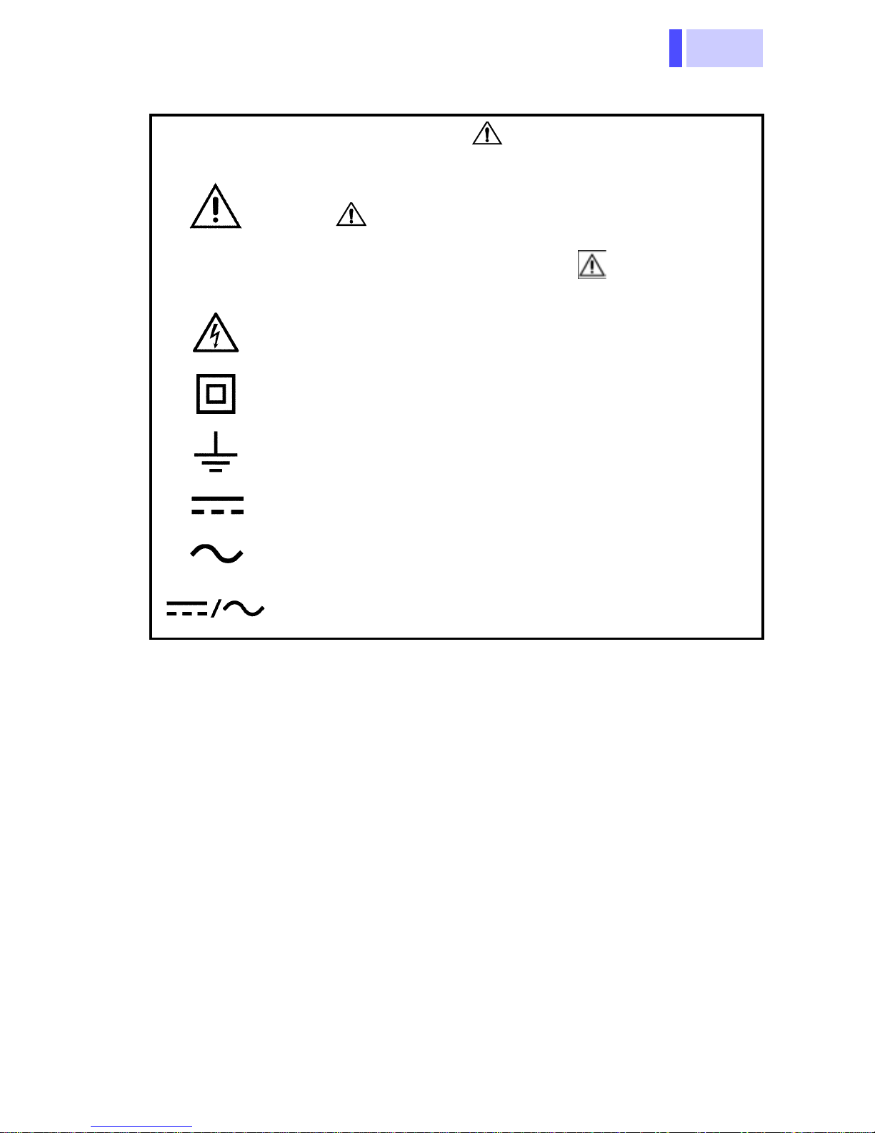
Safety Symbols
In the manual, the symbol indicates particularly important information that the user should
read before using the product.
The symbol printed on the product indicates
that the user should refer to a corresponding topic
in the manual (marked with the symbol) before
using the relevant function.
Indicates that dangerous voltage may be present
at this terminal.
Indicates a double-insulated device.
Indicates a grounding terminal.
Indicates DC (Direct Current).
Indicates AC (Alternating Current).
Indicates DC (Direct Current) or AC (Alternating
Current).
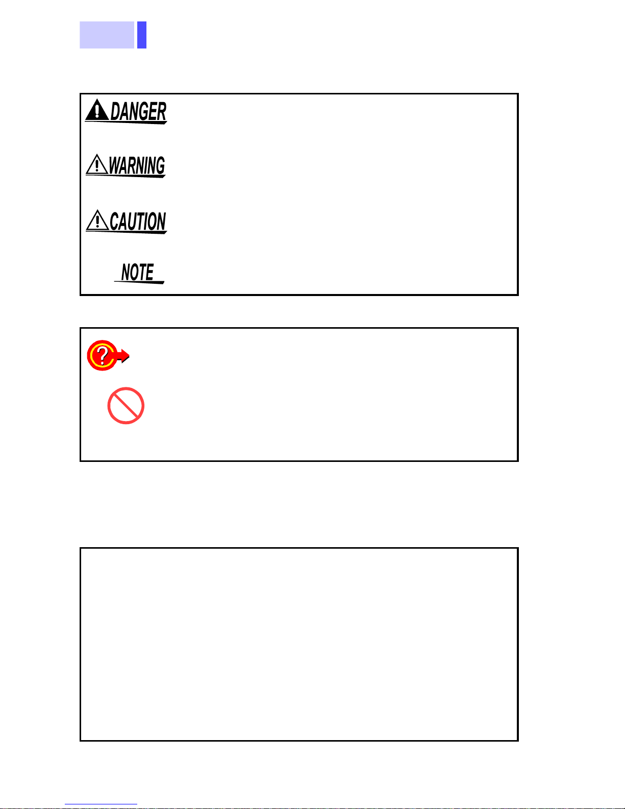
4
The following symbols in this manual indicate the
relative importance of cautions and warnings.
Indicates that incorrect operation presents an extreme hazard that could result in serious injury or
death to the user.
Indicates that incorrect operation presents a significant hazard that could result in serious injury or
death to the user.
Indicates that incorrect operation presents a possibility of injury to t he user or damage to the product.
Advisory items related to performance or correct
operation of the product.
Other Symbols
❖
Accuracy
f.s.
rdg.
Indicates the quick guide for operations
Indicates the prohibited action
Indicates the reference
We define measurement tolerances in terms of f.s.
(full scale), rdg. (reading) and dgt. (digit) values,
with the following meanings:
(maximum display value or scale length)
The maximum displayable value or the full length
of the scale. This is usually the maximum value of
the currently selected range.
(reading or displayed value)
The value currently being measured and indicated
on the measuring product.
(resolution)
dgt.
The smallest displayable unit on a digital measuring product, i.e., the input value that causes the
digital display to show a "1".
5
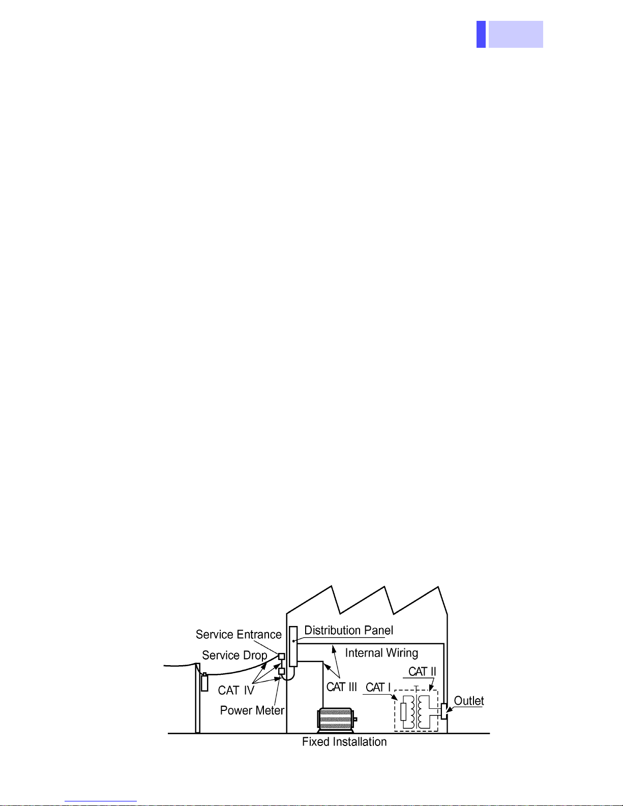
Measurement categories (Overvoltage categories)
This product complies with CATIII (600 V), CATII (1000 V) safety
requirements.
To ensure safe operation of measurement products, IEC 61010
establishes safety standards for various electrical environments,
categorized as CAT I to CAT IV, and called measurement categories. These are defined as follows.
CAT I
Secondary electrical circuits connected to an AC electrical outlet through a transformer or similar device.
Primary electrical circuits in equipment connected to
CAT II
an AC electrical outlet by a power cord (portable tools,
household appliances, etc.)
Primary electrical circuits of heavy equipment (fixed
CAT III
installations) connected directly to the distribution
panel, and feeders from the distribution panel to outlets.
The circuit from the service drop to the service en-
CAT IV
trance, and to the power meter and primary overcurrent protection device (distribution panel).
Higher-numbered categories correspond to electrical environments with greater momentary energy. So a measurement
device designed for CAT III environments can endure greater
momentary energy than a device designed for CAT II.
Using a measurement product in an environment designated
with a higher-numbered category than that for which the product
is rated could result in a sev ere accident, and mus t be carefully
avoided.
Never use a CAT I measuring product in CAT II, III, or IV environments.
The measurement categories comply with the Overvoltage Categories of the IEC60664 Standards.
6
Usage Notes
Follow these precautions to ensure safe operation
and to obtain the full benefits of the various functions.
• To avoid electric shock, do not allow the
product to get wet, and do not use it when
your hands are wet.
• Do not use the product where it may be
exposed to corrosive or combustible
gases. The product may be damaged or
cause an explosion.
7
Direct
-
st
-
n
n
sunlight
High temper
ature, high
humidity, du
Observe the following to avoid damage to the
product.
• Installation and Operating Environment
Between 0°C and 40°C; 80% RH or less;
indoors only. Howev er, it can be safely operated
at as low as -10°C.
• Do not store or use the product where it could
be exposed to direct sunlight, high tem perature
or humidity, or condensation. Under suc h conditions, the product may be damaged and insulation may deteriorate so that it no longer meets
specifications.
• This product is not designed to be entirely
water- or dust-proof. To avoid damage, do not
use it in a wet or dusty environment.
• Do not use the product near a device that generates a strong electromagnetic field or electro-
Electromag
etic radiatio
static charge, as these may cause erroneous
measurements.
• To avoid damage to the product, protect it from
vibration or shock during transport and handling,
and be especially careful to avoid dropping.
• Adjustments and repairs should be made only
Impact,
dropping
by technically qualified personnel.
• If the protective functions of the product are
damaged, either remove it from service or mark
it clearly so that others do not use it inadvertently.
• To avoid corrosion from battery leakage, remove
the batteries from the product if it is to be st ored
for a long time.

8
• Accurate measurement may be impossible in the
presence of strong magnetic fields, such as near
transformers and high-current conductors, or in
the presence of strong electromagnetic fields
such as near radio transmitters.
• To avoid battery depletion, turn the function
selector OFF after use (the Auto Power Save
feature consumes a small amount of current).
• The indicator appears when battery voltage
becomes low. Replace the batteries as soon as
possible.

9
1.1 Product Ov e r view
Overview Chapter 1
1.1 Product Overview
This measurement product is a multi-functional
digital multimeter capable of measuring DC and
AC voltages, DC and AC currents, and the resistance, checking the diode and continuity, and
detecting voltage.
1.2 Features
Compliance with CE marking requirements
The measurement product is designed to comply
with the international safety standard (IEC61010-
1) and EMC standards.
Safety-designed handy digital multimeter
The measurement product is equipped with testlead misinsertion preventive shutters and fast -acting fuses at the current measurement terminals.
Multi-functional and voltage detecting
• Live conductors can be examined safely and easily.
• The Hold Auto function allows measur ed v alue s to
be maintained by simply disconnecting the test
leads.
• The Hold function maintains the displayed value.
• The Memory function saves the held value displayed.
• The Recording function displays the maximum,
minimum, average, and currently measured values
selectively.
• The Relative function displays any discrepancy
from the reference.
1.3 Parts Names and Functions
10
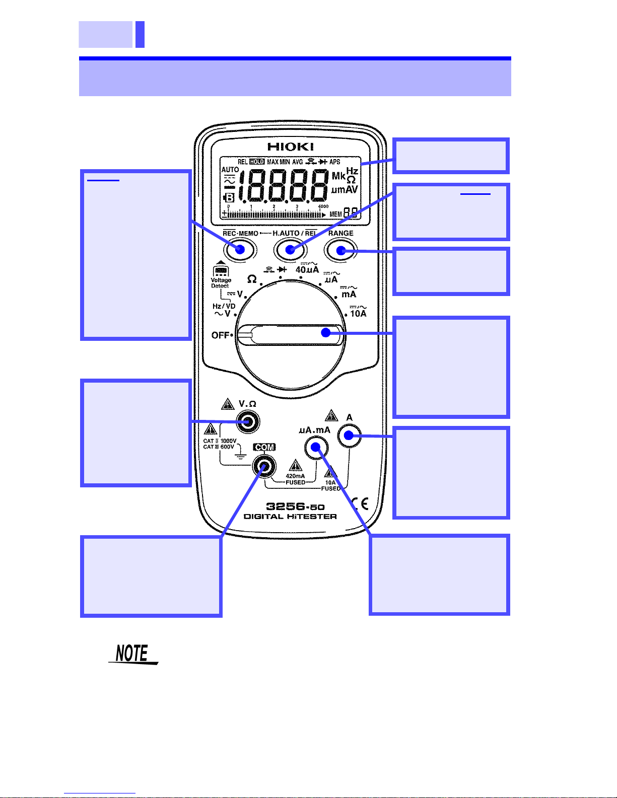
1.3 Parts Names and Functions
*: for details, see
the following
pages
REC•MEMO
Button
(Press this button
to change to the
function indi ca ted in blue.)
For other functions, see the following pages.
LCD display *
H.AUTO/REL
Button *
RANGE
Button *
V.Ω terminal
Terminal used to
measure volta ges and resistances
(red test lead)
COM terminal
Terminal com mon to
all functions
(black test lead)
The terminal shutter works together with the
function selector to prevent incorrect operation.
Note that if the function selector is toggled with
the test leads connected, the measurement
product may be damaged.
Function
Selector
(Selects functions
and turns the
power on/off)
A terminal
Terminal used to
measure currents
in 10-A mode
μA.mA terminal
Terminal used to
measure currents in
μA/mA mode
11
1.3 Parts Names and Functions
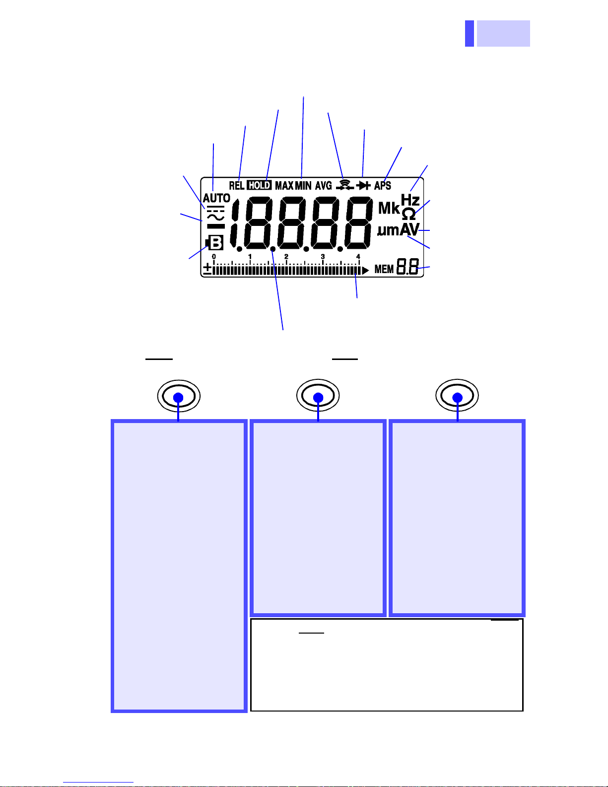
LCD(Display)
n
n
r
d
s
k
s
-
)
)
-
Indicates HOLD AUTO/
HOLD function
Indicates Relative functio n
Indicates Autorang ing
function
Indicates DC
voltage/current function
Indicates AC
voltage/current function
Indicates low
battery voltage
Lights up when the voltage
drops below the battery
accuracy guarantee voltage
(2.2±0.1 V)
REC•MEMO
Decimal point
Indicates Recording function
Indicates Continuity Check functio
Indicates Diode Check functio
Indicates Auto Powe
Save is enabl e
Frequency unit
Resistance and
continuity chec
units
Voltage and di
ode check unit
Current unit s
Indicates the
memory data
number
Bar-graph scale (42 dots)
Bar graph (with polarity indicator)
H.AUTO/REL RANGE
Changes to the function indicated in blue
Toggles between AC
and DC modes(Current measurement)
(page 19)
Recording function
(Displays MAX/MIN/
AVG)*1
(page 32)
Voltage Detecting
(page 31)
Memory Function
(page 33)
Cancels the Auto
Power Save function
*2
(page 30)
HOLD AUTO function
(Holds the measured
value)
(page 25)
Turns the HOLD
function on/off
Turns the Relative
function (displaying
the relative value) on/
off*1
*1: Press the button for at least 1 second (REC
and REL require the button to be pressed
for a longer time).
*2: Turn on the power while pressing the but-
ton, and hold the button down until a beep
ing sound is generated (power-on option).
*2
(page 26)
(page 28)
Changes the manual
range and selects
range
Changes the auto
range from the manu
al range*1
Changes the input
level
(Frequency fun cti on )
Calls data from mem
ory*2
(page 18
(page 34
1.3 Parts Names and Functions
12
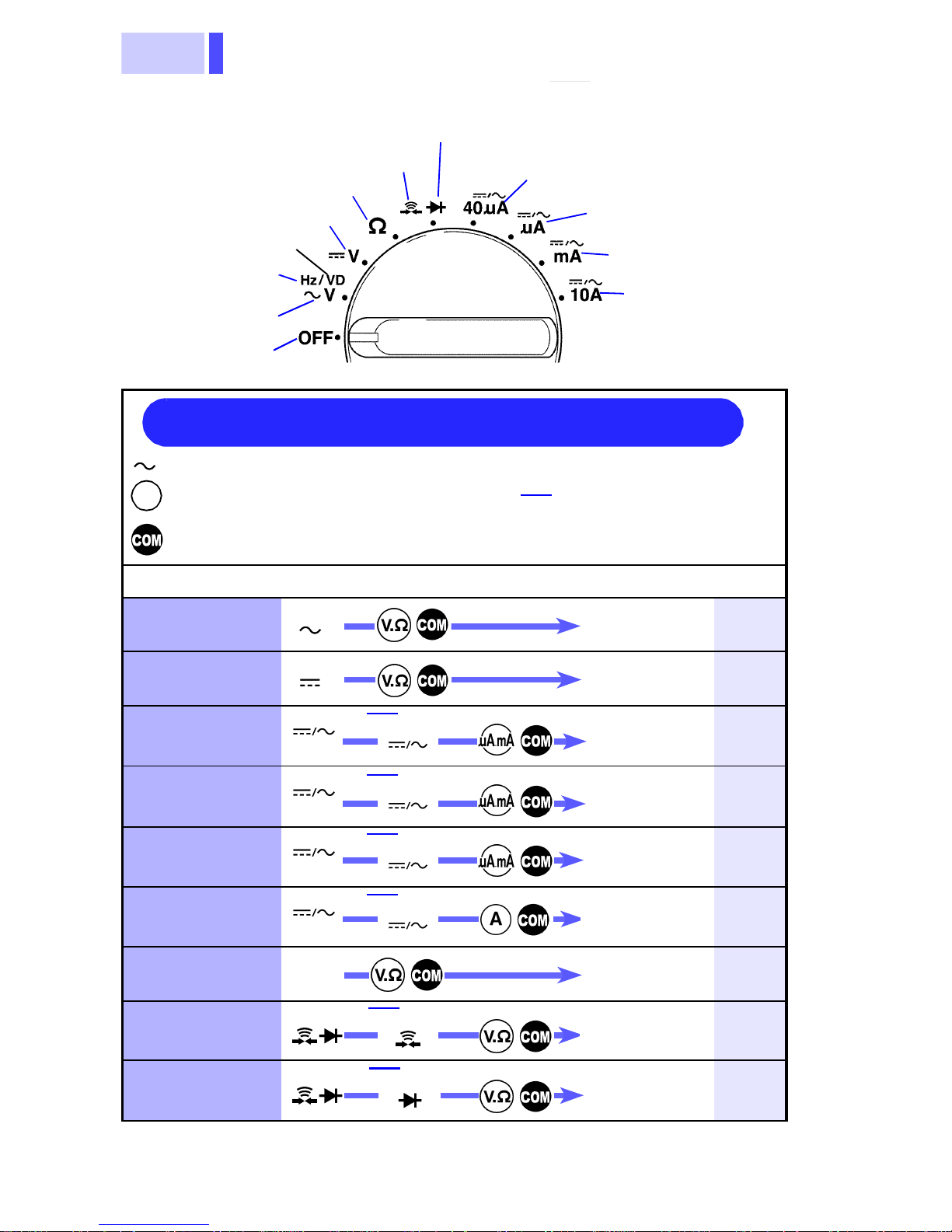
t
Function Selector
n
theses.
t
nt
( )
t
( )
t
( )
nt
10A
( )
nt
nt
(
)
nt
( )
nt
(Diode Check function)
Continuity function
Resistance function
DC voltage function
(Voltage detecting)
(Frequency
function)
AC voltage
function
Power OFF
Quick Reference
Indicates the function selector position
V
Indicates the terminal to which the red
test lead should be connected
Indicates the terminal to which the
black test lead should be conn ecte d
Press
REC•MEMO
when the
function in parentheses is being
used.
μA DC/AC current
40
function
μA DC/AC current
function
mA DC/AC curren
function
10A DC/AC
current function
Example
Switches betwee
REC•MEMO
( )
measurement to
display in paren-
Measurements Operations (page)
AC voltage
DC voltage
DC/AC Current
(40 μA)
DC/AC Current
(400/4000 μA)
DC/AC Current
(40/400 mA)
DC/AC Current
(10A)
Resistance
Continuity
V
V
40μA
μ
A
mA
Ω
REC•MEMO
REC•MEMO
REC•MEMO
REC•MEMO
REC•MEMO
Measuremen
Measureme
Measuremen
Measuremen
Measureme
Measureme
Measureme
Measureme
16
16
20
20
21
21
22
23
Diode
REC•MEMO
Measureme
24
13
1.3 Parts Names and Functions
V
e-
V
Bring test leads
c
r
line.
).
Example
V/ V/Ω/
4
10A
V/ V/Hz/Ω/
A/mA/10A
L
/
A/mA/10A
4
1
D
r
Frequency
Voltage
detecting
REC•MEMO
"Hz"
lights up
REC•MEMO
"1"
lights up
RANGE
( 1 - 4 )
×
2
RANGE
( 1 - 4 )
Measur
ment
lose to the powe
18
31
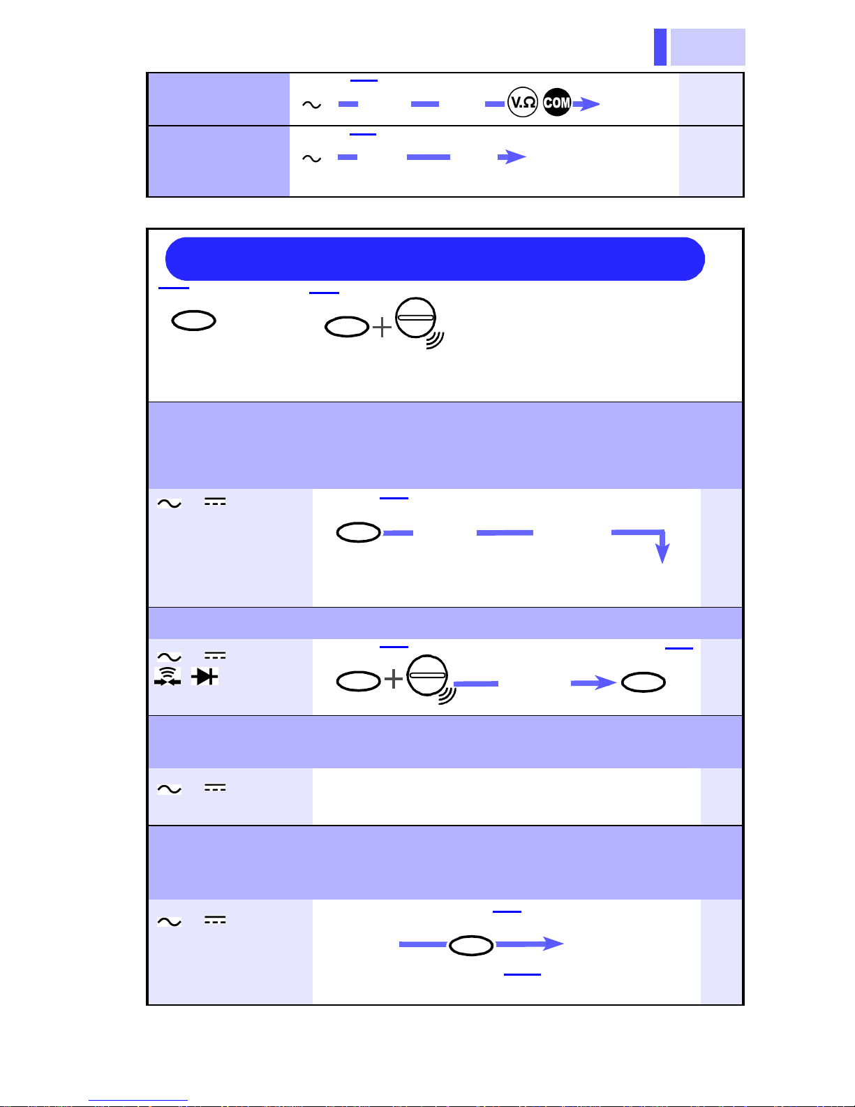
Quick Reference (application)
REC•MEMO
:Button
<1 second:
Press the button for at least 1 second.
Hold the measured value. (HOLD AUTO function)
This function is used when the displayed value cannot be checked during
measurement (such as when necessary to measure the conductor in a
dark place or using both hands.
REC•MEMO
: Turn on the power while pressing
the button (hold the button down
until a beeping sound is generated
0μA/μA/mA/
H.AUTO/REL
"HOLD"
Blinking
Move th e test lead s away from
the measurement object.
(Intermittent
sound)
25
Hold the measured value. (HOLD function)
//40μA/
H.AUTO/REL
Measure-
ment
H.AUTO/RE
26
μ
"O.F" is displayed to provide a warning
(Overflow Warning function)
V/ V/40μA
μ
When the measured value exceeds the maximum value, "O.F" is displayed.
27
Use this function to check any disc repancy f rom t he r eference,
or to control the resistance for the purpose of zero adjustment
(Relative function)
V/ V/Ω/
0μA/μA/mA/
0A
isplay the
eference.
Cancellation: H.AUTO/REL (press again)
H.AUTO/REL
(<1 second)
("REL"
lights up)
28
 Loading...