

Page 1

INSTRUCTION MANUAL
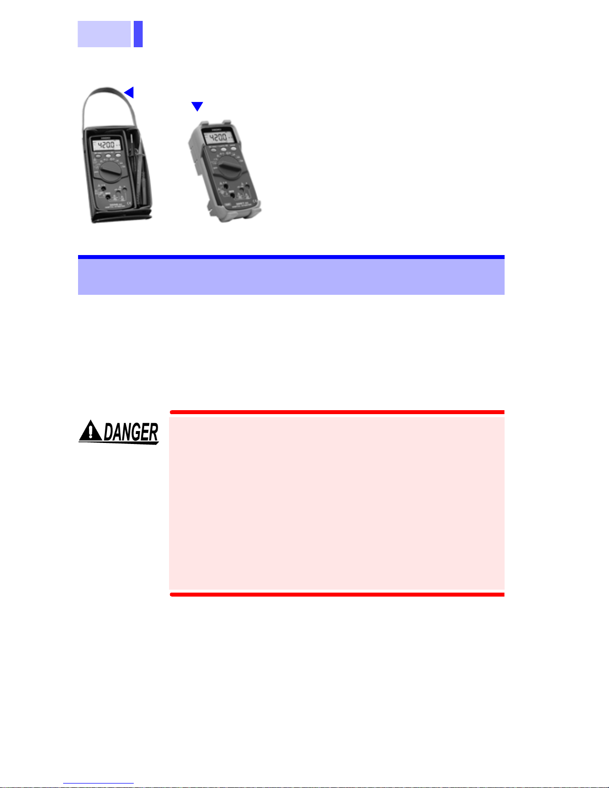
3256-50
3256-51
DIGITAL HiTESTER
Page 2

Page 3

i
Contents
Introduction .............................................................1
Inspection ............................................................... 1
Safety Notes ...........................................................2
Usage Notes........................................................... 6
Chapter 1 Overview 9
1.1 Product Overv iew ........................... ...... ..9
1.2 Features ..................................................9
1.3 Parts Names and Functions .................10
Chapter 2 Measurement Procedures 15
2.1 Voltage Meas urem en t........................... 16
2.2 Frequency Measurement...................... 18
2.3 Current Measurement........................... 19
2.4 Resistance Measurement..................... 22
2.5 Continuity Chec k............. ...... ...... .......... 23
2.6 Diode Check......................................... 24
Chapter 3 Additional Functions 25
3.1 HOLD AUTO Function ..........................25
3.2 HOLD Function .............. ...... .................26
3.3 Overflow Warning Function ..................27
3.4 Relative Display Function .....................28
3.5 Auto Power Save Function ................... 30
3.6 Voltage Detecti ng Func ti on ...................31
3.7 Dynamic Recording Function ................32
3.8 Memory Function ..................................33
Page 4

ii
Chapter 4 Specificatio ns 35
4.1 General Specifications ..........................35
4.2 Accuracy ................................................39
Chapter 5 Maintena ce and Service 43
5.1 Replacing the Batteries and Fuses ........43
5.2 Cleaning ................................................45
5.3 Service ..................................................45
Page 5

1
Introduction
Thank you for purchasing the HIOKI "3256-50/51
DIGITAL HiTESTER". To obtain maximum performance from the product, please read th is manual
first, and keep it handy for future reference.
Inspection
• When you receive the product, inspect it carefully
to ensure that no damage occurred during shipping. In particular, check the accessories, panel
switches, and connectors. If damage is evident, or
if it fails to operate according to the specifications,
contact your dealer or Hioki representative.
• Before using the product the first time, verify that it
operates normally to ensure that the no damage
occurred during storage or shipping. If you find any
damage, contact your dealer or Hioki representative.
• Before using the product, make sure that the insulation on the test leads is undamaged and that no
bare conductors are improperly exposed. Using
the product under such conditions could result in
electrocution. Replace the test leads and probes
with the specified Hioki Model 9207-10.
Page 6
2
Accessories
3256-50
*1
3256-51
Safety Notes
This manual contains information and warnings
essential for safe operation of the product and for
maintaining it in safe operating condition. Before
using the product, be sure to carefully read the following safety notes.
9207-10 TEST LEAD .................. 1
*2
Instruction Manual....................... 1
R03 Manganese battery..............2
(Supplied with this product, for
monitor)
9378 CARRYING CASE
(3256-50 only)
Protective holster
*2
(3256-51only)
*1
This product is designed to conform to IEC
61010 Safety Standards, and has been thoroughly tested for safety prior to shipment.
However, mishandling during use could
result in injury or death, as well as damage to
the product. Be certain that you understand
the instructions and precautions in the manual before use. We disclaim any responsibility for accidents or injuries not resulting
directly from product defects.
Page 7
3
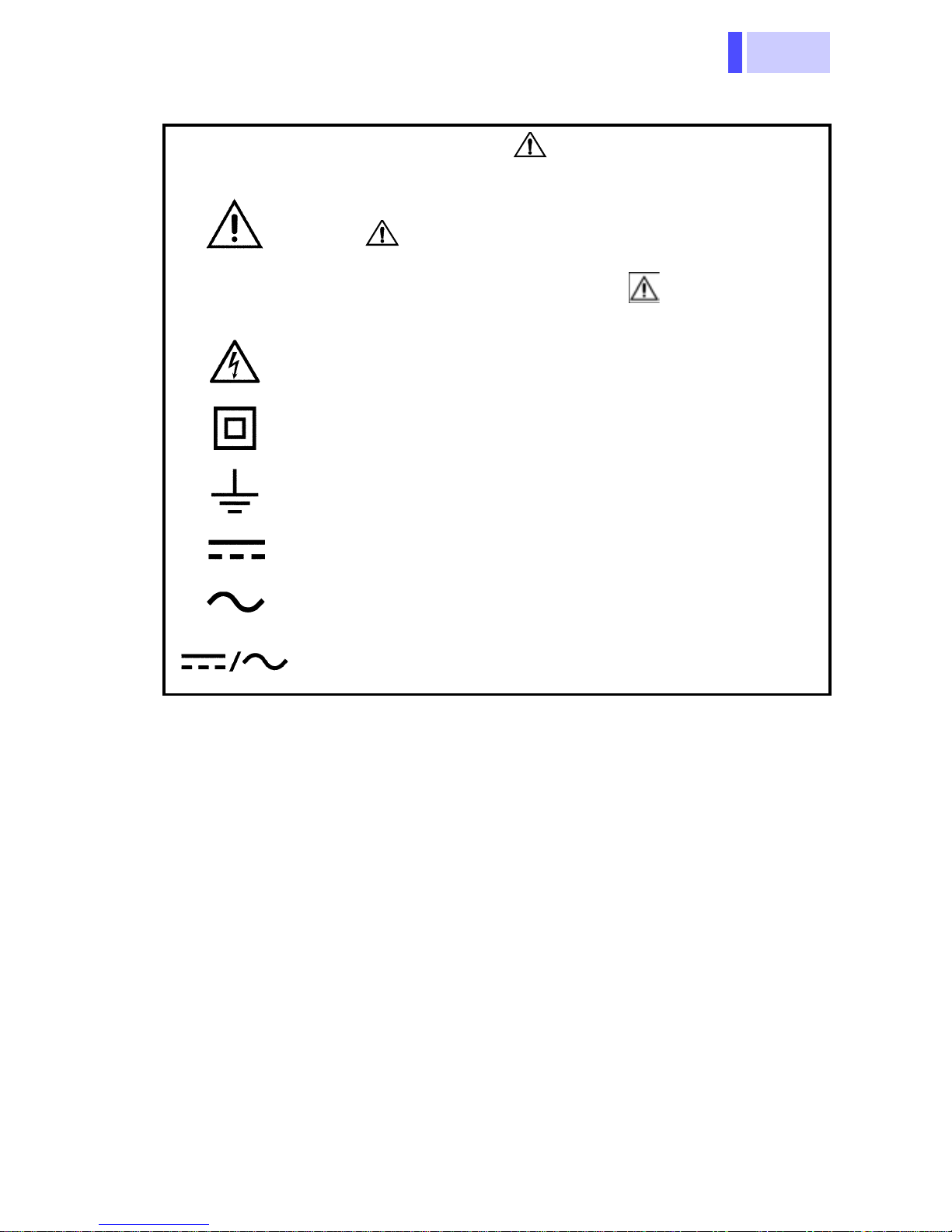
Safety Symbols
In the manual, the symbol indicates particularly important information that the user should
read before using the product.
The symbol printed on the product indicates
that the user should refer to a corresponding topic
in the manual (marked with the symbol) before
using the relevant function.
Indicates that dangerous voltage may be present
at this terminal.
Indicates a double-insulated device.
Indicates a grounding terminal.
Indicates DC (Direct Current).
Indicates AC (Alternating Current).
Indicates DC (Direct Current) or AC (Alternating
Current).
Page 8
4
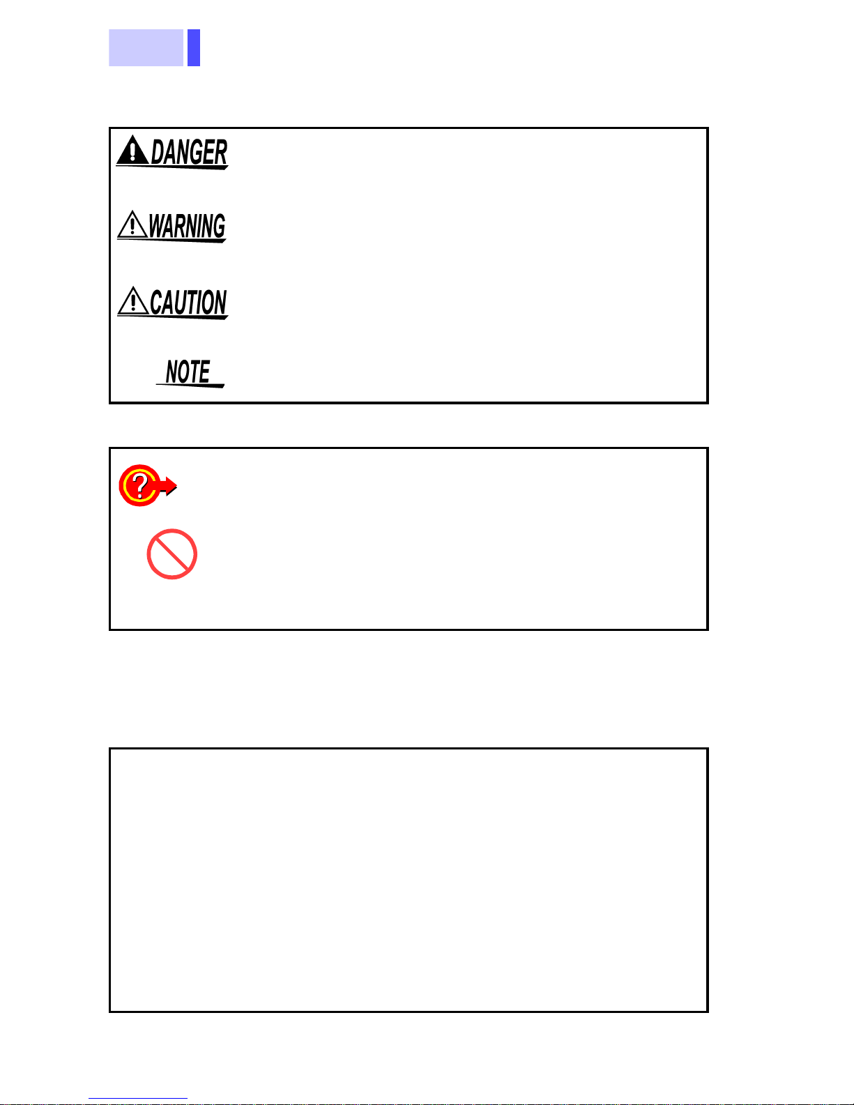
The following symbols in this manual indicate the
relative importance of cautions and warnings.
Indicates that incorrect operation presents an extreme hazard that could result in serious injury or
death to the user.
Indicates that incorrect operation presents a significant hazard that could result in serious injury or
death to the user.
Indicates that incorrect operation presents a possibility of injury to t he user or damage to the product.
Advisory items related to performance or correct
operation of the product.
Other Symbols
❖
Accuracy
f.s.
rdg.
Indicates the quick guide for operations
Indicates the prohibited action
Indicates the reference
We define measurement tolerances in terms of f.s.
(full scale), rdg. (reading) and dgt. (digit) values,
with the following meanings:
(maximum display value or scale length)
The maximum displayable value or the full length
of the scale. This is usually the maximum value of
the currently selected range.
(reading or displayed value)
The value currently being measured and indicated
on the measuring product.
(resolution)
dgt.
The smallest displayable unit on a digital measuring product, i.e., the input value that causes the
digital display to show a "1".
Page 9
5
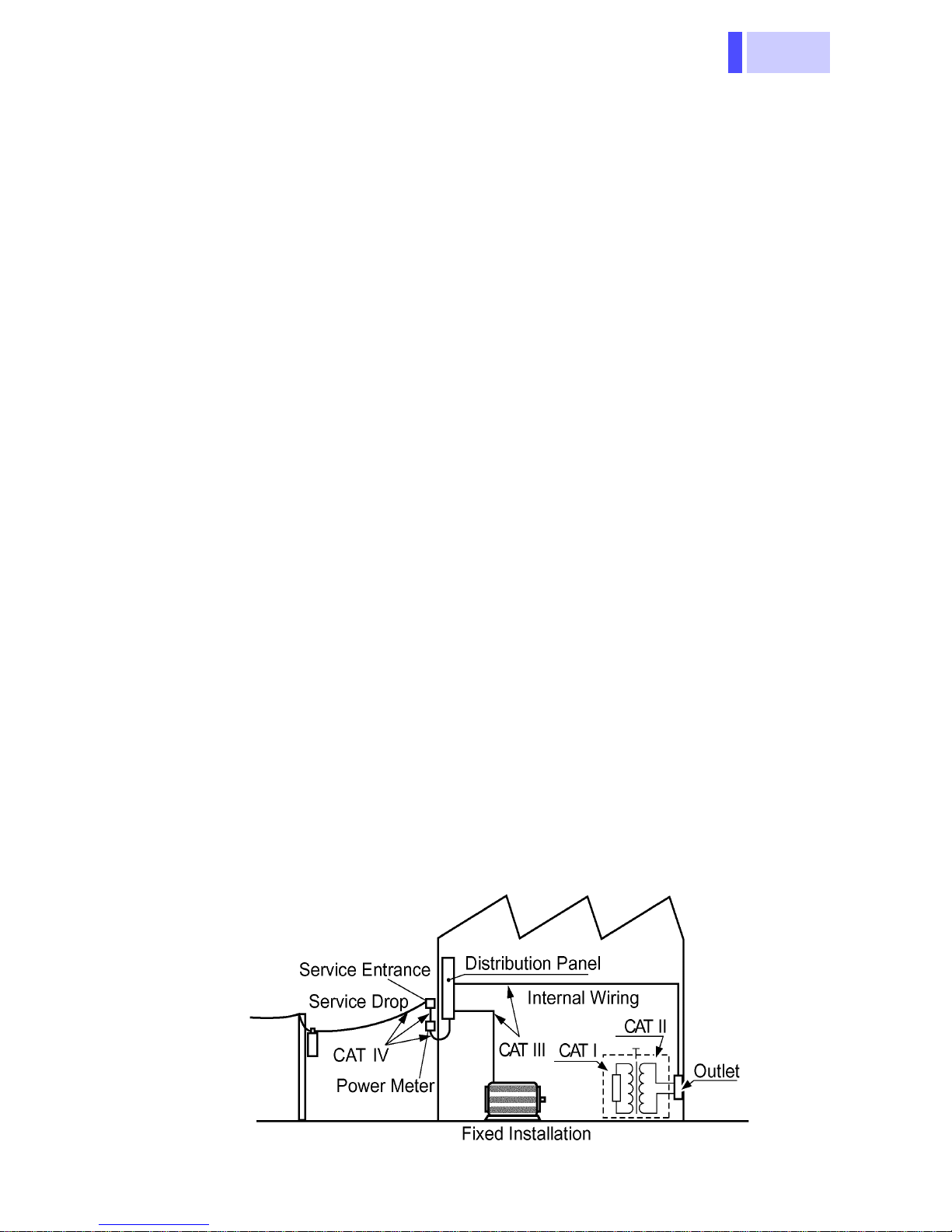
Measurement categories (Overvoltage categories)
This product complies with CATIII (600 V), CATII (1000 V) safety
requirements.
To ensure safe operation of measurement products, IEC 61010
establishes safety standards for various electrical environments,
categorized as CAT I to CAT IV, and called measurement categories. These are defined as follows.
CAT I
Secondary electrical circuits connected to an AC electrical outlet through a transformer or similar device.
Primary electrical circuits in equipment connected to
CAT II
an AC electrical outlet by a power cord (portable tools,
household appliances, etc.)
Primary electrical circuits of heavy equipment (fixed
CAT III
installations) connected directly to the distribution
panel, and feeders from the distribution panel to outlets.
The circuit from the service drop to the service en-
CAT IV
trance, and to the power meter and primary overcurrent protection device (distribution panel).
Higher-numbered categories correspond to electrical environments with greater momentary energy. So a measurement
device designed for CAT III environments can endure greater
momentary energy than a device designed for CAT II.
Using a measurement product in an environment designated
with a higher-numbered category than that for which the product
is rated could result in a sev ere accident, and mus t be carefully
avoided.
Never use a CAT I measuring product in CAT II, III, or IV environments.
The measurement categories comply with the Overvoltage Categories of the IEC60664 Standards.
Page 10
6
Usage Notes
Follow these precautions to ensure safe operation
and to obtain the full benefits of the various functions.
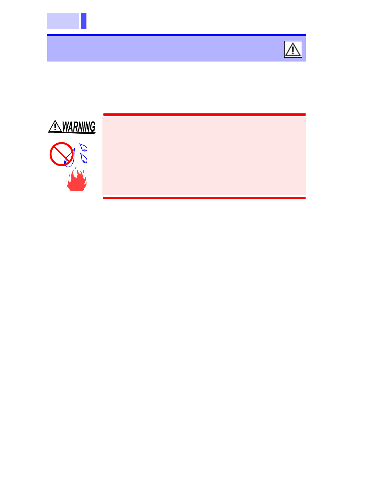
• To avoid electric shock, do not allow the
product to get wet, and do not use it when
your hands are wet.
• Do not use the product where it may be
exposed to corrosive or combustible
gases. The product may be damaged or
cause an explosion.
Page 11
7
Direct
-
st
-
n
n
sunlight
High temper
ature, high
humidity, du
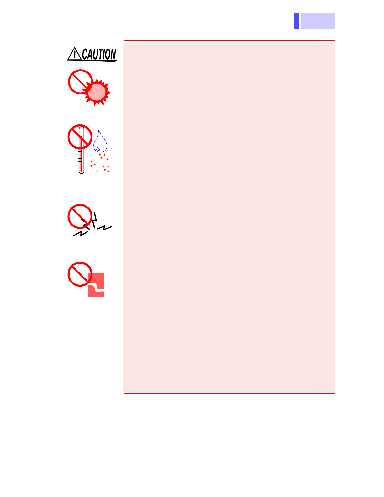
Observe the following to avoid damage to the
product.
• Installation and Operating Environment
Between 0°C and 40°C; 80% RH or less;
indoors only. Howev er, it can be safely operated
at as low as -10°C.
• Do not store or use the product where it could
be exposed to direct sunlight, high tem perature
or humidity, or condensation. Under suc h conditions, the product may be damaged and insulation may deteriorate so that it no longer meets
specifications.
• This product is not designed to be entirely
water- or dust-proof. To avoid damage, do not
use it in a wet or dusty environment.
• Do not use the product near a device that generates a strong electromagnetic field or electro-
Electromag
etic radiatio
static charge, as these may cause erroneous
measurements.
• To avoid damage to the product, protect it from
vibration or shock during transport and handling,
and be especially careful to avoid dropping.
• Adjustments and repairs should be made only
Impact,
dropping
by technically qualified personnel.
• If the protective functions of the product are
damaged, either remove it from service or mark
it clearly so that others do not use it inadvertently.
• To avoid corrosion from battery leakage, remove
the batteries from the product if it is to be st ored
for a long time.
Page 12

8
• Accurate measurement may be impossible in the
presence of strong magnetic fields, such as near
transformers and high-current conductors, or in
the presence of strong electromagnetic fields
such as near radio transmitters.
• To avoid battery depletion, turn the function
selector OFF after use (the Auto Power Save
feature consumes a small amount of current).
• The indicator appears when battery voltage
becomes low. Replace the batteries as soon as
possible.
Page 13

9
1.1 Product Ov e r view
Overview Chapter 1
1.1 Product Overview
This measurement product is a multi-functional
digital multimeter capable of measuring DC and
AC voltages, DC and AC currents, and the resistance, checking the diode and continuity, and
detecting voltage.
1.2 Features
Compliance with CE marking requirements
The measurement product is designed to comply
with the international safety standard (IEC61010-
1) and EMC standards.
Safety-designed handy digital multimeter
The measurement product is equipped with testlead misinsertion preventive shutters and fast -acting fuses at the current measurement terminals.
Multi-functional and voltage detecting
• Live conductors can be examined safely and easily.
• The Hold Auto function allows measur ed v alue s to
be maintained by simply disconnecting the test
leads.
• The Hold function maintains the displayed value.
• The Memory function saves the held value displayed.
• The Recording function displays the maximum,
minimum, average, and currently measured values
selectively.
• The Relative function displays any discrepancy
from the reference.
Page 14
1.3 Parts Names and Functions
10
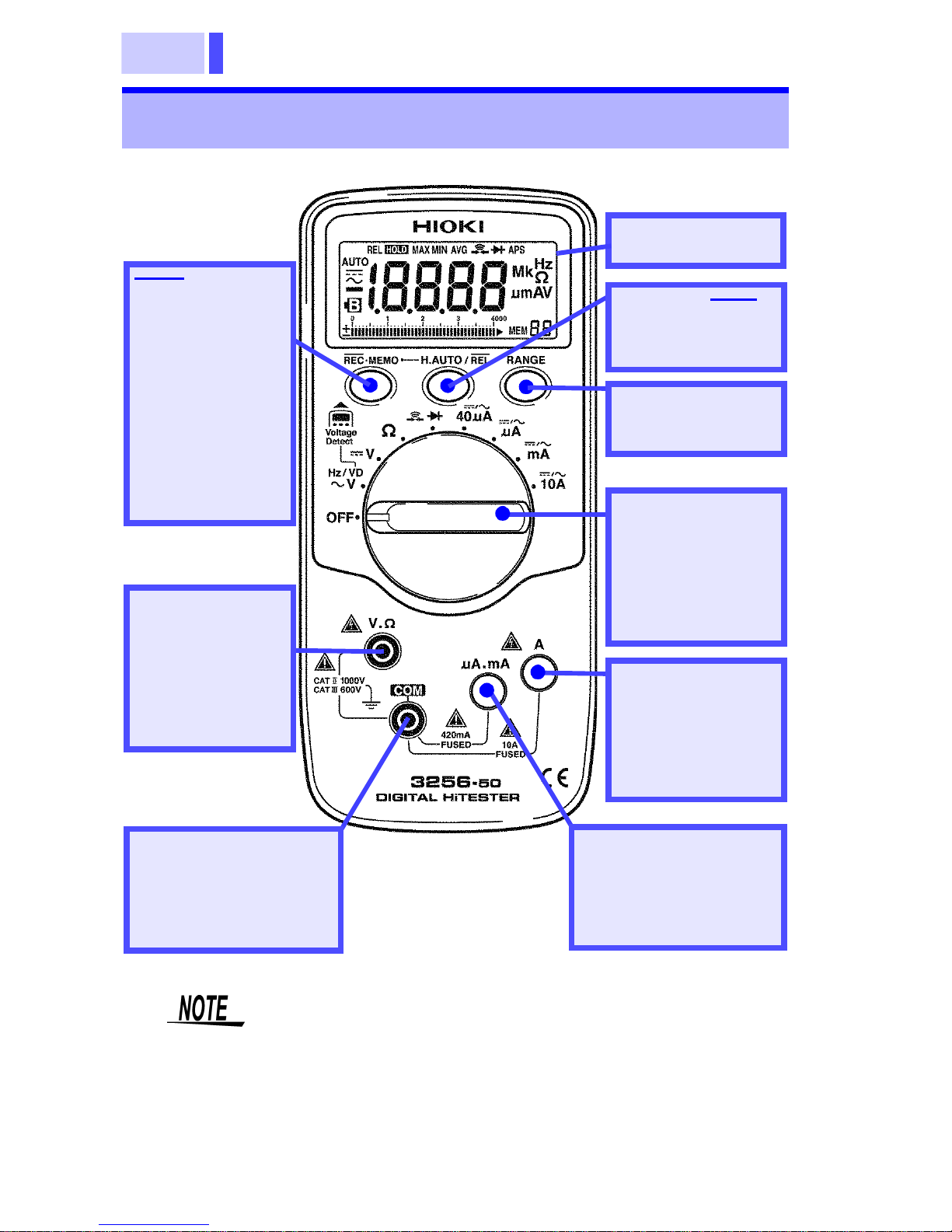
1.3 Parts Names and Functions
*: for details, see
the following
pages
REC•MEMO
Button
(Press this button
to change to the
function indi ca ted in blue.)
For other functions, see the following pages.
LCD display *
H.AUTO/REL
Button *
RANGE
Button *
V.Ω terminal
Terminal used to
measure volta ges and resistances
(red test lead)
COM terminal
Terminal com mon to
all functions
(black test lead)
The terminal shutter works together with the
function selector to prevent incorrect operation.
Note that if the function selector is toggled with
the test leads connected, the measurement
product may be damaged.
Function
Selector
(Selects functions
and turns the
power on/off)
A terminal
Terminal used to
measure currents
in 10-A mode
μA.mA terminal
Terminal used to
measure currents in
μA/mA mode
Page 15
11
1.3 Parts Names and Functions
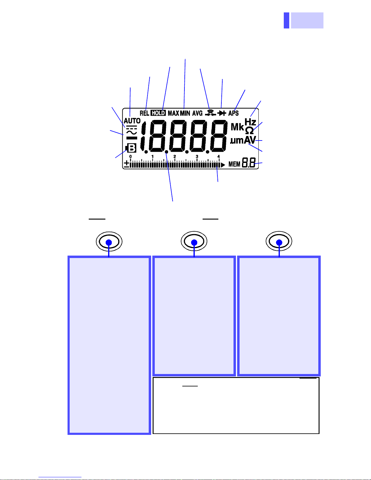
LCD(Display)
n
n
r
d
s
k
s
-
)
)
-
Indicates HOLD AUTO/
HOLD function
Indicates Relative functio n
Indicates Autorang ing
function
Indicates DC
voltage/current function
Indicates AC
voltage/current function
Indicates low
battery voltage
Lights up when the voltage
drops below the battery
accuracy guarantee voltage
(2.2±0.1 V)
REC•MEMO
Decimal point
Indicates Recording function
Indicates Continuity Check functio
Indicates Diode Check functio
Indicates Auto Powe
Save is enabl e
Frequency unit
Resistance and
continuity chec
units
Voltage and di
ode check unit
Current unit s
Indicates the
memory data
number
Bar-graph scale (42 dots)
Bar graph (with polarity indicator)
H.AUTO/REL RANGE
Changes to the function indicated in blue
Toggles between AC
and DC modes(Current measurement)
(page 19)
Recording function
(Displays MAX/MIN/
AVG)*1
(page 32)
Voltage Detecting
(page 31)
Memory Function
(page 33)
Cancels the Auto
Power Save function
*2
(page 30)
HOLD AUTO function
(Holds the measured
value)
(page 25)
Turns the HOLD
function on/off
Turns the Relative
function (displaying
the relative value) on/
off*1
*1: Press the button for at least 1 second (REC
and REL require the button to be pressed
for a longer time).
*2: Turn on the power while pressing the but-
ton, and hold the button down until a beep
ing sound is generated (power-on option).
*2
(page 26)
(page 28)
Changes the manual
range and selects
range
Changes the auto
range from the manu
al range*1
Changes the input
level
(Frequency fun cti on )
Calls data from mem
ory*2
(page 18
(page 34
Page 16
1.3 Parts Names and Functions
12
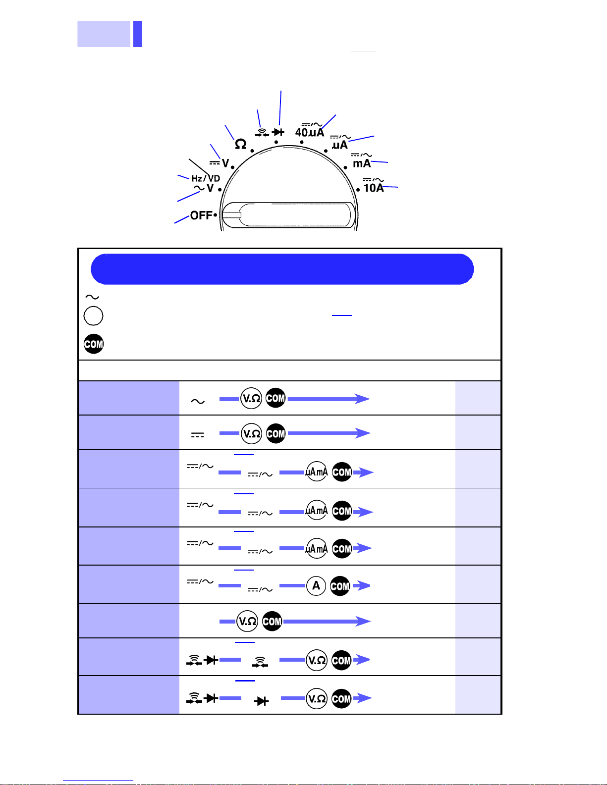
t
Function Selector
n
theses.
t
nt
( )
t
( )
t
( )
nt
10A
( )
nt
nt
(
)
nt
( )
nt
(Diode Check function)
Continuity function
Resistance function
DC voltage function
(Voltage detecting)
(Frequency
function)
AC voltage
function
Power OFF
Quick Reference
Indicates the function selector position
V
Indicates the terminal to which the red
test lead should be connected
Indicates the terminal to which the
black test lead should be conn ecte d
Press
REC•MEMO
when the
function in parentheses is being
used.
μA DC/AC current
40
function
μA DC/AC current
function
mA DC/AC curren
function
10A DC/AC
current function
Example
Switches betwee
REC•MEMO
( )
measurement to
display in paren-
Measurements Operations (page)
AC voltage
DC voltage
DC/AC Current
(40 μA)
DC/AC Current
(400/4000 μA)
DC/AC Current
(40/400 mA)
DC/AC Current
(10A)
Resistance
Continuity
V
V
40μA
μ
A
mA
Ω
REC•MEMO
REC•MEMO
REC•MEMO
REC•MEMO
REC•MEMO
Measuremen
Measureme
Measuremen
Measuremen
Measureme
Measureme
Measureme
Measureme
16
16
20
20
21
21
22
23
Diode
REC•MEMO
Measureme
24
Page 17
13
1.3 Parts Names and Functions
V
e-
V
Bring test leads
c
r
line.
).
Example
V/ V/Ω/
4
10A
V/ V/Hz/Ω/
A/mA/10A
L
/
A/mA/10A
4
1
D
r
Frequency
Voltage
detecting
REC•MEMO
"Hz"
lights up
REC•MEMO
"1"
lights up
RANGE
( 1 - 4 )
×
2
RANGE
( 1 - 4 )
Measur
ment
lose to the powe
18
31
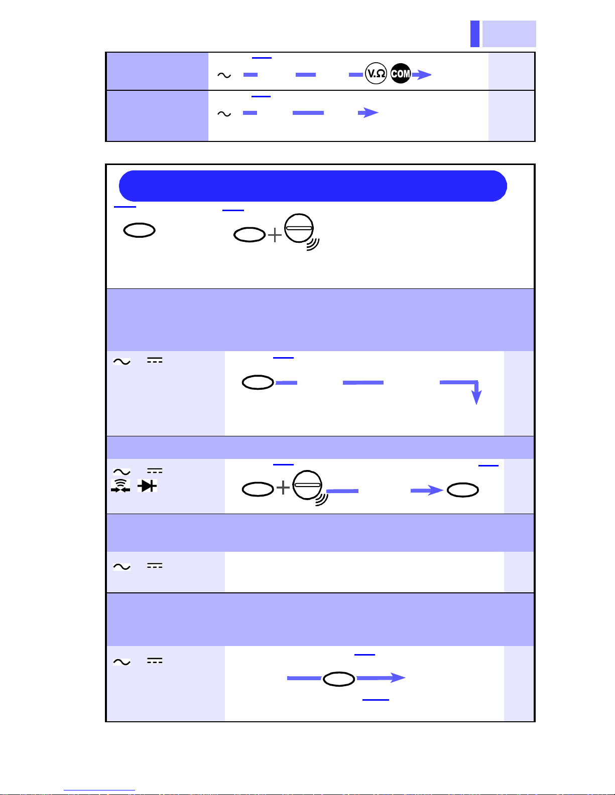
Quick Reference (application)
REC•MEMO
:Button
<1 second:
Press the button for at least 1 second.
Hold the measured value. (HOLD AUTO function)
This function is used when the displayed value cannot be checked during
measurement (such as when necessary to measure the conductor in a
dark place or using both hands.
REC•MEMO
: Turn on the power while pressing
the button (hold the button down
until a beeping sound is generated
0μA/μA/mA/
H.AUTO/REL
"HOLD"
Blinking
Move th e test lead s away from
the measurement object.
(Intermittent
sound)
25
Hold the measured value. (HOLD function)
//40μA/
H.AUTO/REL
Measure-
ment
H.AUTO/RE
26
μ
"O.F" is displayed to provide a warning
(Overflow Warning function)
V/ V/40μA
μ
When the measured value exceeds the maximum value, "O.F" is displayed.
27
Use this function to check any disc repancy f rom t he r eference,
or to control the resistance for the purpose of zero adjustment
(Relative function)
V/ V/Ω/
0μA/μA/mA/
0A
isplay the
eference.
Cancellation: H.AUTO/REL (press again)
H.AUTO/REL
(<1 second)
("REL"
lights up)
28
Page 18

1.3 Parts Names and Functions
14
V
4
10A
.
("APS"
Power
4
1
R
(
L
)
4
1
)
4
1
.
E
4
10A
Cancel the Auto-Power Save function.
(Auto-Power Save function)
V/ V/Hz/
D/Ω///
0μA/μA/mA/
REC•MEMO
Enable the Power Save function:
OFF
Function
change
Press this button unt il a
beeping sound is generated
lights up)
10 minutes
After
Save
mode
30
Check the maximum, minimum, and average values during
measurement. (Recording function)
V/ V/Ω/
0μA/μA/mA/
0A
EC•MEMO
<1 second)
MAX:maximum value/ MIN:minimum value/
AVG:average value / MAX MIN AVG: Current
value
Cancellation: REC
("
MAX MIN A VG"
lights up
•MEMO (press aga in)
)
H.AUTO/R E
(
MAX MIN AVG
32
Save the measured value to memory. (Memory function)
V/ V/Ω/
0μA/μA/mA/
0A
Hold the displayed value
H.AUTO/REL
REC •MEMO
("MEM."
lights up
33
Call the saved data.
V/ V/Ω/
RANGE
0μA/μA/mA/
0A
Delete all data from memory.
V/ V/Ω/
RANGE
0μA/μA/mA/
Memory-data
V
REC•MEMO
V
display
Select MEM#
(<1 second)
RANG
34
RANGE
34
Page 19

15
1.3 Parts Names and Functions
Measurement
Procedures
Observe the following precautions to avoid
electric shock.
• Always verify the appropriate setting of the
function selector before connecting the
test leads.
• Disconnect the test leads from the measurement object before switching the function selector.
• When it is necessary to replace the measurement terminal, remove the test lead
from the measurement object and disconnect the lead from the terminal before toggling the function selector.
Chapter 2
Even when the shutter is closed, the terminals are not sufficiently separated. To avoid
electrocution, do not touch the terminals.
When the shutter is damaged, discontinue measurement and repair it.
Page 20

2.1 Voltage Measurement
16
n
V
r
r
r
t
,
d
2.1 Voltage Measurement
• The maximum input voltage is 1000 VDC,
7
1000 Vrms, or 10
However, for CATIII circuits, the maximum
voltage is 600 Vrms. Attempting to measure voltage in excess of the maximum
input could destroy the product and result
in personal injury or death.
• To avoid electrical shock, be careful to
avoid shorting live lines with the test leads.
• For safety, test lead connections must
always be made at the secondary side of a
V•Hz.
AC Voltage
Measurement
circuit breaker.
• The maximum rated voltage between input
terminals and ground is 1000 V DC/AC
7
(CATII), 600 V DC/AC(CATIII), or 10
V•Hz.
Attempting to measure voltages exceeding
this limit with respect to ground could damage the product and result in personal
injury.
DC Voltage
Measurement
1. Move the functio
selector to the
position for AC mode o
to the V position fo
DC mode (in eithe
case, “V” lights up).
Red
Black
2. Connect the red tes
lead to terminal V.Ω
and the black test lea
to termina l COM.
Page 21

17
2.1 Voltage Measurement
2.
o
t,
d
AC Voltage Measurement
Black
Red
DC Voltage Measurement
Black
Red
3. Connect the test leads t
the measurement objec
and read the indicate
value.
Selecting the manual
range:
Reselecting the auto
range:
Holding the measured
value:
HOLD AUTO Function,
page 25) or
HOLD Function, page
26)
Appearance of O.F: The measured value exceeds 4200
Press RANGE
("AUTO" is turned off)
Press RANGE
ond) ("AUTO" lights up)
Press H.AUTO/REL
ment
Move the test leads away from the
measurement object.
Press H.AUTO/REL
Measurement
REL
counts (up to the 420-V range) or
1050 counts (1000- V ran ge ).
→ Intermittent sound →
(for at least 1 sec-
→ Measure-
+Power-on →
→ Press H.AUTO/
The indicated value may vary due to the existence
of induced voltage under no-power conditions.
However, this is not a problem.
Page 22

2.2 Frequency Measurement
18
1.
"
)
-
2.2 Frequency Measurement
• The maximum input voltage is 1000 VDC,
7
1000 Vrms, or 10
However, for CATIII circuits, the maximum
voltage is 600 Vrms. Attempting to measure voltage in excess of the maximum
input could destroy the product and result
in personal injury or death.
• For safety, test lead connections must
always be made at the secondary side of a
circuit breaker.
V•Hz.
Move the function selector to
the V position and press
the REC
lights up).
REC•MEMO
2. Connect the red test lead to
terminal V.Ω, and the black
test lead to terminal COM.
3. Select the input level (1 to 4
using the RANGE button, in
accordance with the input volt
age.
4. Connect the test leads to the
measurement object, and read
RANGE
Input level
Attenuation factor of the input voltage
(1/10n)
(n: Scale num be r)
Indication range: 0.5 Hz to 500 kHz
the indicated value.
•MEMO button ("Hz
Input level Range
1
0.8 to 4 V
2
4 to 40
3
40 to 400 V
4
400 to 1000V
4.200V
42.00V
420.0V
1000V
Canceling the frequency
measurement:
Press REC•MEMO
Page 23

19
2.3 Current Measurement
2.3 Current Measurement
• Never apply voltage to the test leads when
a current measurement function is
selected. Doing so may damage the product and result in personal injury.
• To avoid electrical accidents, remove
power from the circuit before connecting
the test leads.
• To avoid electrical shock, do not use the
product to measure current in circuits of
600 V or greater. The current function
overload protection trips at 600 Vrms.
• Maximum input current in each range
40μA/μA/mA range: 420mADC/ 420 mA rms
10A range: 10 ADC/ 10 A rms
Do not input a current in excess of this
value. Otherwise, the measurement product will be damaged, resulting in an accident that may cause injury or deat h.
Select ing t he man ual ra nge:
Reselecting the auto range:
Holding the measured
value:
HOLD AUTO Function,
page 25) or
Press RANGE
("AUTO" is turned off)
Press RANGE (for at least 1 second) ("AUTO" lights up)
Press H.AUTO/REL
ment → Intermittent sound →
Move the test leads away from the
measurement object.
→ Measure-
HOLD Function, page 26)
Appearance of O.F: The measured value exceeds
Press H.AUTO/REL
Measurement →
Press H.AUTO/REL
1050 counts(10-A range) or 4200
counts (other range s).
+Power-on →
Page 24

2.3 Current Measurement
20
1.
e
g
r-
st
e
d
t
e
g
r-
t
e
d
40μA Measurement (42μA range)
Move the function se lector to th
40μA position.
REC•MEMO
2. Select DC ( ) or AC ( ) usin
the REC•MEMO button.
3. Connect the red test lead to te
minal μA.mA, and the black te
lead to terminal COM.
4. Connect the test leads to th
Black
μA
Red
Measurement
1. Move the function selector to th
REC•M EMO
2. Select DC ( ) or AC ( ) usin
3. Connect the red test lead to te
measurement object, and rea
the indicated value.
The Auto Range function is no
provided.
(420 μA/4200 μA
μA position.
the REC•MEMO button.
minal μA.mA, and the black tes
lead to terminal COM.
range
)
Black
Red
4. Connect the test leads to th
measurement object, and rea
the indicated value.
Page 25

21
2.3 Current Measurement
1.
e
g
t
e
d
1.
e
g
io
-
e
t
mA
Black
Measurement (40 mA/400 mA)
Move the function selector to th
mA position.
REC•MEMO
2. Select DC ( ) or AC ( ) usin
the REC•MEMO but ton.
3. Connect the red test lead to ter
minal μA.mA, and the black tes
lead to terminal COM.
4. Connect the test leads to th
Red
measurement object, and rea
the indicated value.
A
Measureme nt
Note that the product may be damaged if current
exceeding the selected measurement range is
applied for a long time (for the 10 A range, continuous current m ust be limited to 7A, or to less than
one minute if over 7A)
REC•MEMO
Black
Red
(10 A range)
Move the function selector to th
10A position.
2. Select DC ( ) or AC ( ) usin
the REC•MEMO button.
3. Connect the red test lead to term
nal A, and the black test lead t
terminal COM.
4. Connect the test leads to the mea
surement object, and read th
indicated value.
The Auto Range function is no
provided.
Page 26

2.4 Resistance Measurement
22
e
r-
d
e
d
2.4 Resistance Measurement
• Never apply voltage to test leads when
the Resistance function is selected.
Doing so may damage the product and
result in personal injury.
• To avoid electrical accidents, remove
power from t he circuit before measur ing.
1. Move the function selector to th
Ω position.
Red
Black
Black
2. Connect the red test lead to te
minal V.Ω, and the black test lea
to term i n a l COM.
3. Connect the test leads to th
measurement object, and rea
the indicated value.
Red
Selecting the manual range:
Reselecting the auto range:
RANGE (AUTO is turned off)
RANGE
ond) ("AUTO" lights up)
(Pr es s for at l east 1 sec-
Holding the measur ed
value:
HOLD AUTO Function,
page 25) or
HOLD F unction, page 26)
H.AUTO/REL
→Intermittent sound→
Move the test leads away from the
measurement object.
H.AUTO/REL
surement →H.AUTO/REL
→Measurement
+Power-on→ Mea-
Page 27

23
2.5 Continuity Check
e
e
).
r-
d
e
2.5 Continuity Check
• Never apply voltage to test leads when
the Continuity function is selected. Doing
so may damag e the product and res ult in
personal injury.
• To avoid electrical accidents, remove
power from the circuit before measuring.
1. Mov e the function selector to th
position.
2. Select Diode ( ) using th
REC•MEMO
REC•MEMO
button ( lights up
Red
Black
Black
Red
3. Connect the red test lead to te
minal V.Ω, and the black test lea
to terminal COM.
4. Connect the test leads to th
measurement object.
When the continuity (threshold:
50±30 Ω or less) is established,
the beeping sounds and the
resistance is displayed
(fixed to the 420-Ω range).
Page 28

2.6 Diode Check
24
e
e
).
r-
d
e
t-
l
2.6 Diode Check
• Never apply voltage to test leads when
the Diode Check function is selected.
Doing so may damage the product and
result in personal injury.
• To avoid electrical accidents, remove
power from t he circuit before measur ing.
1. M ove the function selector to th
position.
REC•MEMO
Red
Black
Cathode Anode
2. Select Diode ( ) using th
REC•MEMO
button ( lights up
3. Connect the red test lead to te
minal V.Ω, and the black test lea
to termina l COM.
4. Connect the test leads to th
measurement object.
The display shows forward vol
age (0.4 V to 0.7 V) for a norm a
diode.
Black
Appearance of O.F: The diode is invertedly connected or
Appearance at approximately 0 V:
Red
broken.
The diode is short-circuited.
Page 29

25
Additional
)
e
ce
t o
rm
mo
ct.
est
3.1 HOLD AUTO Function
Functions
Chapter 3
3.1 HOLD AUTO Function
Functions
Description
H.AUTO/REL
HOLD
(blinks)
Measure
V/ V/Ω/40μA/μA/mA/10A
Simply moving the test leads away from the measurement object holds the measured value. This
function is useful when it is difficult to read the
displayed value in the current location or both
hands are being used to conduct the measurement.
1. Select the desired function and connect th
the measurement product.
2.
Press the H.AUTO/REL button.
("HOLD" blinks) (In the measurement of resistan
played.)
HOLD
(lights up)
Beeping
sound
HOLD
(blinks)
The measured
value is held.
Blind zone V/ V:
Ω: O.F
Canceling the hold
mode:
3. Connect the test leads to the measuremen
4. When the intermittent sound is heard,
A/ A: less than 40 counts
HOLD AUTO is disabled in the AC/DC 420-mV
range.
the measured value is stabilized, an inte
is generated.
("HOLD" lights up)
leads away from the measurement obje
sured value immediately before the t
removed is held.
("HOLD" blinks)
420 mV range, less than 400 counts (other range
Press H.AUTO/REL again.
(HOLD is turned off)
Saving the data: Press
REC•MEMO
Page 30

3.2 HOLD Function
26
g
d
g
e
d
n
e
e
3.2 HOLD Function
Functions
Description
H.AUTO/REL
H.AUTO/REL
The measured
value is held.
V/ V/Hz/Ω///40μA/μA/mA/10A
This function holds the currently measured
value.
1. Turn on the power while pressin
the H.AUTO/REL button, and hol
Measure
Displayed
value
the button down until a beepin
sound is generated (toggle th
function selector to the desire
position).
2. Press the H.AUTO/REL butto
HOLD
lights up
again at the measured value to b
held. The value is held.
("HOLD" lights up)
3. To cancel the hold mode, pres s th
H.AUTO/REL button again.
The Hold function is active until the measurement
product is turned off.
Page 31

27
3.3 Overflow War ning Function
3.3 Overflow Warning Function
Functions
Description
V/ V/40μA/μA/mA/10A
When the measured value exceeds the maximum indication (4200 counts), O.F is displayed
and an intermittent sound is generated.
When the measured value exceeds 1050 counts in
the ranges specified below, O.F is displayed and
an intermittent sound is generated.
• Maximum range (1000-V range) of DC voltage
measurement ( V) or AC voltage measurement
(V)
• 10-A range of current measurement
Example: When the measured value exceeds
1050 counts in the 1000-V range of AC voltage
measurement ( V)
Page 32

3.4 Relative Display Function
28
r
d
o
o
L
d
d
n
d
Checking any discrepancy from the reference (when 10 V is
3.4 Relative Display Function
Functions
Description
V/ V/Ω/40μA/μA/mA/10A
Once an arbitrary value is specified as a reference, the relative value ag ainst the reference is
displayed. This function is useful to check any
discrepancy from the reference.
defined as the reference in the voltage measurement)
Measure a voltage of 10 V
1. Move the function selecto
to the desired position an
connect the test leads t
the measurement product.
(example: V)
2. Connect the test leads t
The manual
range is
enabled.
The bar graph
indicates the
measured value.
H.AUTO/REL
for at least
1 second
the measurement object.
3. Press the H.AUTO/RE
button for at least 1 secon
for the value to be define
as the reference.
(Example: Press the button at
10 V. "REL" lights up and
“0000” is displayed.)
4. Measure the voltage agai
and read the displaye
value (discrepancy from
the reference).
(The measured value minus the
reference is displayed.)
Any discrepancy from the reference
(10 V) is displayed. In the case of a
negative value, “-” is also displayed.
The measurement range is fixed to the range that
is active when the
If the reference value deviates from the full scale,
O.F is displayed. While O.F is displayed, the Relative function is disabled.
H.AUTO/REL button is pressed.
Page 33

29
3.4 Relative Display Function
r
-
e
s.
st
L
c-
to
t,
d
Application: Using the Relative Display function for the purpose
o
f zero adjustment in the measurement of low resistances
Short-circuit the test leads
1. Move the function selecto
to the Ω position and con
nect the test leads to th
equipment.
2. Short-circuit the test lead
The resistance of the te
leads is displayed.
3. Press the H.AUTO/RE
H.AUTO/REL
for at least
1 second
button for at least 1 se
ond.
("REL" lights up, "0000")
4. Connect the test leads
the measurement objec
and read the indicate
value.
Measure the resistance.
Canceling the Relative
function:
Press H.AUTO/REL
Page 34

3.5 Auto Power Save Function
30
3.5 Auto Power Save Function
Functions
Description
All functions
Approximately 10 minutes after completing final
operation, the measurement product automatically enters Power Sa ve mode. When the measurement product is turned on, it automatically
enters Auto Power Save mode ("APS" lights up).
• In Power Save mode, the LCD is blank but power
is supplied to the measurement product.
• To avoid battery depletion, turn the function
selector OFF after use (the Auto Power Save
feature consumes a small amount of current).
Recovery from Power Save mode:
Turn off the function selector. In the current measurement, disconnect the test leads from the terminals and turn off the function selector.
After the measurement product exits Power Save
mode, all conditions are reset . If t he m easur ement
product is to be us ed f or an extended perio d, Aut o
Power Save mode should be canceled in advance.
Canceling the Auto Power Save function:
REC•MEMO
The Auto Power Save function is disabled until the
measurement product is turned off (APS is turned
off).
Turn on the measurement product while pressing the
REC•MEMO button.
(Hold down the button
until the beeping sound is
generated.)
Page 35

31
3.6 Voltage Detecting Function
o
s
e
t
r
e
e
r
e
n
-
3.6 Voltage Detecting Function
This function should be used for the covered
power line. Depending on the measurement status, the power may not be detected. Before using
this function, check that the measuring device can
detect the existing live power line.
Functions
Description
REC•MEMO
V
This function allows you to check whether the
power line is live. If the line is live, the measurement product indicates that fact both audibly
(intermittent sound) and visually (display).
1. Move the f unction selector t
the V position, and pres
the REC•MEMO button twic
(“1” lights up).
2. Bring the measuremen
product close to the powe
line.
3. If necessary, change th
detection range with th
RANGE button.
Guidelines for detecting power line level
1-3: Approx. 100 V
4: Approx. 200 V
RANGE
When the line is live, the ba
graph fluctuates.
When the voltage is outsid
of the detection range, a
intermittent sound is gener
ated and the display blinks.
The voltage detecting sensor is
mounted at the top of the measurement product.
Bring the top close to the
power line, as shown at left.
Page 36

3.7 Dynamic Recording Funct ion
32
1.
n
o
e
t-
e
f
:
-
-
3.7 Dynamic Recording Function
Functions
Description
REC•MEMO
Current
value
Maximum value
Minimum value
Average value
V/ V/Ω/40μA/μA/mA/10A
This function allows the maximum (MAX), minimum (MIN), average (AVG ), and currently measured values to be displayed selectively. It is
useful for measuring any discrepancy over an
extended period.
Select the desired functio
Press
for at least
1 second.
and connect the test leads t
the measurement product.
2. Connect the test leads to th
measurement object.
3. Press the
REC•MEMO
bu
ton for at least 1 second.
H.AUTO/REL
("MAX MIN AVG" lights up)
4. Select the item using th
H.AUTO/REL
• The maximum, minimum, and aver
age measured after the acti vation o
the Recor ding f unction a re au tom ati
cally recorded (recording interval
approx. 0.4 seconds).
• When the maximum and/or minimum
is updated , a beepin g sound is g en
erated.
• The simple average is displayed
within 30 min from the star t of mea
surement and t he moving ave rage is
displayed after the elapse of 30 min.
• While the Recording function is in
operation, the Auto Power Save
function is disabled (APS is turned
off). The range is fixed.
button.
Appearance of O.F: The measurement range exceeds the
Canceling Press REC
specified level.
Before using the Recording function, use
the manual range to set the range assumed as the maximum level.
•MEMO again.
Page 37

33
3.8 Memory Function
e
d
n
f
t
e
3.8 Memory Function
Saving data to memory
Functions
Description
REC•MEMO
V/ V/Ω/40μA/μA/mA/10A
This function memorizes the measured value
held using the Hold Auto or Hold function.
1. Hold the measured valu
using the Hold Auto or Hol
function.
2. Press the REC•MEMO butto
in hold mode. The value dis
played is saved in mem ory o
the number specified.
Wait a moment for curren
value display on the LCD.
Up to 20 values can b
saved.
Memory numbers cannot be specified.
The data is saved to the memory in order, starting from 01. When the memory number reaches
20, the subsequent data sets are overwritten to
memory starting from number 01.
Page 38

3.8 Memory Function
34
e
.
o
t-
s
o
r.
d
e
.
Calling data from memory
Call data from memory as specified below.
RANGE
1. Turn on the power whil
pressing the RANGE button
Move the function selector t
the V position (hold the bu
ton down until a beeping sou nd i
generated).
2. Press the RANGE button t
select the memory numbe
RANGE
When there is no data
in memory
Deleting all data from memory
The saved data is displaye
on the LCD.
Delete all data from memory as specified below.
REC•MEMO
Press both buttons
simultaneo usly for at
least 1 second.
RANGE
Data in the memory of the specified number cannot
be deleted.
Returning to the
normal measurement mode:
In Memory Call mode, press th
REC•MEMO and RANGE buttons
simultaneously for at least 1 second
All data is deleted from memory.
Toggle the function selector.
(Five minutes after completing final operation,
the measurement product returns to the normal measurem ent mo de. )
Page 39

35
4.1 General Specifications
Specifications Chapter 4
4.1 General Specifications
Measurement
Method
AC Measurement
System
Function
Additional
Function
Dual integration
Average rectifying measurement
DC voltage ( V), AC voltage( V),
Resistance (
AC current ( A), Continuity check( ),
Diode check( ), Frequency (Hz ),
Voltage detecting
Auto Range function
Manual Range function
Hold functi o n
Hold Auto function
Relative Display Function
Dynamic Recording function
Memory function (Registration, call, deletion)
Auto Power Save function
Overflow Warning function
Battery-Life Warning function
Ω), DC current ( A),
Display Type TN type LCD, 1/4 duty, dynamic drive
Display Elements 3(1/2) dgt.
Units and Symbols
Bar-graph
Indicator
Max. 4200 counts (19,999 counts for Hz
function)
Number display: "20"
Polarity indicator: "–" sign (automatic)
Overflow indicator: "OF" or "–OF"
AUTO/REL/HOLD/MAX/MIN/AVG/ / /
APS
M/k/m/μ/Hz/Ω/A/V/ / / /MEM
Indication of scale, 42-dot bar graph, and ±
(polarity)
Page 40

4.1 General Specifications
36
Input Terminals V.Ω ter m i n a l (V, Hz, Ω, continuity, diode)
μA.mA/ A/ COM terminals
Equipped with terminal shutter to prevent
improper operation.
Function Selector Rotary selector
Range Switching Auto/Manual Range
Sampling Rate 2.5 S/s (except Frequency), 5 S/s (Fre-
quency), 25 S/s (Update of bar graph)
Power Supply Two manganese (R03) batteries or
two alkaline (LR03) batteries
Rated supply voltage:1.5VDC × 2
Battery-Life
Warning
Continuous
Operating Time
Maximum Rated
Voltage to Earth
Maximum Input
Voltage
Maximum Input
Current
indicates low battery
(2.2 V±0.1V or less)
Approx. 100 hours
( V, with R03 manganese batteries)
Approx. 200 hours
( V, with LR03 alkaline batteries)
1000VDC/ 1000Vrms(sin), or 107V•Hz(CATII)
7
600VDC/ 600Vrms(sin), or 10
V•Hz(CATIII)
V/ V/Ω/Hz
1000VDC/ 1000Vrms(sin), or 107V•Hz(CATII)
600VDC/ 600Vrms(sin), or 10
7
V•Hz(CATIII)
A/ A
42μA - 420mA range: 420 mA DC/AC
(fuse 0.5A/700V DC/AC)
10A range:10 A DC/AC
(fuse 10A/600V DC/AC)
Dielectric Strength Input terminals to case:
Noise Suppression
Maximum Rated
Power
7.4 kVrms sin (50/60 Hz for one minute)
NMRR: V -60dB or better (50/60 Hz)
CMRR: V -100dB or better (50/60 Hz)
V -60dB or better (50/60 Hz)
20 mVA (supply voltage 3.0 V)
0.1 mVA (Auto Power Saving,
supply voltage 3.0 V)
Page 41

37
4.1 General Specifications
Operating
Indoors, altitude up to 2000 m (6562-ft.)
Environment
Operating Tem per-
ature & Humidity
Storage Tempera-
ture & Humidity
Tem peratur e
Characteristic
0 to 50°C (32 to 122°F), at 80%RH or less
(non-condensating)
-20 to 60°C (-4 to 140°F), at 70%RH or
less (non-condensating)
(Measurement accuracy) × 0.1/°C
(except 23±5°C)
Size & Weight Approx.76W × 167H × 33D mm
(2.99"W × 6.57"H × 1.30"D)
without protrusions
(
)
Approx. 260 g (9.2 oz)
Accessories 9207-10 TEST LEAD
Instruction Manual
Two R03 manganese batteries
Protective holster(3256-51) or
9378 CARRYING CASE (3256-50)
Applicable
Standards
Safety EN61010-1:2001
EN61010-031:2002
Pollution Degree 2
Measurement Category III(600 V),
Measurement CategoryII(1000 V)
(Anticipated Transient Overvoltage: 6000 V)
EMC EN61326:1997+A1:1998+A2:2001
+A3:2003
Options 9207-10 TEST LEAD
9014 HIGH VOLT AGE PROBE*(30 kVDC)
(*no CE marking)
3853 CARRY ING CASE (for 3256-51 can
be packag ed together with the holster.)
9378 CARRYING CASE (St andard item for
the 3256-50)
Page 42

4.1 General Specifications
38
Protective Fuse 10A terminal: TDC600-10A
(made by Cooper Bussmann*)
Rating 10 A/600 VAC Fast-Acting
Breaking capacity: 10 kA/250 VAC,
200 A/600 VAC
μAmA terminal:70125 (made by SIBA Inc.)
Rating 0.5 A/700 VAC Fast-Acting
Breaking capacity: 50 kA
Cooper Industries Inc., Bussmann Division,
*
USA
Page 43

39
4.2 Accuracy
4.2 Accuracy
Accuracy guarantee for
23±5°C(73±9°F), 80%RH or less
temperature and humidity
Guaranteed accuracy
1 year
period
Regulated power supply range
3.4 V or lower (until the mark
lights up)
(rdg.: displayed value, dgt.: resolution)
Voltage Measurement
V
Range
[V]
420.0 m
4.200
42.00
420.0
1000
Accuracy
±(rdg.)±(dgt.)
±0.5%±2
±0.5%±2
±0.5%±2
±0.5%±2
±0.5%±2
100 MΩ or more
Approx. 11MΩ
Approx. 10MΩ
Approx. 10MΩ
Approx. 10MΩ
Input Impedance
(Frequency range)
*1
V
420.0 m
4.200
42.00
420.0
1000
±1.5%±3
±1.2%±3
±1.2%±3
±1.2%±3
±1.2%±6
*2
100MΩ or more
Approx. 11MΩ (50 to 500 Hz)
Approx. 10MΩ (50 to 500 Hz)
Approx. 10MΩ (50 to 500 Hz)
Approx. 10MΩ (50 to 500 Hz)
(50 to 100 Hz)
Overload protection (for one minute):
1000 VDC,1000 Vrms(sin)(CAT II),
7
600 VDC,600 Vrms(sin)(CATIII), or 10
V•Hz
*1: For the input of less than 10% of the full scale, ±2 dgt. is
added to the above measurement accuracies.
*2: The above measurement accuracy for the 420.0 mV range
is not defined for inputs of less than 1.0 mV.
Page 44

4.2 Accuracy
40
(rdg.: displayed value, dgt.: resolution)
Frequency Measurement
Hz
*1
Range
[Hz]
199.99
1999.9
19.999k
199.99k
500.0k
Accuracy
±(rdg.)±(dgt.)
±0.02%±2
±0.02%±1
±0.02%±1
±0.02%±1
±0.02%±1
Input level (Range)
1: 0.8 to 4 V (4.200V)
2: 4 to 40 V (42.00V)
3: 40 to 400 V (420.0V)
4: 400 to 1000 V (1000V)
Overload protection (for one minute):
1000 VDC,1000 Vrms(sin)(CAT II),
7
600 VDC,600 Vrms(sin)(CATI II), or 10
V•Hz
*1: Frequencies of less than 0.50 Hz cannot be measured.
Maximum input voltage: 1000 Vrms(sin) or 10
7
V•Hz
Resistance Measurement/ Continuity Check/
Diode Check
Measurement
current (max.)
(Reference value)
Range
Accuracy
±(rdg.)±(dgt.)
Open terminal
voltage
Ω
(Resistance)
(Continuity)
420.0Ω
4.200kΩ
42.00kΩ
420.0kΩ
4.200MΩ
42.00MΩ
±0.7%±4
±0.7%±2
±0.7%±2
±0.7%±2
±1.5%±2
±2.5%±2
420.0Ω ± 0.7%± 4 3.4 V or le ss
3.4 V or less
Approx. 0.7V
Approx.0.5V
Approx.0.5V
Approx.0.5V
Approx.0.5V
700μA
250μA
50μA
5μA
0.5μA
0.05μA
Threshold:
50Ω±30Ω
2.00V*1 ±5.0%± 2 3.4 V or less 700 μA
(Diode)
Overload protection (for one minute):
1000 VDC,1000 Vrms(sin)(CAT II),
600 VDC,600 Vrms(sin)(CATI II), or 10
7
V•Hz
*1: The measurement range varies depending on the battery
voltage level.(2.10 V to 2.90 V)
*2: A beeping sound is generated when the continuity is estab-
lished.
Page 45

41
(rdg.: displayed value, dgt.: resolution)
Current Measurement
4.2 Accuracy
*1
A
A
Range
[A]
42.00μ
420.0μ
4200μ
42.00m
420.0m
10.00*2
42.00μ
420.0μ
4200μ
42.00m
420.0m
10.00*2
Accuracy
±(rdg.)±(dgt.)
±1.5%±4
±1.5%±4
±1.5%±4
±1.5%±4
±1.5%±4
±1.5%±4
±2.5%±5
±2.5%±5
±2.5%±5
±2.5%±5
±2.5%±5
±2.5%±5
Input Impedance
(Shunt resistance)
Approx. 10kΩ
Approx. 100Ω
Approx. 100Ω
Approx. 1Ω
Approx. 1Ω
Approx. 0.01Ω
Approx. 10kΩ
Approx. 100Ω
Approx. 100Ω
Approx. 1Ω
Approx. 1Ω
Approx. 0.01Ω
Frequency ran ge
50 Hz to 500 Hz
Protective Fuse
42μA to 420mA range: 0.5 A/700 VAC,
Breaking capacity 50 kA
10A range: 10A/600VAC, Breaking capacity 10 kA/250 VAC,
200 A/600 VAC
*1:For the input of less than 10% of the full scale, ±2 dgt is
added to the above measurement accuracies.
*2:For the 10-A range, the measurement time is infinite at or
below 7 A and within 1 minute for 7 A to 10 A.
Page 46

4.2 Accuracy
42
Page 47

43
5.1 Replacing the Batteries and Fuses
Maintenace and
Service
Chapter 5
5.1 Replacing the Batteries and Fuses
• To avoid electric shock when replacing
the batteries and fuses, first disconnect
the test leads from the object to be measured.
• Before using the product after replacing
the batteries or fuses, replace the cover
and screw.
• Do not mix old and new batteries, or different types of batteries. Also, be careful
to observe battery polarity during installation. Otherwise, poor performance or
damage from battery leakage could
result.
• To avoid the possibility of explosion, do
not short circuit, disassemble or incinerate batteries.
• Handle and dis po se of ba tteri es in ac c ordance with local regulations.
• Replace the fuse only with one of the
specified characteristics and voltage and
current ratings. Using a non-specified
fuse or shorting the fuse holder may
cause a life-threatening hazard.
Page 48

5.1 Replacing the Batteries and Fuses
44
s
r-
e
e
t
e
g
s
e
.
e
o
e
d
er
A fuse is mounted to the μA.mA and A terminals in
order to protect the circuit. If the current cannot be
measured, the fuse may have blown due to
overcurrent. Replace the fuse or battery in
accordance with the procedure specified below.
Lower case
Upper case
Necessary tool: Phillips screwdriv
1. Disconnect the test lead
from the measurement ci
cuit, and make sure th
function selector is in th
OFF position.
2. Position the measuremen
product with the rear cas
(bottom face) pointin
upward, and use the Phillip
screwdriver to remove th
three lock bolts.
3.
Lif t and remove th e rear case
4. Replace the two manganes
batteries (R03) mounted t
the rear case, or the fus
mounted to the front case.
5. Mount the rear case an
tighten the three lock bolts.
μA.mA terminal
10A terminal
Different fuses are mounted to the μA, mA and A
terminals. When replacing a fuse, make sure you
are accessing the correct terminal.
Fuse type
10A terminal:
TDC600-10A (made by Cooper
Bussmann*), F as t-A ctin g, Rating
10A/600VAC, Breaking capacity 10
kA/250 VAC, 200 A/600 VAC
μAmA terminal:
70125 (made by SIBA Inc.), Fast-Acting, Rating 0.5 A/700 VAC, Breaking
capacity 50 kA
*Cooper Industries Inc., Bussmann
Division, USA
Page 49

45
5.2 Cleaning
To clean the product, wipe it gently with a soft cloth
moistened with water or mild detergent. Never use
solvents such as benzene, alcohol, acetone, ether ,
ketones, thinners or gasoline, as they can deform
and discolor the case.
5.3 Service
• If the product seems to be malfunctioning, confirm that the batteries are not discharged, and
that the test leads and fuse are not open circuited before contacting your dealer or Hioki representative.
5.2 Cleaning
• To avoid corros ion from battery leakage, remove
the batteries from the produc t if it is to be stored
for a long time.
Page 50

5.3 Service
46
Page 51

Page 52

Page 53

HIOKI 3256-50/51 DIGITAL H iTESTER
Instruction Manual
Publication date: September 2006 Revised edition 4
Edited and p ublished by HIOKI E .E. CORPO RATION
Technical Support Section
All inquiries to International Sales and Marketing De-
partment
81 Koizumi, Ueda, Nagano, 386-1192, Japan
TEL: +81-268-28-0562 / FAX: +81-268-28-0568
E-mail: os-com@hioki.co .jp
URL http://www.hioki.co.jp/
Printed in Japan 3256C981-04
• All reasonable care has been taken in the production
of this manual, but if you find any points which are
unclear or in error, please contact your supplier or the
International Sales and Marketing Department at
HIOKI headqu arte rs.
• In the interests of product development, the contents
of this manual are subject to revision without prior
notice.
• Unauthorized reproduction or copying of this manual
is prohibited.
Page 54

HEAD OFFICE
81 Koizumi, Ueda, Nagano 386-1192, Japan
TEL +81-268-28-0562 / FAX +81-268-28-0568
E-mail: os-com@hioki.co.jp
URL http://www.hioki.co.jp/
HIOKI USA CORPORATION
6 Corporate Drive, Cranbury, NJ 08512, USA
TEL +1-609-409-9109 / FAX +1-609-409-9108
3256C981-04 06-09H
Printed on recycled paper
 Loading...