

Page 1

INSTRUCTION MANUAL
3255-50
DIGITAL HiTESTER
Page 2

Page 3

i
Contents
Contents
Introduction...............................................................1
Inspection..................................................................1
Safety Notes .............................................................2
Usage Notes.............................................................6
Chapter 1 Overview 13
1.1 Product Overview....................... ...... ..... ....13
1.2 Features....................................................13
1.3 Parts Names and Functions......................14
Chapter 2 Measurement Procedures 17
2.1 Connection................................................17
2.2 Voltage Measurement...............................19
2.3 Current Measurement ...............................21
2.4 Resistance Measurement..........................24
2.5 Continuity Check .......................................25
2.6 Diode Check..............................................26
Chapter 3 Additional Functions 27
3.1 Auto Range Function and Manual Range
Function.....................................................27
3.2 HOLD AUTO Function...............................29
3.3 Overflow Warning Function.......................30
3.4 Auto Power Save Function........................31
Page 4

Contents
ii
Chapter 4 Specifications 33
4.1 General Specifications..............................33
4.2 Accuracy ................................................... 37
Chapter 5 Maintenace and Service 39
5.1 Replacing the Batteries and Fuses........... 39
5.2 Cleaning and Storage............................... 42
5.3 Service......................................................43
Page 5

1
Introduction
Thank you for purchasing the HIOKI "3255-50
DIGITAL HiTESTER." To obtain maximum performance from the product, please read th is manual
first, and keep it handy for future reference.
Inspection
When you receive the product, inspect it carefully
to ensure that no damage occurred during shipping. In particular, check the accessories, panel
switches, and connectors. If damage is evident, or
if it fails to operate according to the specifications,
contact your dealer or Hioki representative.
Introduction
Accessories
• 9207-10 TEST LEAD .....................................1
• Instruction Manual..........................................1
• R03 Manganese battery.................................2
(Supplied with this product, for monitor)
• 9371 CARRYING CASE ................................1
Options
• 9010 CLAMP ON PROBE
• 9018 CLAMP ON PROBE
Page 6
Safety Notes
2
Safety Notes
This manual contains information and warnings
essential for safe operation of the product and for
maintaining it in safe operating condition. Before
using the product, be sure to carefully read the following safety notes.
This product is designed to conform to IEC
61010 Safety Standards, and has been thoroughly tested for safety prior to shipment.
However, mishandling during use could
result in injury or death, as well as damage to
the product. Be certain that you understand
the instructions and precautions in the manual before use. We disclaim any responsibility for accidents or injuries not resulting
directly from product defects.
Page 7
3
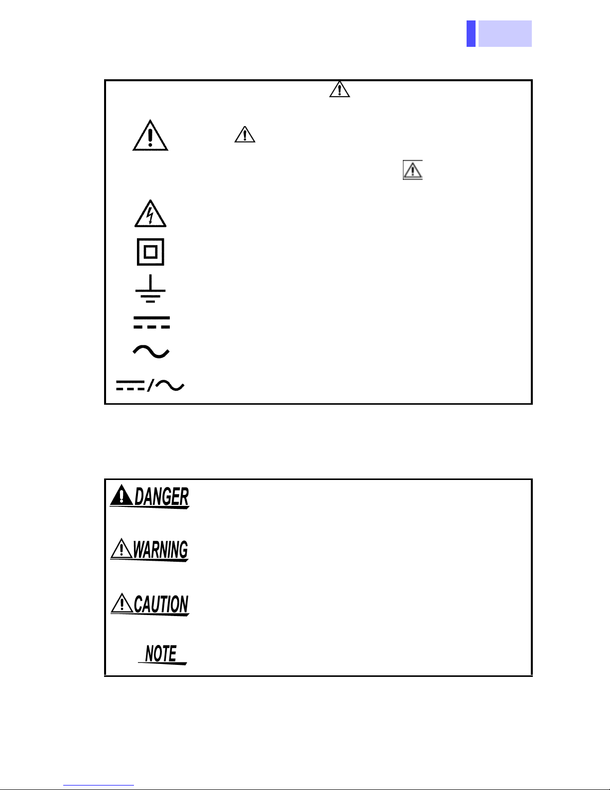
Safety Symbols
In the manual, the symbol indicates particularly important information that the user should
read before using the product.
The symbol printed on the product indicates
that the user should refer to a corresponding topic
in the manual (marked with the symbol) before
using the relevant function.
Indicates that dangerous voltage may be present
at this terminal.
Indicates a double-insulated device.
Indicates a grounding terminal.
Indicates DC (Direct Current).
Safety Notes
Symbols
Indicates AC (Alternating Current).
Indicates DC (Direct Current) or AC (Alternating
Current).
The following symbols in this manual indicate the
relative importance of cautions and warnings.
Indicates that incorrect operation presents an extreme hazard that could result in serious injury or
death to the user.
Indicates that incorrect operation presents a significant hazard that could result in serious injury or
death to the user.
Indicates that incorrect operation presents a possibility of injury to the user or damage to the product.
Advisory items related to performance or correct
operation of the product.
Page 8

Safety Notes
4
Other Symbols
Indicates the prohibited action
Accuracy
We define measurement tolerances in terms of f.s.
(full scale), rdg. (reading) and dgt. (digit) values,
with the following meanings:
f.s.
rdg.
dgt.
(maximum display value or scale length)
The maximum displayable value or the full length
of the scale. This is usually the maximum value of
the currently selected range.
(reading or displayed value)
The value currently being measured and indicated
on the measuring product.
(resolution)
The smallest displayable unit on a digital measuring product, i.e., the input value that causes the
digital display to show a "1".
Page 9
5
Safety Notes
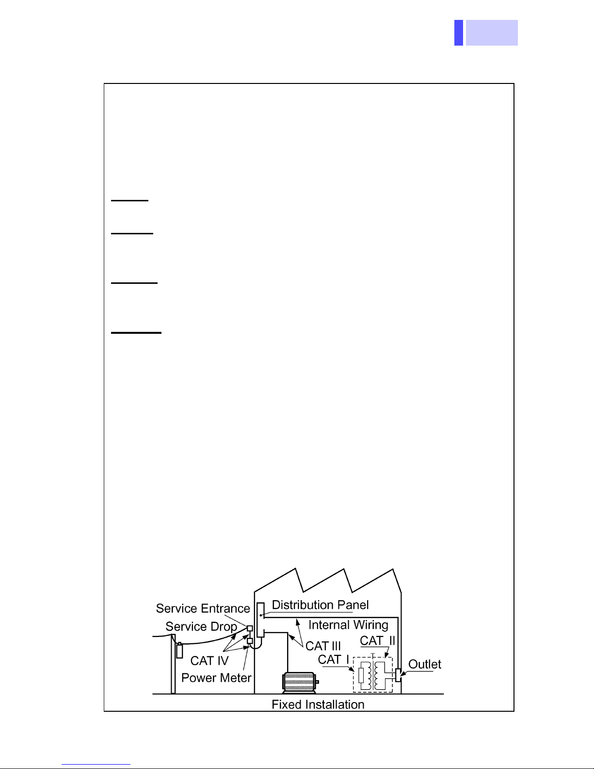
Measurement categories (Overvoltage categories)
This product conforms to the safety requirements for CAT III
600V, CAT II 1000V measurement products.
To ensure safe operation of measurement products, IEC
61010 establishes safety standards for various electrical environments, categorized as CAT I to CAT IV, and called measurement categories. These are defined as follows.
CAT I
trical outlet through a transformer or similar device.
CAT II
an AC electrical outlet by a power cord (portable tools, household appliances, etc.)
CAT III
installations) connected directly to the distribution panel, and
feeders from the distribution panel to outlets.
CAT IV
entrance, and to the power meter and primary overcurrent
protection device (distribution panel).
Higher-numbered categories correspond to electrical environments with greater momentary energy, so a measurement
: Secondary electrical circuits connect ed to an AC elec-
: Primary electrical circuits in equipment connected to
: Primary electrical circuits of heavy equipment (fixed
: The circuit from the service drop to the service
product designed for CAT III environments can endure
greater momentary energy than one designed for CAT II.
Using a measurement product in an environment designated
with a higher-numbered category than that for which the product is rated could result in a severe accident, and must be
carefully avoided.
Never use a CAT I measuring product in CAT II, III, or IV environments.
The measurement categories comply with the Overvoltage
Categories of the IEC60664 Standards.
Page 10

Usage Notes
6
Usage Notes
Follow these precautions to ensure safe operation
and to obtain the full benefits of the various functions.
Inspection before Use
• Before using the product the first time, verify that it
operates normally to ensure that the no damage
occurred during storage or shipping. If you find any
damage, contact your dealer or Hioki representative.
• Before using the product, make sure that the insulation on the test leads is undamaged and that no
bare conductors are improperly exposed. Using
the product under such conditions could result in
electrocution. Replace the test leads with the
specified Hioki Model 9207-10.
Inst a llat ion, Ope ratin g Environm ent, and Handli ng
• To avoid electric shock, do not allow the
product to get wet, and do not use it when
your hands are wet.
• Do not use the product where it may be
exposed to corrosive or combustible
gases. The product may be damaged or
cause an explosion.
Page 11

7
Usage Notes
Observe the following to avoid damage to the
product.
• Installation and Operating Environment
Between 0°C and 40°C; 80% RH or less;
indoors only. Howev er, it can be safely operated
at as low as -10°C.
• Do not store or use the product where it could
be exposed to direct sunlight, high tem perature
or humidity, or condensation.
Under such conditions, the product may be
damaged and insulation may deteriorate so that
it no longer meets specifications.
• Although this product is designed to resist the
ingress of dust and water, it is not entirely wateror dust-proof, so to avoid shoc k or damage, do
not use it in a wet or dusty environment.
The protection rating for the enclosure of this
device (based on EN60529) is *IP54.
• Do not use the product near a device that generates a strong electromagnetic field or electrostatic charge, as these may cause erroneous
measurements.
• To avoid damage to the product , protect it from
vibration or shock during transport and handling,
and be especially careful to avoid dropping.
*IP54 This indicates the degree of protection provided by
the enclosure of the device against use in hazardous locations, entry of solid foreign objects, and
the ingress of water.
5: Protected against access to hazardous parts with
wire measuring 1.0 mm in diameter. Dust-proof
type (The penetration of dust cannot be prevented
completely, but quantities of dust that may hinder
the stated operation of equipment or safety cannot
penetrate the enclosure.)
4: The equipment inside the enclosure is protected
against the harmful effects of water splashed
against the enclosure from any direction.
Page 12
Usage Notes
8
• Adjustments and repairs should be made only
by technically qualified personnel.
• If the protective functions of the product are
damaged, either remove it from s ervice or mark
it clearly so that others do not use it inadvertently.
• To avoid corrosion from battery leakage, remove
the batteries from the product if it is to be stored
for a long time.
• Accurate measurement may be impossible in the
presence of strong magnetic fields, such as near
transformers and high-current conductors, or in
the presence of strong electromagnetic fields
such as near radio transmitters.
• To avoid battery depletion, turn the function
selector OFF after use (the Auto Power Save
feature consumes a small amount of current).
• The indicator appears when ba ttery voltage
becomes low. Replace the batteries as soon as
possible.
Handling the Cables
• The ends of the test leads are sharp. Be careful
to avoid injury.
• To avoid damaging the cables, do not bend or
pull the cables.
• Avoid stepping on or pinching the cable, which
could damage the cable insulation.
Page 13

9
Connection and Measurement
For other precautions and details, see explanations of the measurement procedures.
Use only the specified test lead or clamp-on probe.
Using a non-specified cable may result in incorrect
measurements due to poor connection or other
reasons.
When measuring a breaker
This product should only be connected to the
secondary side of a breaker, so the breaker
can prevent an accident if a short circuit
occurs. Connections should never be made
Usage Notes
to the primary side of a breaker, because
unrestricted current flow could cause a serious accident if a short circuit occurs.
Voltage Measurem ent
• The maximum input voltage is 1000
VDC,1000 Vrms(sin), or 10
ing to measure voltage in excess of the
maximum input could destroy the product
and result in personal injury or de ath.
• The maximum rated voltage between input
terminals and the ground is as follows;
(CAT II) DC 1000 V, AC1000 Vrms (sin) or
10
(CAT III) DC 600 V, AC600 Vrms (sin) or
10
7
V•Hz
7
V•Hz
7
V•Hz. Attempt-
Attempting to measure voltages exceeding
this level with respect to ground could
damage the product and result in personal
injury.
Page 14
Usage Notes
10
Resistance Measurement, Checking the
Continuity or Diode
Never apply voltage to test leads when the
Resistance, Continuity or Diode Check functions are selected. Doing so may damage
the product and result in personal injury.
To avoid electrical accidents, remove power
from the circuit before measuring.
Current Measurement
(When using the optional Clamp-on Probe)
Connect the Clamp-on probe to the product
first, and then to the active lines to be measured.
Observe the following to avoid electric shock
and short circui t s.
• Never attach the clamp-on probe to a circuit that operates at more than 600 V, or
over bare conductors.
• When the Clamp-on probe is opened, do
not allow the metal part of the clamp to
touch any exposed metal, or to short
between two lines.
To avoid electric shock when measuring live
lines, wear appropriate protective gear, such
as insulated rubber gloves, boots and a
safety helmet.
Page 15

11
Usage Notes
• To prevent damage to the product and Clampon probe, never connect or disconnect a sensor
while the power is on.
• Be careful to avoid dropping the Clamp-on
probe or otherwise subjecting them to mechani-
cal shock, which could damage the m ating surfaces of the core and adversely affect
measurement.
• Keep the clamp jaws and core slits free from foreign objects, which could interfere with clamping
action.
Page 16

Usage Notes
12
Page 17

13
1.1 Product Ov e r view
Overview Chapter 1
1.1 Product Overview
This measurement product is a multi-functional
digital multimeter capable of measuring DC and
AC voltages, AC currents, and the resistance, and
checking the diode and continuity.
1.2 Features
Compliance with CE marking requirements
The measurement product is designed to comply
with the international safety standard (IEC61010)
and EMC standards.
Handy and safe digital multimeter (DMM) with
protections against accidents
• No need to replace a test lead; two input termi-
nals are provided
• A fuse and protective resist or between input ter-
minals prevent an accident caused by a short circuit.
• The dustproof and waterproof structure pr events
dust and moisture from entering the product
(IP54).
Current measurement (AC) using a Clamp-on
probe
Displays the measured voltage output of an
optional Clamp-on probe as a current v alue using
a scaling function.
Page 18

1.3 Parts Names and Functions
14
t
t
1.3 Parts Names and Functions
LCD Display
SHIFT Button
RANGE Button
(page 15)
(page 15)
(page 15)
Selects functions
V, mV
CLAMPCurrent measuremen
+ Terminal
Tu rns the power on/off
Red
Connect the 9207-10 TEST LEAD
or optional Clamp-on probes.
Connection method: (page 17)
COM Terminal
Black
When the switch is rotated
clockwise from the OFF position, the power is turned on.
Function Selector
Voltage measuremen
Resistance measurement
Continuity checking
Diode checking
Page 19

15
1.3 Parts Names and Functions
k
-
it
s
-
-
it
I
f
B
f
I
D
f
I
A
c
f
P
i
t:
t
d
-
-
LCD Display
Indicates Auto Power Save is enable
Indicates Autoranging
function
ndicates
HOLD AUTO
unction is enable.
links when on standby
Indicates diode check function
Indicates continuity chec
function
Indicates current mea
surement function
or a trigger
ndicates
C voltage
unction
ndicates
C voltage/
urrent
unction
olarity
ndicator
Decimal point
Indicates low battery voltage
Current measurement un
Lights up when the voltage drops below t he battery accuracy guarantee voltage (2.3±0.15 V)
Clamp-on
probe range
(7-range)
Resistance
and continu
ity check
units
Voltage mea
surement un
Buttons
SHIFT button
• Selects DC/AC ( )
(Voltage measurement [V,mV])
• Selects function; Continuity
check [ ]/ Diode check [ ]/
Resistance measurement [ ]
• Turns the HOLD AUTO func-
*1
tion on/off
• Cancels the Auto Power Save
function
To reset from the Auto Power
Save state, turn off the power
and turn it on again.
(page 29)
*2
(page 31)
RANGE button
• Voltage measurement,
resistance measuremen
Changes the manual
range and auto range
Selects range (manual
range only).
*1
• Current measurement:
Selects the range of the
Clamp-on probe.
*1: Press the button for at leas
1 second.
*2:Turn on the power while
pressing the button, and hol
the button down until a beep
ing sound is generated (pow
er-on option).
.
Page 20

1.3 Parts Names and Functions
16
Page 21

17
Measurement
p
d
to
k
2.1 Connection
Procedures
Observe the following precautions to avoid
electric shock.
• Always verify the appropriate setting of the
function selector before connecting the
test leads.
• Disconnect the test leads from the measurement object before switching the function selector.
2.1 Connection
Chapter 2
Voltage measurement/ Resistance measurement/
Continuity check/ Diode check
Safety cap
9207-10
TEST LEAD
1. Remove the protective ca
from the test lead supplie
with the product.
2. Connec t the red test lead
terminal +, and the blac
test lead to terminal COM.
Connect the test lead to the
Red
9207-10 TEST LEAD
Black
terminals securely.
Page 22

2.1 Connection
18
e
,
al
Current measurement
To perform measurement, an optional Clamp-on probe is
required.
Connect the red plug of th
Clamp-on probe to terminal +
and the black plug to termin
COM.
Connect the plug to the terminals securely.
Red
Clamp-on probe
Black
Page 23

19
2.2 Voltage Measurement
2.2 Voltage Measurement
• The maximum input voltage is 1000
VDC,1000 Vrms(sin), or 10
ing to measure voltage in excess of the
maximum input could destroy the product
and result in personal injury or de ath.
• The maximum rated voltage between input
terminals and the ground is as follows;
(CAT II) DC 1000 V, AC1000 Vrms (sin) or
7
V•Hz
10
(CAT III) DC 600 V, AC600 Vrms (sin) or
7
V•Hz
10
7
V•Hz. Attempt-
Attempting to measure voltages exceeding
this level with respect to ground could
damage the product and result in personal
injury.
• To avoid electrical shock, be careful to
avoid shorting live lines with the test leads.
• For safety, test lead connections must
always be made at the secondary s ide of a
circuit breaker.
The indicated value may vary due to the existence
of induced voltage under no-power conditions.
However, this is not a problem.
Page 24

2.2 Voltage Measurement
20
n
r
r
f
t-
V
e
s
s
t
e
V measurement
AC Volt age
Measurement
Example
mV measurement
DC Volt age
Measurement
1. Move the functio
selector to the V o
mV position ("V" o
"mV" lights up,
lights up).
If you are not sure o
the approximate vol
age level, select
first.
2. When DC voltag
measurement, pres
the SHIFT button.
( lights up)
3. Connect the test lead
to the measuremen
object, and read th
indicated value.
Black
Red
Selecting the manual range ...
Reselecting the auto range
Holding the me asur ed
value
Appearance of O.F
(page 29).................
...............
....
Example
Black
Red
Press RANGE("AUTO" is turned off)
Press RANGE (for at least 1 second)
("AUTO" lights up)
Press SHIFT (for at least 1 second)→
Measurement
Move the test leads away from the measurement objec t.
The measured value exceeds maximum
display counts
420-V range: display up to 4199
1000-V range: display up to 1099
→Intermittent sound→
Page 25

21
2.3 Current Measurement
2.3 Current Measurement
To perform measurement, an optional Clamp-on
probe is required.
Connect the Clamp-on probes to the product
first, and then to the active lines to be measured. Obse rve the followin g to av oid elec tri c
shock and short circuits.
• To avoid short circuits and potentially lifethreatening hazards, never attach the
Clamp-on probe to a circuit that operates
at more than 600 V, or over bare conductors.
• Clamp-on probe should only be connected
to the secondary side of a breaker, so the
breaker can prevent an accident if a short
circuit occurs. Connections should never
be made to the primary side of a breaker,
because unrestricted current flow could
cause a serious accident if a short circuit
occurs.
• When the Clamp-on probe is opened, do
not allow the metal part of the clamp to
touch any exposed metal, or to short
between two lines, and do not use over
bare conductors.
• Never apply v olt age to the Clamp-on probe
when a current measurement function is
selected. Doing so may damage the product and result in personal injury.
Page 26

2.3 Current Measurement
22
• To prevent damage to the product and sensor,
never connect or disconnect a probe while the
power is on.
• Check the position of the range switch of the
Clamp-on probe before taking measurements.
• Make sure the range setting of the product is the
same as that of the Clamp-on probe before starting measurement. If the ranges differ, an accurate current measurement will not be displayed.
• Attach the clamp around only one conductor.
Single-phase (2-wire) or three-phase (3-wire)
cables clamped together will not produce any
reading.
OK
• For details on each Clamp-on probe, see the
respective Instruction Manual.
Page 27

23
1.
l
-
t
s
-
t
-
-
s
When the measurement
range is set to 100A
9010
3255-50
2.3 Current Measurement
Move the function selector to
the CLAMP position.
( lights up)
2. Set the measurement range
of the Clamp-on probe
(option).
If you are not sure of the leve
of the current to be mea
sured, select a large range.
3. Press the RANGE button and
select the same range as tha
of the Clamp-on probe.
LOAD
SOURCE
Conductor
Position the clamp with
the current direction indicator pointing toward
the load side.
The Auto Range function i
not available for current mea
surement.
Make sure the rang e setting of
the product is the same as that
of the Clamp-on probe before
starting measurement.
4. Clamp the measuremen
object, and read the indicated
value.
Change the range in accor
dance with the actual mea
surement. If the range of the
Clamp-on probe is changed
during measurement, change
the range of the product a
well.
Appearance of O.F...............
The measured value exceeds maximum
display counts
10, 100, 1000-A range: display up to 999
20, 200-A range: display up to 1999
50, 500-A range: display up to 499
Page 28

2.4 Resistance Measurement
24
o
e
d
2.4 Resistance Measurement
• Never apply voltage to the test leads
when the Resistance function is
selected. Doing so may damage the
product and result in personal injury.
• To avoid electrical accidents, remove
power from the circuit before measuring.
1. M ove the function selector t
the Ω position.
( lights up)
Black
Selecting the manual range...
Reselecting the auto range
Holding the measured
value
(page 29) ................
Red
....
2. Connec t the test leads to th
measurement object, an
read the indicated value.
Press RANGE("AUTO" is turned off)
Press RANGE (for at least 1 second)
("AUTO" lights up)
Press SHIFT(for at least 1 second)→
Measurement→Intermitt ent sound→
Move the test leads away from the measurement objec t.
Page 29

25
2.5 Continuity Check
o
-
T
e
-
2.5 Continuity Check
• Never apply voltage to the test leads
when the Continuity check function is
selected. Doing so may damage the
product and r esult in personal injury.
• To avoid electrical accidents, remove
power from the circuit before measuring.
1. Move the fu nction selector t
the Ω position.
2. Select Continuity check func
Black
Red
tion
button ( lights up).
()
using the SHIF
3. Connect t he test leads to th
measurement object.
When the continuity (threshold: 45±35 Ω or less) is estab
lished, the beeping sounds
and the resistance is displayed (fixed to the 420-Ω
range).
Page 30

2.6 Diode Check
26
o
n
t-
e
d
a
a
2.6 Diode Check
• Never apply voltage to the test leads
when the Diode Check function is
selected. Doing so may damage the
product and result in personal injury.
• To avoid electrical accidents, remove
power from the circuit before measuring.
1. Move the function selector t
the Ω position.
Cathode Anode
Forward
direction
Black
If displays for both directions
are the same, the following
may have occurred:
• The diode has malfunctioned.
Red
2. Select Diode check functio
()
ton twice ( lights up).
3. Connect the test leads to th
measurement object.
The display shows forwar
voltage (0.15 V to 2.0 V) for
normal diode.
When the diode is connected
in the forward direction (with
beeping sound):
When the diode is invertedly
connected or broken:
pressing the SHIFT
bu
• The forward voltage of the
diode is out of the measurement range.
Page 31

27
3.1 Auto Range Function and Manual Range
Additional
Functions
Chapter 3
3.1 Auto Range Function and Manual
Range Function
Functions
Auto range function_______________________
Auto range function: V/
Manual range function: V/ / CLAMP
The Autoranging function automatically selects the
optimum measurement range.
Turning on the power also switches Autoranging
(AUTO lights up).
on
The range automatically switches up when the dis-
play shows 4200 counts or more, and down when
the display shows less than 400 counts. (A beep
sound is generated when the 3255-50 is switched
to a different range, and decimal point is displayed.)
Page 32

3.1 Auto Range Function a nd Manual Range
28
Manual range function ____________________
Press the RANGE button to active the manual
range function (AUTO is turned off).
Only Manual Range is available for current measurement (CLAMP).
Range selection:
V/ Ω Each pressing of the RANGE button selects the
next larger range. After the largest range, pressing
the select button again returns you to the smallest
range.
CLAMP Each pressing of the RANGE button selects the
next smaller range. After the smallest range,
pressing the select button again returns you to the
largest range.
Switching from Manual Range to Auto
Range:
Press and hold down the RANGE button (for about
1 second). (AUTO lights up)
Page 33

29
3.2 HOLD AUTO Function
e
-
-
is
y
-
)
3.2 HOLD AUTO Function
Functions
Description
(example: )
HOLD
(blinks)
HOLD
(lights up)
Beeping
sound
V/ mV/
Simply moving the test leads away from the measurement object holds the measured value.
This function is useful when it is difficult to read
the displayed value in the current locat ion or both
hands are being used to conduct the measurement.
1. Move the function selector to th
desired position.
2. Pres s the SHIFT button.
(HOLD blinks)
In the measurement of resistance,
O.F is displayed.
3. Connect the test leads to the mea
surement object.
After the measured value is stabi-
lized, an intermittent sound is gener
ated.
(HOLD lights up)
4. When the intermittent sound
heard, move the test leads awa
from the measurement object.
HOLD
(blinks)
The measured value
is held.
The measured value immediately be
fore the test leads are removed is
held.
(HOLD blinks)
Blind zone V/ mV: less than 400 counts
Ω: 4200 counts or more
Canceling the HOLD AUTO mode:
Press SHIFT again. (HOLD is turned off
Page 34

3.3 Overflow Warning Function
30
3.3 Overflow Warning Function
Functions
Description
O.F is displayed and an intermittent sound is ge nerated also in
the cases described below.
Voltage
measurement
Current
measurement
V/ mV/ CLAMP
When the measured value exceeds the maximum indication (4199 counts), O.F is displayed
and an intermittent sound is generated.
Range
1000 V 1099 1100 or more
10/ 100/ 1000 A 999 1000 or more
20/ 200 A 1999 2000 or more
50/ 500 A 499 500 or more
Maximum
display value
O.F display
Example: When the measur ed value exceeds 1099 V in the
AC voltage measurement ( V)
The Overflow Warning function is disabled while
the HOLD AUTO function is on.
Page 35

31
3.4 Auto Power Save Function
3.4 Auto Power Save Function
Functions
Description
All functions
Approximately 10 minutes after completing final
operation, the measurement product automatically enters Power Sa ve mode. When the measurement product is turned on, it automatically
enters Auto Power Save mode (APS lights up).
• In Power Save mode, the LCD is blank but power
is supplied to the measurement product.
• To avoid battery depletion, turn the function
selector OFF after use (the Auto Power Save
feature consumes a small amount of current).
Recovery from Power Save mode:
Turn of f the function selector.
After the measurement product exits Power Save
mode, all conditions are reset . If the measurement
product is to be used for an extended period, Auto
Power Save mode should be canceled in advance.
Canceling the Auto Power Save function:
Turn on the measurement product while pressing
the SHIFT button. (Hold down the button until the
beeping sound is generated.)
The Auto Power Save function is disabled until the
measurement product is turned off (APS is turned
off).
Page 36

3.4 Auto Power Save Function
32
Page 37

33
4.1 General Specifications
Specifications Chapter 4
4.1 General Specifications
General
Measurement
method
AC measurement
system
Function DC voltage ( V), AC voltage( V),
Additional function Auto Range function (AUTO)
Circuit protection Circuit current-limiting resistor
Dual integration
Average rectifying measurement
AC current ( ) (using with the optional
clamp-on probe), Resistance (
Continuity check( ), Diode check( )
(judgment only)
Manual Range function
Hold Auto function (HOLD)
Auto Power Save function (APS)
Battery-Life Warning function
Overflow Warning function (OF)
Protective fuse [Model DMM-44/100, fastacting, Rating 0.44 A/1000 V (AC/DC),
breaking capacity 10 kA (made by Cooper
Bussmann*) *:
Bussmann Division, USA]
Cooper Industries Inc.,
Ω),
Display type TN type LCD, 1/4 duty, dynamic drive
Display elements 3(1/2) dgt. Max. 4199 counts
Units and symbols
1000V AC/DC range 1099 counts
Polarity indicator: "–" sign (automatic)
Overflow indicator: "OF" or "–OF"
Clamp range indicator (10 to 1000)
(AC), (DC), , AUTO, HOLD, ,
, APS, (CLAMP), M, k, m, V, Ω, A
Page 38

4.1 General Specifications
34
General
Range switching Auto/Manual Range
Sampling rate 2.5 S/s
Input terminals +(V, Ω, continuity, diode) terminal
COM terminal
Functions OFF/ V/ mV/ CLAMP/ Ω
Buttons SHIFT, RANGE
Power supply Two manganese (R03) batteries or
two alkaline (LR03) batteries
Battery-life
warning
Dimensions Approx.70W × 145H × 31D mm
Mass Approx. 210 g (7.4 oz) (including batteries)
Operating
environment
Operating temper-
ature and humidity
Storage tempera-
ture and humidity
Accessories Instruction Manual
indicates low battery
(2.3 V±0.15 V or less)
(2.76"W × 5.71"H × 1.22"D)
without protrusions
(
Indoors, altitude up to 2000 m (6562-ft.)
0 to 40°C (32 to 104°F), at 80%RH or less
(non-condensating)
-20 to 40°C (-4 to 104°F), at 80%RH or
less (non-condensating)
40 to 60°C (104 to 140°F), at 70%RH or
less (non-condensating)
T wo R03 manganese batteries
9207-10 TEST LEAD
)
(for monitor )
Options 9010 CLAMP ON PROBE
9371 CARRYING CASE
9018 CLAMP ON PROBE
Page 39

35
4.1 General Specifications
Applicable Standards
Safety EN61010-1:2001
EN61010-031:2002
Pollution Degree 2
Measurement Category CAT III 600 V,
CAT II 1000 V (Anticipated T ransient Overvoltage: 6000 V)
EMC EN61326:1997+A1:1998+A2:2001
+A3:2003
Dustproof and
EN60529:1991 IP54
waterproof
Electrical Chara ct eri st ics
Measurement
accuracy
Accuracy guarantee for temperature and humidity
Regulated power
supply range
Temperature
characteristic
Noise suppression
NMRR
Noise suppression
CMRR
See accuracy table (page 37)
23°C±5°C (73°F± 9°F), 80%RH or less
(non-condensating)
3.4 V or lower (until the mark lights up)
(Measurement accuracy) × 0.1/°C
(except 23°C±5°C)
DCV: 40dB or better (50/60 Hz)
ACV: 40dB or better (DC)
DCV:100dB or better (50/60 Hz)
ACV: 60dB or better (50/60 Hz)
(1 kΩ Unbalance)
Dielectric strength
Maximum input
voltage
Maximum rated
voltage between
input terminals and
ground
Input terminals to case: 5.55 kVrms sin
(50/60 Hz for one minute)
7
1000 VDC/ 1000 Vrms(sin) or 10
V•Hz
1000 VDC/ 1000 Vrms(sin) (CAT II) or
7
10
V•Hz
600 VDC/ 600 Vrms(sin) (CAT III) or
7
10
V•Hz
Page 40

4.1 General Specifications
36
Electrical Characteristics
Rated power
supply voltage
Maximum rated
power
Rated power 4 mVA (Typ) (supply voltage 3.0 VDC,
Power during auto
power saving
Continuous
operating time
3.0 VDC
12 mVA (Max) (supply voltage 3.0 VDC)
in DCV mode)
0.1 mVA (Max)
(supply voltage 3.0 VDC, during Auto
Power Saving)
Approx. 200 hours (in DCV mode, with
R03 manganese batteries)
Approx. 500 hours (in DCV mode, with
LR03 alkaline batteries)
Page 41

37
4.2 Accuracy
4.2 Accuracy
Accuracy Table
(Accuracy guaranteed for one year at 23°C±5°C (73°F±9°F),
80%RH or less.)
(rdg.: displayed value, dgt.: resolution)
Voltage Measurement
mV
V
Range
[V]
420.0 m
4.200
42.00
420.0
1000
Accuracy
±(rdg.)±(dgt.)
±1.0%±4
±1.0%±4
±0.5%±4
±0.7%±4
±0.7%±4
Approx.10 MΩ
Approx.11 MΩ
Approx.10 MΩ
Approx.10 MΩ
Approx.10 MΩ
(50
Approx.10 MΩ
Approx.11 MΩ
Approx.10 MΩ
Approx.10 MΩ
Approx.10 MΩ
mV
V
420.0 m
4.200
42.00
420.0
1000
±2.0%±4
±2.0%±4
±1.2%±4
±1.5%±4
±1.5%±4
Overload protection (for one minute):
7
1000 VDC,1000 Vrms(sin) or 10
V•Hz
Input Impedance
(Frequency range)
to 500 Hz)
Page 42

4.2 Accuracy
38
(rdg.: displayed value, dgt.: resolution)
Current Measurement
(3255-50 only. For accuracy of the combination of the Clamp-on
probe and the 3255-50, add the measurem ent accuracy of the
clamp-on probe)
CLAMP
(ACA)
Range
[A]
10.00
20.00
50.0
100.0
200.0
500
1000
Accuracy
±(rdg.)±(dgt.)
±2.0%±4
±2.0%±4
±2.0%±4
±2.0%±4
±2.0%±4
±2.0%±4
±2.0%±4
Input Impedance
(Frequency range)
Approx.10 MΩ
(50 to 500 Hz)
Overload protection (for one minute):
7
1000 VDC,1000 Vrms(sin) or 10
V•Hz
Resistance Measurement/ Continuity Check/
Diode Check
(Resistance)
Range
[Ω]
420.0
4.200 k
42.00 k
420.0 k
4.200 M
42.00 M
Accuracy
±(rdg.)±(dgt.)
±1.0%±8
±0.7%±4
±1.0%±4
±1.0%±4
±2.0%±4
±5.0%±4
Open terminal
voltage
3.4 V or less
Approx.0.7 V
Approx.0.5 V
Approx.0.5 V
Approx.0.5 V
Approx.0.5 V
Notes
Measurement
current: 850 μA
max.
Varies according to resistance
levels to be
measured.
(Continuity)
420.0 ±1.0%±8 3.4 V or less
Judgment only
(Diode)
(0.15V to 2.00V) 3.4 V or less
Overload protection (for one minute):
1000 VDC,1000 Vrms(sin) or 10
7
V•Hz
Threshold:
45 Ω±35 Ω
Measurement
current:
850 μA max.
Page 43

39
5.1 Replacing the Batteries and Fuses
Maintenace and
Service
Chapter 5
5.1 Replacing the Batteries and Fuses
• To avoid electric shock when replacing the
batteries and fuses, first disconnect the
test leads from the object to be measured.
• Before using the product after replacing
the batteries or fuses, replace the cover
and screw.
Replacing the Batteries
• Do not mix old and new batteries, or different types of batteries. Also, be careful to
observe battery polarity during installation.
Otherwise, poor performance or damage
from battery leakage could result.
• To avoid t he poss ibility of explo si on, do not
short circ ui t, d isas sem bl e or i ncine rate batteries.
• Handle and dispose of batteries in accordance with local regulations.
• The “ ” indicator appears when battery voltage
becomes low. Replace the batteries as soon as
possible.
• Use R03 manganese dry cells or LR03 alkaline
dry cells.
Page 44

5.1 Replacing the Batteries and Fuses
40
Replacing the Fuses
Replace the fuse only with one of the specified characteristics and voltage and current
ratings. Using a non-specified fuse or shorting the fuse holder may cause a life-threatening hazard .
Fuse type:
Model DMM-44/100, Fast-acting, Rating:
0.44 A/1000 V (AC/DC), Breaking capacity:
10 kA (made by Cooper Bussmann)
Be careful not to damage the circuit board or cas e
when changing fuses. If removing the fuse by
hand, be careful not to hurt your nails or fingers.
When measurement cannot be performed, the
fuse may have blown due to excess current. When
the fuse has blown, the beeping sound will not be
generated during a continuity check.
Fuse Protection Circuitry
A 5 Ω protective resistor and 0.44 A safety fuse
(1000 V AC/DC, 10 kA cut-off capacity) are
installed in series with the positive terminal of the
instrument to prevent short-circuit accidents during
voltage measurement of power line circuits. If a
short occurs in the instrument circuitry, current flow
is limited by the protective resistance until the
safety fuse opens. The protect ive resistance limits
the short-circuit current, minimizing arcing at the
tip of the test probe and providing safer operation.
Page 45

41
s
t
e
n
r
-
e
r
)
r
e
t
d
g
r
Front case
Front case
Fuse
5.1 Replacing the Batteries and Fuses
Necessary tool: Phillips screwdrive
1. Disconnect the test lead
from the measuremen
Rear case
circuit, and make sur
the function selector is i
the OFF position.
2. Turn the 3255-50 ove
Rear case
Batteries
and use a Phillips screw
driver to remove the on
retaining screw.
3. Lift and remove the rea
case.
4. Replace the two manga
nese batteries (R03
mounted to the rea
case, or the fus
mounted to the fron
case.
5. Mount the rear case an
tighten the retainin
screw.
Fuse type
Model:DMM-44/100, fast-acting
Rating:0.44 A/1000 V(AC/DC)
Breaking capacity:10 kA
(made by Cooper Bussmann*)
*Cooper Industries Inc., Bussmann Division, USA
Page 46

5.2 Cleaning and Storage
42
5.2 Cleaning and Storage
Cleaning________________________________
• To clean the product, wipe it gently with a soft
cloth moistened with water or mild detergent.
Never use solvents such as benzene, alcohol,
acetone, ether, ketones, thinners or gasoline, as
they can deform and discolor the case.
• Wipe the LCD gently with a soft, dry cloth.
Storage_________________________________
To avoid corrosion from battery leakage, remove
the batteries from the product if it is to be stored for
a long time.
Page 47

43
5.3 Service
• Adjustments and repairs should be made only by
technically qualified personnel.
• If the product seems to be malfunctioning, confirm that the batteries are not discharged, and
that the test leads, clamp-on probes, and fuse
are not open circuited before contacting your
dealer or Hioki representative.
• When sending the product for r epair, remove the
batteries and pack carefully to prevent damage
in transit. Include cushioning material so the
instrument cannot move w ithin the package. Be
sure to include details of the problem. Hioki cannot be responsible for damage that occurs during
shipment.
5.3 Service
Page 48

5.3 Service
44
Page 49

Page 50

Page 51

HIOKI 3255-50 DIGITAL HiTESTER
Instruction Manual
Publication date: September 2006 Revised edition 1
Edited and p ublished by HIOKI E .E. CORPO RATION
Technical Support Section
All inquiries to International Sales and Marketing De-
partment
81 Koizumi, Ueda, Nagano, 386-1192, Japan
TEL: +81-268-28-0562 / FAX: +81-268-28-0568
E-mail: os-com@hioki.co.jp
URL http://www.hioki.co.jp/
Printed in Japan 3255AD981-01
• All reasonable care has been taken in the production
of this manual, but if you find any points which are
unclear or in error, please contact your supplier or the
International Sales and Marketing Department at
HIOKI headqu arte rs.
• In the interests of product development, the contents
of this manual are subject to revision without prior
notice.
• Unauthorized reproduction or copying of this manual
is prohibited.
Page 52

HEAD OFFICE
81 Koizumi, Ueda, Nagano 386-1192, Japan
TEL +81-268-28-0562 / FAX +81-268-28-0568
E-mail: os-com@hioki.co.jp
URL http://www.hioki.co.jp/
HIOKI USA CORPORATION
6 Corporate Drive, Cranbury, NJ 08512, USA
TEL +1-609-409-9109 / FAX +1-609-409-9108
3255D981-01 06-09H
Printed on recycled paper
 Loading...