

Page 1

3255
DIGITAL HiTESTER
Instruction Manual
October 2000 Edition 1 Printed in Japan
3255A981-00 00-10-H
Introduction
Thank you for purchasing the Hioki Model 3255 DIGITAL HiTESTER.
To obtain maximum performance from the instrument, please read
this manual first, and keep it handy for future reference.
Specifications
DC Voltage function ( .V/mV)
Range Accuracy Input Impedance Remarks
320.0 mV
3.200 V
32.00 V
320.0 V
600 V
0.5%rdg. 4dgt.
0.5%rdg. 4dgt.
1.3%rdg. 4dgt.
1.3%rdg. 4dgt.
1.3%rdg. 4dgt.
Approx. 10 MΩ
Approx. 11 MΩ
Approx. 10 MΩ
Approx. 10 MΩ
Approx. 10 MΩ
Response time: Approx. 2 sec
AC Voltage function ( .V/mV)
Range Accuracy Input Impedance Remarks
320.0 mV
3.200 V
32.00 V
320.0 V
600 V
2.0%rdg. 8dgt.
2.0%rdg. 8dgt.
2.0%rdg. 8dgt.
2.0%rdg. 8dgt.
2.0%rdg. 8dgt.
Approx. 10 MΩ
Approx. 11 MΩ
Approx. 10 MΩ
Approx. 10 MΩ
Approx. 10 MΩ
Measurement Frequency
Range: 50 Hz to 500 Hz
Response time: Approx. 2 sec
Resistance Measurement function (ΩΩΩΩ)
Range Accuracy Open Terminal
Voltage
Full Scale Response time
320.0 Ω
3.200 kΩ
32.00 kΩ
320.0 kΩ
3.200 MΩ
32.00 MΩ
1.5%rdg. 6dgt.
1.5%rdg. 4dgt.
1.5%rdg. 4dgt.
1.5%rdg. 4dgt.
1.5%rdg. 4dgt.
10.0%rdg. 4 dgt.
1.7 V or less
0.45 V or less
0.45 V or less
0.45 V or less
0.45 V or less
0.45 V or less
3149
3239
3249
3249
3249
3249
Approx. 3 sec
Approx. 3 sec
Approx. 3 sec
Approx. 3 sec
Approx. 5 sec
Approx. 20 sec
Continuity Check function ( )
Accuracy Open Terminal
Voltage
Threshold
level
Response time
2.5%rdg. 6dgt.
1.7 V or less 250 Ω or less Approx.0.2 sec
Diode Check function ( )
Accuracy Open Terminal
Voltage
Measurement
Current
Response time
5.0%rdg. 4dgt.
1.7 V or less 1.0 mA or less Approx. 2 sec
Measurement Method Dual integration
Display Type TN type LCD, 1/3 duty, dynamic drive, 12-mm character
height, Max. 3249 counts (600 counts only in 600 V range)
DisplayElements Polarity indicator: "-" sign (automatic)
Overflow indicator: "OF" or "-OF"
Other indicators: units, functions
Range Switching Auto/Manual Range (single range for mV, continuity and
diode check)
Function Selector Rotary selector
Input Terminals + and COM terminals (2 terminals)
Sampling Rate 2.5 times/sec
Size & Weight 70Wx145H x 31D mm (2.76"x5.71" x 1.22")(without
protrusions), 200 g (7.1 oz.) (within battery)
Accessories 9185 TEST LEADS, 9371 CARRYING CASE,
Instruction Manual
Power Supply Rated supply voltage: 1.5 V DC x 2, R03 manganese x 2
Maximum rated working
Voltage
600 V DC/AC rms (sine wave) or 10
7
VHz (for 1 min.), for all
functions
Dielectric Strength Input terminals to case: 5.55 kVrms(50/60-Hzsinewavefor
one minute)
Noise Suppression NMRR: DC -40 dB or better (50/60 Hz)
CMRR: DC -100 dB or better (50/60 Hz)
AC -60 dB or better (50/60 Hz)
Rated Power 5.0 mW typ. (DC Voltage function, from two 1.5 V batteries)
6.0 mW typ. (AC Voltage function, from two 1.5 V batteries)
0.15 mW typ. (Auto Power Saving, from two 1.5 V batteries)
Maximum Rated Power 6.0 mVA
Battery StatusIndicator indicates lowbattery (< 1.2V 0.1 V)
Continuous Operating
Time
Approx. 400 hours (DC Voltage function)
Approx. 250 hours (AC Voltage function)
Operating Temperature
& Humidity
0to40 (32to104 ) at 80% RH or less (non-condensating)
Storage Temperature &
Humidity
-20to60 (-4 to 140 ) at 70% RH or less (non-condensating)
Temperature
Characteristic
(Measurementaccuracy) 0.1/
Operating Environment Indoors, <2000 m (6562 feet) ASL
Dust and Water
Protection
Equivalent to JIS Protection Type Class 4 (however,
instrument operation is not guaranteed when wet)
Electromagnetic
Radiation Susceptibility
4% f.s. or less at 3 V/m electromagnetic radiation
Safety EN61010-1:1993 Polution Degree 2, Overvoltage Category III
(Anticipated Transient Overvoltage: 6000 V), EN61010-2-031:1994
EMC EN55011:1991, EN50082-1:1992
Safety
DANGER
This device is designed to conform to IEC 61010 Safety Standards, and
has been thoroughly tested for safety prior to shipment. However,
mishandling during use could result in injury or death, as well as damage
to the instrument. Be certain that you understand the instructions and
precautions in the manual before use. We disclaim any responsibility for
accidents or injuries not resulting directly from product defects.
In the manual, the symbol indicates particularly important
information that the user should read before using the
instrument.
The
symbol on the instrument indicates that the user
should refer to a corresponding topic in the manual (marked
with the
symbol) before using the relevant function.
Indicates a device that is protected by double or
supplemental insulation.
Indicates direct current (DC).
Indicates alternating current (AC).
Indicates both DC and AC.
Indicates a protective ground terminal.
DANGER
Indicates that incorrect operation presents an extreme
hazard that could result in serious injury or death to the
user.
WARNING
Indicates that incorrect operation presents a significant
hazard that could result in serious injury or death to the
user.
CAUTION
Indicates that incorrect operation presents a possibility of
injury to the user or damage to the instrument.
NOTE
Advisory items related to performance or correct
operation of the equipment.
Usage Notes
WARNING
To avoid electric shock, do not allow the instrument to get wet,
and do not use it when your hands are wet.
Do not use the instrument where it may be exposed to corrosive
or combustible gases. The instrument may be damaged or cause
an explosion.
CAUTION
Although this instrument is designed to resist ingress of dust and
water, it is not entirelyor water- or dust-proof, so to avoid shock or
damage, do not use it in a wet or dusty environment.
This instrument is designed for indoor use, and operates reliably from 0
to 40
.
Do not store or use the instrument where it could be exposed to direct
sunlight, high temperature or humidity, or condensation. Under such
conditions, the instrument may be damaged and insulation may
deteriorate so that it no longer meets specifications.
Do not use the instrument near a device that generates a strong
electromagnetic field or electrostatic charge, as these may cause
erroneous measurements.
To avoid damage to the instrument, protect it from vibration and shock
during transport or handling. Be especially careful to avoid dropping.
If the protective functions of the instrument are damaged, either
remove it from service or mark it clearly so that others do not use it
inadvertently.
Adjustments and repairs should be made only by technically qualified
personnel.
NOTE
Accurate measurement may be impossible in the presence of strong
magnetic fields such as near transformers and high-current conductors
or in the presence of strong electromagnetic fields such as near radio
transmitters.
To avoid battery depletion, turn the function selector OFF after use (the
Auto Power Save feature consumes a small amount of current).
The indicator appears when battery voltage becomes low. Replace
the batteries as soon as possible.
To avoid corrosion from battery leakage, remove the batteries from the
instrument if it is to be stored for a long time (several months or more).
Replacing the Batteries
WARNING
To avoid electric shock when replacing the batteries, first
disconnect the test leads from any measurement object.
Before using the instrument after replacing the batteries, replace
the cover and screw.
Do not mix old and new batteries, or different battery types. Also,
be careful to observe battery polarity during installation.
Otherwise, poor performance or damage from battery leakage
could result.
To avoid the possibility of explosion, do not short circuit,
disassemble or incinerate batteries.
Handle and dispose of batteries in accordance with localregulations.
Batteries
1
2
Packing
3
Replacing the Fuse
CAUTION
If the fuse blows, do not attempt to replace it or repair the instrument:
contact your dealer or Hioki representative. To determine if the fuse has
blown, check whether the beeper sounds when the test leads are shorted
during a continuity check.
Initial Inspection
When you receive the instrument, inspect it carefully to ensure that no
damage occurred during shipping. If damage is evident, or if it fails to operate
according to the specifications, contact your dealer or Hioki representative.
Preliminary Checks
Before using the instrument, make sure that the insulation on the test leads is
undamaged and that no bare conductors are improperly exposed. Using the
instrument in such conditions could cause an electric shock. Replace the test
leads with the specified Hioki Model 9185.
Maintenance and Service
To clean the instrument, wipe it gently with a soft cloth moistened with
water or mild detergent. Never use solvents such as benzene, alcohol,
acetone, ether, ketones, thinneror gasoline, as they can deform and
discolor the case.
If the instrument seems to be malfunctioing, confirm that the batteries are
not discharged or the test leads broken before contacting your dealer or
Hioki representative.
Accuracy Chart
(23 5 , 80% RH or less, non-condensating)
Response Time: Transition time from the lowest range to the measurement
range, plus display settling time.
Overload protection is 600 V AC/DC rms (sine wave) or 10
7
V Hz for all
functions and ranges.
General
Electrical Characteristics
Environmental Conditions
Standards Conformance
Follow these precautions to ensure safe operation and to obtain the full
benefits of the various functions.
Overvoltage Categories (CAT)
This device conforms to the safety requirements for CAT III measurement
instruments. To ensure safe operation of measurement instruments, IEC
60664 establishes safety standards for various electrical environments,
categorized as CAT I to CAT IV, and called overvoltage categories. These are
defined as follows.
CAT I: Secondary electrical
circuits connected to an AC
electrical outlet through a
transformer or similar device.
CAT II: Primary electrical
circuits in equipment connected to
an AC electrical outlet by a power
cord (portable tools, household appliances, etc.)
CAT III: Primary electrical circuits of heavy equipment (fixed installations)
connected directly to the distribution panel, and feeders from the distribution
panel to outlets.
CAT IV: The circuit from the service drop to the service entrance, and to the
power meter and primary overcurrent protection device (distribution panel).
Higher-numbered categories correspond to electrical environments with
greater momentary energy, so a measurement instrument designed for CAT
III environments can withstand greater momentary energy than one designed
for CAT II. Using a measurement instrument in an environment designated
with a higher-numbered category than that for which the instrument is rated
could result in a severe accident, and must be carefully avoided.
This manual contains information and warnings essential for safe operation of
the instrument and for maintaining it in safe operating condition. Before using
the instrument, be sure to carefully read the following safety notes.
Safety symbols
The following symbols in this manual indicate the relative importance of
cautions and warnings.
1. Place the instrument back-side up, and remove
the Philips screw affixing the rear cover.
2. Remove the rear cover.
3. Replace both batteries.
4. Replace the rear cover back to keep the
dustproof and waterproof devices good condition,
attach the packing correntry without fail.
5. Replace the screw to affix the rear cover.
Fuse Protection Circuitry
A10Ω protective resistor and 1 A safety fuse (600 V AC, 100 kA cut-off
capacity) are installed in series with the positive terminal of the instrument to
prevent short-circuit accidents during voltage measurement of power line
circuits. If a short occurs in the instrument circuitry, current flow is limited by
the protective resistance until the safety fuse opens. The protective resistance
limits the short-circuit current, minimizing arcing at the tip of the test p robe
and providing safer operation.
Page 2
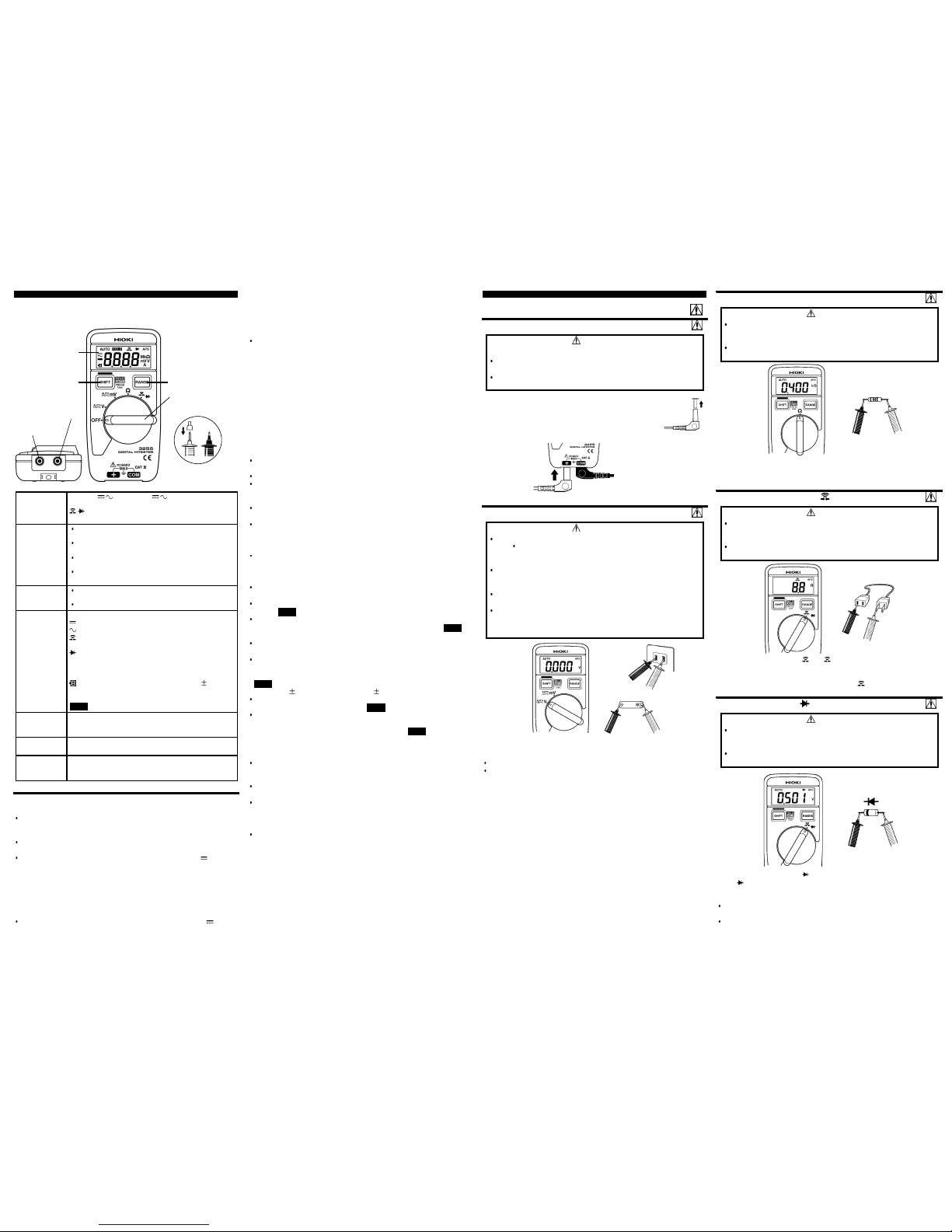
Parts Names and Functions
LCD (Display)
RANGE Button
Function Selector
SHIFT Button
COM Terminal
+Terminal
Test Leads
Red+ Black-
Safety Cap
Function
Selector
V (AUTO/
/ ), mV (AUTO/ / ): Auto Voltage/DC/AC
ΩΩΩΩ: Resistance
: Continuity/Diode Check
OFF: Power Off
SHIFT Button
For the Voltage (V, mV) function: switches between
Auto Voltage, AC and DC
Switches between Continuity and Diode Check
functions
Starts and cancels the Auto-Hold function (refer to the
Auto-Hold function description)
Cancels the Auto Power Save function (refer to "Auto
Power Save")
RANGE Button
Selects between Manual and Autorangingswitching
(refer to "Autoranging Function")
Selects the range during Manual Range operation
LCD (Display) . : Decimal point
: Indicates DC voltage function
: Indicates AC voltage function
: Indicates continuity during Continuity Check
function
: Indicates Diode Check function
AUTO
: Indicates Autoranging, orAuto Voltage
function when blinking
APS
: Indicates Auto Power Save is enabled
: Indicates low battery voltage (1.2 0.1 V)
mV,V
: Voltage and diode check units
ΩΩΩΩ,kΩΩΩΩ,MΩΩΩΩ : Resistance and continuity check units
HOLD
: Lights when the Auto-Hold function is enabled
+Terminal This instrument is a two-terminal design, so test lead
connections do not need to be changed when changing
functions. Connect the RED lead here.
COM Terminal This is the common terminal for all functions. Connect
the BLACK lead here.
Safety Cap The safety cap minimizes the amount of exposed metal
at the probe tip, but the probe can also be used without
the cap.
Other Functions
Measurement Procedure
Measurement Procedure
DANGER
Observe the following precautions to avoid electric shock.
Always verify the appropriate setting of the function selector
before connecting the test leads.
Disconnect the test leads from the measurement object before
switching the function selector.
Black-
Red+
Voltage Measurement (V)
DANGER
The maximum rated voltage is 600 V DC/AC rms (sine wave), or
10
7
V Hz. Attempting to measure voltage in excess of the
maximum rated voltage could destroy the instrument and injure or
kill the user.
Do not connect the test leads while voltage is present: a short
circuit could result and cause injury. Pay careful attention when
making measurements.
For safety, test lead connections must always be made at the
secondary side of a circuit breaker.
The maximum rated voltage between input terminals and ground
is 600 V AC/DC rms (sine wave). Attempting to measure voltages
exceeding 600 V with respect to ground could damage the
instrument and injure the user.
DC Voltage
Measurement
AC Voltage
Measurement
Red+Black-
Resistance Measurement (ΩΩΩΩ)
DANGER
Never apply voltage to the test leads when the Resistance function
is selected. Doing so could damage the instrument and injure the
user.
To avoid electric shock, remove power from the circuit under test
before measuring.
Black-
Red+
Continuity Checking ( )
DANGER
Never apply voltage to the test leads when the ContinuityCheck
function is selected. Doing so could damage the instrument and
injure the user.
To avoid electric shock, remove power from the circuit under test
before measuring.
Red+
Black-
Diode Checking ( )
DANGER
Never apply voltage to the test leads when the Diode Check
function is selected. Doing so could damage the instrument and
injure the user.
To avoid electric shock, remove power from the circuit under test
before measuring.
Black-
Red+
Anode
Cathode
Auto Voltage Function
This function automatically selects the voltage range according to the
voltage being measured, and automaticallyselects DC or AC voltage
measurement.
Setting the function selector to V or mV enables the Auto Voltage function
(the AUTO indicator appears blinking).
When the V function is selected, measurement of DC voltage ( ) begins.
Automatic switching from DC to AC occurs at a preset threshold in the
range of two to ten volts (at 50 Hz) AC. If the measured AC voltage
exceeds this threshold, the instrument switches to AC Voltage function. If
the measured AC voltage drops below about 1 V on the display, the
instrument switches back to DC Voltage function. The actual voltage level
at which the AC voltage function switches to DC is frequency dependent,
and is approximately equal to [frequency/5] volts, or less.
When the mV function is selected, measurement of DC voltage ( ) begins.
Automatic switching from DC to AC occurs at a preset threshold in the
range of two to ten volts (at 50 Hz) AC. If the measured AC voltage
exceeds this threshold, the instrument switches to AC Voltage function. If
the measured AC voltage drops below about 10 mV on the display, the
instrument switches back to DC Voltage function. The actual voltage level
at which the AC Voltage function switches to DC is frequency dependent,
and is approximately equal to [frequency/5+20] volts, or less.
Disabling the Auto Voltage Function
Press SHIFT to enable manual AC/DC switching.
Press RANGE to enable manual range selection (AC or DC is displayed
when the button is pressed).
NOTE
In the Auto-Voltage function, AC measurement is automatically selected when
an input waveform exceeds the +/- threshold in both polarities. Therefore the
auto-voltage switching function may not work properly when measuring an AC
voltage with significant DC offset.
The AC/DC detection process occurs when measurement starts, so if the
input changes from AC to DC during measurement, the DC Voltage function
may not be selected automatically.
Autoranging Function
The Autoranging function automatically selects the optimum measurement
range.
The AUTO indicator appears during Autoranging.
The range automatically switches up when the display shows 2800 to 3249
counts or more, and down when the display shows 269 counts or less. (3.2
kΩ range: 259 counts)
The Autoranging function is not available in the millivolt (mV) range, or in
the Continuity or Diode Check functions.
Disabling Autoranging
Press RANGE to switch to Manual Ranging (the AUTO indicator
disappears)
The measurement range can then be selected by the RANGE button.
Enabling Autoranging
Hold RANGE for 1 seconds.
Auto-Hold Function
This function displays and holds either the maximum voltage or minimum
resistance measurement.
Hold the SHIFT button for one second to enable Auto-Hold (a beep sounds
and the HOLD indicator appears).
To cancel Auto-Hold:
Hold the SHIFT button again for one second (a beep sounds and HOLD
indicator disappears).
When measuring voltage, the display remains unchanged as long as the
measured value is within the dead zone (the indicator blinks).
When the measured voltage reaches or exceeds the dead zone, the new
value is displayed and a beep sounds, after which the display remains
unchanged until another measured value exceeds the displayed value (the
HOLD indicator appears).
Dead zone:
270 counts in 3.2 V range, 30 counts in all other ranges.
When measuring resistance, the display remains unchanged as long as the
measured value is "OF" [overflow ](the HOLD indicatorblinks).
When a measurable resistance is present, the value is displayed and a
beep sounds, after which the display remains unchanged until another
measured value is less than the displayed value (the HOLD indicator
lights).
Auto Power Save Function
This function activates the power save state 30 minutesafter the last
operation. In the power save state, the LCD is blanked, but power is not
completely turned off.
Auto Power Save is automatically enabled when the instrument is turned on
(the APS indicator appears).
Exiting the Power Save State
Either turn the Function selector, or press SHIFT or RANGE.
All selections are reset when exiting the Power Save State, so stored data
is invalid. For long-term operation, disable Auto Power Save beforehand.
Disabling Auto Power Saving
Hold the SHIFT button down while turning the instrument on, and keep
holding it (for about two seconds) until a beep sounds.
The APS indicator is not displayed, and Auto Power Saving is disabled until
the instrument is turned off.
Preparation for Measurement
1. The safety caps are attached to the test leads. Remove
these caps before connecting in the unit.
2. Firmly connect the RED test lead to the + terminal,and the
BLACK test lead to the COM terminal.
1. Set the function selector to V or mV (if AUTO is blinking, the Auto Voltage
function will select AC or DC automatically).
2. Connect the test leads to the measurement object, and read the display.
To select between Auto Voltage, AC and DC volts, press the SHIFT button.
Press the RANGE button to select the range manually.
Hold RANGE for one seconds to re-enable Autoranging (AUTO appears).
1. Set the function selector to Ω.
2. Connect the test leads to the object to be measured, and read the display.
Press the RANGE button to select the range manually.
To re-enable Autoranging, hold RANGE for one seconds.
1. Set the function selector to
(the , Ω indicator appear).
2. Connect the test leads to the object to be measured. Resistance is
displayed when checking continuity (320 Ω range).
3. When the circuit is closed (250 Ω or less), the
indicator appears and a
beep sounds.
1. Set the function selector to
and press the SHIFT button
(the
indicator appears).
2. Connect the red test lead to the diode's anode, and the black test lead to
the cathode.
The display shows forward voltage (0.4 to 0.7 V) for a normal diode. In the
opposite polarity, the open-terminal voltage (1.7 V or less) is displayed.
The display shows about 0 V if the diode is shorted, and the open-terminal
voltage in both directions (3.2 V range) if the diode is open.
 Loading...