

1 34
2
Warranty
Warranty malfunctions occurring under conditions of normal use in conformity with the Instruction Manual and Product Precautionary Markings will be repaired free of charge. This warranty is valid for a period
of three (3) years from the date of purchase. Please contact the distributor from which you purchased the product for further information on
warranty provisions.
Introduction
Thank you for purchasing the HIOKI 3246-60 PENCIL HiTESTER. To obtain maximum performance from the product,
please read this manual first, and keep it handy for future reference.
Overview
The 3246-60 is a pencil-shaped digital multimeter designed to
measure DC/AC voltage and resistance, and conduct con tinui t y
and diode checks. Compact, safe, and easy to use, the 3246-60
meets all CATIV 300 V, CATIII 600 V safety requirements. Probe
leads are wound around the protrusions on the rear. The unit also
features a built-in light to illuminate the object to be measured.
Initial Inspection
When you receive the product, inspect it carefully to ensure
that no damage occurred during shipping. If damage is evident,
or if it fails to operate according to the specifications, contact
your dealer or Hioki representative.
Preliminary Checks
• Before using the product the first time, verify that it operates
normally to ensure that the no damage occurred during storage or shipping. If you find any damage, contact your dealer
or Hioki representative.
• To prevent an electric shock accident, confirm that the white or
red portion (insulation layer) inside the cable is not exposed. If
a color inside the cable is exposed, do not use the cable.
Using the product in such conditions could cause an electric
shock, so contact your dealer or Hioki representative for repair.
Maintenance and Service
• To clean the product, wipe it gently with a soft cloth moistened with water or mild detergent. Never use solvents such
as benzene, alcohol, acetone, ether, ketones, thinners or
gasoline, as they can deform and discolor the case.
• If the product seems to be malfunctioning, confirm that the
batteries are not discharged, and contact your dealer or Hioki
representative.
Follow these precautions to ensure safe operation and to
obtain the full benefits of the various functions.
Measurement categories
This product complies with CAT IV (300 V), CAT III (600 V), CAT II
(600 V) safety requirements.
To ensure safe ope rati on of m easurement products, IEC 61010 establishes safety standards for various electrical environments, categorized as CAT II to CAT IV, and called measurement categories.
CAT II:
Primary electrical circuits in
equipment connected to an
AC electrical outlet by a power
cord (portable tools, household appliances, etc.) CAT II
covers directly measuring
electrical outlet receptacles
.
CAT III:
Primary electrical circuits of
heavy equipment (fixed installations) connected directly to the dis-
tribution panel, and feeders from the distr ibution p a nel to o utlet s.
CAT IV:The circuit from the service drop to the service entrance, and
to the power meter and primary overcurrent protection device
(distribution panel).
Using a measurement instrumentin an environment designated with a
higher-numbered category than that for which the instrument is rated
could result in a severe accident, and must be carefully avoided.
Use of a measurement instrument that is not CAT-rated in CAT II to
CAT IV measurement applications could result in a severe accident,
and must be carefully avoided.
Safety Symbol
Symbols for Various Standards
This manual contains information and warnings essential for
safe operation of the product and for maintaining it in safe
operating condition. Before using the product, be sure to carefully read the following safety notes.
Handling the Sleeve of test lead
Handling the Cap (yellow) of Pencil Hitester
Handling the Test Leads
General
3246-60
PENCIL HiTESTER
Instruction Manual
(3246-61)
Safety
This instrument is designed to comply with IEC 61010
Safety Standards, and has been thoroughly tested for
safety prior to shipment. However, mishandling during
use could result in injury or death, as well as damage to
the instrument Using the instrument in a way not
described in this manual may negate the provided safety
features. Be certain that you understand the instructions
and precautions in the manual before use. We disclaim
any responsibility for accidents or injuries not resulting
directly from instrument defects.
In the manual, the symbol indicates particularly important
information that the user should read before using the product.
The symbol printed on the product indicates that the user
should refer to a corresponding topic in the manual (marked
with the symbol) before using the relevant function.
Indicates a double-insulated device.
Indicates AC (Alternating Current).
Indicates DC (Direct Current).
Indicates DC (Direct Current) or AC (Alternating Current).
This symbol indicates that the product conforms to safety
regulations set out by the EC Directive.
WEEE marking:
This symbol indicates that the electrical and electronic
appliance is put on the EU market after August 13, 2005,
and producers of the Member States are required to display it on the appliance under Article 11.2 of Directive
2002/96/EC (WEEE).
Indicates that incorrect operation pre s ents an extreme hazard that could result in serious injury or death to the user.
Indicates that incorrect operation presents a significa nt haz ard that could result in serious injury or death to the user.
Indicates that incorrect operation presents a possibility of
injury to the user or damage to the product.
Advisory items related to performance or correct operation
of the product.
Usage Notes
• To avoid electric shock, do not allow the product to get
wet, and do not use it when your hands are wet.
• Do not use the product where it may be exposed to corrosive or combustible gases. The product may be damaged or cause an explosion.
• To avoid electric shock when measuring live lines, wear
appropriate protective gear, such as insulated rubber
gloves, boots and a safety helmet.
• Do not store or use the product where it could be exposed
to direct sunlight, high temperature or humidity, or condensation. Under such conditions, the product may be damaged
and insulation may deteriorate so that it no longer meets
specifications.
• This product is not designed to be entirely water- or dust-proof.
To avoid damage, do not use it in a wet or dusty environment.
• This product is designed for indoor use, and operates reliably from 0°C to 40°C.
• To avoid damage to the product, protect it from vibration or
shock during transport and handling, and be especially care ful to avoid dropping.
• Do not use the product near a device that generates a strong
electromagnetic field or electrostatic charge, as these may
cause erroneous measurements.
• To avoid damagin g the test leads, do not bend or pull th e leads.
• If the protective functions of the product are damaged, eithe r
remove it from service or mark it clearly so that others do not
use it inadvertently.
• Accurate measurement may be impossible in the presence of
strong magnetic fields, such as near transformers and highcurrent conductors, or in the presence of strong electromagnetic fields such as near radio transmitters.
• To avoid battery depletion, turn the Function Selector OFF
after use (the Auto Power Save feature consumes a small
amount of current).
• The indicator appears when battery voltage becomes low.
Replace the batteries as soon as possible.
• To avoid cor rosion from bat tery lea kage, remo ve the batter ies
from the product if it is to be stored for a long time.
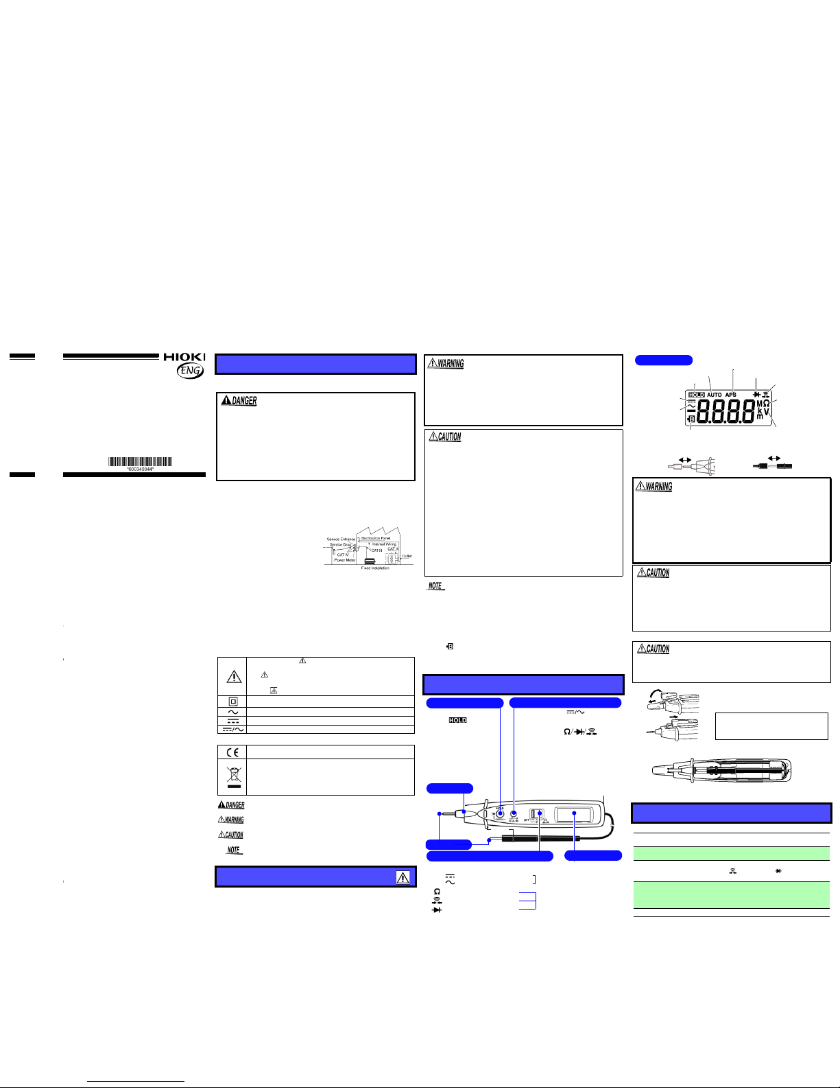
Parts Names
• Selects DC/AC ( V)
(Press the select button for at least
1 second in manual ranging mode.)
• Selects mode ( ).
(Press the select button for at least
1 second in manual ranging mode.)
• Changes to the manual range function. (Turn on the power while
pressing the select button.)
• Selects range (in manual ranging
mode).
OFF
Power Off (Power is turned ON in any position other than OFF.)
V
: DC voltage function (DCV)
: AC voltage function (ACV)
Select with the select button
Resistance function
Select with the select buttonContinuity Check function
Diode Check function
Black ()
Red (+)
• Holds the measurement
value ( lights up).
• Cancels the Auto-Power
Save function (APS).
(Turn on the power while
pressing HOLD.)
• Turns on the light.
(Press HOLD for at least
1 second.)
Penlight
Select Button
LCD Display
Function Selector
HOLD Button
Barrier
Test Leads
Hole for attaching your own
strap for greater portability.
Removable sleeves can be attached to the metal pins at
the ends of the test leads. To prevent a short circuit accident, be sure to use the test leads with the sleeves
attached when performing measurements in the CAT III
and CAT IV measurement categories. Remove the sleeves
from the test leads when performing measurements in the
CAT II measurement category.
For details on measurement categories, see "Measurement categories") in the instruction manual.
• The tips of the metal pins are sharp, so take care not to injure yourself.
• When performing measurements with the sleeves attached,
be careful to avoid damaging the sleeves.
• If the sleeves are inadvertently removed during measurement, be especially careful in handling the test leads to
avoid electric shock.
Observe the following to avoid damage to the product.
• Do not pull the cap with excessive force.
• Replace the cap when not using the product.
Specifications
Measurement
Method
Dual integration
AC Measurement
System
Average rectifying measurement
Function
DC voltage (DCV), AC voltage (ACV), Resistance (),
Continuity check( ), Diode check( )(Forward direction/Reversed direction judgment only)
Additional
Function
Auto Range function, Manual Range function, Hold function, Auto Power Save function (APS), Battery-Life Warning function, Overflow Warning function, Penlight function,
LCD Backlight function
Display Type TN type LCD, 1/4 duty, dynamic drive
LCD Display
Indicates Continuity Check function
Indicates during
Resistance measurement and
Continuity check
Indicates during
Voltage measurement
Indicates Auto Power Save is enabled
Indicates Diode Check function
Indicates DC
voltage function
Indicates AC
voltage function
Indicates Autoranging
Indicates HOLD function
Indicates Battery-Life Warning. (Accuracy is not
guaranteed when the indicator is on.)
When using the 3246, remove the
cap and securely fasten the cap to
the rear, as shown in the figure.
Cap
When removing the cap, be careful
not to prick your finger with the tip
of the lead.
Pull
When storing the 3246-60 test lead (black), be sure to wind
the lead around the protrusion on the rear.
www.GlobalTestSupply.com
Find Quality Products Online at: sales@GlobalTestSupply.com
5 78
6
Accuracy (Accuracy guaranteed for one year at 23°C±5°C (73°F±9°F),
80%RH or less.) Battery low display is off.
*1:Overload protection is 600 V DC/AC rms (sine wave) or 3x10⁶ VHz
(for 1 min.), for all functions and ranges.
dgt.: resolution (The smallest displayable unit, i.e., the input value that ca uses
the digital display to show a "1".)
rdg.: reading value (The value currently being measured and indicated on the
measuring product)
Auto/Manual Range Function ( V, only)
Autoranging: The Autoranging function automatically selects the opti-
mum measurement range.
Turning on the power also switches Autoranging on (AUTO lights up).
The range automatically switches up when the display shows 4200
counts or more, and down when the display shows less than 400
counts. (A beep sound is generated when the 3246-60 is switch ed to a
different range.)
Manual ranging: Set a range manually.
Turn on the power while pressing the select button (
AUTO
is turned off).
Range selection: Each pressing of the select button selects the next
larger range. After the largest range, pressing the select button again
returns you to the smallest range.
Press and hold down the select button (for about 1 second) to select
AC or DC in manual ranging mode, or select between resistance me asurement, continuity check, and diode check in manual rangi ng m od e.
The Manual ranging function is active until the 3246-60 is turned off.
Hold Function [ ] (Available for any measurement function.)
Press HOLD to hold the measurement value ( lights up).
In hold mode, the select button operation, the warning beep for voltage
measurement overflow, and beep for diode check judgment are disabled.
To cancel the hold mode: Press HOLD again.
Auto Power Save Function [APS] (Available for any measurement
function.)
When the measurement product is turned on, it automatically enters
Auto Power Save mode (APS lights up).
Approximately 10 minutes after completing final operation, the measurement product automatically enters Power Save mode with a bee ping sound.
Exiting the Power Save State: turn off the power once.
Disabling Auto Power Saving: turn on the power while pressing
HOLD. (APS is turned off)
Overflow Warning Function [OF] (V only)
When the measured value exceeds the maximum indication, a beep
sound is generated (OF lights up).
This function is disabled in hold mode.
Penlight/LCD Backlight Function
• ON: Press and hold down HOLD. The penlight and LCD backlight
will light. (The hold mode is not influenced)
• OFF: The lights will go off automatically in about 10 seconds. Oper-
ating the Function Selector or a key will turn off the light s in ab out 10
seconds after the last key operation.
• Hold down HOLD to keep the lights on.
Pre-Operation inspection
To avoid the possibility of electric shock or incorrect measurement, check the following items before using the product.
If the operation check reveals any abnormalities, stop the
check immediately and do not use the product.
• For voltage measurement, short the test leads and check that
0 V is displayed.
• For Measuring Resistance or Continuity Check, short the test
leads and check that 0 is displayed.
• Measure a test item with a known value (battery, AC supply,
resistor, etc.) to confirm that the known value can be displayed.
Display Elements
3(1/2) dgt., Max. 4199 counts (600 VAC/DC range: 699 cou nts)
Polarity indicator: “–” sign (automatic)
Overflow indicator: “OF” or “–OF”
Units and Symbols
(AC), (DC), , AUTO, HOLD, , , APS, M,
k, m, V,
Range Switching Auto/Manual range
Sampling Rate 2.5 S/s
Input Terminals V/ / continuity/ diode terminal, COM terminal
Functions OFF/ V/
Buttons
HOLD, (select)
Power Supply Coin-shaped lithium battery CR2032 × 1
Battery-Life Warning
indicates low battery
Dimensions
Approx. 30W ×182H ×26.5D mm (without protrusions)
(1.18”W × 7.17”H × 1.04”D)
Cable length:Approx. 800 mm (31.50”)
Mass Approx.80 g (2.8 oz.)(including battery)
Operating
Environment
Indoors,Pollution Degree 2, altitude up to 2000 m (6562-ft.)
Operating Tempera-
ture & Humidity
0 to 40°C (32 to 104°F), at 80%RH or less
(non-condensating)
Storage Tempera-
ture & Humidity
-20 to 60°C (-4 to 140°F), at 70%RH or less
(non-condensating)
Accessories
Instruction Manual
Coin-shaped lithium battery (CR2032) x1 (supplied with this
product for monitor), Sleeves (red and black 1 piece for each)
Standards
Applying
Safety EN61010
EMC EN61326
Electrical Characteristics
Accuracy guarantee
for temperature and
humidity
23°C±5°C (73°F±9°F), 80%RH or less
(non-condensating)
Regulated
power supply range
2.15 V to 3.4 V (Battery low display is off)
Temperature
Characteristic
(Measurement accuracy) × 0.1/°C (except 23°C±5°C)
Noise Suppression
NMRR DCV: 40dB or better (50/60 Hz)
ACV: 40dB or better (DC)
CMRR DCV:100dB or better (50/60 Hz)
ACV: 60dB or better (50/60 Hz)
(1k Unbalance)
Dielectric Strength
Input terminals to case: 5.55 kVrms sin (50/60 Hz for one
minute)
Maximum input
Voltage
600 VDC/ 600 Vrms (sin) or 3 ×10⁶ VHz
Maximum rated
voltage to earth
When sleeve is installed : CAT IV (30 0 V) / CAT III (600 V)
When sleeve is uninstalled: CAT II (600 V),
(Anticipated Transient Overvoltage: 6000 V)
Rated Power
Supply Voltage
3.0 VDC
Maximum
Rated Power
30 mVA (Max) (supply voltage 3.0 VDC)
Rated Power 4 mVA (Typ) (supply voltage 3.0 VDC, in DCV mode)
Power during Auto
Power Saving
0.1 mVA (Max)
Continuous
Operating Time
Approx. 150 hours (in DCV mode)
Approx. 30 hours (with light in repeating cycles of 10 sec-
onds on and 20 seconds off, in DCV mode)
Range Accuracy
Input Impedance
Notes*1
DC Voltage Measurement
(
DCV)
420.0 mV
4.200 V
42.00 V
420.0 V
600 V
±1.3%rdg.±4dgt.
100 M or more
Approx. 11 M
Approx. 10 M
Approx. 10 M
Approx. 10 M
AC Voltage
Measurement
(
ACV)
4.200 V
42.00 V
420.0 V
600 V
±2.3%rdg.±8dgt.
Approx. 11 M
Approx. 10 M
Approx. 10 M
Approx. 10 M
Measurement frequency range:
50 Hz to 500 Hz
Range Accuracy
Open terminal
voltage
Notes*1
Resistance
Measurement ()
420.0
4.200 k
42.00 k
420.0 k
4.200 M
42.00 M
±2.0%rdg.±4dgt.
±2.0%rdg.±4dgt.
±2.0%rdg.±4dgt.
±2.0%rdg.±4dgt.
±5.0%rdg.±4dgt.
±10.0%rdg.±4dgt.
3.4 V or less
Approx. 0.7 V
Approx. 0.5 V
Approx. 0.5 V
Approx. 0.5 V
Approx. 0.5 V
Measurement current: 800 A max.
Varies according to
resistance levels to
be measured.
Continuity
Check( )
420.0 ±2.0%rdg.±4dgt. 3.4 V or less
Threshold level
(beep sound):
50 ±40
Diode
Check( )
Judgment only
(0.3 V to 2.0 V)
3.4 V or less
Measurement current: 800 A max.
Functions
Measurement Procedures
Observe the following precautions to avoid electric shock.
• Do not grip the 3246-60 or test lead between the barrier
and the tip during operation (
See "Parts Names"
).
• Disconnect the test leads from the measurement object
before handling the Cap.
• Always verify the appropriate setting of the Function
Selector before connecting the test leads.
• Disconnect the test leads from the measurement object
before switching the Function Selector.
• Never apply voltage to test leads when the Resistance,
Continuity or Diode Check functions are selected.
Doing so may damage the product and result in personal injury. To avoid electrical accidents, remove
power from the circuit before measuring.
Range Accuracy
Input Impedance
Notes*1
To prevent an electric shock accident, confirm that the white
portion (insulation layer) inside the cable is not exposed. If a
color inside the cable is exposed, do not use the cable. Using
the instrument in such conditions could cause an electric
shock, so contact your dealer or Hioki representative for repair.
Periodic calibration and inspection is necessary in order to
ensure that this product operates according to its prod uct specifications.
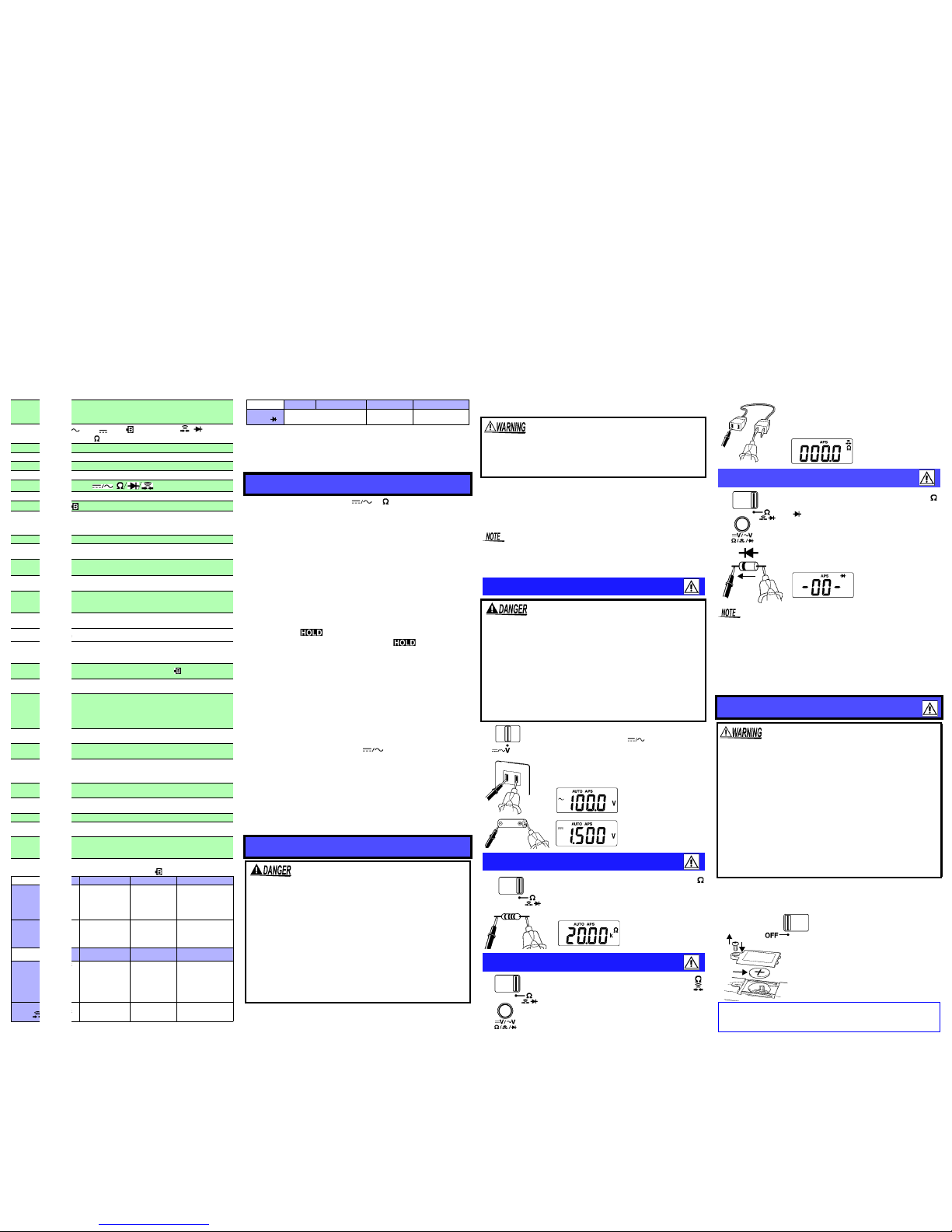
Voltage Measurement
• The maximum input voltage is 600 V DC/ 600 Vrms (sin)
or 3x10
6
V•Hz. Attempting to measure voltage in excess
of the maximum rating could destroy the product and
result in personal injury or death.
• To avoid electrical shock, be careful to avoid shorting
live lines with the test leads.
• For safety, test lead connections must always be made
at the secondary side of a circuit breaker.
• The maximum rated voltage between input terminals
and ground is 600 V DC/AC. Attempting to measure
voltages exceeding 600 V with respect to ground could
damage the product and result in personal injury.
Resistance Measurement
Continuity Check
1.
Move the Function Selector to the V position.
To select DC or AC ( ), use the select
button. (During manual ranging, press the
select button for at least 1 second.)
2. Connect the test leads to the measurement
object, and read the indicated value.
AC Voltage
Measurement
DC Voltage
Measurement
1. Move the Function Selector to the
position.
2. Connect the test leads to the measurement object, and read the indicated value.
1. Move the Function Selector to the
position and press the select button. (
lights up)
(During manual ranging, press the select
button for at least 1 second.)
Diode Check
When the diode is connected in the forward direction, the display shows “-00- ” with a beeping sound.
(When the forward voltage is out of the 0.3 V to 2.0 V range,
the results may be incorrect.)
When connection is reversed, the display shows “----.”
If displays for both directions are the same, the following may
have occurred:
• The diode has malfunctioned.
• The forward voltage of the diode is out of the measurement range.
Replacing the Batteries
• To avoid electric shock when replacing the batteries, first
disconnect the test leads from the object to be measured.
• Before replacing the batteries, make sure that the Function Selector is OFF.
• Be sure to insert them with the correct polarity. Otherwise, poor performance or damage from battery leakage
could result. Replace batteries only with the specified
type. (Coin-shaped lithium battery CR2032)
• After replacing the batteries, replace the cover and
screws before using the product.
• Keep batteries away from children to prevent accidental
swallowing.
• To avoid the possibility of explosion, do not short circuit, disassemble or incinerate batteries.
• Handle and dispose of batteries in accordance with
local regulations.
2. Connect the test leads to the measurement object. When the continuity (threshold: 50±40 or less) is established, the
beeping sounds.
1. Move the Function Selector to the
position and press the select button twice.
( lights up)
(During manual ranging, press the select
button for at least 1 second.)
2. Connect the test leads to the measurement object.
AnodeCathode
Forward
direction
Necessary tool:
• Phillips screwdriver
• Coin-shaped lithium battery (CR2032)
1. Turn OFF the power.
2. Turn the 3246-60 over and use
a Phillips screwdriver to remove
the one retaining screw from
the battery case.
3. Remove the battery case and
mount a new CR2032 battery.
Make sure the polarity is correct.
4. Mount the battery case and
tighten the retaining screw.
Screw
Battery case
2
3
4
CALIFORNIA, USA ONLY
This product contains a CR Coin Lithium Battery which contains Perchlorate Material special handling may apply.
See www.dtsc.ca.gov/hazardouswaste/perchlorate
www.GlobalTestSupply.com
Find Quality Products Online at: sales@GlobalTestSupply.com
 Loading...