

Page 1
Warranty
3244-60
CARD HiTESTER
Instruction Manual
September 2013 Revised edition 4
Printed in Japan
3244L981-04 13-09H
(3244-61)
Warranty malfunctions occurring under conditions of normal use
in conformity with the Instruction Manual and Product Precautionary Markings will be repaired free of charge. This warranty
is valid for a period of three (3) years fro m the date of purchas e.
Please contact the distributor from which you purchased the
product for further information on warranty provisions.
Introduction
Thank you for purchasing the HIOKI Model 3244 -60 CARD HiTESTER. To obtain maximum performance from the instrument,
please read this manual first, and keep it handy for future reference.
Overview
The 3244-60 is a card-shaped digital multimeter designed to
measure DC/AC voltage and resistance, and Continuity check.
1 34
Inspection and Maintenance
Initial Inspection
When you receive the instrument, inspect it carefully to ensure
that no damage occurred during shipping. If damag e is evident,
or if it fails to operate according to the specifications, contact
your dealer or Hioki representative.
Maintenance and Service
• To clean the instrument, wipe it gently with a soft cloth moistened with water or mild detergent. Never use solvents such
as benzene, alcohol, acetone, ether, ketones, thinners or
gasoline, as they can deform and discolor the case.
• If the instrument seems to be malfunctioning, contact your
dealer or Hioki representative.
• Pack the instru ment so that it will not sustain damage during
shipping, and include a desc ription of exi sting da mage. W e c annot accept responsibility for da ma ge i ncu rre d du ri ng s hip pi ng .
• To avoid corrosion from battery leakage, remove the battery
from the instrument if it is to be stored for a long time.
Safety
This manual contains information and warnings essential for
safe operation of the instrument and f or maintaining it in safe operating condition. Before using it, be sure to carefully read the
following safety precautions.
This instrument is designed to comply with IEC
61010 Safety Standards, and has been thoroughly
tested for safety prior to shipment. However, mishandling during use could result in injury or death,
as well as damage to the instrument Using the
instrument in a way not described in this manual
may negate the provided safety fea tures. Be certain
that you understand the instructions and precautions in the manual before use. We disclaim any
responsibility for accidents or injuries not resulting
directly from instrument defects.
Safety Symbols
In the manual, the symbol indicates particularly important
information that the user should read before usin g the in strumen t.
The symbol printed on the instrument indicates that the user
should refer to a corresponding topic in the manual (marked with
the symbol) before using the relevant function.
Indicates a double-insulated device.
Indicates DC (Direct Current).
Indicates AC (Alternating Current).
Symbols for Various Standards
This symbol indicates that the product conforms to safety regulations set out by the EC Directive.
WEEE marking:
This symbol indicates that the electrical and electronic appliance
is put on the EU market after August 13, 2005, and producers of
the Member States are required to display it on the appliance
under Article 11.2 of Directive 2002/96/EC (WEEE).
The following symbols in this manual indicate the relative impo rtance of cautions and warnings.
Indicates that incorrect operation presents an extreme hazard that
could result in serious injury or death to the user.
Indicates that incorrect operat io n p r esents a significant hazard that
could result in serious injury or death to the user.
Indicates that incorrect operation presents a possibility of injury to
the user or damage to the device.
Indicates advisory items related to performance or correct operation of the product.
2
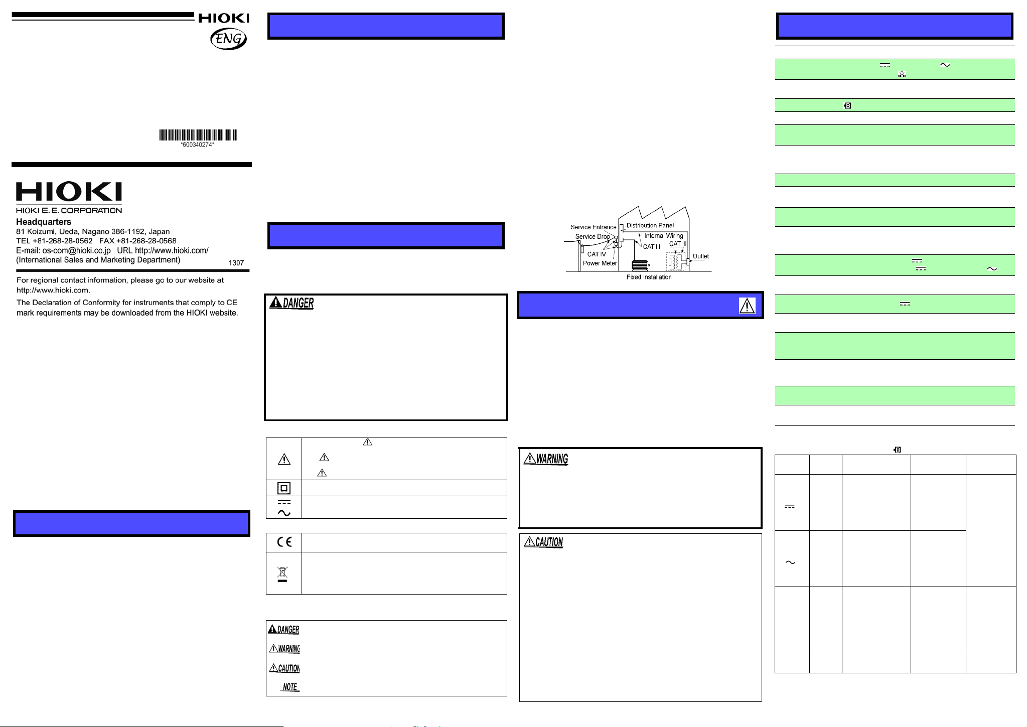
Measurement categories
This product complies with CAT III (300 V), CAT II (600 V) safety
requirements.
To ensure safe operation of measurement products, IEC 61010 establishes safety standards for various electrical environments, categorized as CAT II to CAT IV, and called measurement categories.
CAT II: Primary electrical circuits in equipment connected to an AC
electrical outlet by a power cord (portable tools, household
appliances, etc.)
CAT II covers directly measuring electrical outlet receptacles.
CAT III:Primary electrical circuits of heavy equipment (fixed installa-
tions) connected directly to the distribution panel, and feeders
from the distribution panel to outlets.
CAT IV:The circuit from the service drop to the service entrance, and
to the power meter and primary overcurrent protection device
(distribution panel).
Using a measurement instrumentin an environm ent des ignat ed with a
higher-numbered category than that for which the instrument is rated
could result in a severe accident, and must be carefully avoided.
Use of a measurement instrument that is not CAT-rated in CAT II to
CAT IV measurement applications could result in a severe accident,
and must be carefully avoided.
Usage Notes
Follow these precautions to ensure safe o peration and to obt ain
the full benefits of the various functions.
Preliminary Checks
• Before using the instrument the first time, verify that it oper-
ates normally to ensure that no damage occurre d during st orage or shipping. If you find any damage, contact your dealer
or Hioki representative.
• To prevent an electric shock accident, confirm that the white
portion (insulation layer) inside the cable is not exposed. If a
color inside the cable is exposed, do not use the cable. Using
the instrument in such conditions could cause an electric
shock, so contact your dealer or Hioki representative for repair.
• Do not allow the instrument to g et wet, an d do no t t a ke
measurements with wet hands. The instrument may
be damaged.
• Do not use the instrument where it may be exposed to
corrosive or combustible gases. The instrument may
be damaged or cause an explosion.
• Do not store or use the instrument where it co uld be exposed
to direct sunlight, high temperature or humidity, or condensation. Under such conditions, the instrument may be damaged and insulation may deteriorate so that it no longer
meets specifications.
• This instrument is not designed to be entirely water- or dustproof. Do not use it in an especially dusty environment, nor
where it might be splashed with liquid. This may cause damage.
• Correct measurement may be impossible in the p resenc e of
strong magnetic fields, such as near transformers and highcurrent conductors, or in the presen ce of str ong electromag netic fields such as near radio transmitters.
• To avoid damage to the instrument, protect it from physical
shock when transporting and handling . Be especially ca reful
to avoid physical shock from dropping.
Specification
Measurement method
Function
Display
Battery low display lights
Sampling rate 2.5 times/second
Dimensions and
mass
Accessories
Power supply Battery CR2032 (3 VDC) × 1
Dielectric strength
Maximum input
voltage
Maximum rated
voltage to earth
(50/60 Hz)
Noise rejection ratio
Maximum rated
power
Continuous
operating time
Operating
Environment
Operating
temperature and
humidity
Storage
temperature and
humidity range
Temperature
characteristics
Standards accuracy
Accuracy
Accuracy is guaranteed for 1 year at 23C±5C, 80%RH or less, and no
condensation. Battery low display is off.
Function Range Accuracy *
DCV
[ V]
ACV
[ V]
Continuity 420.0 ±2.0% rdg. ±4 dgt. 3.4 V or less
*1: Input impedance *2: Frequency range *3: Open terminal voltage
*4: Threshold level (buzzer sound) *5: rdg. Displayed value, dgt. Resolution
Double integration
DC voltage ( V), AC voltage( V), Resistance (),
Continuity check( )
3-1/2 digits, LCD, 4199 count max. (except 500 V range)
3 digits, LCD, 549 count max. (500 V range)
Approx. 55W × 109H × 9.5D mm, Approx. 60 g
(Approx. 2.17"W × 4.29"H × 0.37"D, Approx. 2.1 oz).
Instruction Manual, carrying case,
Battery (supplied with this product for monitor),
Sleeves (red and black 1 piece for each)
4.29 kVrms sin (50/60Hz for one minute) between input
and case
500 VDC/ 500 Vrms(sin) or 3×10⁶ V•Hz (DCV/ACV)
When sleeve is installed : CAT III (300 V)
When sleeve is uninstalled: CAT II (600 V)
(Anticipated Transient Overvolta ge: 4000 V)
NMRR:40 dB or more [ V]
CMRR:100 dB or more [ V], 60 dB or more [ V]
15 mVA
Approx.150 hours [ V]
Indoors, Pollution Degree 2, up to 2000 m (6562-ft.)
0 to 40C (32 to 104 F), 80%RH max (no condensation)
-20 to 60°C (-4 to 140 °F),
70%RH max (no condensation)
Measurement accuracy x 0.1 /C (except 23C±5C)
Safety :EN61010
EMC :EN 61326
5
Remarks
420.0 mV ±2.0% rdg. ±4 dgt. 100 M or over
4.200 V ±0.7% rdg. ±4 dgt. Approx. 11 M
42.00 V ±1.3% rdg. ±4 dgt. Approx. 10 M
420.0 V ±1.3% rdg. ±4 dgt. Approx. 10 M
500 V ±1.3% rdg. ±4 dgt. Approx. 10 M
50 to 500 Hz
4.200 V ±2.3% rdg.±8 dgt. Approx. 11 M*
42.00 V ±2.3% rdg.±8 dgt. Approx. 10 M
420.0 V ±2.3% rdg.±8 dgt. Approx. 10 M
500 V ±2.3% rdg.±8 dgt. Approx. 10 M
420.0 ±2.0% rdg. ±4 dgt. 3.4 V or less
4.200 k ±2.0% rdg. ±4 dgt. 0.7 V (typ.)
42.00 k ±2.0% rdg. ±4 dgt. 0.5 V (typ.)
420.0 k ±2.0% rdg. ±4 dgt. 0.5 V (typ.)
4.200 M ±5.0% rdg. ±4 dgt. 0.5 V (typ.)
42.00 M ±10.0% rdg. ±4dgt. 0.5 V (typ.)
*2
50 ±40
*4
Over load
protection
*1
ACrms (sin)
3×10
1
*3
500 V DC/
ACrms (sin)
(one minute)
*3
500 V DC/
or
6
V•Hz
Page 2
Test lead
Red (+) / Black (-)
Connect the test leads to the
object to be measured.
Display
• Measurement value
• Units
• Symbols
• Decimal point
Function switch
• [OFF] Power Off
(
Power is turned ON in
any position other than
OFF.
)
• [ V]DC voltage
• [ V] AC voltage
• []Resistance
• [ ]Continuity check
Test lead be stored here.
Wind wire around case.
Carrying Case
Sleeves
Can be stored here.
Battery
(-)
(+)
Outlet
Leads
Resistor
Leads
Cord
Leads
Rear panel
Battery
CALIFORNIA, USA ONLY
This product contains a CR Coin Lithium Battery which contains
Perchlorate Material - special handling may apply.
See www.dt s c.ca. gov /ha za rdo us was te/p erchlo r at e
Functions
Auto Power Save Function
• This function automatically switches to the power save state
when 30 minutes have elapsed since the last operation.
• The auto power save function is activated automatically
when the power is turned on. To restore from the auto power
save state, turn the function switch to the OFF position once.
To avoid battery depletion, turn the function selector OFF after
use (the Auto Power Save feature consumes a small amount of
current).
To Disable Auto Power Save
1.Move the function switch from the OFF position to the
(continuity check) position before all display segments
appear.
2.While all display segments appear (about one second ), move
the function switch from to . APS
and the Auto Power Save function is disabled. Turning the
function switch momentarily OFF and then back on reactivates Auto Power Save.
OFF is displayed,
Auto-range Function
When measuring a DC voltage [ V], AC voltage [ V], or resistance [], the measurement range is automatically set to the
most appropriate range. Manual range setting is not possible.
Overflow Display
When the input exceeds the measurement range, "OF" is dis-
played.
Names and Functions of Parts
Removable sleeves can be attached to the metal
pins at the ends of the test leads. To prevent a short
circuit accident, be sure to use the test leads with
the sleeves attached when performing measurements in the CAT III measurement category. Remove
the sleeves from the test leads when performing
measurements in the CAT II measurement category.
For details on measurement categories, see "Measurement categories" in the instruction manual.
• The tips of the metal pins are sharp, so take care not to in jure
yourself.
• When performing measurements with the sleeves attached,
be careful to avoid damaging the sleeves.
• If the sleeves are inadvertently removed during measurement, be especially careful in handling the te st leads to avoid
electric shock.
]
Measurement Method
Observe the following precautions to avoid electric
shock.
• Always verify the appropriate setting of the function
selector before connecting the test leads. Disconnect
the test leads from the measurement object before
switching the function selector.
• Never apply voltage to the test leads when the Resistance measurement, Continuity check functions are
selected. Doing so may damage the instrument and
result in personal injury. To avoid electrical accidents,
remove power from the circuit before measuring.
• The maximum input voltage is 500 V DC/ACrms or 3 x
6
10
•V/Hz. Attempting to measure voltage in excess of
the maximum input could destroy the instrument and
result in personal injury or death.
• To avoid electrical shock, be careful to avoid shorting
live lines with the test leads.
• For safety, test lead connections must always be
made at the secondary side of a circuit breaker.
• The maximum rated voltage between input terminals
and ground is CAT III (300 V), CA T II (600 V). Attempting to measure voltages exceeding 450 V with respect
to ground could damage the instru ment and result in
personal injury.
Pre-Operation inspection
To avoid the possibility of electric shock or incorrect measurement, check the following items before using the instrument.
If the operation check reveals any a bnormalities, stop t he check
immediately and do not use the instrument.
To prevent an electric shock accident, confirm that
the white portion (insulation layer) inside the cable is
not exposed. If a color inside the cable is exposed, do
not use the cable. Using the instrument in such conditions could cause an electric shock, so contact
your dealer or Hioki representative for repair.
• For voltage measurement, short the test leads and check that
0 V is displayed.
• For Measuring Resistance or Continu i ty Ch eck, short the test
leads and check that 0 is displayed.
• Measure a test item with a known value (battery, AC supply,
resistor, etc.) to confirm that the known value can be displayed.
Periodic calibration and inspecton is necessary in order to ensure that this instrument operates according to its product specifications.
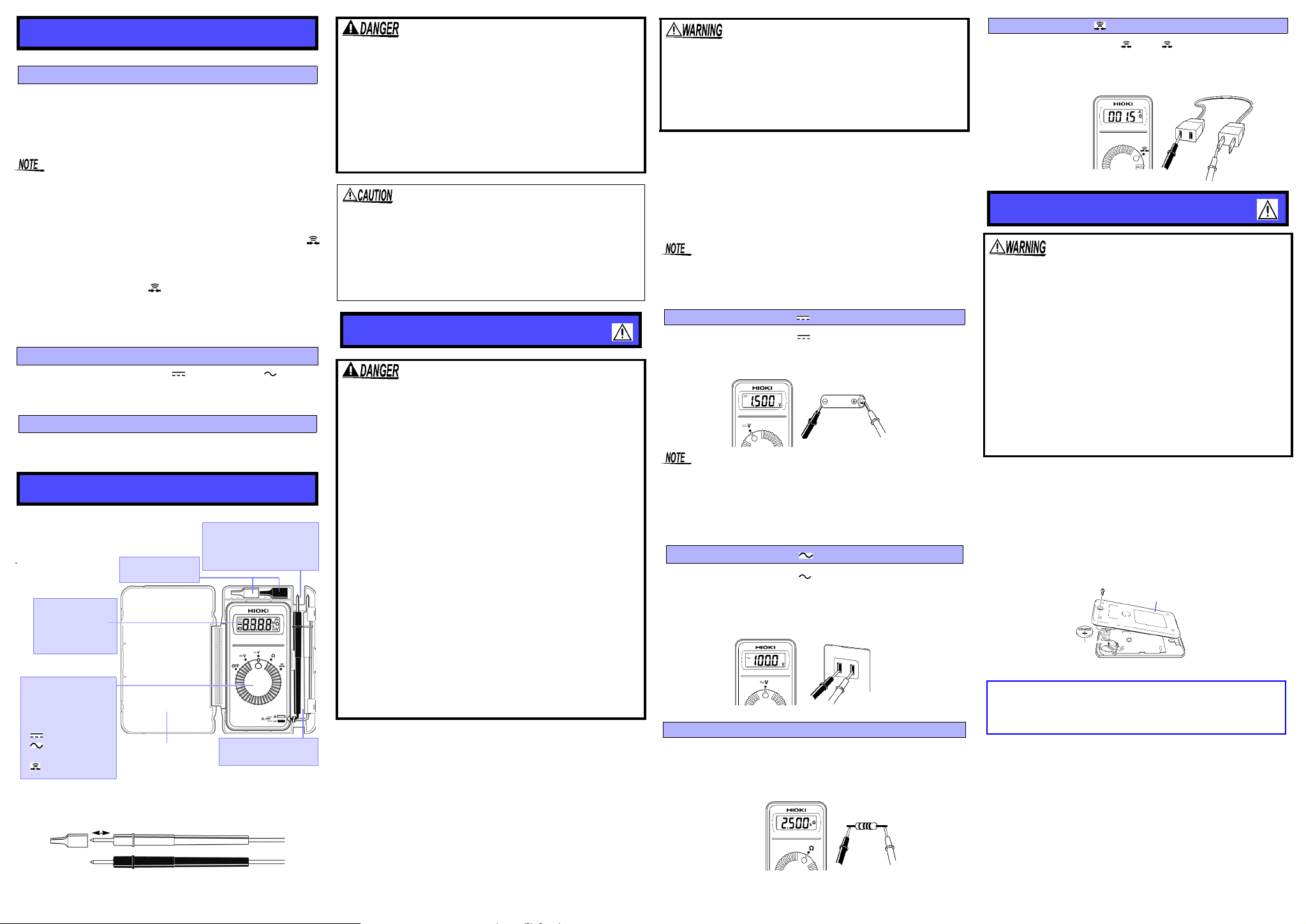
Measuring DC Voltage [ V]
1.Set the function switch to V.
2.Connect the test leads to the object to be measured.
3.Read the display.
• Connecting the leads of negative and positive side oppositely,
"-" is displayed.
• The displayed value may sometimes fluctuate due to induction potential even when no power is supplied. This, however,
is not a malfunction.
Measuring AC Voltage [ V]
1.Set the function switch to V.
2.Connect the test leads to the object to be measured. When
measuring AC voltage, the polarity of leads can be ignored.
3.Read the display.
Measuring Resistance []
1.Set the function switch to .
2.Connect the test leads to the object to be measured.
3.Read the display.
Continuity Check [ ]
1.Set the function switch to . The indication appears.
2.Connect the test leads to the object to be measured.
3.Conductivity is good when the buzzer sounds.
Replacing Battery
• To avoid electric shock when replacing the batteries,
first disconnect the test leads from the object to be
measured. After replacing the batteries, replace the
cover and screws before using the instrument.
• Be sure to insert them with the correct polarity. Otherwise, poor performance or damage from battery leakage could result. Replace batteries only with the
specified type.
• Battery may explode if mistre ate d. Do not short-circuit,
recharge, disassemble or dispose of in fire.
• Handle and dispose of batteries in accordance with
local regulations.
• Keep batteries away from children to prevent accidental swallowing.
1.Remove the test leads from the test item, and power the
instrument off.
2.Remove the instrument from the case, and remove the
screws on the rear panel.
3.Remove the used battery.
4.Being careful about the polarity, insert the new battery
(CR2032) of the specified type.
5.Replace the rear panel and fasten the screws.
Handling the Sleeve
5 78
6
 Loading...