


3237
3237-01
3238
3238-01
3239
3239-01
DIGITAL HiTESTER
Instruction Manual
Oct. 2018 Revised edition 15
3237A981-15 18-10H
EN


Contents
Introduction i
Inspection
Safety Notes
Notes on Use
Chapter Summary
vi
Chapter 1 Overview 1
1.1 Product Overview 1
1.2 Major Features
1.3 Names and Functions of Parts
1.3.1 Front Panel 2
1.3.2 Rear Panel 6
Chapter 2 Installation and Preparation 7
2.1 Power Supply and Ground Connection 7
2.2 Test Lead/Clamp Sensor Connection
i
ii
v
1
2
8
2.3 Power On/Off
2.4 Selection of Power-supply Frequency
10
10
Chapter 3 Measurement Procedure 11
3.1 Voltage Measurement 12
3.1.1 DC Voltage Measurement 12
3.1.2 AC Voltage Measurement 12
3.2 2-Terminal Resistance Measurement 13
3.2.1 Resistance Measurement (2-Terminal) 13
3.2.2 Low-power Resistance Measurement (2-Terminal) 14
3.3 4-Terminal Resistance Measurement 15
3.3.1 Resistance Measurement (4-Terminal, on 3239 only) 15
3.3.2 Low-power Resistance Measurement
(4-Terminal, on 3239 only) 16
3.4 Continuity Test 16
3.5 Diode Test
17
3237A981-15
3.6 Frequency Measurement (3238/39)
18

3.7 Current Measurement (3238/39) 19
3.7.1 DC Current Measurement 19
3.7.2 AC Current Measurement 19
3.8 Clamp Current Measurement 20
3.8.1 DC Clamp Current Measurement
(9277/9278/9279/3284/3285) 21
3.8.2 AC Clamp Current Measurement 22
Chapter 4 Basic Functions 23
4.1 Selection of Measurement Range 23
4.2 Switching of Sampling Period
4.3 Zero Adjust function
4.4 Average function
4.5 Trigger Function
4.5.1 Setup for Trigger mode 26
4.5.2 External Trigger 26
4.5.3 Trigger Delay 27
4.5.4 Trigger System 29
23
24
25
26
Chapter 5 Other Functions 31
5.1 Comparator Function 31
5.2 Comparator Buzzer Sound
5.3 Panel Save Function
5.4 Panel Load Function
5.5 Key Operation Sound
5.6 Key Lock Function
34
35
36
37
38
5.7 Remote Function
5.8 System Reset
5.9 Measurement States and Effective Keys
Chapter 6 External Control Terminal/
External output terminal 43
6.1 Explanation of Signal Wires 44
6.2 Timing Chart
6.3 Internal Circuit Configuration
39
40
42
46
48

Chapter 7 RS-232C Interface 49
7.1 Preparing for Data Transfer 51
7.2 Communication
7.3 Command Code Table
7.3.1 Common Command 62
7.3.2 Specific Command 63
7.4 Command Reference 69
7.4.1 Explanation of Command Reference 69
7.4.2 Common Command Messages 70
7.4.3 Specific Command Messages 75
7.5 Initialized Item List 99
7.6 Notes on RS-232C Interface
7.7 Compatibility with the ADVANTEST Digital
Multimeter
7.8 Sample Program
53
62
99
100
102
Chapter 8 GP-IB Interface(3237-01/3238-01/3239-01) 103
8.1 Preparing for Data Transfer 105
8.2 Communication
8.3 GP-IB Command
8.4 Notes of the GP-IB
107
116
117
Chapter 9 Printer Interface 119
9.1 Setup for Interface 120
9.2 Setup for Printer
9.3 Printer Connection Method
9.4 Sample Prints
121
123
124
Chapter 10 Specifications 125
10.1 General Specifications 125
10.2 Accuracy
10.2.1 Accuracy of the 3237 127
10.2.2 Accuracy of the 3238 133
127
10.2.3 Accuracy of the 3239 140

Chapter 11 Maintenance and Service 147
11.1 A-Terminal Fuse Replacement (3238/39) 147
11.2 Power Supply Fuse Replacement
11.3 Cleaning
11.4 Service
148
149
150
Appendix APPENDIX1

_____________________________________________________________________________________________
p
i
Introduction
Thank you for purchasing the HIOKI "3237, 3238, 3239 DIGITAL
HiTESTER."
To obtain maximum performance from the product, please read this manual
first, and keep it handy for future reference.
Inspection
When you receive the product, inspect it carefully to ensure that no damage
occurred during shipping. In particular, check the accessories, panel
switches, and connectors. If damage is evident, or if it fails to operate
according to the specifications, contact your dealer or Hioki representative.
Accessories
L9170-10 TEST LEAD 1
Instruction Manual 1
Power cord 1
Spare fuse 0.5 A (for 100 V, 120 V), 0.25 A (for 220 V, 240 V)
2 A (for the 3238/39) 1
Before using the product the first time, verify that it operates normally to
ensure that the no damage occurred during storage or shipping. If you find
any damage, contact your dealer or Hioki representative.
Inspection before use
When measuring a dangerous voltage or current, or when a measurement of
high reliability is required, always carry out the following confirmation
before using.
No damage to the power cord, test lead and the produt itself
No inaccurate measurement values are shown when connected to a
measurement target with clear values (non-defective sample, calibrator,
etc.) and under the setting for the test conditions used by the customer
NOTE
______________________________________________________________________________________________
Before using the product, make sure that the insulation on the probes is undamaged
and that no bare conductors are improperly exposed. Using the product in such
conditions could cause an electric shock, so contact your dealer or Hioki
resentative for repair.
re

ii
_____________________________________________________________________________________________
Safety Notes
This instrument is designed to comply with IEC 61010 Safety Standards,
WARNING
and has been thoroughly tested for safety prior to shipment. However,
mishandling during use could result in injury or death, as well as
damage to the instrument. Be certain that you understand the
instructions and precautions in the manual before use. We disclaim any
responsibility for accidents or injuries not resulting directly from
instrument defects.
This manual contains information and warnings essential for safe operation
of the product and for maintaining it in safe operating condition. Before
using the product, be sure to carefully read the following safety notes.
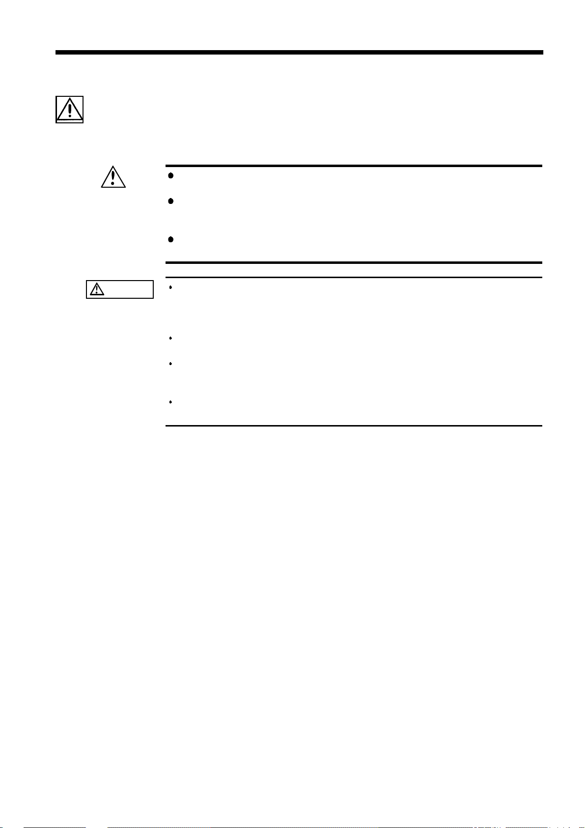
The symbol printed on the product indicates that the user should
refer to a corresponding topic in the manual (marked with the
symbol) before using the relevant function.
In the manual, the symbol indicates particularly important
information that the user should read before using the product.
Indicates that dangerous voltage may be present at this terminal.
Indicates a double-insulated device.
Indicates a fuse.
Indicates AC (Alternating Current).
Indicates DC (Direct Current).
Indicates both DC (Direct Current) and AC (Alternating Current).
Indicates a grounding terminal.
Indicates the ON side of the power switch.
Indicates the OFF side of the power switch.
The following symbols in this manual indicate the relative importance of
cautions and warnings.
Indicates that incorrect operation presents an extreme hazard that
DANGER
could result in serious injury or death to the user.
Indicates that incorrect operation presents a significant hazard that
could result in serious injury or death to the user.
WARNING
CAUTION
NOTE
______________________________________________________________________________________________
Indicates that incorrect operation presents a possibility of injury to
the user or damage to the product.
Advisory items related to performance or correct operation of the
product.

_____________________________________________________________________________________________
iii
Measurement categories
This product complies with CAT II safety requirements.
To ensure safe operation of measurement product, IEC 61010 establishes
safety standards for various electrical environments, categorized as CAT II to
CAT IV, and called measurement categories.
CAT II
CAT III
CAT IV
Primary electrical circuits in equipment connected to
a wall outlet via a power cord (portable tools,
household appliances, etc.)
CAT II covers directly measuring electrical outlet
receptacles.
Primary electrical circuits of heavy equipment (fixed
installations) connected directly to the distribution
panel, and feeders between the distribution panel
and outlets.
The circuit from the service drop to the service
entrance, then to the power meter and to the primary
overcurrent protection device (distribution panel).
Using a measurement product in an environment designated with a highernumbered category than that for which the product is rated could result in
a severe accident, and must be carefully avoided.
Use of a measurement instrument that is not CAT-rated in CAT II to CAT
IV measurement applications could result in a severe accident, and must be
carefully avoided.
______________________________________________________________________________________________

iv
_____________________________________________________________________________________________
Accuracy
The specifications in this manual include figures for "measurement accuracy"
when referring to digital measuring instruments, and for "measurement
tolerance" when referring to analog instruments.
f.s.
rdg.
dgt.
(maximum display or scale value, or length of scale)
Signifies the maximum display (scale) value or the length of the scale
(in cases where the scale consists of unequal increments or where the
maximum value cannot be defined).
In general, this is the range value (the value written on the range
selector or equivalent) currently in use.
(displayed or indicated value)
This signifies the value actually being measured, i.e., the value that is
currently indicated or displayed by the measuring instrument.
(resolution)
Signifies the smallest display unit on a digital measuring instrument,
i.e., the value displayed when the last digit on the digital display is
"1".
______________________________________________________________________________________________
_____________________________________________________________________________________________
v
Notes on Use
In order to ensure safe operation and to obtain maximum performance from
the unit, observe the cautions listed below.
To avoid electric shock, do not allow the product to get wet, and do
WARNING
not use it when your hands are wet.
Do not use the product where it may be exposed to corrosive or
combustible gases. The product may be damaged or cause an
explosion.
To avoid electric shock, be sure to connect the protective ground
terminal to a grounded conductor.
CAUTION
Do not store or use the product where it could be exposed to direct
sunlight, high temperature or humidity, or condensation. Under such
conditions, the product may be damaged and insulation may deteriorate so
that it no longer meets specifications.
This product is not designed to be entirely water- or dust-proof. To avoid
damage, do not use it in a wet or dusty environment.
Do not use the product near a device that generates a strong
electromagnetic field or electrostatic charge, as these may cause
erroneous measurements.
To avoid damage to the product, protect it from vibration or shock during
transport and handling, and be especially careful to avoid dropping.
______________________________________________________________________________________________

vi
_____________________________________________________________________________________________
Chapter Summary
Chapter 1 Overviews
Provides a product overview and gives the names and describes the functions
of the component parts.
Chapter 2 Installation and Preparation
Describes ways to turn on power, connect test leads, and set up the powersupply frequency.
Chapter 3 Measurement Procedure
Describes basic measurements.
Chapter 4 Basic Functions
Describes basic functions such as range setup, sampling setup, and so on.
Chapter 5 Other Functions
Describes other functions, including comparator setup, Load Save function,
and so on.
Chapter 6 External Control Terminal/ External output terminal
Describes external control executed via the external control terminal and
external output terminal.
Chapter 7 RS-232C Interface
Describes external control executed via the RS-232C interface.
Chapter 8 GP-IB Interface
Describes external control executed via the GP-IB interface.
Chapter 9 Printer Interface
Describes output to the optional 9442 PRINTER.
Chapter 10 Specifications
Describes measurement methods designed to achieve maximum performance
from the unit.
Chapter 11 Maintenance and Service
Describes general specifications and measurement ranges.
Appendix
Describes services and options for this unit.
______________________________________________________________________________________________

_____________________________________________________________________________________________
1
Chapter 1
1
2
1.1 Product Overview
In addition to measuring functions for DC voltages, AC voltages, resistances,
DC currents*, AC currents*, and frequencies*, the 3237/38/39 Digital High
Tester comes with a comparator function that is especially useful for line
use. The GP-IB interface (3237-01/3238-01/3239-01), RS-232C interface,
and the units comparator output permits use of the unit across a wide range
of applications, such as parts selection and data acquisition.
*: On the 3238/39.
1.2 Major Features
Overview
3
4
5
6
7
8
9
(1) High-speed measurement and fast OK/NG determination
Allows reduced tact time for the line in high-speed measurements and fast
OK/NG determinations. Thirty different setup conditions for the main unit
can be saved, including comparator conditions. This makes it possible to
determine OK or NG for many sample types being measured with a single
unit.
(2) Low-power resistance measurement
The unit enables low-power resistance measurement, with low measurement
current and open voltage, to minimize the potential for degraded sample
characteristics.
(3) A versatile array of interfaces
The unit comes equipped with a GP-IB interface (3237-01/3238-01/3239-01),
RS-232C interface, external output terminal, and external control terminal.
Through these interfaces, data can be exchanged with a computer or
sequencer.
10
11
12
13
14
A
______________________________________________________________________________________________
1.2 Major Features

2
_____________________________________________________________________________________________
1.3 Names and Functions of Parts
1.3.1 Front Panel
Ω
V
CLAMP
terminal
COM
terminal
3237
LED
Display
Power switch
Ω
V
CLAMP
terminal
COM
terminal
A-terminal
SENSE terminal
Ω
V
CLAMP
terminal
COM
terminal
Operation keys
3238
LED
Display
Power swtich
Operation keys
3239
LED
Display
A-terminal
Operation keys
______________________________________________________________________________________________
1.3 Names and Functions of Parts
Power swtich
_____________________________________________________________________________________________
3
Operation keys
V
V
Ω
LPΩ
SHIFT
+
Hz
A
A
COMP
M.TRIG
LOAD
SAVE
LOCA L
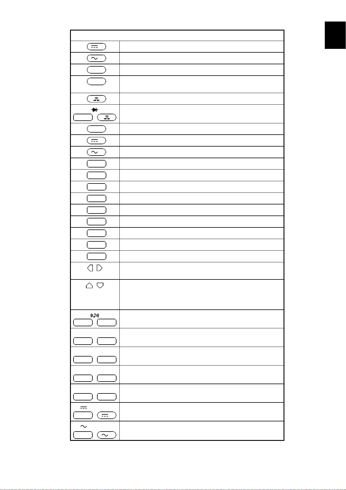
Selects the DC voltage measurement function.
Selects the AC voltage measurement function.
Selects the 2-terminal resistance measurement function.
Selects the low-power 2-terminal resistance measurement
function.
Selects the continuity test function.
Selects the diode test function.
Selects the frequency measurement function. (3238/39)
Selects the DC current measurement function. (3238/39)
Selects the AC current measurement function. (3238/39)
Turns the comparator ON or OFF.
Applies a manual trigger.
Recalls saved information.
Saves the current status.
Clears the remote status.
1
2
3
4
5
6
7
SMPL
SHIFT
ENT
AUTO
SHIFT+COMP
INT.TRIG
SHIFT+M.TRIG
0ADJ
SHIFT+LOAD
LOCK
SHIFT+LOCA L
AVE
SHIFT+SMPL
CLAMP
SHIFT
V
+
Switches the sampling period.
Pressed before shift operation.
Confirms a setting.
Selects Auto Range.
Used to move the cursor indicated by flashing numbers or
characters on a setup screen.
Used to increment or decrement the currently flashing value.
These buttons are also used to edit character strings in
various setup screens, and to switch ranges when a
measurement is performed.
Turns the comparator buzzer ON or OFF.
Applies an internal trigger.
Subtracts the offset of a measurement value.
Locks the keys.
Sets the mean of the measurement values.
Selects the DC current measurement function that uses the
clamp sensor.
8
9
10
11
12
13
14
CLAMP
SHIFT
+
______________________________________________________________________________________________
Selects the AC current measurement function that uses the
clamp sensor.
V
1.3 Names and Functions of Parts
A

4
_____________________________________________________________________________________________
Operation keys
4WΩ
SHIFT
+
4WΩ
SHIFT
+
MENU
SHIFT+ENT
Terminals
COM
Ω
V
CLAMP
A
SENSE
Switch
POWER
Ω
LPΩ
Selects the 4-terminal resistance measurement function.
(3239 only)
Selects the low-power 4-terminal resistance measurement
function. (3239 only)
Displays the menu screen for selection of the clamp sensor,
interfaces, power-supply frequency, etc.
The test lead (black) is connected here for various
measurements.
The test lead (red) is connected here to measure voltages,
resistances, frequencies, diodes, or clamp currents, or to
conduct a continuity test.
The test lead (red) is connected here to measure currents.
(3238/39)
The test lead (SENSE) is connected here to measure
resistance (4-terminal resistance measurement). (3239)
Turns the power ON ( )orOFF( ).
______________________________________________________________________________________________
1.3 Names and Functions of Parts
_____________________________________________________________________________________________
5
1
2
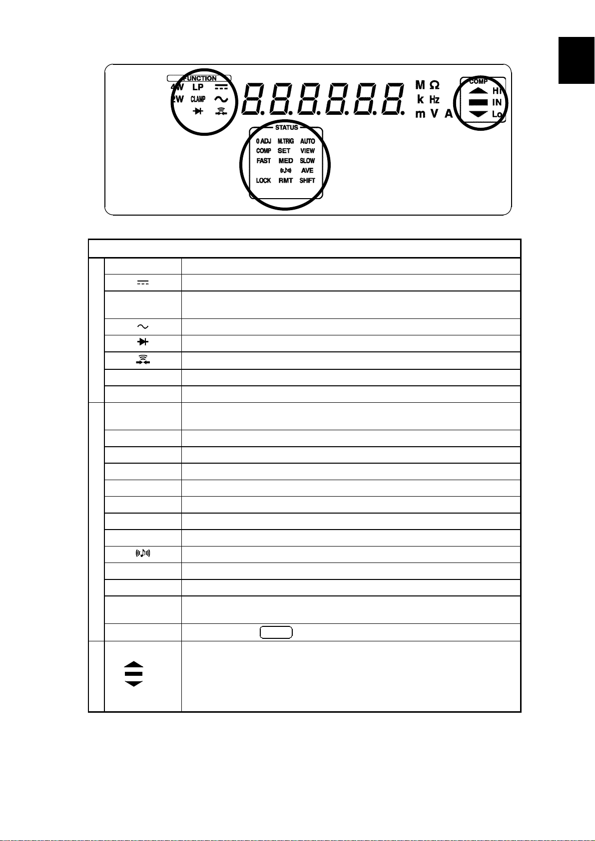
FUNCTION
LED display
LP
CLAMP
FUNCTION
4W
2W
0ADJ
M.TRIG
AUTO
COMP
SET
FAST
MED
STATUS
SLOW
AVE
LOCK
RMT
SHIFT
COMP
Hi
IN
Lo
COMP
STATUS
Lights up when a low-power resistance measurement is performed.
Lights up when a DC measurement is performed.
Lights up when a current measurement is performed using the clamp
sensor.
Lights up when a AC measurement is performed.
Lights up when a diode test is conducted.
Lights up when a continuity test is conducted.
Lights up when a 4-terminal resistance measurement is performed. (3239)
Lights up when a 2-terminal resistance measurement is performed. (3239)
Lights up when a measurement is in progress with the Zero Adjust
function activated.
Lights up when Manual Trigger is selected.
Lights up when Auto Range is selected.
Lights up when the comparator is in use.
Lights up together with COMP when a comparator threshold is set.
Lights up when FAST is selected for the sampling period.
Lights up when MEDIUM is selected for the sampling period.
Lights up when SLOW is selected for the sampling period.
Lights up when the comparator buzzer is turned ON.
Lights up when the Average function is in use.
Lights up when the Key Lock is active.
Lights up when remote control is underway through the RS-232C or GP-
IB interface.
Lights up when
Displays the comparator result.
: Lights up if the measurement value exceeds the upper-limit value.
Hi
: Lights up if the measurement value remains between the upper-
IN
limit and lower-limit values.
: Lights up if the measurement value is smaller than the lower-limit
Lo
value.
SHIFT
is pressed.
3
4
5
6
7
8
9
10
11
12
13
14
______________________________________________________________________________________________
1.3 Names and Functions of Parts
A
6
_____________________________________________________________________________________________
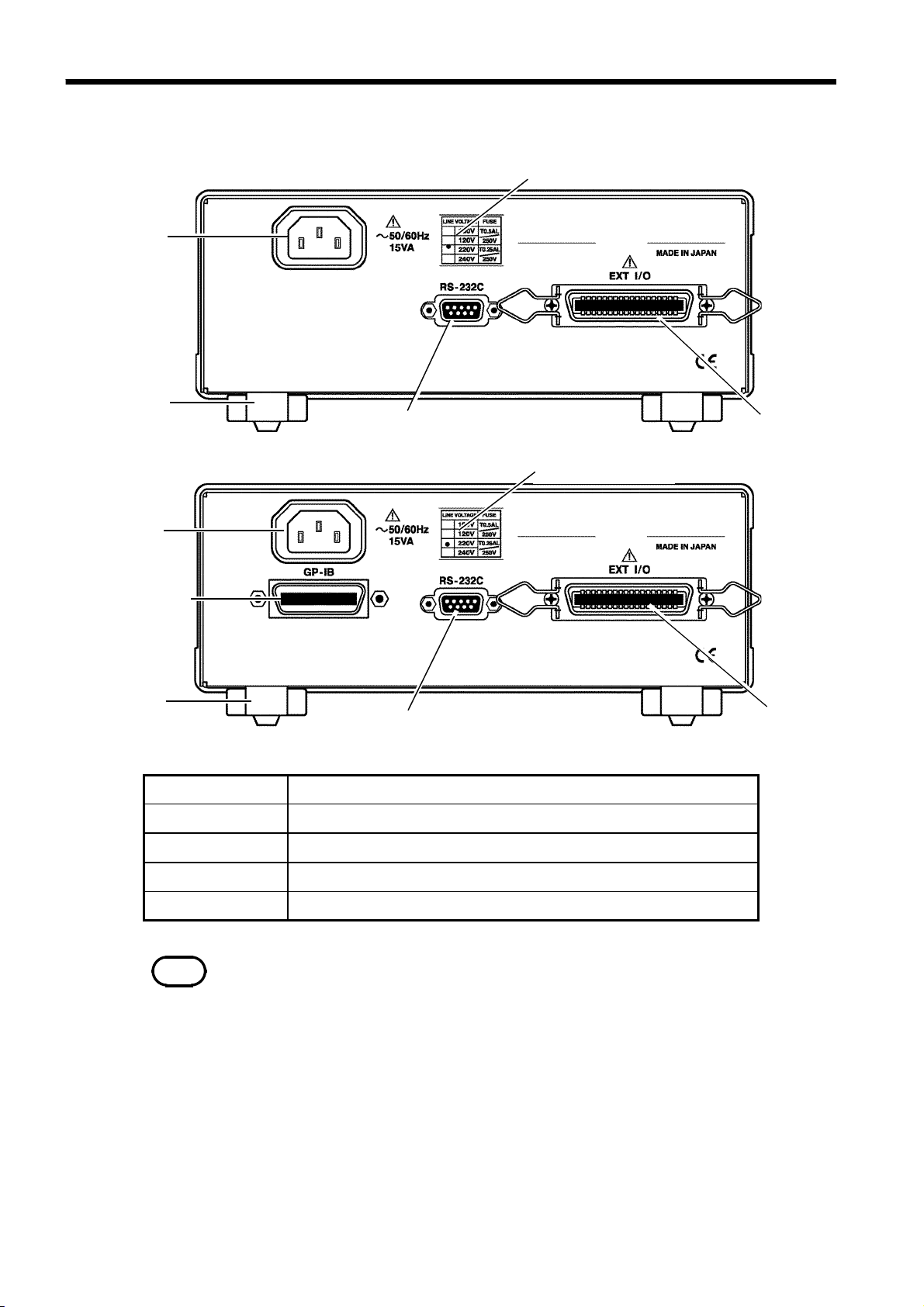
1.3.2 Rear Panel
Power/fuse ratings
3237
Inlet
Stand
RS-232C interface
Power/fuse ratings
3238
3239
External I/O
Inlet
GP-IB interface
Stande
GP-IB interface
RS-232C interface
Power/fuse ratings
NOTE
Inlet
ExternalI/O
Be sure not to bear down too hard on the top of the product when it is tilted
upwards. Doing so may damage the stand.
RS-232C interface
The power cord is connected here.
The GP-IB interface is connected here.
The RS-232C interface is connected here.
This is an external output terminal/external control terminal.
Indicates the power ratings and the fuse currently in use.
3237-01
3238-01
3239-01
External I/O
______________________________________________________________________________________________
1.3 Names and Functions of Parts

_____________________________________________________________________________________________
7
Chapter 2
1
2
Installation and Preparation
2.1 Power Supply and Ground Connection
Before turning the product on, make sure the source voltage matches
WARNING
that indicated on the product's power connector. Connection to an
improper supply voltage may damage the product and present an
electrical hazard.
To avoid electrical accidents and to maintain the safety specifications
of this instrument, connect the power cord provided only to a 3contact (two-conductor + ground) outlet.
3
4
5
6
7
8
1
. Confirm the power switch is OFF.
2
. Make sure the source voltage matches that indicated on the product's
power connector and connect the power cord supplied to AC inlet on the
rear panel.
3
. Plug in the power cord. Insert the plug directly into the outlet.
9
10
11
12
13
14
______________________________________________________________________________________________
2.1 Power Supply and Ground Connection
A

8
_____________________________________________________________________________________________
2.2 Test Lead/Clamp Sensor Connection
The terminals do not have sufficient spatial isolation. To avoid
WARNING
electrocution, observe the following precautions.
Connect test leads to the terminals only after shutting off the line
power.
Note that hazardous voltage may be present at the V
CLAMP terminal when using the A-terminal. Be careful to avoid
touching the V
Note that hazardous voltage may be present at the A-terminal when
using the V
careful to avoid touching the A-terminal.
When connecting the clamp-on sensor, should the metallic part of the
sensor, exposed while the clamp is open, touch the two wires of the
line, or if the sensor is used on a bare conductor, may result in a short
circuit or electrocution.
Ω
Ω
CLAMP terminal and SENSE terminal.
CLAMP terminal and SENSE terminal. Be
Ω
CAUTION
NOTE
CAUTION
Although CAT III, CAT IV are stated on the L9170-10 TEST LEAD, the
DIGITAL HiTESTER is only compatible with CAT I and CAT II.
To avoid electrocution, do not measure the lines of CAT III or CAT IV.
To prevent an electric shock accident, confirm that the white or red portion
(insulation layer) inside the cable is not exposed. If a color inside the cable is
exposed, do not use the cable.
Removable sleeves are attached to the metal pins at the ends of the test leads. The
test leads can also be used with the sleeves removed.
Removing and attaching the sleeves
The tips of the metal pins are sharp, so take care not to injure yourself.
Removing the sleeves
Gently hold the bottom of the sleeves and pull the sleeves off.
Safely store the removed sleeves so as not to lose them.
Attaching the sleeves
Insert the metal pins of the test leads into the holes of the sleeves, and firmly
push them all the way in.
______________________________________________________________________________________________
2.2 Test Lead/Clamp Sensor Connection

_____________________________________________________________________________________________
9
3238
(1) Voltage measurement/ 2-terminal resistance measurement/
continuity test/ diode test/ frequency measurement
32393237/38
1
. Disconnect the L9170-10 TEST LEAD
from the sample being measured.
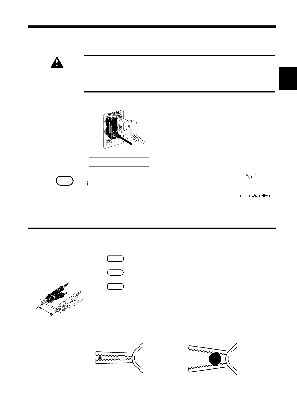
2
. Connect the black lead to the COM
terminal and the red lead to
the V Ω CLAMP terminal.
Black
Black
Red
Red
L9170-10 TEST LEAD
(2) Current measurement
L9170-10 TEST LEAD
Black
3239
Black
Red
Red
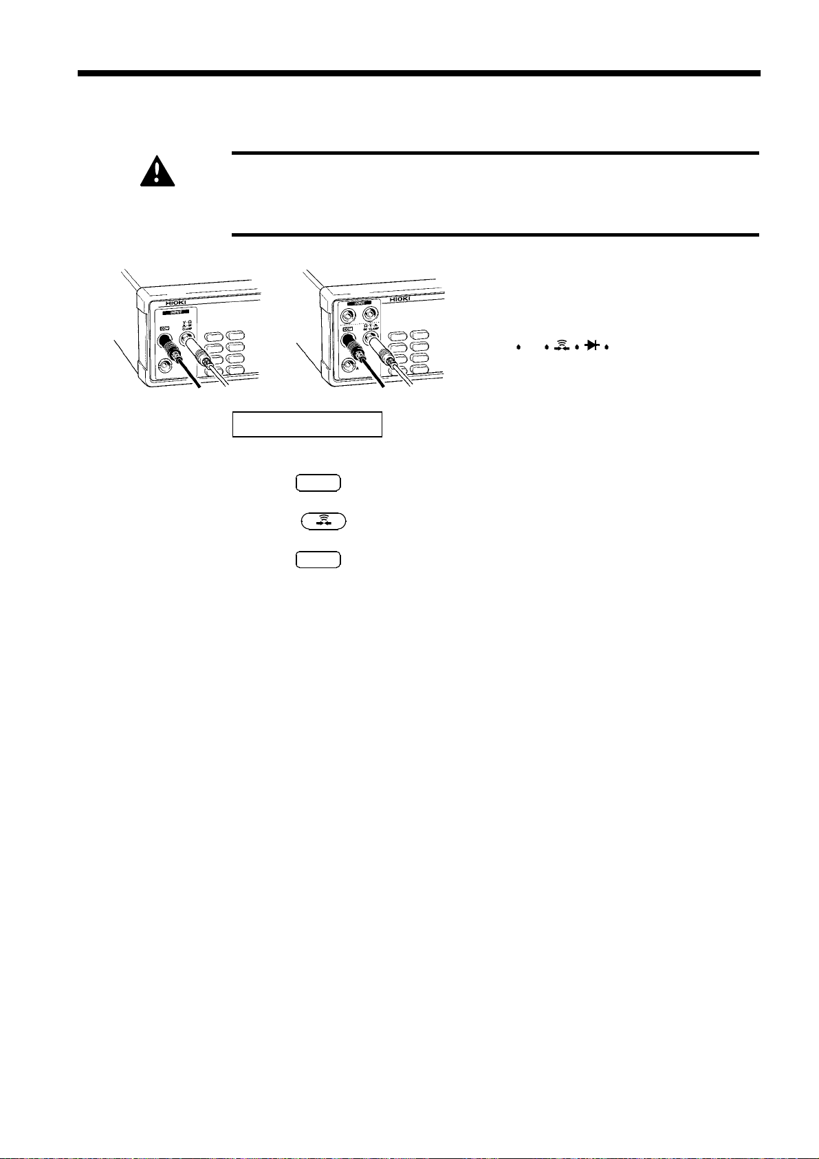
1
. Disconnect the L9170-10 TEST LEAD
from the sample being measured.
2
. Connect the black lead to the COM
terminal and the red lead to the Aterminal.
1
2
3
4
5
6
7
8
3237/38
Black
(3) Clamp current measurement
3239
Red
Clamp sensor connector
(4) 4-terminal resistance measurement
3239
Black
L2107 CLIP TYPE LEAD
Black
Red
Red
1
. Disconnect the clamp sensor from the
sample being measured.
2
. Connect the black lead to the COM
terminal and the red lead to
the V Ω CLAMP terminal.
1
. Disconnect the clamp sensor from the
sample being measured.
2
. Connect 4-terminal test leads like
those of the L2107 as shown in the
drawing. Align the triangular mark on
the red lead with the red triangular
mark on the chassis, and the triangular
mark on the black lead with the black
triangular mark on the chassis.
9
10
11
12
13
14
A
______________________________________________________________________________________________
2.2 Test Lead/Clamp Sensor Connection

10
y
_____________________________________________________________________________________________
2.3 Power On/Off
(1) How to turn on power
Turn on ( ) the power switch on the front panel.
All the LEDs on the front panel will light to indicate the model, software
version and power-supply frequency of the unit. The unit readies itself for
measurement.
After power is turned on, the unit is set to the same measurement conditions
in effect when the unit was switched off.
NOTE
Allow the unit to warm up for 60 minutes before starting measurement.
(2) How to turn off power
Turn off ( ) the power switch on the front panel.
The measurement conditions will be saved.
NOTE
As long as the unit is in normal measurement or comparator execution modes, the
various conditions will be saved even in the event of a power blackout.
2.4 Selection of Power-supply Frequency
1
.Press
2
. Pressing
3
.Press to display the power-supply frequency setup screen.
SHIFT
."SHIFT" lights up on the display.
ENT
opens the menu screen for entering various settings.
4
. Pressing causes the frequency power-supply currently set to flash.
"50": 50 Hz
"60": 60 Hz
5
.Press to select a power-supply frequency.
6
. Pressing
7
.Press
NOTE
______________________________________________________________________________________________
2.4 Selection of Power-supply Frequency
To properly suppress noise, this product must be set to match the power supply
frequency. Before using the product, make sure the power supply frequency selector
is set correctl
ENT
causes "Fr" to flash.
ENT
again to define your selection.
, to avoid erroneous readings.

_____________________________________________________________________________________________
11
Chapter 3
1
2
DANGER
Measurement Procedure
Observe the following precautions to avoid electric shock.
Always verify the appropriate setting of the measuring function before
connecting the test leads.
Disconnect the test leads from the measurement object before
changing the measuring function.
Clamp sensor/ Clamp-on probe/ Test leads should only be connected
to the seconda ry side of a breaker, so the breaker can prevent an
accident if a short circuit occurs. Connections should never be made
to the primary side of a breaker, because unrestricted current flow
could cause a serious accident if a short circuit occurs.
Do not measure an input in excess of the maximum rated working
voltage and current, as the resulting heat buildup may damage the
product or cause a short-circuit accident.
The maximum rated voltage to ground of the V
terminal is 600 VAC/DC (CAT II) or 1000 VAC/DC. (Cannot be used with
CAT II, CAT III and CAT IV. Can be used when not directly connected
to main power sources such as a battery or solar power, and transient
overvoltage is below 2.5 kV.) . Do not apply any voltage to this
terminal exceeding these ratings.
The maximum rated voltage to ground of the COM terminal is 300
VAC/DC (CAT II) or 500 VAC/DC (Cannot be used with CAT II, CAT III
and CAT IV. Can be used when not directly connected to main power
sources such as a battery or solar power, and transient overvoltage is
below 2.5 kV.). Do not apply any voltage to this terminal exceeding
these ratings.
The maximum rated voltage to ground of the A-terminal is 300 VAC/DC
(CA T II) or 500 VAC/DC (Cannot be used with CAT II, CAT III and CA T IV.
Can be used when not directly connected to main power sources such
as a battery or solar power, and transient overvoltage is below 2.5 kV.).
Do not apply any voltage to this terminal exceeding these ratings.
The maximum rated voltage to ground of the SENSE terminal is 300
VAC/DC (CAT II) or 500 VAC/DC (Cannot be used with CAT II, CAT III and
CA T IV. Can be used when not directly connected to main power sources
such as a battery or solar power, and transient overvoltage is below 2.5
kV.). Do not apply any voltage to this terminal exceeding these ratings.
To avoid electrical shock, be careful to avoid shorting live lines with
the test leads.
If the test leads are open-circuited, live high voltage lines cannot be
detected. After connecting the test leads, perform continuity tests to
confirm that the test leads are not open-circuited.
(See "3.4 Continuity Test".)
Ω
CLAMP
3
4
5
6
7
8
9
10
11
12
13
14
A
______________________________________________________________________________________________

12
_____________________________________________________________________________________________
3.1 Voltage Measurement
The maximum rated working voltage is 1000 VDC/700 VrmsAC (107V
DANGER
Black
Hz). Attempting to measure voltage in excess of the maximum rating
could destroy the product and result in personal injury or death.
32393237/38
Red
L9170-10 TEST LEAD
Black
3.1.1 DC Voltage Measurement
1
. Make sure that "SHIFT" does not light on the display.
2
.Press
V
.
・
Check to make sure that the black lead of
the L9170-10 TEST LEAD is connected
to the COM terminal and the red lead to
the V Ω CLAMP terminal.
Red
3
.Press to select a range. Or press
(See 4.1 Selection of Measurement Range.)
4
.Press
SMPL
to select a sampling period.
(See 4.2 Switching of Sampling Period.)
5
. Connect the test lead to the sample being measured and read the value.
3.1.2 AC Voltage Measurement
1
. Make sure that "SHIFT" does not light on the display.
2
.Press
3
.Press to select a range. Or press
(See 4.1 Selection of Measurement Range.)
N
L
4
.Press
(See 4.2 Switching of Sampling Period.)
V
SMPL
.
to select a sampling period.
AUTO
AUTO
to select Auto Range.
to select Auto Range.
5
. Connect the test lead to the sample being measured and read the value.
______________________________________________________________________________________________
3.1 Voltage Measurement

_____________________________________________________________________________________________
13
3.2 2-Terminal Resistance Measurement
1
DANGER
Black
NOTE
Never apply voltage to test leads and SENSE terminal when the
Resistance, Low-power resistance or Continuity Check are selected.
Doing so may damage the product and result in personal injury.
To avoid electrical accidents, remove power from the circuit before
measuring.
32393237/38
Red
L9170-10 TEST LEAD
When measuring high resistance, there are cases in which an overload (“OF
displayed) occurs owing to external noise. Do not use the unit near fluorescent light
or power line.
When external noise is high, please shield the red lead (connected to the V
CLAMP terminal) and the sample to be measured. Connect the outer shield cover to the
COM terminal. (Or use a shielded line, such as the 9326 CONNECTION CORD.)
In case of using a dial resistor, connect the GUARD terminal to the COM terminal
of the unit.
Black
Red
Check to make sure that the black lead of
the L9170-10 TEST LEAD is connected
to the COM terminal and the red lead to
the V Ω CLAMP terminal.
”
Ω
2
3
4
5
6
7
8
9
3.2.1 Resistance Measurement (2-Terminal)
1
. Make sure that "SHIFT" does not light on the display.
2
.Press
3
.Press to select a range. Or press
(See 4.1 Selection of Measurement Range.)
4
.Press
(See 4.2 Switching of Sampling Period.)
5
. Performs zero-ajust for the 3237/38/39.
(See 4.3 Zero Ajust Function.)
6
. Connect the test lead to the sample being measured and read the value.
Ω
."2W" lights up on the display. (3239)
SMPL
to select a sampling period.
AUTO
to select Auto Range.
10
11
12
13
14
A
______________________________________________________________________________________________
3.2 2-Terminal Resistance Measurement

14
_____________________________________________________________________________________________
3.2.2 Low-power Resistance Measurement (2-Terminal)
1
. Make sure that "SHIFT" does not light on the display.
2
.Press
3
.Press to select a range. Or press
(See 4.1 Selection of Measurement Range.)
4
.Press
(See 4.2 Switching of Sampling Period.)
5
. Performs zero-ajust for the 3237/38/39.
(See 4.3 Zero Ajust Function.)
6
. Connect the test lead to the sample being measured and read the value.
LPΩ
."2W"(3239) and "LP" lights up on the display.
SMPL
AUTO
to select a sampling period.
to select Auto Range.
______________________________________________________________________________________________
3.2 2-Terminal Resistance Measurement
_____________________________________________________________________________________________
(
15
3.3 4-Terminal Resistance Measurement
1
DANGER
NOTE
Never apply voltage to test leads and SENSE terminal when the
Resistance, Low-power resistance or Continuity Check are selected.
Doing so may damage the product and result in personal injury.
To avoid electrical accidents, remove power from the circuit before
measuring.
3239
The four terminals of the L2107 CLIP TYPE
LEAD
Verify that all four terminals (SOURCE+,
SOURCE-, SENSE+, and SENSE-) are
connected. Also verify that the triangular mark
Black
L2107 CLIP TYPE LEAD
When measuring high resistance, there are cases in which an overload (“OF
displayed) occurs owing to external noise. Do not use the unit near fluorescent light
or power line.
When external noise is high, please shield the red lead (connected to the V
CLAMP terminal) and the sample to be measured. Connect the outer shield cover to the
COM terminal. (Or use a shielded line, such as the 9326 CONNECTI ON CORD.) In case
of using a dial resistor, connect the GUARD terminal to the COM terminal of the unit.
Red
on the red lead is aligned with the red
triangular mark on the chassis, and that the
triangular mark on the black lead is aligned
with the black triangular mark on the chassis.
”
Ω
2
3
4
5
6
7
8
3.3.1 Resistance Measurement (4-Terminal, on 3239 only)
SHIFT
."SHIFT" lights up on the display.
Ω
."4W" lights up on the display.
SMPL
to select a sampling period.
Rx
1
.Press
2
.Press
3
.Press
(See 4.2 Switching of Sampling Period.)
4
. Performs zero-ajust for the 3237/38/39.
(See 4.3 Zero Ajust Function.)
5
. Connect the test lead to the sample being measured and read the value.
9
10
11
12
13
14
A
When clipping a thin line
Clipthe line at the tip,
______________________________________________________________________________________________
When clipping a thick line
Clipthe line at the deep,non-
3.3 4-Terminal Resistance Measurement

16
_____________________________________________________________________________________________
3.3.2 Low-power Resistance Measurement
(4-Terminal, on 3239 only)
1
.Press
2
.Press
3
.Press
(See 4.2 Switching of Sampling Period.)
4
. Performs zero-ajust for the 3237/38/39.
(See 4.3 Zero Ajust Function.)
5
. Connect the test lead to the sample being measured and read the value.
NOTE
When measurement is performed using the low-power resistance measurement
function or continuity test function, the measurement values may not be stable,
because the measurement current in this measurement mode is lower than for
normal resistance measurement.
3.4 Continuity Test
SHIFT
LPΩ
SMPL
SHIFT
."
" lights up on the display.
."4W"and"LP" lights up on the display.
to select a sampling period.
NOTE
1
. Make sure that "SHIFT" does not light on the display.
2
.Press .
3
. Connect the test lead to the sample being measured.
The buzzer will beep if the resistance value is below 50 ohms.
When measurement is performed using the low-power resistance measurement
function or continuity test function, the measurement values may not be stable,
because the measurement current in this measurement mode is lower than for
normal resistance measurement.
The resistance measurement and low-power resistance measurement will display
values that include the resistance value of the test lead. Use the Zero-Adjust
function to exclude this resistance value.
______________________________________________________________________________________________
3.4 Continuity Test
_____________________________________________________________________________________________
17
3.5 Diode Test
Never apply voltage to test leads when the Diode test is selected. Doing
DANGER
so may damage the product and result in personal injury.
To avoid electrical accidents, remove power from the circuit before
measuring.
32393237/38
Check to make sure that the black lead of
the L9170-10 TEST LEAD is connected
to the COM terminal and the red lead to
the V Ω CLAMP terminal.
Black
Red
L9170-10 TEST LEAD
1
.Press
2
.Press .
3
.Press
SHIFT
."SHIFT" lights up on the display.
SMPL
to select a sampling period.
Black
Red
(See 4.2 Switching of Sampling Period.)
4
. Connect the test lead to the sample being measured and read the value.
A normal silicon diode indicates a forward voltage of 0.4 to 0.7 V. In the
reverse direction, "OF" will light.
______________________________________________________________________________________________
3.5 Diode Test

18
_____________________________________________________________________________________________
3.6 Frequency Measurement (3238/39)
The maximum rated working voltage is 600 VDC/700 VrmsAC (107V・Hz).
DANGER
Attempting to measure voltage in excess of the maximum rating could
destroy the product and result in personal injury or death.
3238
Black
NOTE
3239
Check to make sure that the black lead of
the L9170-10 TEST LEAD is connected
to the COM terminal and the red lead to
the V Ω CLAMP terminal.
Red
L9170-10 TEST LEAD
1
.Press
2
.Press to select an attenuator range.
3
.Press
Hz
SMPL
Black
.
to select a sampling period.
Red
(See 4.2 Switching of Sampling Period.)
4
. Connect the test lead to the sample being measured and read the value.
Press to set a range for the attenuator circuit (voltage divider circuit).
Input sensitivity is approximately 10% of the selected attenuator range. Check
the signal level with the
Example: The frequency of a 10 V signal can be measured in the attenuator range
of 2 V or 20 V, but not in the attenuator range of 200 V or 700 V.
V function before measuring the frequency.
______________________________________________________________________________________________
3.6 Frequency Measurement (3238/39)

_____________________________________________________________________________________________
19
3.7 Current Measurement (3238/39)
The maximum rated working current is 2 ADC/AC. Attempting to input
DANGER
current in excess of the maximum rating could destroy the product
and result in personal injury or death.
Never apply voltage to A-terminal. Doing so may damage the product
and result in personal injury. To avoid electrical accidents, remove
power from the circuit before measuring.
3238
Red
Black
L9170-10 TEST LEAD
3239
Black
Red
3.7.1 DC Current Measurement
1
.Press
2
.Press to select a range. Or press
(See 4.1 Selection of Measurement Range.)
3
.Press
(See 4.2 Switching of Sampling Period.)
A
SMPL
.
to select a sampling period.
Check to make sure that the black lead of
the L9170-10 TEST LEAD is connected
to the COM terminal and the red lead to
the A-terminal.
AUTO
to select Auto Range.
4
. Connect the test lead to the sample being measured and read the value.
NOTE
After measuring large current, the terminal may become hot, producing
thermoelectric power that may cause incorrect measurement results.
Therefore, after measuring large current, wait a moment before measuring
again.
3.7.2 AC Current Measurement
1
.Press
2
.Press to select a range. Or press
(See 4.1 Selection of Measurement Range.)
3
.Press
(See 4.2 Switching of Sampling Period.)
4
. Connect the test lead to the sample being measured and read the value.
______________________________________________________________________________________________
A
SMPL
.
to select a sampling period.
AUTO
to select Auto Range.
3.7 Current Measurement (3238/39)

20
_____________________________________________________________________________________________
3.8 Clamp Current Measurement
To avoid short circuits and potentially life-threatening hazards, never
DANGER
attach the clamp to a circuit that operates at more than the maximum
rated voltage, or over bare conductors.
Before using the clamp sensor, carefully read the supplied instruction
manual.
NOTE
3237, 3238
The Auto Range function cannot be used in clamp current measurement.
3239
Black
Red
Connect the Clamp sensor connector to
the 9704 CONVERSION ADAPTER.
9704
CONVERSION
ADAPTER
Connect the 9704 black COM terminal to
the COM terminal of the main unit and
the 9704 red terminal to the V Ω
CLAMP terminal of the main unit.
Clamp sensor connector
Selection of the clamp sensor
1
.Press
2
. Pressing
3
.Press to display the clamp sensor setup screen.
SHIFT
."SHIFT" lights up on the display.
ENT
displays the menu screen.
4
. Pressing causes the currently selected clamp sensor model to flash.
5
.Press to select a clamp sensor.
6
. Pressing
7
. Another press to
NOTE
______________________________________________________________________________________________
3.8 Clamp Current Measurement
If you plan to use the 9081 External Shunt Resistor, Class 1.0, specify 9278 on
the clamp sensor selection screen. The value can be read directly as a current
value.
The available clamp sensors as of Dec. 1, 2008, are 90 10-50/9018-50/9132-50.
Accuracy cannot be guaranteed if you use clamp sensor unit models
9270/9271/9272/9277/9278/9279/3283/3284/3285.
ENT
causes "CL" to flash.
ENT
confirms your selection.

_____________________________________________________________________________________________
21
3.8.1 DC Clamp Current Measurement
1
.Press
2
.Press
3
.Press to select a clamp sensor range.
4
.Press
(See 4.2 Switching of Sampling Period.)
5
. Clip the clamp around one of wires of the circuit to be measured and read
the value.
Source side
SHIFT
."SHIFT" lights up on the display.
V
.
SMPL
to select a sampling period.
Load side
(9277/9278/9279/3284/3285)
Corresponds the current
direction indication to
the direction of current
flow.
NOTE
The DC clamp current measurement function cannot be used if a clamp sensor
other than 9277/9278/9279/3284/3285 is selected.
Auto Range cannot be used.
______________________________________________________________________________________________
3.8 Clamp Current Measurement

22
_____________________________________________________________________________________________
3.8.2 AC Clamp Current Measurement
1
.Press
2
.Press
3
.Press to select a clamp sensor range.
SHIFT
."SHIFT" lights up on the display.
V
.
(Clamp sensor: 9010-50/9018-50/ 91 32-50/3283/ 32 84/3285)
(See 4.1 Selection of Measurement Range.)
4
.Press
SMPL
to select a sampling period.
(See 4.2 Switching of Sampling Period.)
5
. Clip the clamp around one of wires of the circuit to be measured and read
the value.
Load side
Source side
Corresponds the current
direction indication to
the direction of current
flow.
NOTE
Auto Range cannot be used.
______________________________________________________________________________________________
3.8 Clamp Current Measurement

_____________________________________________________________________________________________
23
Chapter 4
1
2
Basic Functions
4.1 Selection of Measurement Range
(1) Manual Range
Press to select a range.
(2) Auto Range
Press
automatically selects an optimum measurement range.
Press
range.
NOTE
AUTO
AUTO
If the Zero-Adjust function is in use, the unit will determine a suitable range
suited for the input signal level and indicate the value that results after
subtracting the Zero-Adjusted value from the measurement data.
Auto Range cannot be used with the clamp current measurement function or
frequency measurement function.
while Manual Range is selected. "AUTO" lights up and the unit
once again to restore Manual Range with the currently selected
3
4
5
6
7
8
9
10
4.2 Switching of Sampling Period
This unit allows you to change the sampling period in 3 steps: FAST,
MEDIUM, and SLOW. The longer the sampling period, the better the
measurement accuracy.
1
.Press
2
. Repeatedly press
settings in the order "FAST"→"MEDIUM"→"SLOW".
NOTE
______________________________________________________________________________________________
When FAST is chosen for the sampling period, the unit performs a self-
calibration
In a continuity test, only FAST can be selected for the sampling period.
*: Self-calibration: 3237/3 8/39 automatically self-correct offset and gain.
SMPL
.
SMPL
*
every 30 minutes. Each self-calibration takes approximately 55 ms.
to cycle through the available sampling period
4.2 Switching of Sampling Period
11
12
13
14
A
24
_____________________________________________________________________________________________
4.3 Zero Adjust function
The Zero-Adjust function displays the computed result after subtracting the
Zero-Adjusted value (reference value) from the measurement data.
The function can be used to cancel an offset, such as the resistance of the
test lead, or to check the deviation from the reference value.
. Measure the sample that you want Zero-Adjusted.
1
.Press
2
.Press
3
SHIFT
LOAD
SHIFT
."
" lights up on the display.
."0ADJ" lights up on the display, and the unit loads the
current measurement value as the Zero-Adjusted value.
The display shows "Measurement value - Zero-Adjusted" value.
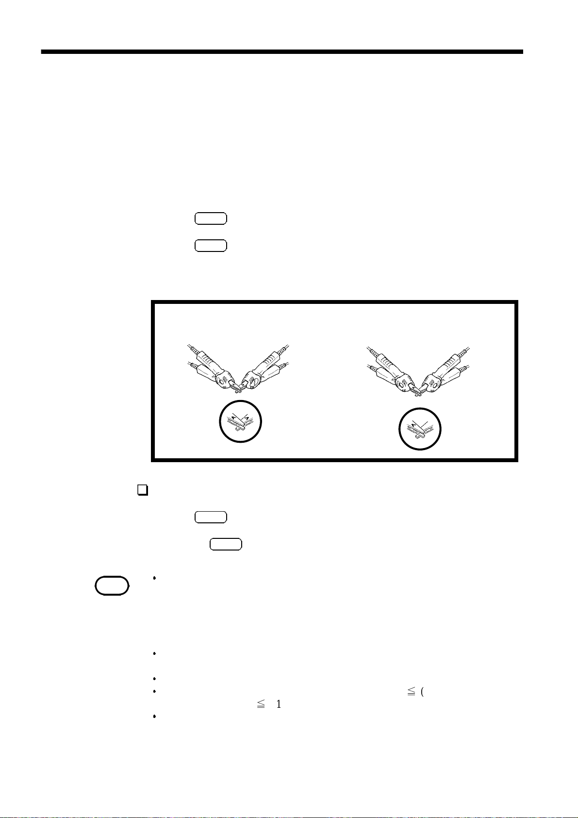
Zero-Adjust Procedure When Using the 4-terminal test leads (3239)
SENSE
SOURCE
SENSE
SOURCE
Correct connection
Bring the "v" marks together
at the same position.
SENSE
SOURCE
SOURCE
Wrong connection
Clearing the Zero-Adjust function
SENSE
SHIFT
."SHIFT" lights up on the display.
LOAD
clears the Zero-Adjust function.
NOTE
.Press
1
. Pressing
2
The Zero-Adjusted value is saved as an absolute value independent of a specific
range.
Example:
When 1.234 Ω is measured in the 200 Ω range and then Zero-Adjusted, 1.234 Ω
is also subtracted from the value measured in the 2000 Ω range before being
displayed.
In the case of an overload ("OF" displayed), the error message "
Err.002
"is
displayed. The Zero-Adjust function is unavailable under these conditions.
A Zero-Adjusted value can be set for each function.
If a value is not covered by the range of -1999 99 count≦(Measurement value -
" is displayed.
Zero-Adjusted value)≦+199999 count, "
OF
The Zero-Adjust function cannot be used with the continuity test function, diode
test function, or frequency measurement function.
______________________________________________________________________________________________
4.3 Zero Adjust function

_____________________________________________________________________________________________
25
4.4 Average function
The Average function outputs a mean value after averaging measurement
values. This function allows you to minimize the deviation of measurement
values.
The averaging can be set to 2 to 100 measurements.
1
2
3
NOTE
.Press
1
.Press
2
screen.
.Press to select the number of averaged measurements.
3
Press the simultaneously to clear the set value (002 times).
.Press
4
measurement is enabled.
Clearing the Average function
.Press
1
. Pressing
2
The Average function cannot be used with the continuity test function.
SHIFT
."SHIFT" lights up on the display.
SMPL
SHIFT
to display the number of averaged measurements setup
ENT
."AVE" lights up on the display, and averaging
."SHIFT" lights up on the display.
SMPL
clears the Average function.
4
5
6
7
8
9
Eliminating power line noise
Measurements are more consistent when the sampling is synchronized to the
power line cycle. However, the measurement period of 3.33 ms of the FAST
sampling is not synchronized to the power line cycle (except for some
functions and ranges).
To ensure the most consistent measurement values with "
recommend the following settings:
Power-supply
frequency
Number of averaged
measurements
These settings synchronize the measurement time with the sampling period
FAST to the power line cycle to ensure consistent and reliable
measurements.
6 x n measurements 5 x n measurements n: 1,2,3,
50 Hz 60 Hz
FAST", we
10
11
12
13
14
A
______________________________________________________________________________________________
4.4 Average function

26
_____________________________________________________________________________________________
4.5 Trigger Function
4.5.1 Setup for Trigger mode
The following two types of Trigger modes are available:
(1) Internal Trigger
Continuous measurement is performed with an automatically generated
internal trigger.
.Press
1
.Press
2
M.TRIG
Trigger mode is activated.
(2) External Trigger
Measurement is performed with a trigger applied externally or manually.
Press
M.TRIG
is activated.
NOTE
External Trigger mode is i nactive when the continuity test function is used.
4.5.2 External Trigger
The following three types of External Trigger are available:
(1) Applied through the front panel
SHIFT
."
SHIFT
" lights up on the display.
."M.TRIG" is no longer lit on the display, and Internal
."M.TRIG" lights up on the display, and External Trigger mode
Pressing
M.TRIG
on the front panel causes the unit to perform a single
measurement.
(2) Applied through EXT I/O
When a pulse is applied to the TRIG terminal of the EXT I/O connector on
the rear panel, the unit performs a single measurement. (See 6.1 Explanation
of Signals.)
(3) Applied through the interface
When the ∗TRG command is issued through the interface, the unit performs
a single measurement.
NOTE
______________________________________________________________________________________________
4.5 Trigger Function
When Internal Trigger remains active, all inputs through the EXT I/O connector and
the ∗TRG command are ignored.

_____________________________________________________________________________________________
27
4.5.3 Trigger Delay
1
The delay time from the application of a trigger signal until the start of
measurement is set. If this function is in use, measurement begins when the
measurement values have stabilized, even if a trigger is applied immediately
following the connection of the sample.
The following two types of trigger delay are available:
(1) Auto Delay
The unit automatically sets a delay time.
.Press
1
. Pressing
2
.Press to display the trigger delay setup screen.
3
. Pressing causes the currently set trigger delay to flash.
4
"AUt": Auto delay
"SEt": Manual delay
SHIFT
."SHIFT" lights up on the display.
ENT
displays the menu screen.
2
3
4
5
6
7
8
.Press to select auto delay ("AUt").
5
. Pressing
6
.Press
7
Wait Times of Auto Delay
DCV 3ms 3ms 3ms
ACV 500 ms 800 ms 1.5 s
DCA 3ms 3ms 3ms
ACA 500 ms 800 ms 1.5 s
Ω
LPΩ 2to20kΩ range 3ms 3ms 3ms
Hz 10 ms 10 ms 10 ms
200 Ω to 200 kΩ range 3ms 3ms 3ms
2MΩ range 20 ms 20 ms 20 ms
20 MΩ range 100 ms 100 ms 100 ms
100 MΩ range 500 ms 500 ms 500 ms
2MΩ, 200 kΩ range 20 ms 20 ms 20 ms
ENT
causes "dLy" to flash.
ENT
again to define your selection.
FAST MEDIUM SLOW
9
10
11
12
13
14
A
______________________________________________________________________________________________
4.5 Trigger Function

28
_____________________________________________________________________________________________
(2) Manual Delay
Any desired delay time can be set.
The trigger delay time can be set from 0.000 to 9.999 s in increments of 1
ms.
.Press
1
. Pressing
2
.Press to display the trigger delay setup screen.
3
. Pressing causes the currently set trigger delay to flash.
4
AUt
"
SHIFT
": Auto delay
SHIFT
."
ENT
" lights up on the display.
displays the menu screen.
"SEt": Manual delay
.Press to select manual delay ("SEt").
5
. Pressing
6
ENT
causes the values indicating the trigger delay time to
flash.
. Set a trigger delay time by pressing .
7
. Pressing
8
.Press
9
ENT
causes "dLy" to flash.
ENT
again to define your selection.
______________________________________________________________________________________________
4.5 Trigger Function
_____________________________________________________________________________________________
29
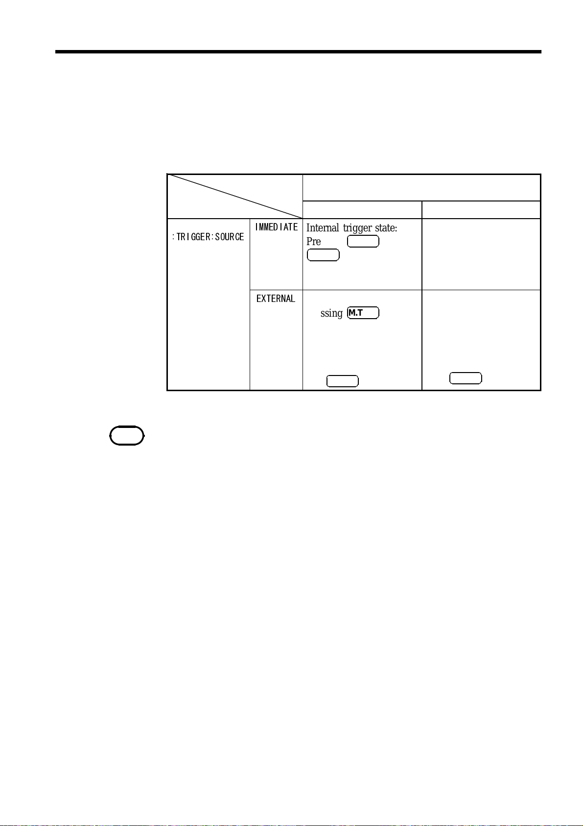
4.5.4 Trigger System
The trigger system functions as described further below, depending on the
setting for the Continuous trigger state (
Trigger Source (
:TRIGGER:SOURCE
). For trigger commands, refer to 7.4.3
"Specific Command Messages."
:INITIATE:CONTINUOUS
Continuous trigger state
:INITIATE:CONTINUOUS
ON OFF*
) or for the
NOTE
Trigger source
:TRIGGER:SOURCE
IMMEDIATE
Internal trigger state:
Pressing
M.TRIG
SHIFT
+
initiates this
Trigger is made on:
INITIATE (or :READ?)
state.
Free run.
EXTERNAL
External trigger state:
Pressing
M.TRIG
from
free run initiates this
state.
Trigger is made through
the TRIG terminal or
M.TRIG
with
.
The unit enters Wait
state for trigger on
:INITIATE (or
:READ?).
Trigger is made through
the TRIG terminal or
when
*: Can only be set by a remote command.
If the unit is switched off while it in
:INITIATE:CONTINUOUS ON/:TRIGGER:SOURCE EXTERNAL
switched on.
:INITIATE:CONTINUOUS OFF
M.TRIG
is pressed.
, it will be set to
when the unit is
______________________________________________________________________________________________
4.5 Trigger Function

30
_____________________________________________________________________________________________
:INITIATE:CONTINUOUS ON
:TRIGGER:SOURCE IMMEDIATE
Measurement
Computed result
Measurement value
output
:INITIATE:CONTINUOUS ON
:TRIGGER:SOURCE EXTERNAL
Wait state for trigger
TRIG terminal
M.TRIG
Trigger delay
Measurement
computed result
Measurement value
output
:INITIATE:CONTINUOUS OFF
:TRIGGER:SOURCE IMMEDIATE
Idle state
:INITIATE:IMMEDIATE
Trigger delay
Measurement
computed result
Measurement value
output
:INITIATE:CONTINUOUS OFF
:TRIGGER:SOURCE EXTERNAL
Idle state
:INITIATE:IMMEDIATE
Wait state for trigger
TRIG terminal
M.TRIG
Trigger delay
Measurement
computed result
Measurement value
output
______________________________________________________________________________________________
4.5 Trigger Function
_____________________________________________________________________________________________
q
31
Chapter 5
1
2
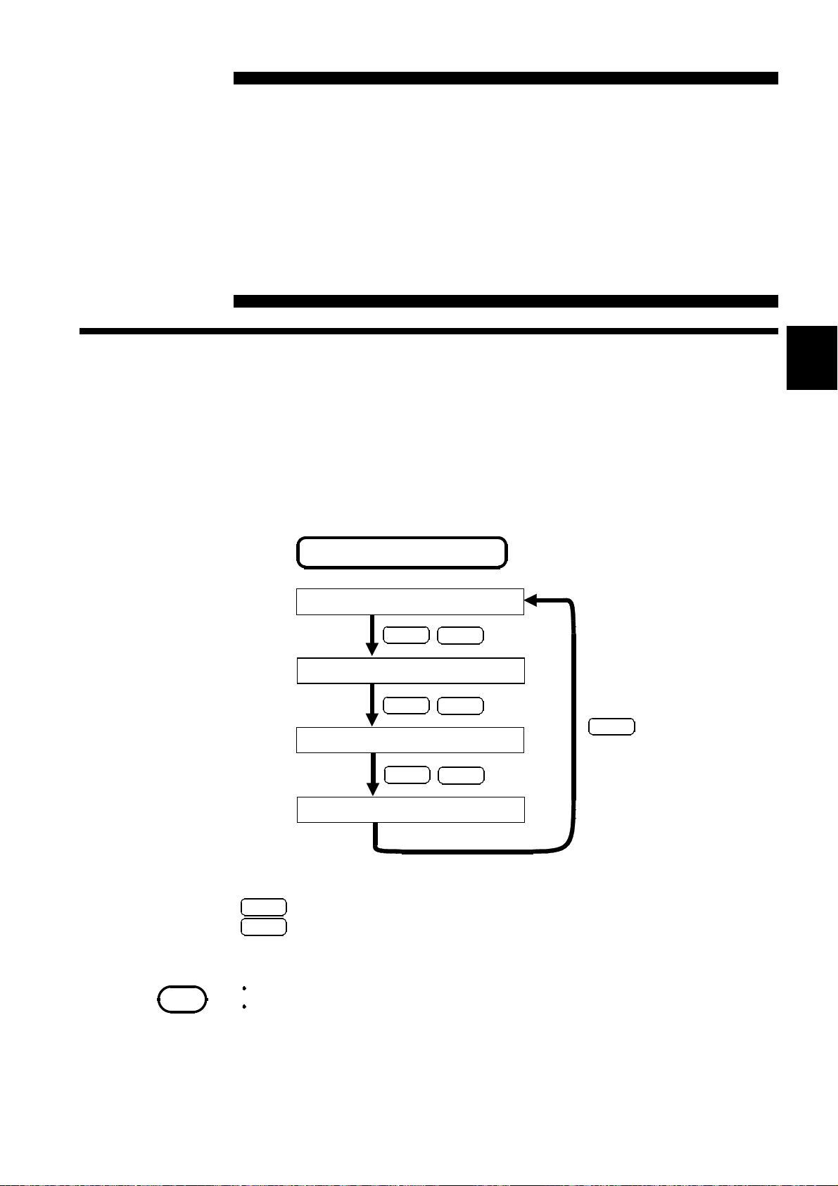
5.1 Comparator Function
The Comparator function compares the measurement value with the upperlimit and lower-limit values previously set, determines the appropriate range
for the measurement value, and displays the determination.
The flow of comparator setup is given below:
Setting of comparator
Measurement (comparator: OFF)
Other Functions
3
4
5
6
7
8
NOTE
ENT
The upper-limit value is set.
ENT
The lower-limit value is set.
ENT
Measurement (comparator: ON)
ENT
:
Confirms the current setting and proceeds to the next setup.
COMP
:
Proceeds to the next setup without confirming the current setting.
(Cancellation)
The Comparator function cannot be used in Auto Range.
The Comparator function cannot be used with t he continuity test
function or fre
uencymeasurement function.
COMP
COMP
COMP
COMP
9
10
11
12
13
14
A
______________________________________________________________________________________________
5.1 Comparator Function

32
_____________________________________________________________________________________________
Described below is the flow of operations from the measurement state with
comparator OFF to the start of the measurement state using the comparator.
In the following example, the upper-limit value will be set to 12 V and the
lower-limit value to 8 V.
(1) The upper-limit value is set.
1
.
Press
COMP
when the comparator is off.
"Hi" flashes, and the upper-limit value setup screen opens.
. Set the upper-limit value by pressing .
2
This is set to 12 V in the example.
(2) The lower-limit value is set.
1
.
Press
ENT
on the upper-limit value setup screen.
lower-limit value setup screen opens.
. Set the lower-limit value by pressing .
2
This is set to 8 V in the example.
(3) Turn the comparator ON.
Press
ENT
in the lower-limit value setup screen to initiate the
measurement state with the comparator ON.
"Lo"
flashes, and the
The comparator decides in which range the measurement value is covered
and displays the result. To enable the buzzer to beep depending on the
comparator determination, refer to 5.2 Setup for Comparator Buzzer Sound.
______________________________________________________________________________________________
5.1 Comparator Function

_____________________________________________________________________________________________
33
NOTE
To turn the comparator OFF
If you press
unit shifts to measurement with the comparator OFF.
Pressing
screen opens the following screen without altering the current upper-limit or
lower-limit value.
Whe n t h e co mp ar at or is ON, only t h e following k eys a r e active:
COMP,LOAD,SAVE,LOCA L(M.TRIG
is set )
The conditions for m e a su rm e nt wi th th e c omp arat or O N a re t ak e n from
th e conditions of th e m e as u re m en t condu cted wi th th e comp arat or
OFF.
The upper-limit a nd lower-limit values are saved as indication count
values t hat do not depend on the measurement functions or
measurement ranges. With a different measurement function or
different measurement range, the absolute values indicated by the
count va lues also change.
sFor example, specify 038000 to set t he lower-limit val ue to 380 mV in
the 2 V range of the
If th e u nit is switched off while in t he upper-limit value set up screen or
lower-limit value setup screen, the values entered during setup are
canceled an d th e previously set value s re tai ne d.
If t he com para tor is tu r ne d on while Auto R ange is active, Auto Ra nge
will be cleared.
If th e compar ator is t urn ed on while t he upper-limit value of th e
compa rat or is se t to a val ue s mal ler t h a n t he lower-limit value, th e
unit will indicate "
The relation b etween the thres hold a nd indication values a re a s follows:
Indication value > Upper-limit value : Hi
Upper-limit value≧Indication val ue≧Lower-limit value: IN
Lower-limit value > I ndication value: Lo
COMP
COMP
while the unit is measuring with the comparator ON, the
on the upper-limit value setup screen or lower-limit value setup
only when External Trigger
V function.
Err.004
", a nd th e compar ator will be t ur ne d off.
1
2
3
4
5
6
7
8
9
10
11
12
______________________________________________________________________________________________
5.1 Comparator Function
13
14
A

34
_____________________________________________________________________________________________
5.2 Comparator Buzzer Sound
Set the buzzer to sound at comparator determination.
NOTE
1
2
.
Press
.
Press
SHIFT
COMP
"
.
SHIFT
"
lights up on the display.
. The comparator buzzer sound setup screen opens, and the
current setting for the comparator buzzer flashes.
.Press to select the comparator determination that should activate the
3
buzzer.
"HL" : The buzzer beeps when the determination is Hi or Lo.
"In" : The buzzer beeps when the determination is In.
"OF" : The buzzer is not activated to beep, regardless of the comparator
result.
.
Press
4
The unit is set to "HL" at the factory before shipment.
ENT
. You are returned to the measurement screen.
______________________________________________________________________________________________
5.2 Comparator Buzzer Sound

_____________________________________________________________________________________________
35
5.3 Panel Save Function
The current measurement conditions are saved to the built-in nonvolatile
memory. A maximum of 30 different measurement conditions may be
saved. All the conditions in effect when Panel Save is executed are saved.
The saved measurement conditions can be loaded with the Panel Load
function described further below.
1
2
3
NOTE
.
Press
1
indicating the panel number flashes.
.Press to select the panel number you want to save.
2
.
Press
3
returned to the measurement screen.
When t he Panel Save screen opens, it indicates p anel n umb ers t ha t
have not been saved previously.
If you select a panel number under which you previously saved data and press
ENT
Interruption of Panel Save function
If you inadvertently opened the Panel Save screen, press
without pressing
The measurement screen will be restored without executing a Panel Save.
The following items are saved:
SAVE
. The Panel Save setup screen opens, and a numerical value
ENT
. The measurement conditions are saved, and you are
, the previously saved data will be overwritten.
ENT
.
SAVE
again
4
5
6
7
8
9
10
Measurement speed
Function
Range
ON/OFF for the comparator function
Upper/lower limit value of comparator
function
Comparator buzzer sound
Internal trigger/ external trigger
Auto delay/ manual delay
Trigger delay time
ON/OFF for the zero ajust function
Zero adjust value
ON/OFF for the average function
Number of averaged measurements
Kind of the clamp sensor
______________________________________________________________________________________________
5.3 Panel Save Function
11
12
13
14
A
36
_____________________________________________________________________________________________
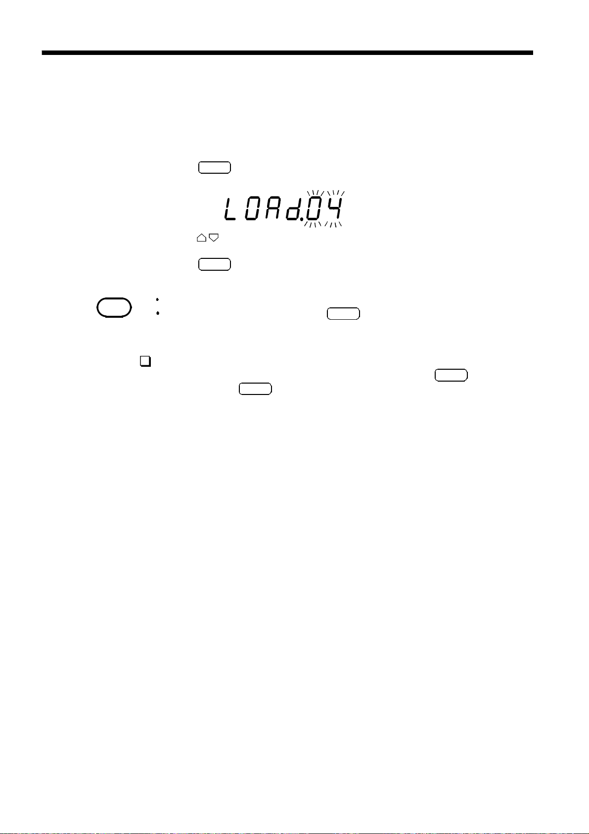
5.4 Panel Load Function
This function loads the measurement conditions saved by Panel Save from
the built-in nonvolatile memory.
NOTE
1
.
Press
LOAD
. The Panel Load setup screen opens, and the numerical
value indicating the panel number flashes.
.Press to select the panel number from which you want to load data.
2
3
.
Press
ENT
. The measurement conditions are loaded, and you are
returned to the measurement screen.
For panel number selection, tables not saved are skipped.
When a System Reset is performed,
number has been saved.
LOAD
becomes inactive, since no panel
Interruption of Panel Load function
If you inadvertently opened the Panel Load screen, press
without pressing
ENT
.
LOAD
again
The measurement screen will be restored without executing a Panel Load.
______________________________________________________________________________________________
5.4 Panel Load Function

_____________________________________________________________________________________________
37
5.5 Key Operation Sound
The setting made here determines whether or not the key operation sound
should be emitted when a key is pressed on the front panel of the main unit.
.
Press
1
.
Pressing
2
.Press to display the key operation sound setup screen.
3
. Pressing causes the current setting for the key operation sound to flash.
4
SHIFT
ENT
"
.
"
SHIFT
lights up on the display.
displays the menu screen.
"On": Key operation sound emitted
"OF": Key operation sound not emitted
.Press to select On or Off.
5
.
Pressing
6
.
Press
7
ENT
causes
ENT
again to define your selection.
"
bEEP
"
to flash.
______________________________________________________________________________________________
5.5 Key Operation Sound
38
_____________________________________________________________________________________________
5.6 Key Lock Function
When Key Lock is executed, the key switches on the front panel are
disabled. The set data can be protected with the Key Lock function.
. Set measurement conditions.
1
NOTE
NOTE
2
3
.
Press
.
Press
SHIFT
LOCA L
"
.
SHIFT
"
lights up on the display.
to initiate the Key Lock state.
When the unit is in Key Lock status, the following keys remain active:
LOCA L,SHIFT,M.TRIG
Clearing the Key Lock function
.
Press
1
.
Pressing
2
The Key Lock function is not deactivated even if the uni t is switched
off.
M.TRIG
active.
SHIFT
cannot be used when Key Lock is activated with the Internal Trigger
.
LOCA L
"
SHIFT
"
lights up on the display.
clears the Key Lock function.
______________________________________________________________________________________________
5.6 Key Lock Function

_____________________________________________________________________________________________
39
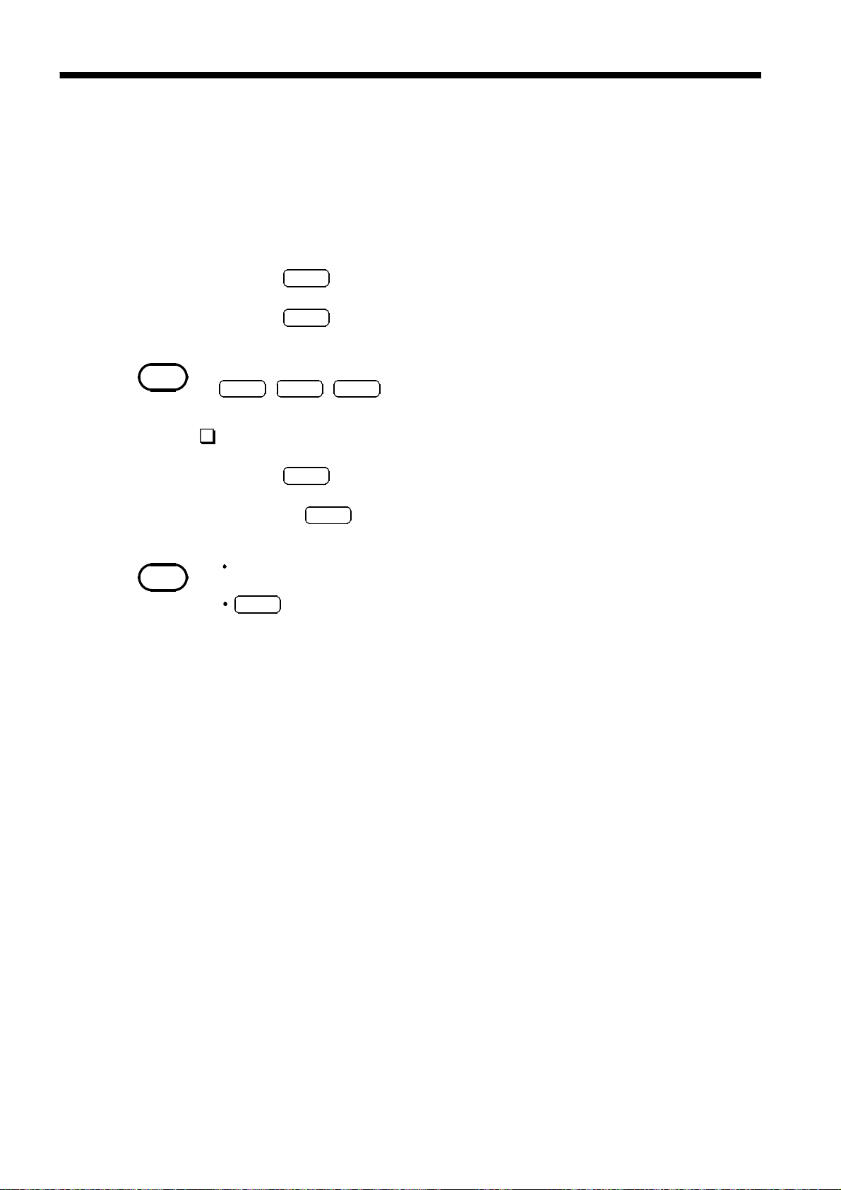
5.7 Remote Function
This unit can be controlled externally through the RS-232C or GP-IB
interface. When the unit is placed in remote status (remote operation state),
"RMT" on the display lights up, and the keys on the front panel are disabled.
Clearing the Remote function
Pressing
LOCA L
clears the Remote function.
NOTE
Even aft er r emot e s t at u s ha s been cleared, t he un i t will ree nt e r re mote
st atu s if externally controlled t hroug h the RS-232C or GP-IB interface.
When the trigger source is external (
can be used even while the unit is in remote status.
:TRIGGER:SOURCE_EXTERNAL
),
M.TRIG
______________________________________________________________________________________________
5.7 Remote Function

40
_____________________________________________________________________________________________
5.8 System Reset
System Reset is a function designed to initialize all measurement conditions
to their initial factory settings. Performing a System Reset also initializes
data stored via Panel Save.
.
Press
1
.
Pressing
2
.Press to display the system reset setup screen.
3
. Pressing causes "On" to flash.
4
.
Pressing
5
If
SHIFT
ENT
ENT
ENT
is pressed with
"
.
SHIFT
"
lights up on the display.
displays the menu screen.
runs System Reset.
"
"
rSEt
flashing, the unit will not perform a
System Reset.
______________________________________________________________________________________________
5.8 System Reset

_____________________________________________________________________________________________
41
The unit factory settings are as follows:
Measurement function DCV Low-power 2-terminal resistance
DC voltage measurement: range Auto range 4-terminal resistance measurement:
AC voltage measurement: range Auto range Low-power 4-terminal resistance
2-terminal resistance measurement:
range
Low-power 2-terminal resistance
measurement: range
4-terminal resistance measurement:
range
Low-power 4-terminal resistance
measurement: range
Frequency measurement: attenuator
range
DC current measurement: range Auto range Trigger delay time 0.000 s
AC current measurement: range Auto range Trigger delay AUTO
DC voltage measurement: zero ajust
value
AC voltage measurement: zero ajust
value
Auto range DC current measurement: zero ajust
Auto range AC current measurement: zero ajust
Auto range Sampling Period SLOW
Auto range Number of averaged measurements 2
2V Average function OFF
0 Power supply frequency 60 Hz
0 Clamp sensor 9010
measurement: zero ajust function
zero ajust function
measurement: zero ajust function
function
function
OFF
OFF
OFF
OFF
OFF
2-terminal resistance measurement:
zero ajust value
Low-power 2-terminal resistance
measurement: zero ajust value
4-terminal resistance measurement:
zero ajust value
Low-power 4-terminal resistance
measurement: zero ajust value
DC current measurement: zero ajust
value
AC current measurement: zero ajust
value
DC voltage measurement: zero ajust
function
AC voltage measurement: zero ajust
function
2-terminal resistance measurement:
zero ajust function
NOTE
does not clear interface data.
∗
RST
0 Key operation sound ON
0 Key lock OFF
0 Comparator OFF
0 Comparator: upper limit value 000000
0 Comparator: lower limit value 000000
0 Comparator: buzzer sound HL
OFF Interface RS-232C
OFF Panel save All clear
OFF
______________________________________________________________________________________________
5.8 System Reset

42
_____________________________________________________________________________________________
5.9 Measurement States and Effective Keys
Condition FUNCTION AUTO COMP
Normal
LOCK
RMT
COMP
● ● - ● ● ●
- - - - - -
- - - - - -
- - - - ● ●
Condition M.TRIG INT.TRIG LOAD SAVE 0ADJ LOCAL
Normal
LOCK
RMT
COMP
● ● ● ● ● -
1
●
●
●
*
2
*
1
*
- - - - -
- - - - ●
- ● ● - -
Condition LOCK SMPL AVE ENT MENU SHIFT
Normal
LOCK
RMT
COMP
● ● ● ●
● - - - - ●
- - - - - -
● - - ●
3
*
3
*
● ●
- ●
*1: Only when External Trigger is active.
*2:
:TRIGGER:SOURCE_EXTERNAL
*3: When the Interface setting is set to printer.
______________________________________________________________________________________________
5.9 Measurement States and Effective Keys

_____________________________________________________________________________________________
43
Chapter 6
1
2
External Control Terminal
/ External output terminal
(1) External control terminal functions
External trigger input
Selection of panel number to be loaded
(2) External output terminal function
Measurement end signal output
Output of comparator determination signal
(3) Connectors in use
57RE-40360-730B(D29) (DDK Ltd)
(4) Acceptable connector
JC57-30360 (JC Electronics Corporation)
Or, their equivalent.
3
4
5
6
7
8
9
18
36
19
1
10
11
12
13
14
A
______________________________________________________________________________________________

44
_____________________________________________________________________________________________
6.1 Explanation of Signal Wires
CAUTION
To prevent damage to this unit, please observe the following precautions:
Do not apply a voltage or current exceeding the rated values to the external
output terminal or external control terminal.
When using a relay, always attach a flyback diode.
Take care not to short-circuit the external output terminal and the external
control terminal.
Take care not to short-circuit INT.DCV and INT.GND.
When a device is to be coupled to the external output terminal or external
control terminal, be sure to connect the device to ground. Failure to do so
may destroy measurement system insulation.
To prevent electric shock, please observe the following precautions:
When a device is to be connected to this unit, switch it off before coupling
it to the terminal. Establish cable connections securely to prevent
dislocation during operations and subsequent contact with conductive parts
of the unit casing or test leads.
INT.GND is connected to ground. If a controller has a potential to ground,
a short-circuit will occur.
Pin No. I/O Signal line name Pin No. I/O Signal line name
1 IN LOAD0
2 IN LOAD2
3 IN LOAD4
4 IN TRIG
―――――
―――――
―――――
――――
19 IN LOAD1
20 IN LOAD3
21 IN (Reserved)
22
-
―――――
―――――
Not used
5 OUT INT.DCV 23 OUT INT.GND
6 OUT INT.DCV 24 OUT INT.GND
7 OUT INT.DCV 25 OUT INT.GND
8 OUT INT.DCV 26 OUT INT.GND
10
9
-
-
No connection 27
No connection 28
-
-
No connection
No connection
11 OUT (Reserved) 29 OUT (Reserved)
12 OUT (Reserved) 30 OUT (Reserved)
13 OUT EOC
14 OUT IN
―――
――
31 OUT Hi
32 OUT Lo
――
――
15 OUT INT.DCV 33 OUT INT.GND
16 OUT INT.DCV 34 OUT INT.GND
17 OUT INT.DCV 35 OUT INT.GND
18 OUT INT.DCV 36 OUT INT.GND
______________________________________________________________________________________________
6.1 Explanation of Signal Wires

_____________________________________________________________________________________________
―――――――――
(1) LOAD0
―――――――――
~LOAD4
45
These signals select the panel number from which to load data.
When a trigger signal is applied in External Trigger mode, the unit loads
data from the selected panel number and performs a measurement.
―――――――――
LOAD0
(The number 0 indic ates that the LOAD
number 1 indicates tha t the LOAD
*: When LOAD0
is the LSB, and LOAD4
―――――――――
LOAD4
1 1 1 1 1 *
1 1 1 1 0 1
1 1 1 0 1 2
1 1 1 0 0 3
1 1 0 1 1 4
1 1 0 1 0 5
1 1 0 0 1 6
1 1 0 0 0 7
1 0 1 1 1 8
1 0 1 1 0 9
1 0 1 0 1 10
1 0 1 0 0 11
1 0 0 1 1 12
1 0 0 1 0 13
1 0 0 0 1 14
1 0 0 0 0 15
0 1 1 1 1 16
0 1 1 1 0 17
0 1 1 0 1 18
0 1 1 0 0 19
0 1 0 1 1 20
0 1 0 1 0 21
0 1 0 0 1 22
0 1 0 0 0 23
0 0 1 1 1 24
0 0 1 1 0 25
0 0 1 0 1 26
0 0 1 0 0 27
0 0 0 1 1 28
0 0 0 1 0 29
0 0 0 0 1 30
0 0 0 0 0 *
―――――――――
―――――――――
LOAD3
to LOAD4
―――――――――
―――――――――
―――――――――
is the MSB.
―――――――――
terminal should be shorted by the INT.GND, and the
terminal should be open.)
―――――――――
LOAD2
―――――――――
LOAD1
―――――――――
LOAD0
―――――――――
are all set to 1, or when LOAD0
Panel NO.
―――――――――
to LOAD4
are
all setto 0, even if a trigger signal is applied, data loading from a panel
doesnot take place, because there is no panel number corresponds to them.
――――――
(2) TRIG
This signal places the unit in External Trigger mode. If you change
――――――
TRIG
signal from Hi to Lo, the unit will measure once at the edge.
If the interface is set to Printer, the unit performs a single measurement and
outputs the result to the printer. For more information on printers, refer to
Chapter 9. Printer Interface.
(3) INT.DCV, INT.GND
These signals output the internal 5 VDC of this unit and the internal GND.
1
2
3
4
5
6
7
8
9
10
11
12
13
14
A
______________________________________________________________________________________________
6.1 Explanation of Signal Wires
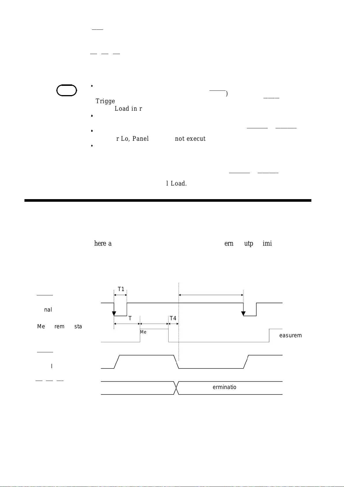
46
_____________________________________________________________________________________________
―――――
(4) EOC
This is a measurement end signal.
―――
―――
(5) Hi
,IN
―――
,Lo
These are comparator determinations.
NOTE
In t h e following cases , in p u t s ig na ls will b e ineffective.
Trigger i n t h e I n te r na l Tr igger mode (TRIG
Trigger in a ny screen oth er t h an mea su rem ent screens (TRIG
Panel Load in remote st atus.
If no me as u re m en t is conducted af ter th e power is t u r ne d on, all t h e
outpu t signals (open collector) will go off.
If a trigger signal is applied to the un it wi th all of LOAD0
to Hi or Lo, P ane l Loa d is not executed.
If measurement is initiated after Panel Load has been executed and the
me as u re me n t conditions h ave been alte red , m ea s ur e me nt val ues will
take at least 10 ms to stabilize. (Stabilization time varies with function,
ra ng e , an d t h e sa m pl in g period.)
To conduct m e as u re m en ts quickly, s et all of LOAD0
Lo after executing Panel Load.
6.2 Timing Chart
There are two kinds of external control and external output timings for
External Trigger mode and Internal Trigger modes, as follows.
―――――――
)
―――――――――
―――――――
―――――――――
―――――――――
- LOA D4
).
―――――――――
- LOA D4
to Hi or
set
(1) External trigger mode
―――――――
TRIG
Measurement start
signal
Measurement state
―――――――
EOC
Measurement end
signal
―――
―――
,IN
―――
,Lo
Hi
Comparator result output
T1
T2 T3
Idle state
Measurement
in progress
Previous determination
T4
T5
Idle state
Determination
Measurement
______________________________________________________________________________________________
6.2 Timing Chart
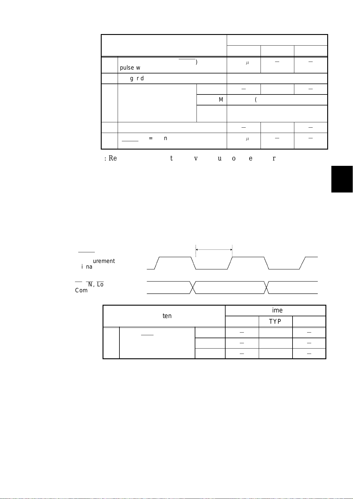
_____________________________________________________________________________________________
47
Contents
T1 Measurement trigger ( TRIG
pulse width
T2 Trigger delay time Refer to 4.5.3 Trigger Delay
T3 Measuring time* FAST
T4 Computing time
T5 From EOC=Lo until input of trigger
―――――――
( TRIG
)
―――――――
)
MEDIUM 130 ms (50 Hz) / 108 ms (60 Hz)
SLOW 1.04 s (50 Hz) / 1.08 s (60 Hz)
MIN TYP MAX
500μs
-
-
500μs
Time
- -
3.3 ms
2ms
- -
*: Reference value. With the Average function, the measuring time is
determined by multiplying the measuring time by the number of averaged
measurements.
This varies with the function range. Use the sampling period (free run) in
Chapter 10 Specification as a guide.
When set to FAST, the unit performs a self-calibration every 30 minutes
for a duration of approximately 55 ms each time.
-
-
1
2
3
4
5
6
7
(2) Internal trigger mode
―――――――
EOC
Measurement end
signal
―――
―――
,IN
―――
,Lo
T6 Measurement end
signal (EOC
pulse width
Hi
Comparator result output
Contents
―――
T6
9
10
8
Time
MIN TYP MAX
)
FAST
MEDIUM
SLOW
-
-
-
1.7 ms
50 ms
500 ms
-
-
-
11
12
13
______________________________________________________________________________________________
6.2 Timing Chart
14
A

48
_____________________________________________________________________________________________
6.3 Internal Circuit Configuration
(1) Power rating for external control and output terminals
Input/output device Logic Electrical
requirements
Output Open collector Negative logic DC35 V, DC50 mAmax.
Input C-MOS Negative logic H: 3.8~to 5.0 V,
INT.DCV Internal power supply
output
(2) Application of external output terminal
Connection of the relay
Connection of the LED
(3) Application of external control terminal
L: 0 to 1.2 V
DC5±10%,
DC50 mAmax.
Connection of
negative logic output
Progammable
controller
Connection of the
Connection of the relay
switch
(4) Circuit configuration of external control terminal
(5) Circuit configuration of
Connection of the
progammable controller
external output terminal
______________________________________________________________________________________________
6.3 Internal Circuit Configuration

_____________________________________________________________________________________________
49
Chapter 7
1
2
RS-232C Interface
RS-232C Interface enables all 3237/38/39 controls except 3237/38/39 power
switch.
RS-232C and GP-IB (-01) cannot be used simultaneously. Select either of
them. For information on performing the selection, refer to 7.1 Preparations
for Communication.
(1) Specifications
3237/38/39 RS-232C settings are configured as follows and cannot be
modified. Modify and adjust personal computer settings.
Transmission mode Start-stop synchronization, full duplex
Transfer rate 9600 bps
Data length 8 bit
Parity None
Stop bit 1bit
3
4
5
6
7
8
9
Hand shake No X flow, hardware flow control
Delimiter CR, CR + LF for reception
CR + LF for transmission
10
11
12
13
14
A
______________________________________________________________________________________________
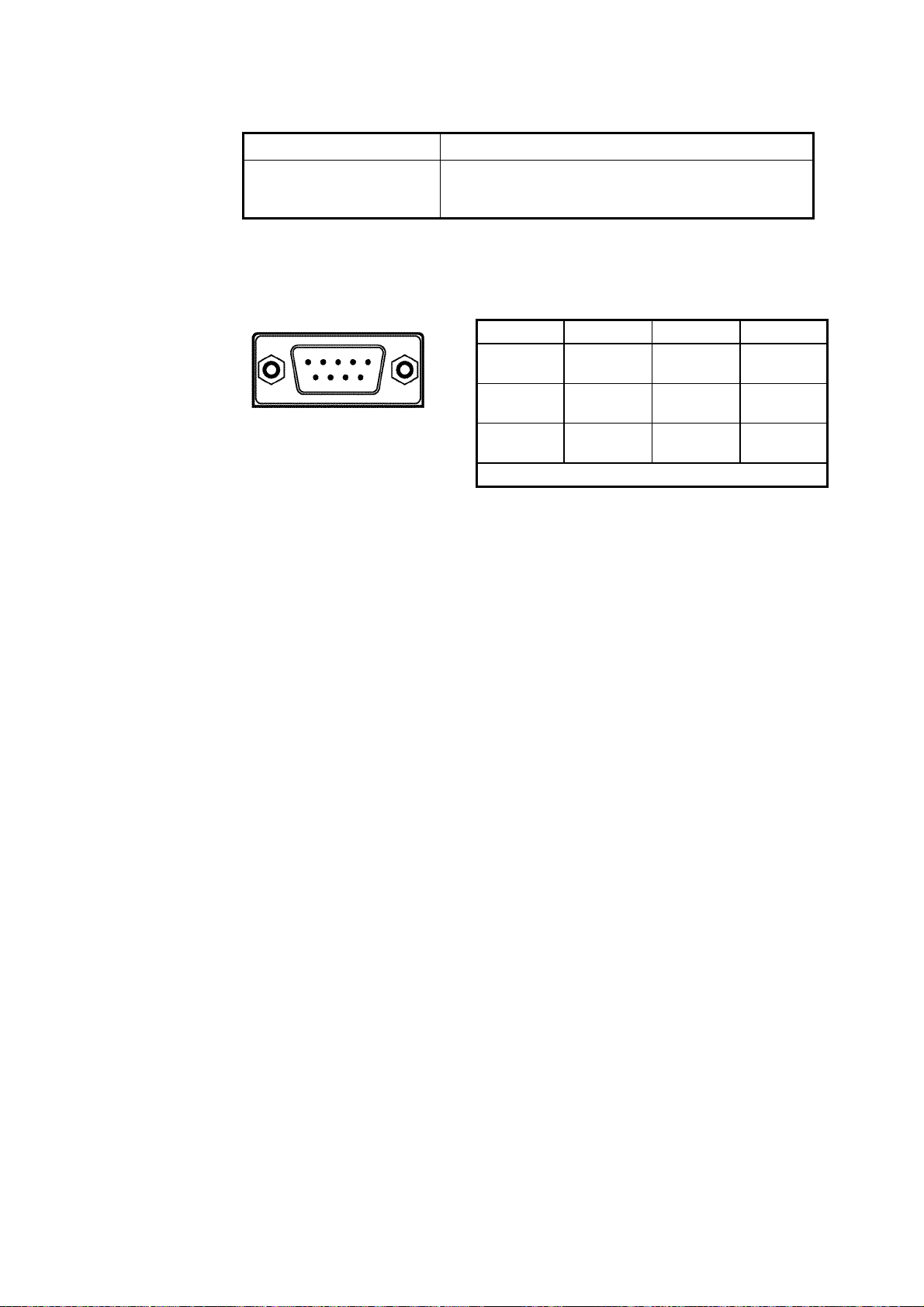
50
_____________________________________________________________________________________________
(2) Electric specifications
Input voltage level +5 V to +15 V: ON, -15 V to -5 V: OFF
Output voltage level
(Load resistance 3 to 7
kΩ)
+5 V to +9 V: ON, -9 V to -5 V: OFF
3237/38/39 RS-232C connector signal lead is set as follows.
Other pins are not in use.
Interface connector: D-sub 9 pin, male
Pin Signal IN/OUT Purpose
12345
6789
2 RxD IN Receiving
3 TxD OUT Sending
5 GND GND Signal
Do not use other pins.
data
data
grounding
______________________________________________________________________________________________
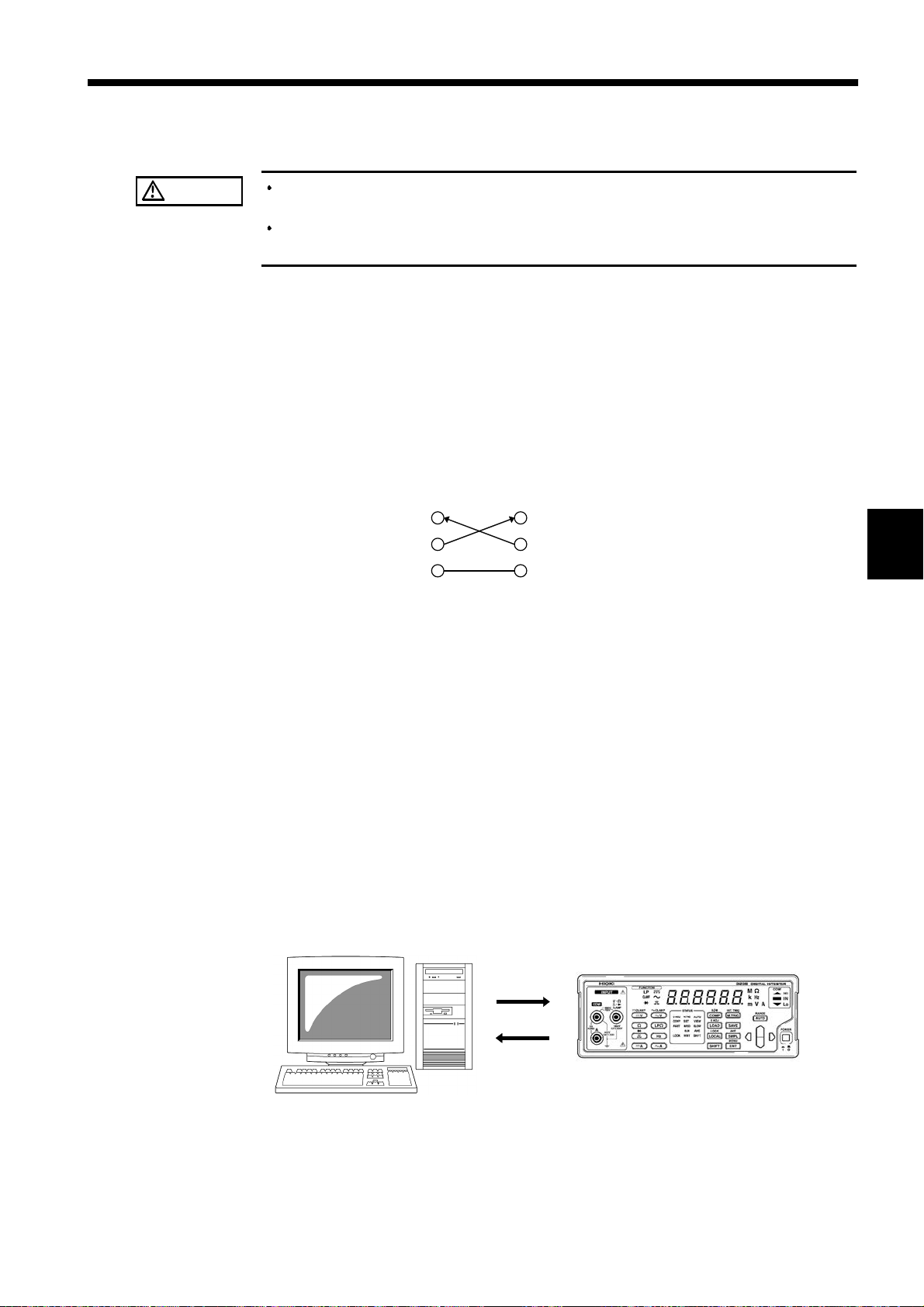
_____________________________________________________________________________________________
51
7.1 Preparing for Data Transfer
1
CAUTION
To avoid electrocution, turn off the power to all devices before plugging or
unplugging any of the interface connectors.
To avoid damage to the product, do not short-circuit the output terminal
and do not input voltage to the output terminal.
(1) Connecting Connection Cables
Use 9637 RS-232C CABLE or 9638 RS-232C CABLE to connect with
personal computer.
When using any other cables, choose a cross cable that allows sending data
and receiving data and is connected with signal lead and ground lead.
No other particular wiring is required.
3237/38/39
RxD
TxD
GND
Cable connector on the unit
Wiring: Reverse wiring
When connecting with PC/AT compatible computers: 9637 RS-232C
CABLE
When connecting with NEC PC 98 series: 9638 RS-232C CABLE
Personal computer
RxD
TxD
GND
2
3
4
5
6
7
8
9
(2) Connecting 3237/38/39 and Personal Computer
. Use cable to connect 3237/38/39 and personal computer.
1
. After connecting, turn on both 3237/38/39 and personal computer power.
2
. Set RS-232C in personal computer.
3
Set hardware flow OFF in personal computer flow control setting.
For settings, see individual software instruction manual.
10
11
12
13
14
A
______________________________________________________________________________________________
7.1 Preparing for Data Transfer

52
_____________________________________________________________________________________________
(3) 3237/38/39 Interface Setting
Designate 3237/38/39 Interface setting "
rS"(RS-232C) to enable 3237/38/39
Interface to communicate with personal computer.
.
Press
1
.
Pressing
2
.
Press to display the interface setup screen.
3
.
Pressing causes the interface currently set to flash.
4
"rS" : RS-232C
"
"
.
Press to select
5
.
Pressing
6
SHIFT
" : Printer
Prn
" : GP-IB
gPIb
.
ENT
ENT
"
"
SHIFT
lights up on the display.
displays the menu screen.
RS-232C ("rS")
causes
"IF"
to flash.
.
NOTE
.
Press
7
The unit is shipped from the factory with the interface set to RS-232 C.
ENT
again to define your selection.
______________________________________________________________________________________________
7.1 Preparing for Data Transfer

_____________________________________________________________________________________________
53
7.2 Communication
Command is sent out from personal computer to 3237/38/39.
After receiving command, 3237/38/39 processes operation according to the
command.
When personal computer sends inquiry command (command with "?"),
3237/38/39 sends back corresponding response.
During communication, 3237/38/39 front panel "RMT"isturnedoninremote
status.
LOCA L
.
Command Format
Remote status disables all operations except
Press
local status.
LOCA L
to disengage remote status (communication) and returns to
1
2
3
4
5
6
(1) Command Format
The 3237/38/39 commands have the following structure.
Command (+Parameter)
The command and the parameter are separated by ""(one character space)
If there is no parameter, send the delimiter after the command.
The command may consist of both upper and lower case letters.
Make sure to use one character space as the separator between the command
and the parameter.
① When the co mmand contains a parameter
:VOLTage:RANGe 100 (+delimiter)
the command format consists of the command :VOLTage:RANGe followed
by the separator ""(one character space). Then follows the parameter "100".
Following the parameter comes the delimiter
② When the co mmand contains no parameter
:INIT (+delimiter)
the command format consists of the command :INIT immediately followed
by the delimiter.
Delimiter
7
8
9
10
11
12
NOTE
______________________________________________________________________________________________
The meaning of the delimiter is to separate commands and data. When the
3237/38/39 receives the delimiter, it starts analysis of the command.
7.2 Communication
13
14
A

54
_____________________________________________________________________________________________
(2) Command/Parameter/Delimiter
① Command
A command can abbreviated. The whole command form is referred to as the
"long form" and the abbreviated form as the "short form."
Although the short form is printed in upper case letters and the rest in lower
case letters in this instruction manual, sending command (including
parameter and delimiter) from personal computer in either upper or lower
case letters is valid.
All responses returned from the 3237/38/39 are in upper case letters.
VOLTage OK (the long form)
VOLT OK (the short form)
VOLTA,VOL error
A command consisting of a single word beginning with a letter.
Examples: :READ? etc.
A command consisting of a sequence of words separated by colons.
Examples: :SYSTem:BEEPer, :MEASure:VOLTage? etc.
A command beginning with an asterisk (∗) to indicate that is a
particular co mmand.
Examples: ∗RST etc.
② Parameter
Character data and decimal data are used as the 3237/38/39 parameter (data)
and the command determines the type of data. The 3237/38/39 uses
character string data and numeric data, and the type use varies according to
the command in question.
Character data
Character string data must always begin with an alphabetic character, and
the characters following can be either alphabetic characters or numerals.
Although in character data either upper case letters or lower case letters are
accepted, response message output by the 3237/38/39 are always in upper
case letters.
Decimal data
The numeric data values are all represented in decimal, in three formats
identified as NR1, NR2 and NR3, and each of these can appear as either a
signed number or an unsigned number. Unsigned numbers are taken as
positive.
NR1 format: Integer data
Example: +12, -23, 34
NR2 format: Fixed point number
Example: +1.23, -23.45, 3.456
NR3 format: Floating point number
Example: +1E-2, -2.3E+4
The term "NRf format" includes all these three formats.
Each 3237/38/39 command designates a format.
______________________________________________________________________________________________
7.2 Communication

_____________________________________________________________________________________________
s
55
③ Delimiter
Depending on transmission direction, the delimiter is as follows.
From computer to 3237/38/39: CR or CR + LF
From 3237/38/39 to computer: CR + LF
(3) Separators
① Command unit separator
Multiple commands can be written in a line by connecting them with a
semicolon";".
Example: FUNCtion 'VOLTage';VOLTage:RANGe 100
Multiple query commands can also be in a line. Response is returned in a
line with each responding data separated by a semicolon";". Writing multiple
commands without inserting semicolons results in text error failing to
complete command execution.
② Separator between command and parameter
Use space" " in command with both command and parameter to separate
command and parameter.
Example: VOLTage:RANGe 100
Compound Command Header Omission
When several commands having a common header are combined to form a
compound command (e.g., :CALCulate:LIMit:UPPer and
:CALCulate:LIMit:LOWer), if they are written together in sequence, the
common portion (here, :CALCulate:LIMit:)
can be omitted after its initial occurrence.
This common portion is called the“current path”(analogous to the path
concept in computer file storage), and until it is cleared, the interpretation of
subsequent commands presumes that they share the same common portion.
This usage of the current path is shown in the following example:
Full expression
:CALC:LIM:UPP 150000;:CALC:LIMit:LOW 120000
Compacted expression
:CALC:LIMit:UPP 150000;LOW 120000
This portion becomes the current path, and can be omitted from the message
immediately following.
The current path is cleared when the power is turned on, when reset by key
input, by a colon“:”at the start of a command, and when a message
terminator is detected.
Standard command messages can be executed regardless of the current path.
They have no effect upon the current path.
Acolon“:”is not required at the start of the header of a Simple or
Compound command. However, to avoid confusion with abbreviated forms
and operating mistakes, we recommend always placing a colon at the start of
aheader.
______________________________________________________________________________________________
7.2 Communication

56
_____________________________________________________________________________________________
Data Format
① Inquiry without read value
String of not more than 64 ASCII characters.
② Measurement data
There are 2 ways measurement data is formatted.
Default data uses Format 1.
FORMAT1
(-)D.DDDDDDDDESDD + delimiter
( ) are used only when there is a negative value. Left-justify the entire
line when the value is positive.
D: Digit
E: Exponential
S: +/- signs
FORMAT2 (Software version 2.05 or later)
The FORMat command is used to make the setting.
The settings are in effect until the power is turned off.
Format 1 will be the active method upon restarting or resetting the
instrument.
For more information, please refer to APPENDIX (6) "Using FORMAT2
on Measurement Data."
Output Queue
③ Over flow
Positive: 9.900000E+37
Negative: -9.900000E+37
④ ON/OFF for header
Header can be set ON or OFF for some of the responses.
The HEADer command is used to make the setting.
Examples of responses with the header ON and OFF are given below.
Example: Response when the trigger delay is set to 0.5 s.
Inquiry: TRIGer:DELay? (Command to inquire about delay time).
Response: (Trigger delay is 500 ms)
When the header is ON (Command part + parameter part)
:TRIGGER:DELAY 5.000000E-01
When the header is OFF (Parameter part only)
5.000000E-01
Response messages accumulated in the output queue and are transmitted as
data and cleared. The output queue is also cleared when the power is turned
off and turned on again. The 3237/38/39 has an output queue of 64 bytes
capacity. If the response messages overflow this limit of 64 bytes, a query
error is generated, and the output queue is cleared.
Input Buffer
The 3237/38/39 has an input buffer of 64 bytes capacity. When more than
64 bytes of data are transmitted, when the buffer is full any subsequent bytes
received will be ignored.
______________________________________________________________________________________________
7.2 Communication

_____________________________________________________________________________________________
)
)
57
Status Byte Registers
(1) Status byte register (STB)
The status byte register is an 8-bit register whose contents are output from
the 3237/38/39 to the controller, when serial polling is being performed.
If even only one bit in the status byte register has changed from 0 to 1
(provided that it is a bit which has been set in the service request enable
register as a bit which can be used), then the MSS bit is set to 1.
Simultaneously with this the SRQ bit is set to 1, and service request is
generated.
bit7 bit6 bit5 bit4 bit3 bit2 bit1 bit0
Not used
MSS ESB MAV
Not used Not used Not used
Status byte registers(STB
ESB0
Logical
sum
bit7 bit6 bit5 bit4 bit3 bit2 bit1 bit0
Not used
×
&
ESB MAV
Service request enable registers(SRER
&
Not used Not used Not used
&
ESB0
Although the MSS bit is read out on an ∗STB?query,ona∗CLS command
for example it is not cleared until the event is cleared.
Bit 7
Bit 6
MSS
Bit 5
ESB
Bit 4
MAV
Bit 3
Bit 2
Not used
MSS shows the logical sum of other bits in the status byte register.
Standard event summary (logical sum) bit
ESB shows the logical sum of the standard event status register.
Message available
MAV indicates the output queue has messages.
Not used
Not used
Bit 1
Bit 0
ESB0
Not used
Event summary (logical sum) bit 0
ESB0 shows the logical sum of the event status register 0.
(2) Service request enable register (SRER)
This register masks the status byte register. Setting a bit of this register to 1
enables the corresponding bit of the status byte register to be used.
______________________________________________________________________________________________
7.2 Communication

58
)
)
_____________________________________________________________________________________________
Standard Event Registers
(1) Standard event status register (SESR)
The standard event status register is an 8-bit register. If any bit in the
standard event status register is set to 1 (after masking by the standard event
status enable register), bit 5 (ESB) of the status byte register is set to 1.
bit6
RQS
MSS
Standard event status registers(SESR
bit5
ESB
Logical
sum
bit7 bit6 bit5 bit4 bit3 bit2 bit1 bit0
PON URQ CME EXE DDE QYE RQC OPC
&
bit7 bit6 bit5 bit4 bit3 bit2 bit1 bit0
PON URQ CME EXE DDE QYE RQC OPC
&
&
Standard event status enable registers(SESER
&&&
& &
The standard event status register is cleared in the following four situations:
① When a ∗CLS command is received.
② When an ∗ESR? query is received.
③ When the unit is powered on.
④ When the I/F is Switched.
______________________________________________________________________________________________
7.2 Communication

_____________________________________________________________________________________________
59
(2) Standard event status enable register (SESER)
Setting any bit of the standard event status enable register to 1 enables the
corresponding bit of the standard event status register to be accessed.
Bit 7
PON
Bit 6
URQ
Bit 5
CME
Bit 4
EXE
Bit 3
DDE
Power-on flag
PON is set to "1" when the 3237/38/39 is turned on or restored from
a power failure and switching the interface.
User request
This bit is not used in the 3237/38/39.
Command error (Commands up to the message terminator are
ignored.)
CME is set to "1" when the command received has the following
syntax or interpretation errors:
A command not defined in the 3 237/38/39 is received.
The program header is invalid.
The data quantity differs from the specified value.
The data format differs from that specified.
Execution error
EXE is set to "1" when the command received cannot be executed
because:
The specified data deviates from the specified range.
The specified data is not acceptable.
Error resulting from device malfunction.
DDEissetto"1" if the command cannot be executed for any reason
other than command, query, or execution errors.
The command cannot be executed, due to an error within the
3237/38/39.
The command cannot be executed, because another function is
already active.
Bit 2
QYE
Bit 1
RQC
Bit 0
OPC
Query error (The output queue is cleared.)
The query error is detected by the output queue controller and QYE
set to "1" when the following events occur:
An attempt is made to read an empty output queue.
Deadlock state
The next message is received while the output queue contains data.
A query exists after the ∗IDN? query on the same line.
Controller privilege request
This bit is not used in the 3237/38/39.
Operation complete
OPC is set to "1" when (for example) the ∗OPC command
executes:
When all actions specified by messages up to the ∗OPC command
are complete
______________________________________________________________________________________________
7.2 Communication

60
)
)
_____________________________________________________________________________________________
Specific Event Registers
(1) Event status register 0
8-bit event status registers are provided for managing events on the
3237/38/39. If any bit in one of these event status registers is set to 1 (after
masking by the corresponding event status enable register), bit 0 of the status
byte register (ESB0) is set to 1.
Event status registers 0(SESR0
bit1 bit0
Not used
ESB0
bit7 bit6 bit5 bit4 bit3 bit2 bit1 bit0
Not used Not used
-OF +OF HI IN LO EOC
Not used
&
bit7 bit6 bit5 bit4 bit3 bit2 bit1 bit0
Not used Not used
&
&
-OF +OF HI IN LO EOC
Event status enable registers 0(ESER0
&&&
The event status register 0 is cleared in the following four situations:
① When a ∗CLS command is received.
② When an ∗ESR? query is received.
③ When the unit is powered on.
④ When the I/F is Switched.
& &
______________________________________________________________________________________________
7.2 Communication

_____________________________________________________________________________________________
61
(2) Event status enable register 0
These event status enable registers mask the corresponding event status
registers.
Bit 7
Bit 6
Bit 5
-OF
Bit 4
+OF
Bit 3
HI
Bit 2
IN
Bit 1
LO
Bit 0
EOC
Not used
Not used
Minus over load
Plus over load
Comparator result: Hi
Comparator result: IN
Comparator result: Lo
Measurement completed.
Summary of commands for writing and reading each of the registers
Register Read Write
Status byte register
∗STB?
Service request enable register
Standard event status register
Standard event status enable register
Event status register 0 :ESR0?
Event status enable register 0 :ESE0? :ESE0
∗SRE? ∗SRE
∗ESR?
∗ESE? ∗ESE
______________________________________________________________________________________________
7.2 Communication
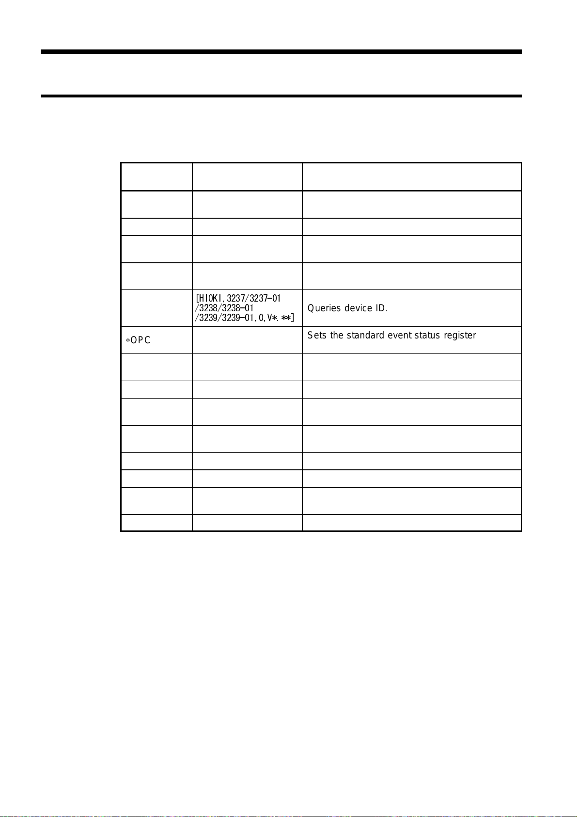
62
_____________________________________________________________________________________________
7.3 Command Code Table
7.3.1 Common Command
Message
∗CLS
∗ESE
∗ESE?
∗ESR?
∗IDN?
∗OPC
∗OPC?
∗RST
∗SRE
∗SRE?
Input/output
data format
Clears the status byte register and the event
registers.
NR1 numerical data (1) Sets the standard event status enable register.
NR1 numerical data (1)
NR1 numerical data (1)
[HIOKI,3237/3237-01
/3238/3238-01
/3239/3239-01,0,V*.**]
NR1 numerical data (1)
NR1 numerical data (1)
NR1 numerical data (1)
Read the standard event status enable register
(SESER).
Queries out and clears the contents of the
standard event status register (SESR).
Queries device ID.
Sets the standard event status register bit0
(OPC bit) to "1."
Returns a "1" instead of setting the SESR bit0
(OPC bit) to "1."
Initializes the settings.
Sets the service request enable register
(SRER).
Queries the service request enable register
(SRER).
Meaning
∗STB?
∗TRG
∗TST?
∗WAI
NR1 numerical data (1)
NR1 numerical data (1)
Queries
Request for sampling.
Requests execution of, and queries the result of,
the self test.
Waits until previous event is completed.
the status byte register.
( ) indicates the number of data.
______________________________________________________________________________________________
7.3 Command Code Table
_____________________________________________________________________________________________
63
7.3.2 Specific Command
Set and inquiry concerning event status register
Command Input/output data format Initial value
:ESE0 NR1 numerical data (1) 255
:ESE0? NR1 numerical data (1)
:ESR? NR1 numerical data (1)
Select and inquiry concerning measurement function
Command Input/output data format Initial value
[:SENSe:]FUNCtion 'VOLTage[:DC]'/'VOLTage:AC'/
'CURRent:DC'/'CURRent:AC'/
'RESistance'/'LPResistance'/
'FRESistance'/'LPFResistance'/
'CLAMp:DC'/'CLAMp:AC'/'FREQuency'/
'CONTinuity'/'DIODe'
[:SENSe:]FUNCtion? 'VOLTAGE[:DC]'/'VOLTAGE:AC'/
'CURRENT:DC'/'CURRENT:AC'/
'RESISTANCE'/'LPRESISTANCE'/
'FRESISTANCE'/'LPFRESISTANCE'/
'CLAMP:DC'/'CLAMP:AC'/'FREQUENCY'/
'CONTINUITY'/'DIODE'
'VOLT:DC'
Set and inquiry concerning range
Command Input/output data format Initial value
[:SENSe:]VOLTage[:DC]:RANGe NRf numerical data 199.999E-03
[:SENSe:]VOLTage[:DC]:RANGe? NR3 numerical data
[:SENSe:]VOLTage:AC:RANGe NRf numerical data 1.99999
[:SENSe:]VOLTage:AC:RANGe? NR3 numerical data
[:SENSe:]CURRent:DC:RANGe NRf numerical data 199.999E-03
[:SENSe:]CURRent:DC:RANGe? NR3 numerical data
[:SENSe:]CURRent:AC:RANGe NRf numerical data 199.999E-03
[:SENSe:]CURRent:AC:RANGe? NR3 numerical data
[:SENSe:]RESistance:RANGe NRf numerical data 199.999
[:SENSe:]RESistance:RANGe? NR3 numerical data
[:SENSe:]FRESistance:RANGe NRf numerical data 199.999
[:SENSe:]FRESistance:RANGe? NR3 numerical data
[:SENSe:]LPResistance:RANGe NRf numerical data 1.99999E+03
[:SENSe:]LPResistance:RANGe? NR3 numerical data
[:SENSe:]LPFResistance:RANGe NRf numerical data 1.99999E+03
[:SENSe:]LPFResistance:RANGe? NR3 numerical data
[:SENSe:]CLAMp:DC:RANGe NRf numerical data
[:SENSe:]CLAMp:DC:RANGe? NR3 numerical data
[:SENSe:]CLAMp:AC:RANGe NRf numerical data 10
[:SENSe:]CLAMp:AC:RANGe? NR3 numerical data
Set and inquiry concerning attenuator range (Frequency measurement)
Command Input/output data format Initial value
[:SENSe:]FREQuency:VOLTage:RANGe NRf numerical data 1.99999
[:SENSe:]FREQuency:VOLTage:RANGe? NR3 numerical data
______________________________________________________________________________________________
7.3 Command Code Table

64
_____________________________________________________________________________________________
Set and inquiry concerning Auto Range
Command Input/output data format Initial value
[:SENSe:]VOLTage[:DC]:RANGe:AUTO ON/OFF or 1/0 ON
[:SENSe:]VOLTage[:DC]:RANGe:AUTO? ON/OFF
[:SENSe:]VOLTage:AC:RANGe:AUTO ON/OFF or 1/0 ON
[:SENSe:]VOLTage:AC:RANGe:AUTO? ON/OFF
[:SENSe:]CURRent:DC:RANGe:AUTO ON/OFF or 1/0 ON
[:SENSe:]CURRent:DC:RANGe:AUTO? ON/OFF
[:SENSe:]CURRent:AC:RANGe:AUTO ON/OFF or 1/0 ON
[:SENSe:]CURRent:AC:RANGe:AUTO? ON/OFF
[:SENSe:]RESistance:RANGe:AUTO ON/OFF or 1/0 ON
[:SENSe:]RESistance:RANGe:AUTO? ON/OFF
[:SENSe:]LPResistance:RANGe:AUTO ON/OFF or 1/0 ON
[:SENSe:]LPResistance:RANGe:AUTO? ON/OFF
[:SENSe:]FRESistance:RANGe:AUTO ON/OFF or 1/0 ON
[:SENSe:]FRESistance:RANGe:AUTO? ON/OFF
[:SENSe:]LPFResistance:RANGe:AUTO ON/OFF or 1/0 ON
[:SENSe:]LPFResistance:RANGe:AUTO? ON/OFF
Set and inquiry concerning clamp sensor
Command Input/output data format Initial value
[:SENSe:]CLAMp:MODel NRf numerical data 9010
[:SENSe:]CLAMp:MODel? NR1 numerical data
Set and inquiry concerning the Zero-Adjusted value.
Command Input/output data format Initial value
[:SENSe:]VOLTage[:DC]:REFerence NRf numerical data 0
[:SENSe:]VOLTage[:DC]:REFerence? NR3 numerical data
[:SENSe:]VOLTage:AC:REFerence NRf numerical data 0
[:SENSe:]VOLTage:AC:REFerence? NR3 numerical data
[:SENSe:]CURRent:DC:REFerence NRf numerical data 0
[:SENSe:]CURRent:DC:REFerence? NR3 numerical data
[:SENSe:]CURRent:AC:REFerence NRf numerical data 0
[:SENSe:]CURRent:AC:REFerence? NR3 numerical data
[:SENSe:]RESistance:REFerence NRf numerical data 0
[:SENSe:]RESistance:REFerence? NR3 numerical data
[:SENSe:]LPResistance:REFerence NRf numerical data 0
[:SENSe:]LPResistance:REFerence? NR3 numerical data
[:SENSe:]FRESistance:REFerence NRf numerical data 0
[:SENSe:]FRESistance:REFerence? NR3 numerical data
[:SENSe:]LPFResistance:REFerence NRf numerical data 0
[:SENSe:]LPFResistance:REFerence? NR3 numerical data
[:SENSe:]CLAMp:DC:REFerence NRf numerical data 0
[:SENSe:]CLAMp:DC:REFerence? NR3 numerical data
[:SENSe:]CLAMp:AC:REFerence NRf numerical data 0
[:SENSe:]CLAMp:AC:REFerence? NR3 numerical data
______________________________________________________________________________________________
7.3 Command Code Table
_____________________________________________________________________________________________
65
Set and inquiry concerning Zero-Adjust execution
Command Input/output data format Initial value
[:SENSe:]VOLTage[:DC]:REFerence:STATe ON/OFF or 1/0 OFF
[:SENSe:]VOLTage[:DC]:REFerence:STATe? ON/OFF
[:SENSe:]VOLTage:AC:REFerence:STATe ON/OFF or 1/0 OFF
[:SENSe:]VOLTage:AC:REFerence:STATe? ON/OFF
[:SENSe:]CURRent:DC:REFerence:STATe ON/OFF or 1/0 OFF
[:SENSe:]CURRent:DC:REFerence:STATe? ON/OFF
[:SENSe:]CURRent:AC:REFerence:STATe ON/OFF or 1/0 OFF
[:SENSe:]CURRent:AC:REFerence:STATe? ON/OFF
[:SENSe:]RESistance:REFerence:STATe ON/OFF or 1/0 OFF
[:SENSe:]RESistance:REFerence:STATe? ON/OFF
[:SENSe:]LPResistance:REFerence:STATe ON/OFF or 1/0 OFF
[:SENSe:]LPResistance:REFerence:STATe? ON/OFF
[:SENSe:]FRESistance:REFerence:STATe ON/OFF or 1/0 OFF
[:SENSe:]FRESistance:REFerence:STATe? ON/OFF
[:SENSe:]LPFResistance:REFerence:STATe ON/OFF or 1/0 OFF
[:SENSe:]LPFResistance:REFerence:STATe? ON/OFF
[:SENSe:]CLAMp:DC:REFerence:STATe ON/OFF or 1/0 OFF
[:SENSe:]CLAMp:DC:REFerence:STATe? ON/OFF
[:SENSe:]CLAMp:AC:REFerence:STATe ON/OFF or 1/0 OFF
[:SENSe:]CLAMp:AC:REFerence:STATe? ON/OFF
Set and inquiry concerning sampling period
Command Input/output data format Initial value
:SAMPle:RATE FAST/MEDium/SLOW SLOW
:SAMPle:RATE? FAST/MEDIUM/SLOW
Set and inquiry concerning average function
Command Input/output data format Initial value
:CALCulate:AVERage NRf numerical data (2 to 100) 2
:CALCulate:AVERage? NR1 numerical data
:CALCulate:AVERage:STATe ON/OFF or 1/0 OFF
:CALCulate:AVERage:STATe? ON/OFF
Set and inquiry concerning comparator buzzer sound
Command Input/output data format Initial value
:CALCulate:LIMit:BEEPer OFF/IN/FAIL/HL HL
:CALCulate:LIMit:BEEPer? OFF/IN/HL
Set and inquiry concerning the comparator upper-limit value
Command Input/output data format Initial value
:CALCulate:LIMit:UPPer NRf numerical data 0
:CALCulate:LIMit:UPPer? NR1 numerical data
______________________________________________________________________________________________
7.3 Command Code Table

66
_____________________________________________________________________________________________
Set and inquiry concerning comparator lower-limit value
Command Input/output data format Initial value
:CALCulate:LIMit:LOWer NRf numerical data 0
:CALCulate:LIMit:LOWer? NR1 numerical data
Set and inquiry concerning comparator execution
Command Input/output data format Initial value
:CALCulate:LIMit:STATe ON/OFF or 1/0 OFF
:CALCulate:LIMit:STATe? ON/OFF
Inquiry concerning comparator determination
Command Input/output data format Initial value
:CALCulate:LIMit:FAIL? HI/IN/LO/OFF/ERROR
Set and inquiry concerning key operation sound
Command Input/output data format Initial value
:SYSTem:BEEPer:STATe ON/OFF or 1/0 ON
:SYSTem:BEEPer:STATe? ON/OFF
Set and inquiry concerning power-supply frequency
Command Input/output data format Initial value
:SYSTem:LFRequency 50/60 60
:SYSTem:LFRequency? 50/60
Set and inquiry concerning Key Lock
Command Input/output data format Initial value
:SYSTem:KLOCk ON/OFF or 1/0 OFF
:SYSTem:KLOCk? ON/OFF
Panel Save and Panel Load
Command Input/output data format Initial value
:SYSTem:SAVe NRf numerical data
:SYSTem:LOAD NRf numerical data
Set and inquiry concerning Format
Command Input/output data format Initial value
:SYSTem:FORMat NR1 numerical data 1
:SYSTem:FORMat? 1/2
Set and inquiry concerning header On/Off
Command Input/output data format Initial value
:SYSTem:HEADer ON/OFF or 1/0 OFF
:SYSTem:HEADer? ON/OFF
______________________________________________________________________________________________
7.3 Command Code Table
_____________________________________________________________________________________________
67
Set and inquiry concerning delimiter
Command Input/output data format Initial value
:SYSTem:TERMinator NR1 numerical data 1
:SYSTem:TERMinator? 0/1 (0: LF, 1: CR+LF)
Set and inquiry concerning Continuous Trigger state
Command Input/output data format Initial value
:INITiate:CONTinuous ON/OFF or 1/0 ON
:INITiate:CONTinuous? ON/OFF
Setup of Trigger Wait state
Command Input/output data format Initial value
:INITiate[:IMMediate] Command
Set and inquiry concerning trigger source
Command Input/output data format Initial value
:TRIGger:SOURce IMMediate/EXTernal IMM
:TRIGger:SOURce? IMMediate/EXTernal
Last measurement-value read-out
Command Input/output data format Initial value
:FETCh? NR3 numerical data
Measurements (Await Trigger and Measurement-Value Read-out)
Command Input/output data format Initial value
:READ? NR3 numerical data
Set and inquiry concerning trigger delay time
Command Input/output data format Initial value
:TRIGger:DELay NRf numerical data 0
:TRIGger:DELay? NR3 numerical data
Set and inquiry concerning Auto Trigger Delay
Command Input/output data format Initial value
:TRIGger:DELay:AUTO ON/OFF or 1/0 ON
:TRIGger:DELay:AUTO? ON/OFF
______________________________________________________________________________________________
7.3 Command Code Table

68
_____________________________________________________________________________________________
Presetting of Ranges and Functions
Command Input/output data format Initial value
:CONFigure:VOLTage[:DC]? NRf numerical data
:CONFigure:VOLTage:AC? NRf numerical data
:CONFigure:CURRent:DC? NRf numerical data
:CONFigure:CURRent:AC? NRf numerical data
:CONFigure:RESistance? NRf numerical data
:CONFigure:LPResistance? NRf numerical data
:CONFigure:FRESistance? NRf numerical data
:CONFigure:LPFResistance? NRf numerical data
:CONFigure:CLAMp:DC? NRf numerical data
:CONFigure:CLAMp:AC? NRf numerical data
:CONFigure:FREQuency? NRf numerical data
:CONFigure:DIODe? NRf numerical data
Inquiry concerning preset functions
Command Input/output data format Initial value
:CONFigure? VOLTAGE:DC/
VOLTAGE:AC/CURRENT:DC/
CURRENT:AC/RESISTANCE/
LPRESISTANCE/FRESISTANCE/
LPFRESISTANCE/FREQUENCY/
CONTINUITY/DIODE/CLAMP:DC/
CLAMP:AC
Measurement with a Specified Range and Function Preset
Command Input/output data format Initial value
:MEASure:VOLTage[:DC]? NRf numerical data
:MEASure:VOLTage:AC? NRf numerical data
:MEASure:CURRent:DC? NRf numerical data
:MEASure:CURRent:AC? NRf numerical data
:MEASure:RESistance? NRf numerical data
:MEASure:LPResistance? NRf numerical data
:MEASure:FRESistance? NRf numerical data
:MEASure:LPFResistance? NRf numerical data
:MEASure:CLAMp:DC? NRf numerical data
:MEASure:CLAMp:AC? NRf numerical data
:MEASure:FREQuency? NRf numerical data
:MEASure:DIODe? NRf numerical data
______________________________________________________________________________________________
7.3 Command Code Table

_____________________________________________________________________________________________
69
7.4 Command Reference
7.4.1 Explanation of Command Reference
Command
Indicates functions of command reference
Syntax
data
Function
Note
Response
syntax
Example
Indicates the command syntax.
Indicates the data format for a command that includes data.
Describes points that require special attention when using the command.
Indicates the what kinds of errors might occur.
Indicated only for commands for which a response message is returned.
Shows a simple example illustrating tran smissions are indicated in "short form."
NOTE
The syntax items indicated between brackets [ ] in the command reference may be omitted.
______________________________________________________________________________________________
7.4 Command Reference

70
_____________________________________________________________________________________________
7.4.2 Common Command Messages
∗CLS command
Clears the status byte register and the event registers.
Syntax
Function
Note
∗CLS
This instruction clears the event r egisters and the bits of the status byte register associated with that
register (SESR, STB).
This has no effect upon the output queue, the various enable registers, or bit 4 (the MAV bit) of the
status byte register.
∗ESE command
Sets the standard event status enable register.
Syntax
data
Function
Note
Example
∗ESE data
NR1 numerical data numerical data
0 to 255
This command sets the available patterns of the standard event status register (SESR) to the
standard event status enable register (SESER).
When the power is turned on, the data is reinitialized to 0.
Transmission ∗ESE 36
CME and QYE of the standard event status enable register are both set to "1."
bit7 bit6 bit5 bit4 bit3 bit2 bit1 bit0
PON URQ CME EXE DDE QYE RQC OPC
Standard event status enable resister (SESER)
∗ESE? command
Read the standard event status enable register (SESER).
Syntax
Function
Response
syntax
Example
∗ESE?
The contents of SESER are returned as a NR1 numerical data value (0 to 255).
Headers: ON ∗ESE data
Headers: OFF data
Headers: OFF
Transmission ∗ESE?
Response 36
______________________________________________________________________________________________
7.4 Command Reference

_____________________________________________________________________________________________
71
∗ESR? command
Queries out and clears the contents of the standard event status register (SESR).
Syntax
Function
Response
syntax
Example
∗ESR?
This command returns the contents of the standard event status register (SESR) in NR1 numerical
data format (data) (ranging from 0 to 255), then clears the register.
Headers: ON ∗ESR data
Headers: OFF data
Headers: OFF
Transmission ∗ESE?
Response 36
∗IDN? command
Queries device ID.
Syntax
Function
Note
Response
syntax
∗IDN?
Queries device ID (manufacturer's name, model name, software version.
The ∗IDN? query is the last query message of the program messages. No further response is output.
HIOKI,3237,0,V2.00
First field Manufacturer's name
Second field Model name
Third field Not used - always "0"
Fourth field Software version
Example
Headers: ON
Transmission ∗IDN?
Response ∗IDN HIOKI,3237,0,V2.00
Headers: OFF
Transmission ∗IDN?
Response HIOKI,3237,0,V2.00
∗OPC command
Sets the standard event status register bit0 (OPC bit) to "1."
Syntax
Function
Example
∗OPC
This command sets the standard event status register (SESR) bit0 (OPC bit) to "1" when all actions
specified by messages and occurring before the ∗OPC command are complete.
Transmission ∗RST;:MEAS:RES?;∗OPC
This command sets the specified bit to "1" when all ∗RST and MEAS actions
are complete.
______________________________________________________________________________________________
7.4 Command Reference

72
_____________________________________________________________________________________________
∗OPC? command
Returns a "1" instead of setting the SESR bit0 (OPC bit) to "1."
Syntax
Function
Response
syntax
Example
∗OPC?
The same as the ∗OPC command, except in that, at the instant t hat the previous commands have
been completed, instead of bit 0 (the OPC bit) of the standard event status register (SESR) being
set to 1, the response message "1" is returned.
Headers: ON ∗OPC 1
Headers: OFF 1
Transmission ∗RST;:MEAS:RES?;∗OPC?
Returns a "1" when all ∗RST and MEAS actions are complete.
∗RST command
Initializes the settings.
Syntax
Function
Note
∗RST
Resets and initialize s the main unit.
For initialized data, refer to 5.8 System Reset.
If any data follows the command, a command error is generated.
Data not affected by the initialization
Status byte register, Standard event status register, Enable registers, Interface function, GPIB address, Output queue, Input buffer, Current pass
∗SRE command
Sets the service request enable register (SRER).
Syntax
data
Function
Note
Example
∗SRE data
NR1 numerical data
0 to 255
This command sets the available patterns of the service request enable resister (SRER) to the status
byte register (STB).
When 3237/38/39 is turned on or I/F is switched, the data is reset to "0."
Bit 6 is set to 0.
Transmission ∗SRE 32
Explanation of example: the service request enable register ESB is set to
"1."
______________________________________________________________________________________________
7.4 Command Reference

_____________________________________________________________________________________________
73
∗SRE? command
Queries the service request enable register (SRER).
Syntax
Function
Response
syntax
Example
∗SRE?
Returns the value of the service request enable register (SRER) set by the ∗SRE command as a
numerical data value in NR1 format taken from the set: 0 to 255.
Headers: ON SRE data
Headers: OFF data
Transmission ∗SRE?
Response 32
∗STB? command
Queries
the status byte register.
Syntax
Function
Note
Example
∗STB?
Returns the set contents of the status byte register (STB) as a numerical data value in NR1 format
(0,16,32,48).
The value in the MSS bit represents bit6. The MSS bit remains uncleared, even if the service
request is cleared by the serial poll.
Transmission ∗STB?
Response 32
∗TRG command
Request for sampling
Syntax
Function
∗TRG
This command executes one sampling cycle while the 3237/38/39 is in Trigger Wait state.
______________________________________________________________________________________________
7.4 Command Reference

74
_____________________________________________________________________________________________
∗TST? command
Requests execution of, and queries the result of, the self test.
Syntax
Function
Response
syntax
Example
∗TST?
Causes the 3237/38/39 to perform the self test, and returns the result there of as a numerical data
value in NR1 format (0 to 7).
The results are shown below. When each bit is set to "1," an asso ciated error has occurred.
Headers: ON ∗TST data
Headers: OFF data
Headers: OFF
Transmission ∗TST?
Response 2
RAM error
bit7 bit6 bit5 bit4 bit3 bit2 bit1 bit0
Not used Not used Not used Not used Not used Not used
∗WAI command
Waits until previous event is completed.
Syntax
Function
∗WAI
The next command executes after the command now executing.
RAM ROM
Note
Executing the ∗WAI command has no effect, since the 3237/38/39 specific commands all involve
sequential-type commands.
The ∗WAI command is accepted, since it is a common command for the
IEEE488.2 1987 standard.
______________________________________________________________________________________________
7.4 Command Reference

_____________________________________________________________________________________________
75
7.4.3 Specific Command Messages
Event Status Register 0
Sets the event status enable register 0.
Syntax
data
Function
Note
:ESE data
NR1 numerical data numerical data
0 to 255
This command sets the available patterns of the standard event status register (SESR) to the event
status enable register 0 (ESER0).
When the power is turned on, the data is reinitialized to 0.
bit7 bit6 bit5 bit4 bit3 bit2 bit1 bit0
Not used Not used
-OF +OF HI IN LO EOC
Event status enable resister 0 (ESER0)
Read the event status enable register 0.
Syntax
Function
:ESE?
The contents of ESER0 are returned as a NR1 numerical data value (0 to 255).
Read the event status register 0.
Syntax
Function
:ESR0?
This command returns the contents of the event status register 0 (ESR0) in NR1 numerical data
format (data) (ranging from 0 to 255), then clears the register.
______________________________________________________________________________________________
7.4 Command Reference

76
_____________________________________________________________________________________________
Measurement Composition Command
Selection of measurement functions
Syntax
data
Function
Note
Example
[:SENSe:]FUNCtion data
Character data
'VOLTage[:DC]' DC voltage measurement
'VOLTage:AC' AC voltage measurement
'CURRent:DC' DC current measurement
'CURRent:AC' AC current measurement
'RESistance' 2-terminal resistance measurement
'LPResistance' Low-power 2-terminal resistance measurement
'FRESistance' 4-terminal resistance measurement
'LPRFesistance' Low-power 4-terminal resistance measurement
'CLAMp:DC' DC clamp current measurement
'CLAMp:AC' AC clamp current measurement
'FREQuency' Frequency measurement
'CONTinuity' Continuity test
'DIODe' Diode test
Selects a measurement function.
data must be enclosed in single quot ation marks.
[:SENSe:] may be omitted.
Transmission FUNC 'VOLT:DC'
Sets the DC voltage measurement function.
Inquiry concerning measurement function
Syntax
data
Function
Response
syntax
Example
[:SENSe:]FUNCtion?
Character data
'VOLTAGE:DC','VOLTAGE:AC','CURRENT:DC','CURRENT:AC','RESISTANCE',
'LPRESISTANCE','FRESISTANCE','LPRFESISTANCE','CLAMP:DC','CLAMP:AC',
'FREQUENCY','CONTINUITY','DIODE'
Returns the currently set measurement function in a character string enclosed in single quotation
marks.
Headers: ON :SENSE:FUNCTION data
Headers: OFF data
Headers: ON
Transmission :SENS:FUNC?
Response :SENSE:FUNCTION 'RESISTANCE'
Headers: OFF
Transmission :SENS:FUNC?
Response 'RESISTANCE'
______________________________________________________________________________________________
7.4 Command Reference

_____________________________________________________________________________________________
77
Range setup
Syntax
data
Function
Note
Example
[:SENSe:]VOLTage[:DC]:RANGe data
[:SENSe:]VOLTage:AC:RANGe data
[:SENSe:]CURRent:DC:RANGe data
[:SENSe:]CURRent:AC:RANGe data
[:SENSe:]RESistance:RANGe data
[:SENSe:]LPResistance:RANGe data
[:SENSe:]FRESistance:RANGe data
[:SENSe:]LPFResistance:RANGe data
[:SENSe:]CLAMp:DC:RANGe data
[:SENSe:]CLAMp:AC:RANGe data
[:SENSe:]FREQuency:VOLTage:RANGe data
NRf numerical data
Input the expected measurement value. The unit automatically selects the optimum range for
measuring the given entered value.
Sets a range for the selected measurement function.
Any attempt to set a range outside measurement range for the specified measurement function
will result in an execution error.
In the case of the frequency measurement function, the range set is for input voltages (attenuator
range), not frequencies.
Transmission :SENS:VOLT:DC:RANGe -300
Sets the DC voltage measurement function to the 1000 V range.
RES:RANG 800
Sets the resistance measurement function to the 2000 Ω range.
:SENS:FREQ:VOLT:RANG 1.5
Sets the attenuator range to the 2 V range in a frequency measurement.
Inquiry concerning range
Syntax
data
Function
Response
syntax
Example
[:SENSe:]VOLTage[:DC]:RANGe?
[:SENSe:]VOLTage:AC:RANGe?
[:SENSe:]CURRent:DC:RANGe?
[:SENSe:]CURRent:AC:RANGe?
[:SENSe:]RESistance:RANGe?
[:SENSe:]LPResistance:RANGe?
[:SENSe:]FRESistance:RANGe?
[:SENSe:]LPFResistance:RANGe?
[:SENSe:]CLAMp:DC:RANGe?
[:SENSe:]CLAMp:AC:RANGe?
[:SENSe:]FREQuency:VOLTage:RANGe?
NR3 numerical data
Inquires about the range of the specified measurement function.
Headers: ON :SENSE:LPRESISTANCE:RANGE data
Headers: OFF data
Headers: ON
Transmission CURR:AC:RANG?
Response :SENSE:CURRENT:AC:RANGE 199.999E-03
Headers: OFF
Transmission CURR:AC:RANG?
Response 199.999E-03
The AC current measurement range is 200 mA.
______________________________________________________________________________________________
7.4 Command Reference

78
_____________________________________________________________________________________________
Setup for Auto Range
Syntax
data
Function
Example
[:SENSe:]VOLTage[:DC]:RANGe:AUTO
[:SENSe:]VOLTage:AC:RANGe:AUTO
[:SENSe:]CURRent:DC:RANGe:AUTO
[:SENSe:]CURRent:AC:RANGe:AUTO
[:SENSe:]RESistance:RANGe:AUTO
[:SENSe:]LPResistance:RANGe:AUTO
[:SENSe:]FRESistance:RANGe:AUTO
[:SENSe:]LPFResistance:RANGe:AUTO
ON/1: Auto Range enabled.
OFF/0: Auto Range disabled.
Selects to enable or disable Auto Range of th specified measurement function.
Transmission :SENSE:VOLT:AC:RANG:AUTO ON
VOLT:AC:RANG:AUTO 0
Inquiry concerning Auto Range
Syntax
[:SENSe:]VOLTage[:DC]:RANGe:AUTO?
[:SENSe:]VOLTage:AC:RANGe:AUTO?
[:SENSe:]CURRent:DC:RANGe:AUTO?
[:SENSe:]CURRent:AC:RANGe:AUTO?
[:SENSe:]RESistance:RANGe:AUTO?
[:SENSe:]LPResistance:RANGe:AUTO?
[:SENSe:]FRESistance:RANGe:AUTO?
[:SENSe:]LPFResistance:RANGe:AUTO?
data
Function
Response
syntax
Example
Character data
ON/OFF
Inquires whether the specified measurement function is set in Auto Range or not.
Headers: ON :SENSE:CURRENT:DC:RANGE:AUTO data
Headers: OFF data
Headers: ON
Transmission RES:RANG:AUTO?
Response :SENSE:RESISTANCE:RANGE:AUTO ON
Headers: OFF
Transmission RES:RANG:AUTO?
Response ON
The resistance measurement function is in Auto Range.
______________________________________________________________________________________________
7.4 Command Reference

_____________________________________________________________________________________________
79
Setup for clamp sensor
Syntax
data
Function
Example
[:SENSe:]CLAMp:MODel data
NRf numerical data
9010,9132,9018,3283,9 270, 9271,9272,9277,9278,9279,3284,3285
Selects the clamp sensor to be used in clamp current measurement.
Transmission CLAM:MOD 9132
Inquiry concerning clamp sensor
Syntax
data
Function
Response
syntax
[:SENSe:]CLAMp:MODel?
NR1 numerical data
Inquires about the model of the clamp sensor currently set.
Headers: ON :SENSE:CLAMP:MODEL data
Headers: OFF data
Setup for Zero-Adjusted value
Syntax
[:SENSe:]VOLTage[:DC]:REFerence data
[:SENSe:]VOLTage:AC:REFerence data
[:SENSe:]CURRent:DC:REFerence data
[:SENSe:]CURRent:AC:REFerence data
[:SENSe:]RESistance:REFerence data
[:SENSe:]LPResistance:REFerence data
[:SENSe:]FRESistance:REFerence data
[:SENSe:]LPFResistance:REFerence data
[:SENSe:]CLAMp:DC:REFerence data
[:SENSe:]CLAMp:AC:REFerence data
[:SENSe:]FREQuency:REFerence data
data
Function
Note
Example
NRf numerical data
Sets the Zero-Adjsted value. When the Zero-Adjust function is active, the unit returns a
measurement value obtained by subtracting the Zero-Adjusted value.
If the NRf numerical value data is set to a value larger than the maximum value (minimum value, if
negative) that can be measured with each function, an execution error will be issued.
Transmission VOLT:REF 13.63
Sets 13.63 V as the Zero-Adjusted value of the DC voltage measurement
function. When the Zero-Adjust function is active, the unit outputs a value that
results from subtracting 13.63 V as the measurement value.
______________________________________________________________________________________________
7.4 Command Reference

80
_____________________________________________________________________________________________
Inquiry concerning the Zero-Adjusted value.
Syntax
data
Function
Response
syntax
Example
[:SENSe:]VOLTage[:DC]:REFerence?
[:SENSe:]VOLTage:AC:REFerence?
[:SENSe:]CURRent:DC:REFerence?
[:SENSe:]CURRent:AC:REFerence?
[:SENSe:]RESistance:REFerence?
[:SENSe:]LPResistance:REFerence?
[:SENSe:]FRESistance:REFerence?
[:SENSe:]LPFResistance:REFerence?
[:SENSe:]CLAMp:DC:REFerence?
[:SENSe:]CLAMp:AC:REFerence?
[:SENSe:]FREQuency:REFerence?
NR3 numerical data
Inquires about the Zero-Adjusted value.
Headers: ON :SENSE:VOLTAGE:AC:REFERENCE data
Headers: OFF data
Headers: ON
Transmission CURR:DC:REF?
Response :SENSE:CURRENT:DC:REFERENCE 6.320000E-02
Headers: OFF
Transmission CURR:DC:REF?
Response 6.320000E-02
The Zero-Adjusted value in a DC current measurement is 63.2 mA.
Setup for Zero-Adjust execution
Syntax
data
Function
Example
[:SENSe:]VOLTage[:DC]:REFerence:STATe data
[:SENSe:]VOLTage:AC:REFerenceSTATe data
[:SENSe:]CURRent:DC:REFerence:STATe data
[:SENSe:]CURRent:AC:REFerence:STATe data
[:SENSe:]RESistance:REFerence:STATe data
[:SENSe:]LPResistance:REFerence:STATe data
[:SENSe:]FRESistance:REFerence:STATe data
[:SENSe:]LPFResistance:REFerence:STATe data
[:SENSe:]CLAMp:DC:REFerence:STATe data
[:SENSe:]CLAMp:AC:REFerence:STATe data
[:SENSe:]FREQuency:REFerence:STATe data
ON/1: Zero-Adjust function enabled.
OFF/0: Zero-Adjust function disabled.
Selects whether the Zero-Adjusted value set for the specified measurement function is to be
subtracted or not.
Transmission :SENS:CURR:AC:REF:STAT 1
Enables the Zero-Adjust function of the AC current measurement function.
RES:REF:STAT OFF
Disables the Zero-Adjust function of the resistance measurement function.
______________________________________________________________________________________________
7.4 Command Reference

_____________________________________________________________________________________________
81
Inquiry concerning Zero-Adjust execution
Syntax
data
Function
Response
syntax
Example
[:SENSe:]VOLTage[:DC]:REFerence:STATe?
[:SENSe:]VOLTage:AC:REFerence:STATe?
[:SENSe:]CURRent:DC:REFerence:STATe?
[:SENSe:]CURRent:AC:REFerence:STATe?
[:SENSe:]RESistance:REFerence:STATe?
[:SENSe:]LPResistance:REFerence:STATe?
[:SENSe:]FRESistance:REFerence:STATe?
[:SENSe:]LPFResistance:REFerence:STATe?
[:SENSe:]CLAMp:DC:REFerence:STATe?
[:SENSe:]CLAMp:AC:REFerence:STATe?
[:SENSe:]FREQuency:REFerence:STATe?
Character data
ON/OFF
Inquires whether the Zero-Adjust function of the specified measurement function is enabled or
disabled.
Headers: ON :SENSE:LPRESISTANCE:REFERENCE:STATE data
Headers: OFF data
Headers: ON
Transmission FREQ:REF:STAT?
Response :SENSE:FREQUENCY:REFERENCE:STATE OFF
Headers: OFF
Transmission FREQ:REF:STAT?
Response OFF
The Zero-Adjust function of the frequency measurement function is disabled.
______________________________________________________________________________________________
7.4 Command Reference

82
_____________________________________________________________________________________________
SamplingCommands
Setup for sampling period
Syntax
data
Function
Example
:SAMPle:RATE data
Chatacter data
FAST,MEDium,SLOW
Switches the sampling period.
Transmission SAMPle:RATE MED
Sets the sampling period to MEDIUM.
Inquiry concerning sampling period
Syntax
data
Function
Response
syntax
Example
:SAMPle:RATE?
Character data
FAST,MEDIUM,SLOW
Inquires about the sampling period currently set.
Headers: ON :SAMPLE:RATE data
Headers: OFF data
Headers: ON
Transmission :SAMP:RATE?
Response :SAMPLE:RATE FAST
Headers: OFF
Transmission :SAMP:RATE?
Response FAST
The sampling period is FAST.
______________________________________________________________________________________________
7.4 Command Reference

_____________________________________________________________________________________________
83
ComputingFunction Commands
Setup for the number of averaged measurements
Syntax
data
Function
Example
:CALCulate:AVERage data
NRf numerical data
2 to 100
Sets a number of averaged measurements.
Transmission :CALC:AVER 10
Sets the number of averaged measurements to 10.
Inquiry concerning the number of averaged measurements
Syntax
data
Function
Response
syntax
Example
:CALCulate:AVERage?
NR1 numerical data
2 to 100
Inquires about the number of averaged measurements currently set.
Headers: ON :CALCULATE:AVERAGE data
Headers: OFF data
Headers: ON
Transmission :CALC:AVER?
Response :CALCULATE:AVERAGE 10
Headers: OFF
Transmission :CALC:AVER?
Response 10
The number of averaged measurements is 10.
Setup for average execution
Syntax
data
Function
Example
:CALCulate:AVERage:STATe data
ON/1: Averaging function enabled
OFF/0: Averaging function disabled
Sets the average execution.
Transmission :CALC:AVER:STAT 1
Enables the averaging function.
Inquiry concerning average execution
Syntax
data
Function
Response
syntax
:CALCulate:AVERage:STATe?
Character data
ON/OFF
Inquires whether the averaging function is enabled or disabled.
Headers: ON :CALCULATE:AVERAGE:STATE data
Headers: OFF data
______________________________________________________________________________________________
7.4 Command Reference

84
_____________________________________________________________________________________________
Setup for comparator buzzer sound
Syntax
data
Function
Note
Example
:CALCulate:LIMit:BEEPer data
Character data
OFF,IN,FAIL,HL
Sets the buzzer sound to beep according to the comparator determination.
HL is the same as FAIL.
Transmission :CALC:LIM:BEEP IN
Activates the buzzer when the comparator determination is IN.
Inquiry concerning comparator buzzer sound
Syntax
data
Function
Response
syntax
Example
:CALCulate:LIMit:BEEPer?
Character data
OFF,IN,HL
Inquires about the setting that activates the buzzer at the comparator determination.
Headers: ON :CALCULATE:LIMIT:BEEPER data
Headers: OFF data
Headers: ON
Transmission :CALC:LIM:BEEP?
Response :CALCULATE:LIMIT:BEEPER FAIL
Headers: OFF
Transmission :CALC:LIM:BEEP?
Response FAIL
If the determination is FAIL (Hi, Lo), the buzzer beeps.
Setup for comparator upper-limit value
Syntax
data
Function
Note
Example
:CALCulate:LIMit:UPPer data
NRf numerical data
-199999 to 19999 9
Sets the upper-limit value to be used for comparator determination in a count value.
For example, if the upper-limit value is set to 123456 in the DC2 V range, the comparator
determines a Hi setting when the measurement value is greater than 1.23456 V.
Transmission :CALC:LIM:UPP 156000
Sets the comparator upper-limit value to 156000.
______________________________________________________________________________________________
7.4 Command Reference

_____________________________________________________________________________________________
85
Inquiry concerning the comparator upper-limit value
Syntax
data
Function
Response
syntax
Example
:CALCulate:LIMit:UPPer?
NR1 numerical data
-199999 to 19999 9
Inquires about the upper-limit value of the comparator.
Headers: ON :CALCULATE:LIMIT:UPPER data
Headers: OFF data
Headers: ON
Transmission :CALC:LIM:UPP?
Response :CALCULATE:LIMIT:UPPER 130000
Headers: OFF
Transmission :CALC:LIM:UPP?
Response 130000
The upper-limit value of the comparator is 130000.
Setup for comparator lower-limit value
Syntax
data
:CALCulate:LIMit:LOWer data
NRf numerical data
-199999 to 19999 9
Function
Example
Sets the lower-limit value to be used for comparator determination in a count value.
Transmission :CALC:LIM:LOW 145000
Sets the comparator lower-limit value to 145000.
Inquiry concerning comparator lower-limit value
Syntax
data
Function
Response
syntax
Example
:CALCulate:LIMit:LOWer?
NR1 numerical data
-199999 to 19999 9
Inquires about the lower-limit value of the comparator.
Headers: ON :CALCULATE:LIMIT:LOWER data
Headers: OFF data
Headers: ON
Transmission :CALC:LIM:LOW?
Response :CALCULATE:LIMIT:LOWER 120000
Headers: OFF
Transmission :CALC:LIM:LOW?
Response 120000
The lower-limit value of the comparator is 120000.
______________________________________________________________________________________________
7.4 Command Reference

86
_____________________________________________________________________________________________
Setup for comparator execution
Syntax
data
Function
Note
Example
:CALCulate:LIMit:STATe data
ON/1: Comparator function enabled
OFF/0: Comparator function disabled
Selects whether the comparator function is to be executed or not.
An execution error will be issued, if the comparator upper-limit value is smaller than the lower-limit
value.
Transmission :CALC:LIM:STAT ON
Executes the comparator.
Inquiry concerning comparator execution
Syntax
data
Function
Response
syntax
:CALCulate:LIMit:STATe?
Character data
ON/OFF
Inquires whether the comparator function is being executed or not.
Headers: ON :CALCULATE:LIMIT:STATE data
Headers: OFF data
Example
Headers: ON
Transmission :CALC:LIM:STAT?
Response :CALCULATE:LIMIT:STATE ON
Headers: OFF
Transmission :CALC:LIM:STAT?
Response ON
The comparator function is being executed.
Inquiry concerning comparator determination
Syntax
data
Function
Response
syntax
Example
:CALCulate:LIMit:FAIL?
IN: The measurement value is between the upper-limit and lower-limit values (IN).
HI: The measurement value is greater than the upper-limit value (Hi).
LO: The measurement value is smaller than the lower-limit value (Lo).
OFF: The comparator function is disabled.
:CALCULATE:LIMIT:STATE 0
ERROR: The comparator upper-limit value is set below its lower-limit value.
Inquires about the comparator determination.
Headers: ON CALCULATE:LIMIT:FAIL data
Headers: OFF data
Headers: ON
Transmission :CALC:LIM:FAIL?
Response :CALCULATE:LIMIT:FAIL IN
Headers: OFF
Transmission :CALC:LIM:FAIL?
Response IN
The comparator determination is IN.
______________________________________________________________________________________________
7.4 Command Reference

_____________________________________________________________________________________________
87
System-related Commands
Setup for key operation sound
Syntax
data
Function
Example
:SYSTem:BEEPer:STATe data
ON/1: Key operation sound enabled
OFF/0: Key operation sound disabled
Sets the key operation sound.
Transmission :SYST:BEEP:STAT 1
Key operation sound enabled.
Inquiry concerning key operation sound
Syntax
data
Function
Response
syntax
Example
:SYSTem:BEEPer:STATe?
Character data
ON/OFF
Inquires about the setting for the key operation sound.
Headers: ON :SYSTEM:BEEPER:STATE data
Headers: OFF data
Headers: ON
Transmission :SYST:BEEP:STAT?
Response :SYSTEM:BEEPER:STATE OFF
Headers: OFF
Transmission :SYST:BEEP:STAT?
Response OFF
Setup for power-supply frequency
Syntax
data
Function
Example
:SYSTem:LFRequency data
50: This is specified when the frequency of the power supplied to this unit is 50 Hz.
60: This is specified when the frequency of the power supplied to this unit is 60 Hz.
Specifies the frequency of the power supplied to this unit.
Transmission :SYST:LFR 50
Indicates to the main unit that the frequency of the power being supplied is
50 Hz.
______________________________________________________________________________________________
7.4 Command Reference

88
_____________________________________________________________________________________________
Inquiry concerning power-supply frequency
Syntax
data
Function
Response
syntax
Example
:SYSTem:LFRequency?
NR1 numerical data
50,60
Inquires about the setting for the power-supply frequency.
Headers: ON :SYSTEM:LFREQUENCY data
Headers: OFF data
Headers: ON
Transmission :SYST:LFR?
Response :SYSTEM:LFREQUENCY 60
Headers: OFF
Transmission :SYST:LFR?
Response 60
The power-supply frequency of the unit is set to 60 Hz.
Setup for Key Lock
Syntax
data
:SYSTem:KLOCk data
ON/1: Sets the Key Lock state.
OFF/0: Clears the Key Lock state.
Function
Example
Sets the Key Lock state.
Transmission :SYST:KLOC ON
Disables key operations on the front panel.
Inquiry concerning Key Lock
Syntax
data
Function
Response
syntax
Example
:SYSTem:KLOCk?
Character data
ON/OFF
Inquires about the state of Key Lock.
Headers: ON :SYSTEM:KLOCK data
Headers: OFF data
Headers: ON
Transmission :SYST:KLOC?
Response :SYSTEM:KLOCK ON
Headers: OFF
Transmission :SYST:KLOC?
Response ON
Key operations on the main unit are disabled.
______________________________________________________________________________________________
7.4 Command Reference
 Loading...