

Page 1

INSTRUCTION MANUA
L
For...は専用機種。複数の場合は「/」で区切る。不要の場合はとる
。
形名を入力。 複数の場合は「/」で区切る
。
322
7
品名を入力
。
mΩ HiTESTE
R
Page 2

Page 3

Contents
Introduction i
Inspection
i
Safety Notes
ii
Notes on Use
iv
Organization of this Manual
vi
Chapter 1 Overview
1
1.1 Features 1
1.2 Specifications 2
1.2.1 General Specifications 2
1.2.2 Resistance Measurement
4
1.2.3 Temperature Measurements
5
1.2.4 Temperature Correction Function
5
1.3 Measurements and Working Systems 6
1.3.1 4-terminal Measurements 6
1.3.2 Temperature Probe
7
1.3.3 Measurement Value Display
10
1.3.4 Comparator Function
12
Chapter 2 Part Names 15
2.1 Front Panel 15
2.2 Rear Panel 16
2.3 Displays
17
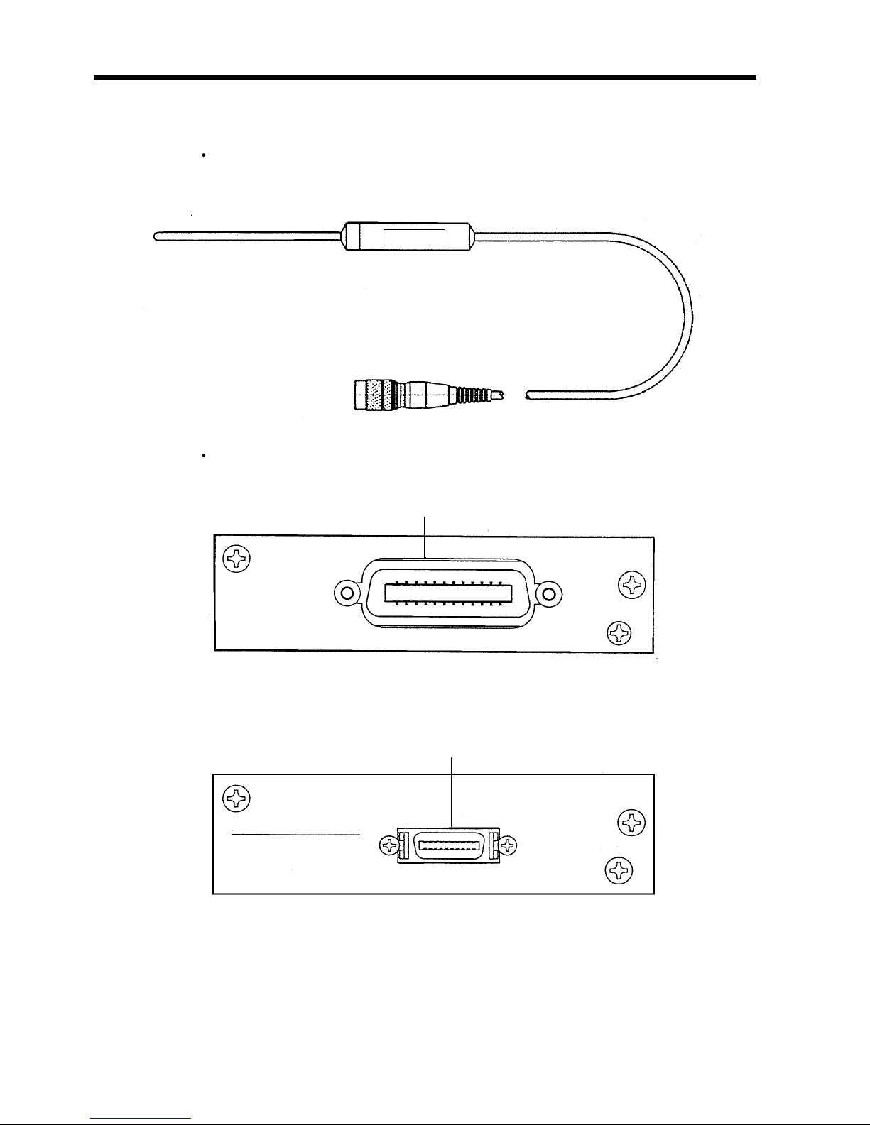
2.4 Accessory and Options
18
Chapter 3 Unit Installation 19
3.1 Installing the Interfaces 19
3.2 Turning on the Power Supply 21
3.3 Selecting the Power Supply Frequency 23
3.4 Preparation for Measurements 24
3.4.1 Resistance Measurements 24
3.4.2 Temperature Correction and Temperature Measurements
25
3.5 Handle Operation 26
Page 4

Chapter 4 Basic Operations 27
4.1 Operating Procedure 27
4.1.1 Function Classes 27
4.1.2 Key Shift States
28
4.1.3 Key Lock State
28
4.1.4 Remote State
28
4.1.5 Valid Input Key Table
29
4.2 Selecting the Measurement Mode 30
4.3 Resistance Measurement Mode 31
4.3.1 Selecting the Sampling Rate 31
4.3.2 Selecting the Measuring Range
32
4.3.3 Zero Adjustment
34
4.4 Resistance Measurement 35
4.5 Temperature Measurement
36
4.6 Holding the Measurement Value
37
Chapter 5 Applied Operations 39
5.1 Setting the Comparator 39
5.1.1 Setting the Comparator 1 39
5.1.2 Setting the Comparator 2
41
5.1.3 Eliminating the Comparator Table
42
5.2 Executing the Comparator 43
5.3 Setting the Temperature Correction
44
5.4 Executing the Temperature Correction
45
5.5 Setting the Temperature Conversion 46
5.6 Executing the Temperature Conversion 47
Chapter 6 External Control Terminals 49
6.1 Connector 49
6.1.1 Terminal Block 49
6.1.2 Digital I/O
50
6.2 Connecting Method 51
6.2.1 Terminal Block 51
6.2.2 Digital I/O
51
6.3 Electrical Specifications 53
6.3.1 Power Supply Rating 53
6.3.2 Input and Output Rating
53
6.3.3 Input and Output States
54
Page 5

6.4 Using the Signals 58
6.4.1 Measurement Control 58
6.4.2 Outputting Measurement Results
61
Chapter 7 The Other Functions 63
7.1 System Resetting 63
7.2 Error Indications 64
Chapter 8 GP-IB Interface 67
8.1 Specifications 67
8.2 Setting the GP-IB Address 68
8.3 Introduction for the GP-IB 69
8.3.1 Messages 69
8.3.2 Command Syntax
70
8.3.3 Headers
70
8.3.4 Message Terminators
71
8.3.5 Separators
71
8.3.6 Data Formats
72
8.3.7 Abbreviation of Compound Command Type Header
73
8.3.8 Output Queue
73
8.3.9 Input Buffer
74
8.3.10 Status Model
74
8.3.11 Status Byte Register
75
8.3.12 Event Register
76
8.3.13 GP-IB Commands
78
8.4 Command Reference 79
8.5 Command Summary 109
8.5.1 Standard Command 109
8.5.2 Commands Specific to the 3227
110
8.6 Valid Command According to the Modes 113
8.7 Initialization 114
8.8 Notes on GP-IB Interface 115
8.9 Sample Programs 116
8.9.1 Hewlett Packard Series 300 Sample Programs 116
8.9.2 DOS/V Sample Program
124
Page 6

Chapter 9 Printer Interface 127
9.1 Printer Interface 127
9.1.1 Connecter 127
9.1.2 Connecting Method
128
9.2 Print Method 129
Chapter 10 Maintenance and Service 131
10.1 Changing the Fuse 131
10.1.1 Power Fuse 131
10.1.2 Circuit Protection Fuse
132
10.2 Disposing the Unit 134
10.3 Trouble Shooting 135
Page 7

i
────────────────────────────────────────────────────
Introduction
────────────────────────────────────────────────────
I
ntroduction
I
nspection
Thank you for purchasing this HIOKI "3227 mΩ HiTESTER." To get the
maximum performance from the unit, please read this manual first, and keep
this at hand.
When the unit is delivered, check and make sure that it has not been
damaged in transit. In particular, check the accessories, panel switches, and
connectors. If the unit is damaged, or fails to operate according to the
specifications, contact your dealer or HIOKI representative.
Accessories
9287 CLIP TYPE LEAD 1
9188 TEMPERATURE PROBE 1
Power code 1
Converter plug 1
Instruction Manual 1
Spare fuse for the circuit protection F1.0A/250V 1
Spare fuse for the power supply 1
T0.5A/250V (at 100/110/120V)
T0.25A/250V (at 200/220/240V)
(The spare fuse is stored inside the AC power supply inlet, and is of a rating
appropriate to the actual operational voltage of the unit.)
Shipment
If reshipping the unit, preferably use the original packing.
Page 8
ii
────────────────────────────────────────────────────
Safety Notes
────────────────────────────────────────────────────
WARNIN
G
This equipment is designed to according to IEC 348 Safety Standards,
and has been tested for safety prior to shipment. Incorrect measurement
procedures could result in injury or death, as well as damage to the
equipment. Please read this manual carefully and be sure that you
understand its contents before using the equipment. The manufacturer
disclaims all responsibility for any accident or injury except that resulting
due to defect in its product.
・This symbol is affixed to locations on the equipment where the
operator should consult corresponding topics in this manual
(which are also marked with the
symbol) before using relevant
functions of the equipment.
・In the manual, this mark indicates explanations which it is
particularly important that the user read before using the
equipment.
Indicates AC (Alternating Current).
Indicates a fuse.
S
afety Notes
This Instruction Manual provides information and warnings essential for
operating this equipment in a safe manner and for maintaining it in safe
operating condition. Before using this equipment, be sure to carefully read the
following safety notes.
Safety symbols
Page 9
iii
────────────────────────────────────────────────────
Safety Notes
────────────────────────────────────────────────────
WARNIN
G
Indicates that incorrect operation presents significant danger of
accident resulting in death or serious injury to the user.
CAUTIO
N
Indicates that incorrect operation presents possibility of injury to the
user or damage to the equipment.
NOTE
Denotes items of advice related to performance of the equipment or
to its correct operation.
The following symbols are used in this Instruction Manual to indicate the
relative importance of cautions and warnings.
Page 10

iv
────────────────────────────────────────────────────
Notes on Use
────────────────────────────────────────────────────
WARNIN
G
In order to prevent electric shock and short-circuit accidents, shut off
the power to the line to be measured before connecting the direct
connection voltage and current cables to the terminals.
Be sure to connect the input terminal, SENSE, or SOURCE terminals
correctly. Measurement which is attempted with the wiring connected
incorrectly may cause damage to the unit or a short-circuit.
Before turning on the power, make sure that the voltage of the power
supply being used matches the supply voltage indicated on the rear
panel of the unit.
The unit is constructed so as to be connected to a ground line via a
three-core power cord that is supplied with the unit.
In order to avoid electric shock, connect the unit to a properly grounded
(3-pin) outlet using the power cord provided. In addition, if using a
ground adapter, be absolutely sure to connect the green ground wire
which protrudes from the adapter to a ground line.
In order to avoid electric shock, if not connecting the unit to a properly
grounded (3-pin) outlet using the power cord provided, be sure to
connect the ground terminal to a proper ground.
The maximum permissible input is mentioned on specifictioins. Do not
measure voltage in excess of these limitations, as doing so may damage
the unit or cause an accident that might result in infuty or death.
CAUTIO
N
・To avoid damage to the unit, do not input a voltage or current exceeding the
rated maximum to the external input terminals.
・To avoid damage to the unit, do not input a voltge or current exceeding the
rated to the output terminal.
・To avoid damage to the unit, do not subject the equipment to vibrations or
shocks during transport or handling. Be especially careful to avoid dropping
the equipment.
・Before using the unit, make sure that the sheathing on the probes is not
damaged and that no bare wire is exposed. If there is damage, using the
unit could cause electric shock. Replace the probe with the specified 9287.
・The unit should always be operated indoors in a range from 0℃ to 40℃ and
80% RH or less. Do not use the unit in direct sunlight, dusty conditions, or in
the presence of corrosive gases.
・Do not measure the voltage applied point. Particularly, the 3227 would be
damaged by induced voltage when measuring soon after the temperature
rise test or the pressure test of the trans or the motor.
N
otes on Use
In order to ensure safe operation and to obtain maximum performance from
the unit, observe the cautions listed below.
Page 11

v
────────────────────────────────────────────────────
Notes on Use
────────────────────────────────────────────────────
NOTE
・ Always set the power supply frequency before measurement. When it has
been set incorrectly, inaccurate measurement would be performed. How to set
this, Section 3.3, "Selecting the Power Supply Frequency."
・ Accurate measurement may be impossible in locations subject to strong
external magnetic fields, such as transformers and high-current conductors, or
in locations subject to strong external electric fields, such as radio
transmission equipment.
・ For accurate measurement, allow the unit to warm up for 30 minutes before
starting the operation.
・ In the source of current (SOURCE), there is a fuse for the circuit protection.
When it is ruptured, the measurement should be impossible.
・ Do not use such relay as dealing with the small signals, for fear of breaking
the pellicle of the contact point.
・ When the one that includes the L component such as the transformer for the
power supply a lot is measured a measured value may not stabilize.
Page 12

vi
────────────────────────────────────────────────────
Organization of this Manual
────────────────────────────────────────────────────
O
rganization of this Manual
Chapter 1 Overview
Summary and features of the 3227
Chapter 2 Part Names
Description of part names
Chapter 3 Unit Installation
Preparation for measurements
Chapter 4 Basic Operations
Description of basic operations
Chapter 5 Applied Operations
Setting the comparator and the temperature correction
Chapter 6 External Control Terminals
Description of the external control terminals
Chapter 7 The Other Functions
System resetting and error indications
Chapter 8 GP-IB Interface
Specifications and commands of GP-IB
Chapter 9 Printer Interface
Use of the printer interface
Chapter 10 Maintenance and Service
Disposing and trouble shooting
Index
Page 13

1
────────────────────────────────────────────────────
1.1 Features
────────────────────────────────────────────────────
Chapter
1
Overvie
w
1
.1 Features
(1) 10μΩ minimum high accuracy and high resolution resistance measurement,
by 4-terminal measurement
(2) High speed resistance measurement of 90 times/second in its top
(3) Connecting the temperature probe makes 0℃ to 40℃ temperature
measurement possible
(4) Auto range function is contained
(5) Measurement ranges can be selected from external control terminal.
(6) The components can be selected by the comparator. When changing the
measurement subjects, the 15 comparator tables set in advance make it
possible. They can also be selected by external control terminal.
(7) When connecting the temperature probe, the resistance temperature is able to
be corrected by optional temperature and resistance temperature coefficient.
(8) The temperature of the measured object can be displayed, by conversion from
the measured resistance. Either the temperature (t) or the temperature rise
(Δt) of the measured object can be selected for display.
A comparator can also be used to provide a pass/fail decision from the
displayed value.
(9) The unit can hold up to 15 sets (tables) of temperature conversions in memory.
The setting table can also be selected using the external control terminals.
(10) Trigger input, BCD output and comparator output make the unit match for
the line use.
(11) The measurement results can be printed with the 9203 DIGITAL PRINTER.
The results also can be shown as statistics. (option)
(12) Full remote control by GP-IB is possible (option).
(13) The measurement results can be printed to the centronics printer (option).
Page 14
2
────────────────────────────────────────────────────
1.2 Specifications
────────────────────────────────────────────────────
1
.2.1 General Specifications
Measurement method and
operating method
4-terminal and dual integrator circuit
Maximum number of display digit
Resistance measurement "30000" 4 digit (3 digit when at FAST)
Temperature measurement "4000" 3 digit
Temperature conversion "±999.9" 4 digit
Sampling rate
Resistance measurement "SLOW" Approx. 4 times/second
"MEDIUM" Approx. 16 times/second
"FAST" Approx. 90 times/second
Temperature measurement Approx. 2 times/second
NOTE: When performing the comparator as reference value-per-range, in "FAST", the sampling rate
would be approximately 75 times/seconds
Response time
Resistance measurement "SLOW" Approx. 500 ms
"MEDIUM" Approx. 150 ms
"FAST" Approx. 50 ms
Auto range Contains (invalid when using the comparator)
Input over "OF" display
Comparator Set with each 15 table (selected by key operation and external
control)
Comparison method selection (HIGH/LOW, REF/%)
External control terminal mode selection (AUTO/EXT)
Buzzer mode selection (Hi/Lo, IN, OFF)
3-level (Hi, IN, Lo) fluorescent character display tube display,
external control output.
Temperature correction function Correctional temperature (0.00℃ to 40.00℃,32F to 104 F)
Standard temperature (-10.0℃ to 99.9℃,14F to 122 F)
Temperature coefficient (±9999ppm)
Optional settings are possible
Temperature conversion function Absolute temperature/temperature rise(Δt) selectable
initial resistance (0.00 mΩ to 300.00 kΩ)
initial temperature ( −10.0 ℃ to 99.9 ℃)
coefficient ( ±999.9)
Optional settings are possible
Maximum over load input 100 VDC or VAC rms (circuit protection by fuse)
1
.2 Specifications
Page 15
3
────────────────────────────────────────────────────
1.2 Specifications
────────────────────────────────────────────────────
Dielectric strength
Between the case and the input
terminal
1.5 kVAC
Between the case and the powe
r
supply line
1.5 kVAC (sensitivity current: 5 mA)
Insulation resistance Between the case and the input terminal (for a minute)
Between the case and the power supply line (for a minute)
100 MΩ or more
External control
Open corrector output BCD 5 digit, measurement end, NG, comparator result
TTL input measuring range, comparator table, measurement trigger, print
,
zero adjustment, comparator output, temperature conversion
table
External interface The 9588 GP-IB INTERFACE (IEEE 488.2) (option)
Printer interface 9589 CENTRONICS (option)
Operating temperature/humidity 0℃ to 40℃ (32 Fto104F), 80% RH or less (no condensation)
Storage temperature/humidity -10℃ to 50℃ (14 Fto122F), 80% RH or less (no condensation)
Power supply and power
consumption
100, 110, 120, 200, 220, 240 VAC (±10%, 250 V MAX), 50/60 Hz,
maximum 40 VA
Dimensions and mass 215W×80H×320D mm (8.46"W×3.15"H×12.6"D) (excluding
protrusions), approx. 3.0 kg (105.8 oz.)
NOTE
・ The temperature correction function or the temperature conversion function is
selected when the unit is powered on, and only one of these functions can be
used at a time.
・ When using the temperature conversion function, the comparator uses its own
table (High/Low only).
・ Selection of the comparator table with the external interface constitutes a
temperature conversion table selection.
・ Auto ranging is always used when the temperature conversion function is
used.
Page 16
4
────────────────────────────────────────────────────
1.2 Specifications
────────────────────────────────────────────────────
1
.2.2 Resistance Measurement
Condition 23℃±5℃ (73 F ±9 F), 80% RH or less (no condensation),
After zero adjustment
Pre-heating period 30 minutes
Accuracy assurance period 6 months
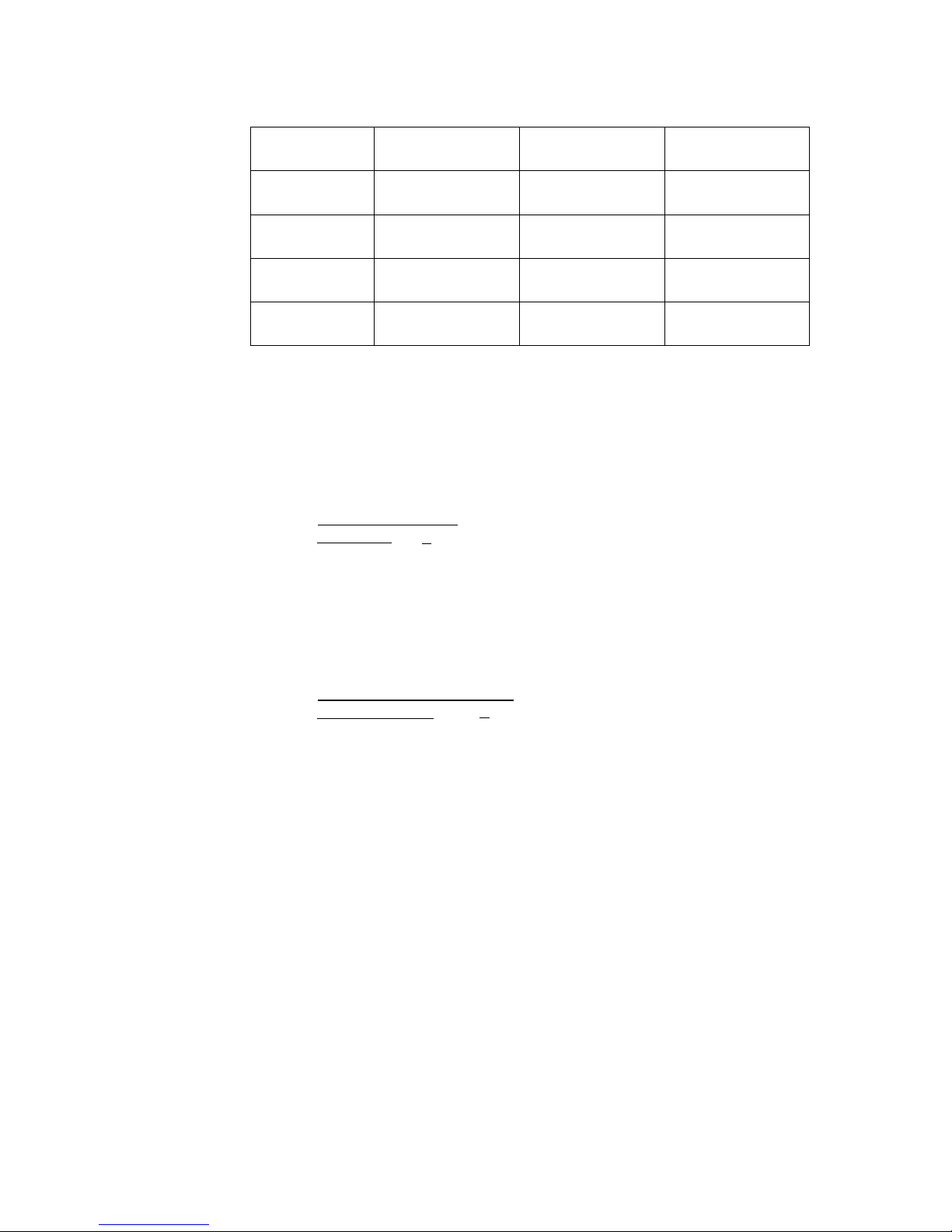
Table 1 4-1/2 digit (sampling rate:SLOW)
Range 300 mΩ 3 Ω 30 Ω 300 Ω 3kΩ 30 kΩ 300 kΩ
Resolution 10 μΩ 100 μΩ 1mΩ 10 mΩ 100 mΩ 1 Ω 10 Ω
Measurement
current
100 mA 10 mA 1mA 10 μA
Maximum
applied voltage
30 mV 300 mV 3V 300 mV 3V
Accuracy *
±0.1% rdg
.
±8 dgt.
0.08% rdg. ±3 dgt. ±0.1% rdg.±3dgt.
Temperature
coefficient
(±0.01% rdg.±0.5 dgt.)/℃
Open-terminal
voltage
7.0 Vmax
* If the sampling rate is set to MEDIUM, add 3 dgt to the digit accuracy error.
Table 2 3-1/2 digit (sampling rate:FAST)
Range 300 mΩ 3 Ω 30 Ω 300 Ω 3kΩ
Resolution 100 μΩ 1mΩ 10 mΩ 100 mΩ 1 Ω
Measurement
current
100 mA 10 mA 1mA
Maximum
applied voltage
30 mV 300 mV 3V
Accuracy ±0.2% rdg. ±5 dgt.
Temperature
coefficient
(±0.01% rdg.±0.1 dgt.)/℃
Open-terminal
voltage
7.0 Vmax
Page 17
5
────────────────────────────────────────────────────
1.2 Specifications
────────────────────────────────────────────────────
1
.2.3 Temperature Measurements
Temperature sensor Platinum resistance element
Dielectric strength 1000 VAC between the temperature sensor sheath and the
voltage terminal(-).
Accuracy assurance range 0.00℃ to 40.00℃
Resolution 0.01℃
Accuracy ±0.5℃
Temperature coefficient ±0.02×(t-23)℃
t : environment temperature where the 3227 is located (℃).
1
.2.4 Temperature Correction Function
Temperature correction range 0.00℃ to 40.00℃ (32 F to 104 F)
Standard temperature range -10.0℃ to 99.9℃ (14 F to 212 F)
Resistance temperature coefficient
range
-9999 ppm to 9999 ppm
Accuracy In the temperature correction, add the value obtained by the
expression below to the accuracy of the resistance measurement
.
±0.5α×100
(%)
1+α((t
0.5) - t
0
)
t: Environment temperature
t
0
: Standard temperature
α: Resistance temperature coefficient
0.5: Temperature measurement accuracy
Page 18
6
────────────────────────────────────────────────────
1.3 Measurements and Working Systems
────────────────────────────────────────────────────
1
.3.1 4-terminal Measurements
r
2
r
4
r
3
r
1
I
Ohmmete
r
Resistance R
0
Voltmeter
Constant current sourc
e
E
0
E
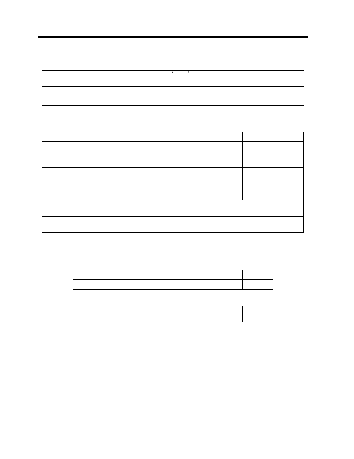
Measurement Using the 4-terminal Method
1
.3 Measurements and Working Systems
Regular 2-terminal measurement measures even the value which includes the
resistance of the measurement leads or the terminal area. Particularly, when
measuring the low resistance, it is necessary to measure the value without
this resistance value. 4-terminal measurement is able to measure that value.
4-terminal measurement and 2-terminal measurement are explained as
follows. In the figure below, there is very big input impedance in the
voltmeter, and all of the current I flows to the measured resistance R
0
. The r
1
to r
4
means the resistance of the measurement leads or the contact resistance
of the terminal area.
All of the current I flows to the measured resistance R
0
. Therefore, the
voltage drop of r
3
and r
4
become 0, and voltage E and the voltage drop E
0
of
each end of the measured resistance R
0
become equal. Accordingly, the
resistance measurement without influence of r
1
to r
4
becomes possible.
Page 19
7
────────────────────────────────────────────────────
1.3 Measurements and Working Systems
────────────────────────────────────────────────────
r
2
r
1
I
Ohmmete
r
Resistance R
0
Constant current sourc
e
E
Voltmeter
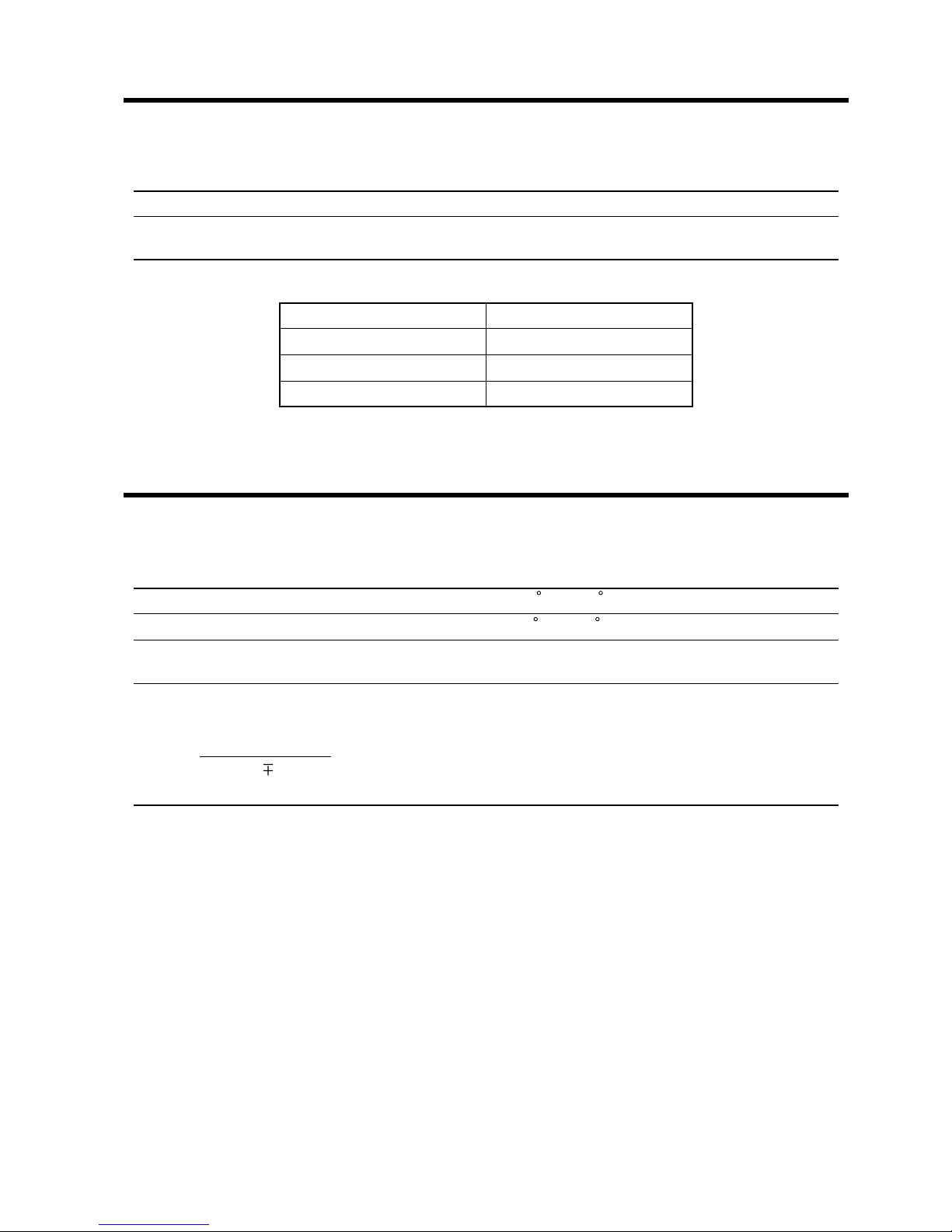
Measurement Using the 2-terminal Method
1
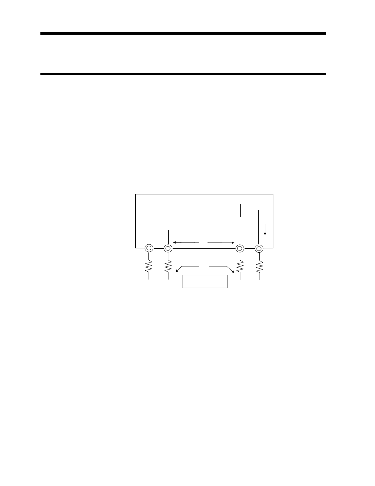
.3.2 Temperature Probe
Shield cabl
e
Platinum film resisto
r
322
7
The Internal Circuit of the Temperature Probe
The current I flows to the measured resistance R
0
and the wiring resistance r
1
and r
2
. Therefore, the measuring voltage E can be obtained by E=I(r
1
+R
0
+r
2
),
and it would include the wiring resistance r
1
and r
2
.
The 9188 TEMPERATURE PROBE makes temperature measurement and the
temperature correction function easy. In this section, explain the principle of
them.
See Section 3.4.2, "Temperature Correction and Temperature Measurement",
for connecting the temperature probe.
(1) Temperature measurement
The internal circuit of the temperature probe is as follows.
The temperature probe uses the platinum film resistor which is changeable
according to the temperature, as the temperature sensor. This probe displays
the resistance value of that register, detected by the 3227, after converting it
to the temperature using the CPU.
Page 20

8
────────────────────────────────────────────────────
1.3 Measurements and Working Systems
────────────────────────────────────────────────────
(2) Temperature Correction Function
The temperature correction function displays the optional temperature
coefficient resistance value after converting to the resistance value of the
optional temperature. The resistance depends on the ambient temperature,
and it is of little use to measure the resistance while ignoring this
temperature dependence.
In the following expression, the resistance value R
t
and R
t0
corresponds to the
resistance value of t ℃ and the measured subjects of t
0
℃ (resistance
temperature coefficient in t
0
℃ : αt
0
)
R
t
= R
t0
× {1+α
t0
× (t−t
0
)}
The 3227 obtains the correctional resistance value (R
t0
) from calculating the
temperature measured by the temperature probe (t), the resistance value of
the measured subjects (R
t
), the standard temperature (t
0
) and temperature
coefficient (α
t0
) by CPU.
For example, the resistance value of the copper wire that will be 100Ω under
30℃ would be followingly under 20℃.
R
t
R
t0
=
{1+α
t0
× (t−t
0
)}
100
=
{1+(3930×10
−6
)×(30−20)}
=96.22
See Section 5.3, "Setting the Temperature Correction" and Section 5.4,
"Executing the Temperature Correction", for how to set and execute the
temperature correction. Also see "Reference Material" at the end of this
chapter.
(3) Temperature conversion function
The temperature conversion function uses the temperature dependence of the
resistance to convert measured resistance values to temperature values and
display them.
According to JIS C4004, the temperature rise can be derived by the resistive
method as follows:
r
t
Δt=
r
0
(T + t
0
) − (T + t)
r
0
: coil resistance under cold conditions
r
t
: present coil resistance
t
0
: ambient temperature when measuring coil resistance under cold
conditions
t: present ambient temperature
T: constant (copper: 235, aluminum: 230)
Page 21

9
────────────────────────────────────────────────────
1.3 Measurements and Working Systems
────────────────────────────────────────────────────
NOTE
For example, for a copper conductor, if when the initial temperature t
0
is 20℃
the resistance value r
0
is 200 mΩ, and the present ambient temperature is 25
℃ and the measured resistance value r
t
is 210 mΩ, then the temperature rise
is given as follows:
r
t
Δt=
r
0
(T + t
0
) − (T + t)
210×10
-3
=
(200×10
-3
)×(235 + 20) - (235 + 25)
= 7.75[℃]
As a result, the present temperature of the resistance, t
r
can be found as
follows:
t
r
=t
0
+ Δt = 20 + 7.75 = 27.75℃
When the measured object is not copper or aluminum, from the expression
shown for the temperature correction and the above expression, if the
temperature coefficient is α
t0
, the constant T can be found from the following
expression:
1
T=
-t
0
α
r0
For example, since the temperature coefficient of copper at 20℃ is 3930 ppm,
the constant T at this time is given by
1
T=
- 20 = 234.5,
3930×10
-6
and is substantially the same as the constant 235 laid down by the JIS
standard.
Note that the temperature probe is only designed to measure ambient air
temperature, and it is impossible to measure the surface temperature.
If the temperature probe is to be used in the measurement, make sure that
the 3227 and the temperature probe are thoroughly warmed up before the
measurement. The temperature probe and the device to be measured should
be placed close together during the warm-up, so that both will be as close to
the same temperature as possible during the measurement.
Page 22
10
────────────────────────────────────────────────────
1.3 Measurements and Working Systems
────────────────────────────────────────────────────
1
.3.3 Measurement Value Display
S
4 Digit Display
F
3 Digit Display
M
REF
%
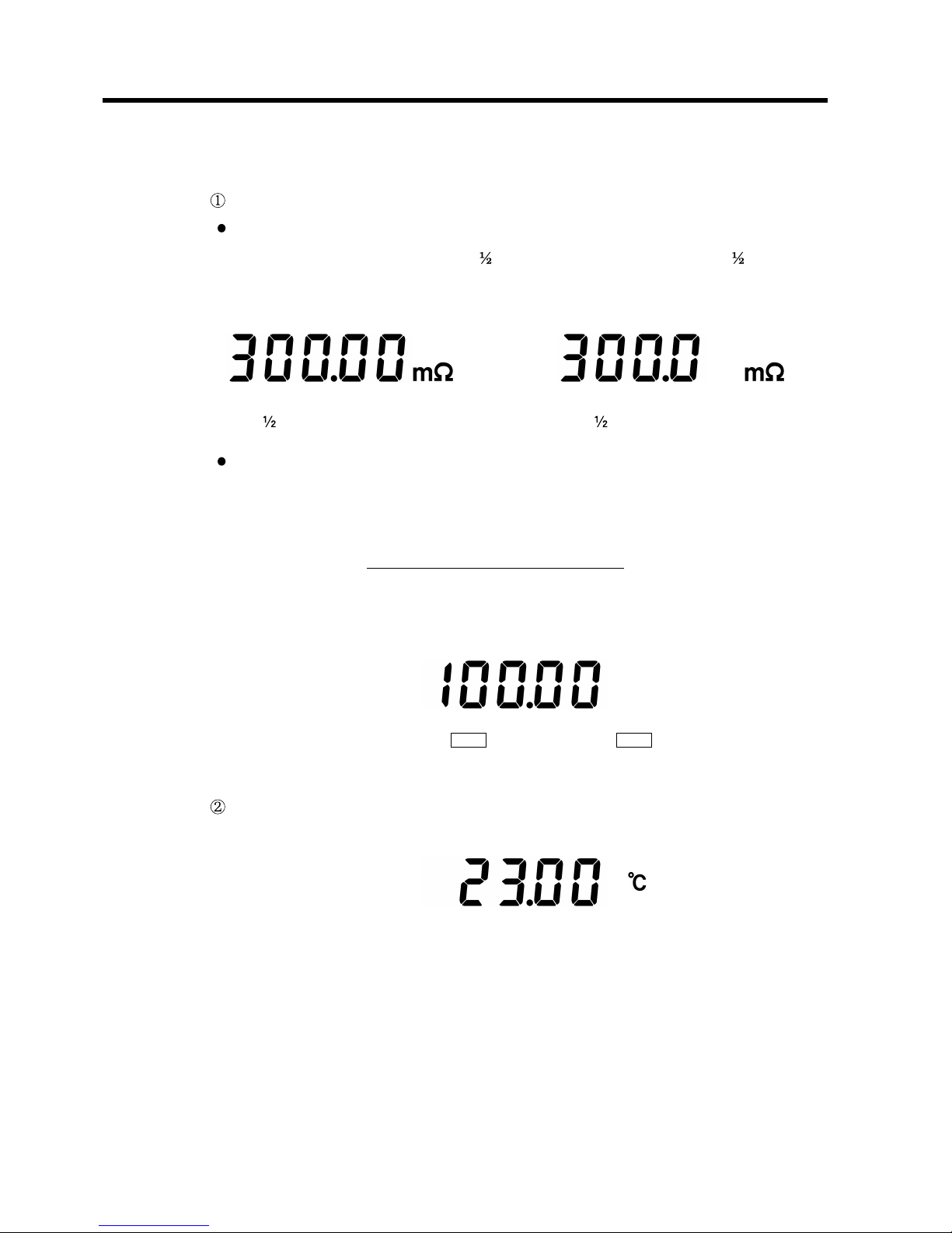
(1) Measurement value display
Resistance measurement mode
Resistance value display
Display the resistance value of 4
digit (MEDIUM, SLOW) and 3 digit
(FAST) by the sampling rate.
Deviation display
Display the deviation (see the expression below), when comparing with
comparison of the standard value/range.
Resistance measurement value
Deviation =
Standard value
See Section 1.3.4, "Comparator Function", for the comparator.
Temperature measurement mode
Page 23
11
────────────────────────────────────────────────────
1.3 Measurements and Working Systems
────────────────────────────────────────────────────
AUTO
TC
M
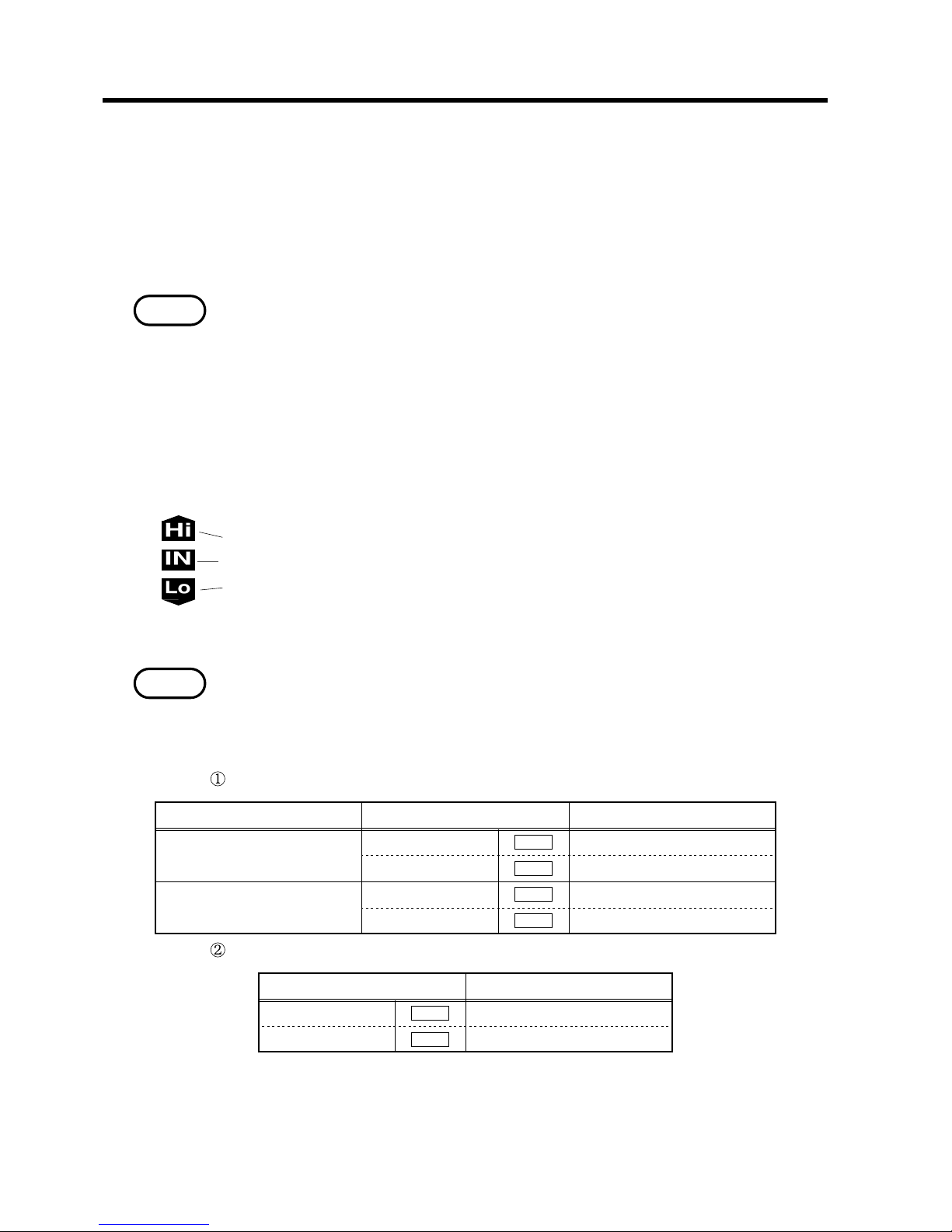
Over Flow Display
M
NG Display
S
HOLD
Invalid Data Display
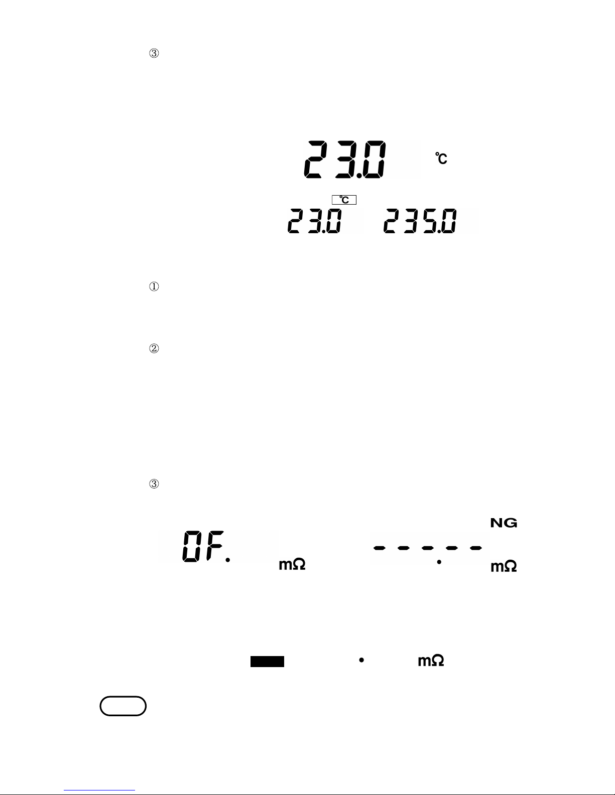
NOTE
Temperature conversion mode
When the temperature conversion function is selected at power on, when the
TC indication on the display is on continuously the converted temperature
value is displayed. When it is blinking, the temperature difference (Δt) is
displayed.
(2) The other display
When the measurement value exceeds the measuring range (30000 count), the
over flow (OF) display is indicated. However, while using the temperature
correction function, this display is indicated when the measuring range
exceeds 99999 count.
When the constant current in the source of current (SOURCE) has any error,
NG display is indicated.
・When the measured resistance value is too big, compared with the measuring
range.
Example:
・When intended to measure 300Ω in the 300mΩ range.
・When the lead wire has been ruptured.
・When the different connection has done among 4-terminals.
・When the leads has opened.
When no measurement has done after turning on the power supply, the
invalid data display is indicated.
An "NG" result is always detected even when not carrying out measurement.
Thus even in the HOLD state, if there is a constant current fault, "NG" on the
display lights with displaying the measurement value being held.
Page 24
12
────────────────────────────────────────────────────
1.3 Measurements and Working Systems
────────────────────────────────────────────────────
1
.3.4 Comparator Function
NOTE
NOTE
Setting limit Display
Resistace measurement
High limit value
HIGH
0 to 99999
Low limit value
LOW
0 to 99999
Temperature
High limit value
HIGH
-999.9 to 999.9℃
Low limit value
LOW
-999.9 to 999.9℃
Setting limit Display
Standard value
REF
0 to 99999
Range
%
0.00 to 99.99%
There are 15 comparator setting tables in the 3227, and the different contents
are able to set to each table.
See Section 5.1, "Setting the Comparator" and Section 5.2, "Executing the
Comparator", for how to set and execute the comparator. See Chapter 6,
"External Control Terminals", for the external control terminals.
The comparator is valid only in the resistance measurement mode, and unable
to use in the temperature measurement mode.
The comparator and the auto range should be used separately.
While displaying the converted temperature, the 3227 has only one
comparator setting table. The comparator tables for normal resistance
measurement cannot be used. In this case reference value/range comparisons
also cannot be executed.
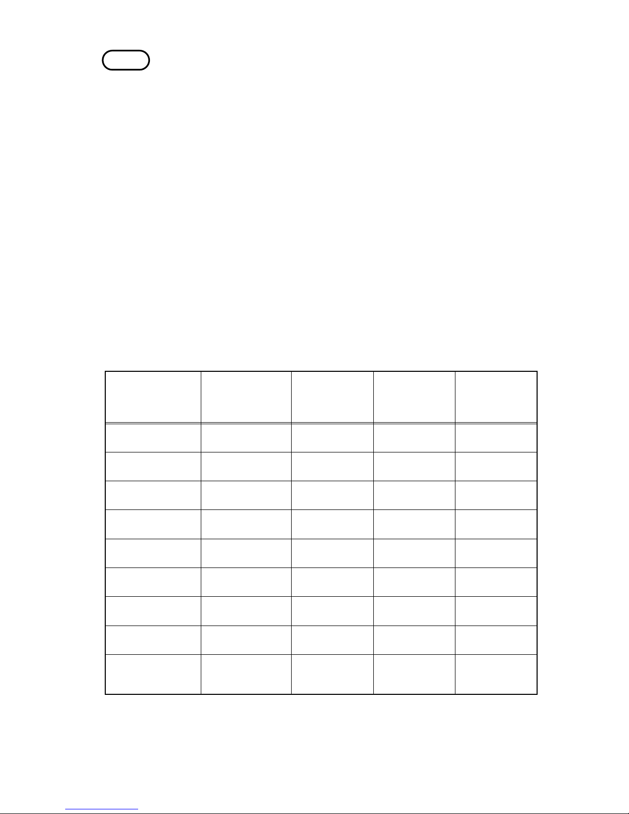
(1) Executing the comparator
The result of the comparator is displayed as follows.
Displayed value > High limit value
High limit value ≧ Displayed value ≧ Low limit value
Low limit value > Displayed value
The result of the comparator is able to output to the external control terminal.
In the over range and the NG states, the comparator result is HIGH.
(2) Comparison method of the comparator
Comparison according to high limit value/low limit value
Comparison according to standard value/range
Comparison value
High limit value = standard value + (|standard value|×range ÷ 100)
Low limit value = standard value - (|standard value|×range ÷ 100)
Page 25
13
────────────────────────────────────────────────────
1.3 Measurements and Working Systems
────────────────────────────────────────────────────
NOTE
Type Constituents [%]
Density (×10
3
)
[kg/m
3
]
Conductivity
Temperature
coefficient of
resistance (20℃
)
[ppm]
Annealed copper
wire
Cu > 99.9 8.89 1.00 to 1.02 3810 to 3970
Hard drawn coppe
r
wire
Cu > 99.9 8.89 0.96 to 0.98 3770 to 3850
Cadmium-copper
alloy wire
Cd 0.7 to 1.2 8.94 0.85 to 0.88 3340 to 3460
Silver-copper alloy
wire
Ag 0.03 to 0.1 8.89 0.96 to 0.98 3930
Chromium copper Cr 0.4 to 0.8 0.89
0.40 to 0.50
0.80 to 0.85
20
30
Corson alloy wire
Ni 2.5 to 4.0
Si 0.5 to 1.0
0.25 to 0.45 980 to 1770
Annealed aluminum
wire
AI > 99.5 2.7 0.63 to 0.64 42
Hard drawn
aluminum wire
AI > 99.5 2.7 0.60 to 0.62 40
Aldrey wire
Si 0.4 to 0.6
Mg 0.4 to 0.5
Parts containing A
l
0.50 to 0.55 36
・ When comparing by the standard value/range, the measurement value is
displayed as the deviation.
・ Always set the high limit value bigger than the low limit value.
・ Ignoring the measurement range, perform the comparison only by the
measurement count value.
・ The digit which is not indicated on the display is dealt as 0, when performing
the comparison.
(3) Buzzer mode
HL The buzzer would sound in case of HIGH or LOW.
IN The buzzer would sound in case of IN.
OFF No buzzer would sound.
(4) External control terminal mode
AUTO The comparator result is output with each samples.
EXT The comparator result is output by the MANU
―――――――
terminal state in the
external control terminal.
Reference Material
Page 26
14
────────────────────────────────────────────────────
1.3 Measurements and Working Systems
────────────────────────────────────────────────────
Diameter [mm]
Annealed copper
wire
Tin-plated annealed
copper wire
Hard drawn coppe
r
wire
0.10 to 0.26
(excluding 0.26
)
0.98 0.93
0.26 to 0.50
(excluding 0.50
)
0.993 0.94 0.96
0.50 to 2.00
(excluding 2.00
)
1.00 0.96 0.96
2.00 to 8.00
(excluding 8.00
)
1.00 0.97 0.97
α
Ct
=
1
α
20
× C
+(t 20
)
1
α
20
=
1
0.00393 × 0.9
3
+ (20 20
)
1
≒ 3650 (ppm
)
(1) Properties of metal and alloy conductive materials
(2) Conductivity of copper wire
The temperature coefficient changes in relation to temperature and
conductivity. Assume the temperature coefficient is α
20
at 20℃ and that the
temperature coefficient is α
Ct
at t (℃) with a conductivity of C. Then Ct at
around room temperature is represented as follows:
The temperature coefficient of international standard annealed copper is 3930
ppm at 20℃. For tin-plated annealed copper wire (not less than 0.10 but
below 0.26 in diameter), the temperature coefficient α
20
at 20℃ can be
calculated using the following formula:
Page 27
15
────────────────────────────────────────────────────
2.1 Front Panel
────────────────────────────────────────────────────
AUTO UP DOWN
GP-IB ADRS
ENTER
CLEAR
TC
SHIFT
COMP
LOCK
TEMP
HOLD
0 ADJ
SAMP
50/60Hz
SET
SET
INPUT
SENSE SOURCE
H
L
Rx
▼
▼
12345678910111213
14
1234567
8
91011121314
Chapter
2
Part Name
s
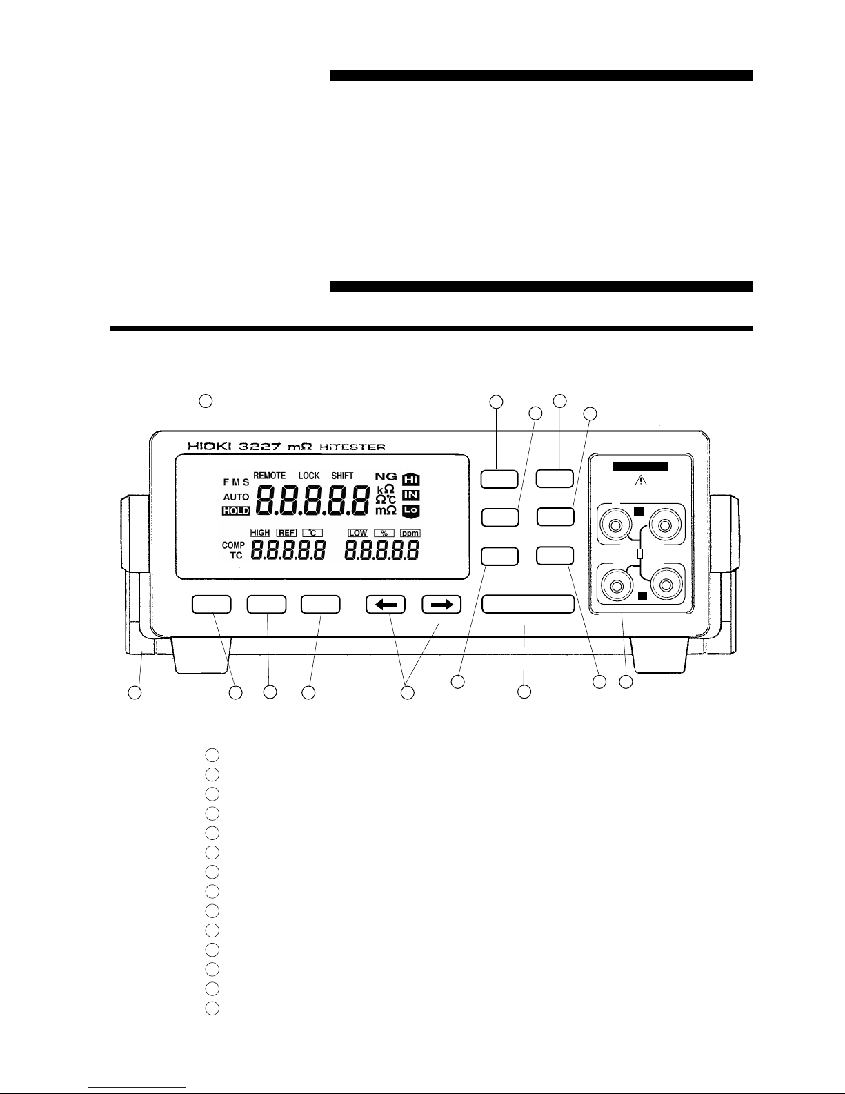
2
.1 Front Panel
Display
AUTO key
UP key
DOWN key
Cusor keys
ENTER key
TEMP key (Temperature measurement (zero adjustment) )
HOLD key (Sampling rate setting)
COMP key (Comparator setting)
LOCK key (Power supply frequency setting)
TC key (Temperature correction setting)
SHIFT key
Input terminals
Handle
Page 28
16
────────────────────────────────────────────────────
2.2 Rear Panel
────────────────────────────────────────────────────
1516171819
20
1
51617181920
2
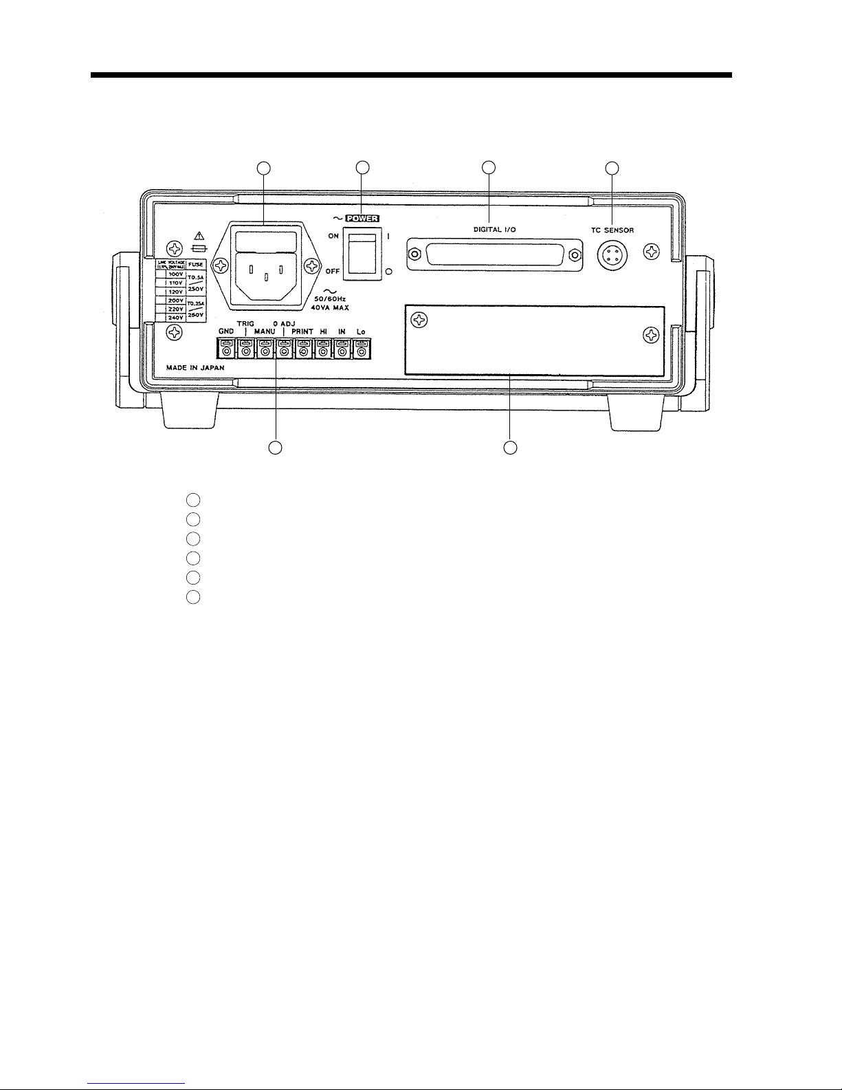
.2 Rear Panel
Power supply inlet
POWER switch
Digital I/O connector
Temperature probe connector
External control terminal block
Option slot
Page 29
17
────────────────────────────────────────────────────
2.3 Displays
────────────────────────────────────────────────────
REMOTE LOCK SHIFT
FMS
AUTO
HOLD
k
HIGH
REF
LOW
%
ppm
COMP
TC
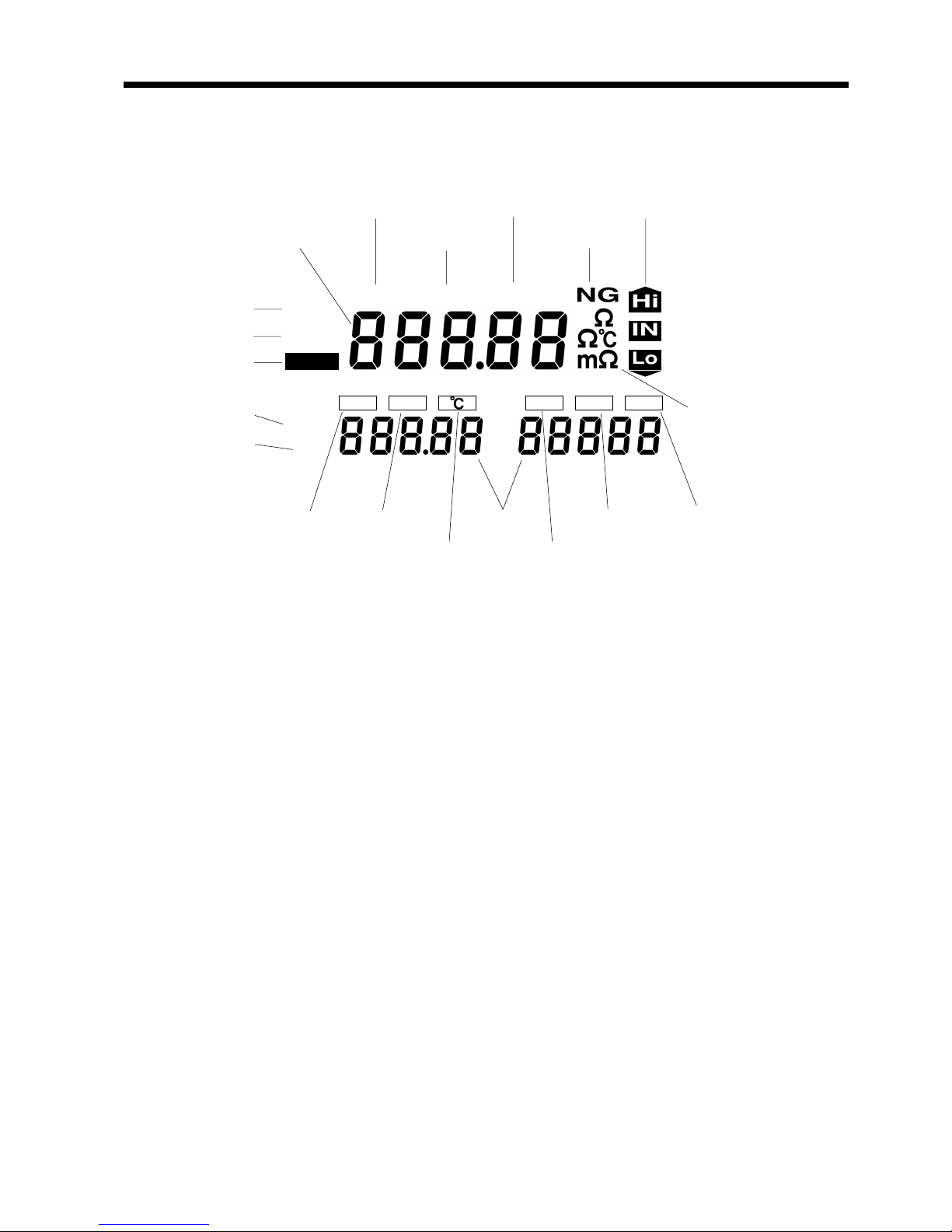
High limit value Standard value Setting value Range Resistance coefficien
t
Standard temperature Low limit value
Sampling rat
e
Auto rang
e
Hold stat
e
Comparato
r
Temperatur
e
correctio
n
Measurement unit
Remote state Key shift state Comparator resu
lt
Measurement value Key lock state NG
2
.3 Displays
Page 30
18
────────────────────────────────────────────────────
2.4 Accessory and Options
────────────────────────────────────────────────────
Sensor par
t
Cabl
e
Connecto
r
HIOKI 9188
MADE IN JAPAN
GP-IB connecto
r
9588 GP-IB INTERFACE
GP-IB
MADE IN JAPAN
9589 PRINTER INTERFACE
MADE IN JAPAN
Printer connecto
r
2
.4 Accessory and Options
Accessory
9188 TEMPERATURE PROBE
Options
9588 GP-IB INTERFACE
9589 PRINTER INTERFACE
Page 31

19
────────────────────────────────────────────────────
3.1 Installing the Interfaces
────────────────────────────────────────────────────
WARNIN
G
To prevent electric shock, before adding or replacing the interface,
check that the power for the unit is off and the power cord and
connectors are disconnected. The fixing screws must be firmly
tightened, or the input unit may not function up to specification, or may
even fail.
To avoid the danger of electric shock, never operate the unit with an
interface removed. If you should wish to use the unit after removing an
interface, fit a blank panel over the opening of the removed unit.
NOTE
Chapter
3
Unit Installatio
n
3
.1 Installing the Interfaces
The following is the explanation for the installing method of the 9588 GP-IB
INTERFACE and the 9589 PRINTER INTERFACE.
Do not install any interface unit except the 9588 and the 9589.
Page 32

20
────────────────────────────────────────────────────
3.1 Installing the Interfaces
────────────────────────────────────────────────────
On the rear panel of this unit, the option slot to install the interfaces is
covered with the blank plate. Please install the interfaces according to
following order.
1. Take off the blank plate. (Please keep the screws.)
2. Insert the interface with holding the guide rail between the rail of the 3227.
3. Insert the interface tightly, be sure to tighten the screws which have been
unscrewed in step 1.
Page 33

21
────────────────────────────────────────────────────
3.2 Turning on the Power Supply
────────────────────────────────────────────────────
3
.2 Turning on the Power Supply
(1) Confirm whether the power supply voltage shown on the rear panel and that
intended to use are same.
(2) Confirm whether the POWER switch is OFF.
(3) Connect the accessory power code to the power supply inlet.
(4) Connect the power code to the 3-pole power outlet which has the protective
grounding terminal. When using the 2-pole power outlet, use the accessory
converter plug. In this case, always ground the green grounding wire of that
plug.
(5) Turn on the
POWER switch.
Press the
TC key (temperature conversion key) until it beeps to select the
temperature correction function or the temperature conversion function.
If the last setting was the temperature correction function, this switches to the
temperature conversion function and vice versa.
(6) Start the self test (self testing of the unit).
Light all displays.
Check ROM, RAM, the back up and the proofreading data, and the error
indications are displayed for the items of which any errors have generated.
When no error has generated, these indications are not displayed.
See Section 7.2, "Error Indications", for the error indications.
Page 34

22
────────────────────────────────────────────────────
3.2 Turning on the Power Supply
────────────────────────────────────────────────────
When the temperature correction
function is selected
TC
When the temperature conversion
function is selected
NOTE
Display the name of this unit, the version number and the power supply
frequency settings.
TC on the display indicates the function to be used, the temperature correction
function or temperature conversion function. When TC on the display is
blinking, the temperature conversion function is used.
(7) Enter the normal measurement state.
・ Before measurement, perform the warm up at least for 30 minutes after
turning on the power supply.
・ This unit contains the back up function. The previous settings appear, when
turning on the power supply. The back up function works until the internal
lithium battery has consumed.
・ The battery would run down after four years. Please contact your nearest
service representative for the battery change.
・ It is not possible to use the temperature correction function and the
temperature conversion function at the same time.
・ In resistance measurement mode, if pressing the
TC key switches to the ℃
indication on the display, the temperature conversion function can be used.
Page 35

23
────────────────────────────────────────────────────
3.3 Selecting the Power Supply Frequency
────────────────────────────────────────────────────
SHIFT
LOCK
50/60Hz
DOWNUP
ENTER
CLEAR
NOTE
3
.3 Selecting the Power Supply Frequency
1. Press the SHIFT key and enter the shift states.
"SHIFT" on the display lights.
2. Press the LOCK key (power supply frequency setting
key) and enter the power supply frequency setting
mode.
The power supply frequency is displayed with flashing.
3. Press the
UP or DOWN key to change the power supply
frequency.
50 Hz: Set the power supply frequency to 50.
60 Hz: Set the power supply frequency to 60.
4. Press the
ENTER key and decides the power supply
frequency. Then, return to the measurement mode.
When the incorrect power supply frequency has set, it is impossible to
measure accurately. Always set the power supply frequency.
Page 36

24
────────────────────────────────────────────────────
3.4 Preparation for Measurements
────────────────────────────────────────────────────
3
.4.1 Resistance Measurements
Re
d
Blac
k
Re
d
Blac
k
SOURCE
SOURCE
SENSE
SENCE
SOURCE SENSE
SOURCE SENSE
Re
d
Blac
k
SOURCE
SENSE
SOURCE
SENSE
Red
Black
SOURCE
SENSE
SOURCE
SENSE
Shield
NOTE
3
.4 Preparation for Measurements
(1) When using the 9287 CLIP-TYPE LEAD (accessory)
Insert the lead to the input terminal of the front panel. Connect them with
putting the red ▼ mark of the 3227 upon the same mark of the red lead, and
the black ▼ mark upon the same mark of the black lead.
(2) When using the self-made leads
Connect them as follows.
When making the leads on your own work, be sure to shield to measure
accurately, and make the cable length within 5 m (the resistance of the wires
are 100 mΩ/m or less.)
Page 37

25
────────────────────────────────────────────────────
3.4 Preparation for Measurements
────────────────────────────────────────────────────
3
.4.2 Temperature Correction and Temperature Measurements
NOTE
Connect the 9188 to the temperature probe connector of the rear panel with
putting the grooves of the temperature probe and that connector together,
until it clicks.
Note that the temperature probe is only designed to measure ambient air
temperature, and it is impossible to measure the surface temperature.
If the temperature probe is to be used in the measurement, make sure that
the 3227 and the temperature probe are thoroughly warmed up before the
measurement. The temperature probe and the device to be measured should
be placed close together during the warm-up, so that both will be as close to
the same temperature as possible during the measurement.
Page 38

26
────────────────────────────────────────────────────
3.5 Handle Operation
────────────────────────────────────────────────────
3
.5 Handle Operation
The handle is able to use as the stand. Pull the each side of the handle and
turn it, then push it in.
The handle is able to fix every 22.5。. Use after fixing it to the proper direction.
Page 39

27
────────────────────────────────────────────────────
4.1 Operating Procedure
────────────────────────────────────────────────────
4
.1.1 Function Classes
Turning on the powe
r
Self test
Resistance measurement mode
Comparator setting mode
Temperature correction setting mode
Frequency setting mode
GP-IB address setting mode
Temperature measurement mode
Selecting the measurement range
Selecting the sampling rate
Selecting the comparator executing
Selecting the temperature correction
executing
Selecting the measurement holding
Executing the zero adjustment
Selecting the measurement holding
A
B
A: This shows every kind of mode. The key input are accepted in this mode. Otherwise, in the
resistance measurement mode and the temperature measurement mode, execute and display
the measurement.
B: Select and execute each settings. After selecting or executing, return to the primary mode.
Selecting the temperature correction/the temperature conversio
n
Temperature conversion setting mode
Selecting the temperature
conversion executing
Chapter
4
Basic Operation
s
4
.1 Operating Procedure
Page 40

28
────────────────────────────────────────────────────
4.1 Operating Procedure
────────────────────────────────────────────────────
NOTE
4
.1.2 Key Shift States
TEMP
0 ADJ
4
.1.3 Key Lock State
LOCK
50/60Hz
4
.1.4 Remote State
NOTE
・ It is impossible to move to the GP-IB address setting mode without installing
the GP-IB interface unit as an option.
・ It is not possible to use the temperature correction function and the
temperature conversion function at the same time.
Under the key shift states, "SHIFT" on the display lights. When pressing any
key under this state, execute the function shown in the blue words under the
keys.
When pressing any key out of this state, execute the function shown in the
white words on the keys.
TEMP Executable functions out of the key shift state (white words).
0 ADJ Executable functions under the key shift state (blue words).
For example, pressing
TEMP key executes zero adjustment under the key shift
state, and selects the measurement mode out of the key shift state.
Pressing the
SHIFT key is able to select either the key shift state or the normal
state.
Under the key lock states, "LOCK" on the display lights and all key except are
invalid. To enter or release the key lock state, press the
LOCK key.
Under the remote states, "REMOTE" on the display lights and all key except
LOCK are invalid. When receiving any commands from GP-IB, enter this state.
In the each kind of setting mode, such as the comparator setting mode, when
receiving any commands from GP-IB, the 3227 returns to the primary
measurement mode automatically and enters the remote state.
To release the remote state, press
LOCK key, except receiving LLO (Local Lock
Out) command from GP-IB. When receiving this command, to release the
remote state, send GTL (Go To Local) command from GP-IB.
Page 41

29
────────────────────────────────────────────────────
4.1 Operating Procedure
────────────────────────────────────────────────────
4
.1.5 Valid Input Key Table
● : Key input is valid.
−: Key input is invalid.
Keys
Out of the shift state In the shift state
Lock
state
Remote
state
Resistanc
e
Temper-
ature
Setting Res istanc
e
Temper-
ature
Setting
TEMP
0 ADJ
● ● − ● − − − −
COMP
SET
● − − ● *
4
● − − −
TC
SET
● − − ● *
4
● − − −
HOLD
SAMPL
● ● − ● − − − −
LOCK
50/60Hz
● ● ● ● ● − ● ●*3
SHIFT
● ● ● *
2
● ● ● *
2
− −
AUTO
● *
5
− ● *
6
− − − − −
UP
● − ● − − − − −
DOWN
● − ● − − − − −
● − ● *1 − − − − −
GP-IB ADRS
● − ● *1 ● ● − − −
ENTER
CLEAR
− − ● − − ● *
2
− −
*1: Invalid when setting the GP-IB address or the power supply frequency
*2: Valid only when setting the comparator tables or the temperature conversion tables
*3: Invalid under the LLO (Local Lock State) state
*4: Invalid under the holding state and when using the auto range (excluding when the temperature
conversion functino is selected)
*5: Invalid when using the comparator or displaying the temperature conversion
*6: Valid only when setting the temperature conversion tables
Page 42

30
────────────────────────────────────────────────────
4.2 Selecting the Measurement Mode
────────────────────────────────────────────────────
TEMP
0 ADJ
M
Resistance Measurement Mode
Temperature Measurement Mode
NOTE
4
.2 Selecting the Measurement Mode
Pressing the TEMP key (temperature measurement key) selects either the
resistance measurement mode or the temperature measurement mode.
When the 9188 is not connected, the temperature mode is unable to select. If
intend to select, error is generated.
Page 43

31
────────────────────────────────────────────────────
4.3 Resistance Measurement Mode
────────────────────────────────────────────────────
4
.3.1 Selecting the Sampling Rate
SHIFT
HOLD
SAMPL
S
SLOW
M
MEDIUM
F
FAST
S
N
G
k
REF
%
SLOW
REF
%
M
N
G
k
MEDIUM
F
N
G
k
REF
%
FAST
4
.3 Resistance Measurement Mode
1. Press the SHIFT key and enter the shift states. "SHIFT" on the display
lights.
2. Press the
SAMPL key (sampling rate setting key) and select the sampling
rate.
3. The sampling rate changes in order of SLOW, MEDIUM and FAST with
repeating the step 1. and 2., and the displays change as follows.
Resistance value display
Deviation display
Page 44

32
────────────────────────────────────────────────────
4.3 Resistance Measurement Mode
────────────────────────────────────────────────────
S
AUTO
TC
SLOW
M
AUTO
TC
MEDIUM
F
AUTO
TC
FAST
NOTE
4
.3.2 Selecting the Measuring Range
AUTO
UP
DOWN
Temperature conversion display
When the sampling rate is FAST, 30 k and 300 kΩ range are unable to select.
When set the sampling rate to FAST in 30 kΩ and 300 kΩ range, the
measurement range becomes 3 kΩ range automatically.
The measurement range can also be selected by the external control terminal.
See Chapter 6, "External Control Terminals", for the external control
terminals.
Auto range
Pressing the
AUTO key selects whether the auto range or the manual range.
In case of the auto range, on the display lights, the measuring range changes
to proper range according to the resistance value of the measured subjects.
Manual range
Select the measuring range by the
UP and DOWN key.
When pressing these keys under the auto range state, the range would be the
manual range, but not select any measuring range.
Page 45

33
────────────────────────────────────────────────────
4.3 Resistance Measurement Mode
────────────────────────────────────────────────────
M
M
300 mΩrange 3Ωrange
M
M
30Ωrange 300Ωrange
M
M
k
k
3kΩrange 30 kΩrange
M
k
300 kΩrange
NOTE
The displays change as follows, according to the measuring range (in case of
the resistance value display)
When intend to execute the comparator during using the auto range, the
range becomes the manual range automatically.
During executing the comparator, the auto range is unable to use.
When the sampling rate is FAST, 30k Ω and 300 kΩ range are unable to
select.
During displaying the deviation, the state of the measuring range are not
displayed on the display. To confirm it, turn off the comparator once.
When moving the measuring range under the measurement holding state, the
measuring range is able to change, but the measurement point value is unable
to change.
During temperature conversion display, auto ranging is used. It is not
possible to select the measurement range.
Page 46

34
────────────────────────────────────────────────────
4.3 Resistance Measurement Mode
────────────────────────────────────────────────────
4
.3.3 Zero Adjustment
Red Black
SENSE
Right method Wrong method
SOURCE
SENSE
SENSE
SOURSE
Red Black
SOURCE
SENSE
SOURCE
SENSE
Connect
SENSE SOURCE
HI LO HI LO
Connect
SHIFT
TEMP
0 ADJ
NOTE
The zero adjustment cancels the wiring resistance in case that the accurate 4terminal measurement is impossible. This is also able to execute from the
external control terminal.
See Chapter 6, "External Control Terminal", for details.
(1) Short the leads as follows.
When executing by the 9287
When executing by the self-made lead
(2) Press the
SHIFT key and enter the shift states. "SHIFT" on the display lights.
(3) Press the
0 ADJ key and execute the zero adjustment.
Display "O AdJ" during executing the zero adjustment.
After the zero adjustment, return to the resistance measurement mode.
To measure accurately, the leads should connect correctly.
The zero adjustment is valid only in the measuring range which execute it.
Always execute the zero adjustment in the measuring range which is intended
to use.
The zero adjustment is unable to execute while using the auto range.
However, during using the auto range, the wiring resistance is canceled
according to the result of the zero adjustment executed in the manual range.
The zero adjustment is unable to execute under the holding state.
The range able to execute the zero adjustment is within 100 count. When the
value over 100 count is input, an error is generated.
Page 47

35
────────────────────────────────────────────────────
4.4 Resistance Measurement
────────────────────────────────────────────────────
NOTE
R
x
4
.4 Resistance Measurement
(1) Insert the measurement lead into the input terminal.
See Section 3.4.1, "Resistance Measurement", for how to connect the
measurement leads.
To measure accurately, the leads should connect correctly.
(2) Set the measurement mode to the resistance measurement.
See Section 4.2, "Selecting the Measurement Mode", for how to select the
measurement mode.
(3) Select the sampling rate and the measurement range.
(4) Execute the zero adjustment.
See Section 4.3, "Resistance Measurement Mode", for the sampling rate,
selecting the measuring range, and the zero adjustment.
(5) Connect the lead to the measured subjects (Rx), and read the measurement
value.
See Section 1.3.3, "Measurement Value Display", for measurement value
display.
Page 48

36
────────────────────────────────────────────────────
4.5 Temperature Measurement
────────────────────────────────────────────────────
NOTE
4
.5 Temperature Measurement
(1) Connect the 9188 to the temperature probe connector.
See Section 3.4.2, "Temperature Correction and Temperature Measurements",
for connecting the temperature probe.
(2) Set the measurement mode to the temperature measurement.
See Section 4.2, "Selecting the Measurement Mode", for selecting the
measurement mode.
(3) Put the sensor part of the 9188 to the measuring place, and read the
measurement value.
See Section 1.3.3 "Measurement Value Display", for the display of the
measurement value.
・ The temperature measurement is unable to execute when the temperature
probe is unconnected or ruptured.
・ To prevent the inaccurate temperature measurement, do not take the
temperature probe with bare hands.
・ It is impossible to measure with the sensor part of the temperature probe on
the subjects. It should be used only for measuring the surrounding
temperature.
・ If the temperature probe is to be used in the measurement, make sure that
the 3227 and the temperature probe are thoroughly warmed up before the
measurement. If it is not used to the surrounding temperature, the serious
error is generated.
Page 49

37
────────────────────────────────────────────────────
4.6 Holding the Measurement Value
────────────────────────────────────────────────────
HOLD
SAMPL
NOTE
4
.6 Holding the Measurement Value
During holding the measurement, the value which is obtained on the HOLD
key is pressed is held. The measurement and its display are not renewed
except when the external control terminal requires the measurement.
During free-running, they are renewed according to the rate which is set as
the sampling rate. See Chapter 6, "External Control Terminal", for the
measurement requirement from the external control terminal.
Pressing the
HOLD key selects either the measurement holding or the free-
running.
During holding the measurement, "HOLD" on the display lights.
An "NG" result is always detected even when not carrying out measurements.
Thus even in the HOLD state, if there is a constant current fault, "NG" on the
display lights.
Page 50

38
────────────────────────────────────────────────────
4.6 Holding the Measurement Value
────────────────────────────────────────────────────
Page 51

39
────────────────────────────────────────────────────
5.1 Setting the Comparator
────────────────────────────────────────────────────
5
.1.1 Setting the Comparator 1
SHIFT
COMP
SET
N
G
k
HIGH
LOW
Comparator table number Buzzer mode External control terminal mod
e
Comparison method
High limit value or standard valu
e
Low limit value or rang
e
NOTE
HIGH
LOW
Chapter
5
Applied Operation
s
5
.1 Setting the Comparator
(1) Press the SHIFT key and enter the shift states. "SHIFT" on the display lights.
(2) Press the
COMP key and enter the comparator table setting mode.
The comparator table which never has been set or been invalidated in Section
5.1.3, "Eliminating the Comparator Table" is displayed as shown below.
Page 52

40
────────────────────────────────────────────────────
5.1 Setting the Comparator
────────────────────────────────────────────────────
HIGH
LOW
GP-IB ADRS
DOWN
UP
NOTE
ENTER
CLEAR
NOTE
While displaying the converted temperature, the 3227 has only one
comparator setting table. In this case reference value/range comparisons also
cannot be executed. The comparator setting in this case is displayed as shown
below.
(3)Move the flashing cursor to the setting items with the cursor keys.
(4) Set the items with the
UP or DOWN key.
See Section 1.3.4, "Comparator Function", for the details of the setting
contents.
Select the comparator table number ( "01"to "15").
During using the temperature conversion function, comparator table number
is unable to change.
Select the buzzer mode.
HL The buzzer sounds in case of HIGH or LOW.
IN The buzzer sounds in case of IN.
OF No buzzer sound.
Select the mode of the external control terminal
A The comparator result is output with each samples.
E The comparator result is output by the "MANU
―――――――
" state in the external
control terminal.
Select the comparison method of the comparator
HIGH , LOW The comparator is compared as high limit value/low limit value.
REF, % The comparator is compared as standard value/range.
Select either high limit value/low limit value or standard value/range.
To change the value, move the cursor to that digit ("0" to "9").
The comparison range of the comparator is decided by these selection and the
comparison method of the comparator.
(5) Pressing the
ENTER key decides the setting contents and return to the
resistance measurement mode. Start comparing of the comparator according to
the comparator table.
Always set the high limit value bigger than the low limit value. If the bigger
low limit value is set, the setting contents are not decided, and the mode does
not return to the resistance measurement mode.
Page 53

41
────────────────────────────────────────────────────
5.1 Setting the Comparator
────────────────────────────────────────────────────
5
.1.2 Setting the Comparator 2
GP-IB ADRS
N
G
k
HIGH
LOW
Comparison
method
High limit value or standard value Low limit value or rang
e
NOTE
GP-IB ADRS
DOWN
UP
ENTER
CLEAR
NOTE
(1)Pressing the cursor keys, enter the comparator setting mode.
In this mode, set the current comparator table to be used. When the
comparator is not used, set the comparator table 1.
(2) Move flashing cursor to the setting items with the cursor keys.
(3) Set the items with the
UP or DOWN key.
See Section 1.3.4, "Comparator Function", for the details of the setting
contents.
Select the comparison method of the comparator
HIGH , LOW The comparator is compared as high limit value/low limit value.
REF, % The comparator is compared as standard value/range.
Select either high limit value/low limit value or standard value/range.
To change the value, move the cursor to that digit ("0" to "9").
The comparison range of the comparator is decided by these selection and the
comparison method of the comparator.
(4) Pressing the
ENTER key decides the setting contents and return to the
resistance measurement mode. Start comparing of the comparator according to
the comparator table.
Always set the high limit value bigger than the low limit value. If the bigger
low limit value is set, the setting contents are not decided, and the mode does
not return to the resistance measurement mode.
Page 54

42
────────────────────────────────────────────────────
5.1 Setting the Comparator
────────────────────────────────────────────────────
5
.1.3 Eliminating the Comparator Table
SHIFT
DOWNUP
ENTER
CLEAR
COMP
SET
SHIFT
(1) Press the SHIFT key and enter the shift states.
"SHIFT" on the display lights.
(2) Press the
COMP key and enter the comparator table
setting mode.
(3) Select the comparator table intend to eliminate.
See Section 5.1.1, "Setting the Comparator Table", for
details.
(4) Press the
SHIFT key and enter the shift states.
"SHIFT" on the display lights.
(5) Pressing the
CLEAR (ENTER) key invalidates the
displaying comparator table and return to the
resistance measurement.
In this case, the comparator is not executed. (It would
be OFF.)
Page 55

43
────────────────────────────────────────────────────
5.2 Executing the Comparator
────────────────────────────────────────────────────
COMP
SET
NOTE
5
.2 Executing the Comparator
Pressing the COMP key displays the comparator table number in order ("01" to
"15", "OFF"). In this case, skip the comparator table which has not been set
or been invalidated in Section 5.1.3, "Eliminating the Comparator Table."
Return to the resistance measurement mode after displaying the comparator
table number about for a second, and execute the comparator.
When intend to execute the comparator during using the auto range, the
range becomes the manual range automatically. During executing the
comparator, the auto range is unable to use.
Page 56

44
────────────────────────────────────────────────────
5.3 Setting the Temperature Correction
────────────────────────────────────────────────────
SHIFT
TC
SET
GP-IB ADRS
DOWN
UP
ENTER
CLEAR
ppm
Standard temperature Temperature coefficient
NOTE
5
.3 Setting the Temperature Correction
(1) Press the SHIFT key and enter the shift states. "SHIFT" on the display
lights.
(2) Press the
TC key and enter the temperature correction setting mode.
(3) Move flashing display to the setting items with the cursor keys.
(4) Set the digits of the standard temperature or the temperature coefficient
with the UP or DOWN key ("0" to "9","-").
(5) Pressing the enter key decides the setting contents and return to the
resistance measurement mode. Start executing the temperature correction
according to the setting contents.
・ When intend to decide the setting contents with the
ENTER key in case that
standard temperature exceeds the range of -10.0℃ to 99.9℃,the error is
generated. In this case, the setting contents are not decided, and the mode
does not return to the resistance measurement mode.
・ When the temperature conversion function is selected at power on, the setting
screen for the temperature conversion function appears.
・ See Section 5.5, "Setting the Temperature Conversion", for details.
Page 57

45
────────────────────────────────────────────────────
5.4 Executing the Temperature Correction
────────────────────────────────────────────────────
TC
SET
NOTE
5
.4 Executing the Temperature Correction
Pressing the TC key selects whether executing the temperature correction or
not.
When executing the temperature correction, "TC" on the display lights.
When the 9188 is not connected, the temperature mode is unable to select. If
intend to select, an error is generated.
When the value after executing the temperature correction exceeds 99999
count, the over flow display is indicated. For example, in case that the
standard temperature is set to 90.0℃,the temperature coefficient is set to
8000 ppm, the measurement value is 30000 count, and the environment
temperature is 0 ℃,the corrected resistance value exceeds 99999 count (see
the expression below), and the over flow display is indicated.
30000
Rt =
= 107142 (count)
1 + 8000 × 10
-6
×(0-90.0)
When the temperature conversion function is selected at power on, the
temperature conversion function is executed.
For details, see Section 5.6, "Excecuting the Temperature Conversion
Function".
Page 58

46
────────────────────────────────────────────────────
5.5 Setting the Temperature Conversion
────────────────────────────────────────────────────
TC
SET
SHIFT
Table Number Display
Initial resistance value
Initial temperature Constant
Setting Screen
AUTO
NOTE
GP-IB ADRS
DOWN
UP
ENTER
CLEAR
NOTE
5
.5 Setting the Temperature Conversion
(1) Press the SHIFT key and enter the shift states. "SHIFT" on the display lights.
(2) Pressing the
TC key first displays the temperature conversion table number
for a while, then enters the temperature conversion setting mode. Pressing
the
TC key again makes it possible to select the table number.
(3) Pressing the
AUTO key sets the initial resistance and initial temperature
values to the measured values before entering the temperature conversion
mode. The constant value is also set to 235.0 (constant for copper).
When setting the current measurement value by pressing the
AUTO key, if a
valid resistance value or temperature is not measured, the initial resistance
value is set to a 99999 display value (current measurement range) and the
initial temperature is set to 99.9 ℃.
(4) Move flashing display to the setting items with the cursor keys.
(5) Set the digits of the initial resistance, the initial temperature, or the constant
with the
UP or DOWN key.
(6) Pressing the ENTER key decides the setting contents and return to the
temperature conversion mode. Start executing the temperature conversion
according to the setting contents.
・ The setting range for each item is as follows. An attempt to set a value out of
range generates an error. In this case, the setting contents are not decided,
and the mode does not return to the measurement mode.
Initial resistance: 0.00 mΩ to 999.99 kΩ
Initial temperature: -10.0℃ to 99.9℃
Constant: -999.9 to 999.9
・ When the temperature correction function is selected at power on, the setting
screen for the temperature correction function appears. See Section 5.3,
"Setting the Temperature Correction."
Page 59

47
────────────────────────────────────────────────────
5.6 Executing the Temperature Conversion
────────────────────────────────────────────────────
TC
SET
S
AUTO
Resistance Value Display
S
AUTO
TC
Temperature Conversion Display
S
AUTO
TC
Δt Display
DOWN
UP
NOTE
5
.6 Executing the Temperature Conversion
(1) Pressing the TC key changes the displays as shown below, cycling the
measurement mode through the resistance value display, the temperature
conversion display, and the Δt display.
(2) Pressing the
UP or DOWN key selects the temperature conversion table. After
displaying the temperature conversion table number for a while, start
executing the temperature conversion according to the selected table.
・ Connect the 9188 TEMPERATURE PROBE to execute the temperature
conversion. If it is not connected, an execution error is generated.
・ When temperature correction function is selected at power on, the function is
executed.
Page 60

48
────────────────────────────────────────────────────
5.6 Executing the Temperature Conversion
────────────────────────────────────────────────────
Page 61

49
────────────────────────────────────────────────────
6.1 Connector
────────────────────────────────────────────────────
6
.1.1 Terminal Block
TRIG 0 ADJ
GND MANU PRINT Hi IN Lo
Signals Input and output Signals Input and output
GND Ground
PRINT
――――――
Input
TRIG
―――――
Input Hi Output
MANU
―――――
Input IN Output
0 ADJ
―――――
Input Lo Output
Chapter
6
External Control Termina
ls
6
.1 Connector
Page 62

50
────────────────────────────────────────────────────
6.1 Connector
────────────────────────────────────────────────────
6
.1.2 Digital I/O
11920
37
Socket side
Pin
numbe
r
Input and
output
Signals
Pin
numbe
r
Input and
output
Signals
1 Power supply VCC 20 Power supply VCC
2 Power supply VCC 21 Power supply VCC
3 Output BCD (1 digit) bit 0 22 Output BCD (1 digit) bit 1
4 Output BCD (1 digit) bit 2 23 Output BCD (1 digit) bit 3
5 Output BCD (2 digit) bit 0 24 Output BCD (2 digit) bit 1
6 Output BCD (2 digit) bit 2 25 Output BCD (2 digit) bit 3
7 Output BCD (3 digit) bit 0 26 Output BCD (3 digit) bit 1
8 Output BCD (3 digit) bit 2 27 Output BCD (3 digit) bit 3
9 Output BCD (4 digit) bit 0 28 Output BCD (4 digit) bit 1
10 Output BCD (4 digit) bit 2 29 Output BCD (4 digit) bit 3
11 Output BCD (5 digit) bit 0 30 Output BCD (5 digit) bit 1
12 Output BCD (5 digit) bit 2 31 Output BCD (5 digit) bit 3
13 Output EOC 32 Output NG
14 Input
COMP 0
――――――――
33 Input
RANGE 0
―――――――――
15 Input
COMP1
――――――――
34 Input
RANGE 1
―――――――――
16 Input
COMP 2
――――――――
35 Input
RANGE 2
―――――――――
17 Input
COMP 3
――――――――
36 Ground GND
18 Ground GND 37 Ground GND
19 Ground GND
Using socket DCSP-JB37S (made by Japan aviation electron)
50 pins receptacle
Adaptive pin DCSP-JB37P (conform to made by Japan aviation electron)
50 pins plug
Page 63

51
────────────────────────────────────────────────────
6.2 Connecting Method
────────────────────────────────────────────────────
6
.2.1 Terminal Block
6
.2.2 Digital I/O
CAUTIO
N
・To avoid damage to the unit, do not input a voltage or current exceeding the
rated input to the output terminal.
・To avoid damage to the unit, do not input a voltage or current exceeding the
allowable input to the external input terminal.
・In order to avoid electric shock, turn off the power to all devices before
plugging in or unplugging any of the digital I/O connectors.
・The wiring should be done certainly, not to be off the connected wire during
operation, and not to touch the conductive part of such as a body of
equipment. Screw the connector of digital I/O to the connector of the 3227.
6
.2 Connecting Method
1. Prepare a suitable electric wire, taken the cover of the point off about 10
mm.
2. As shown below, press the pinch of the terminal in with a screwdriver, and
insert the wire into the wire connection hole.
3. After connecting the wire, release the screwdriver and the wire is locked.
4. The wire is able to remove as following same procedure.
Recommended wire:
0.1 mm diameter single wire (AWG#18)
0.75 mm
2
stranded wire
Usable wire:
0.4 mm to 1.0 mm diameter single wire (AWG#26 to 18)
0.3 mm
2
to 0.75 mm
2
stranded wire (AWG#22 to 20)
Strand diameter of 0.18 mm or more
Standard stripping length: 10 mm
Page 64

52
────────────────────────────────────────────────────
6.2 Connecting Method
────────────────────────────────────────────────────
1. Wire the lines putting the pins of the
recommended connector upon the pin
arrangement.
2. Insert the connector wired in (1) certainly to the
digital I/O connector.
3. Screw the inserted connector to the connector of
the 3227.
Page 65

53
────────────────────────────────────────────────────
6.3 Electrical Specifications
────────────────────────────────────────────────────
6
.3.1 Power Supply Rating
VCC
Voltage(GND + 5 V) Approx. 200 mA max.
GND
Voltage(0 V)
NOTE
6
.3.2 Input and Output Rating
Input and output typ
e
Logic Electrical specification
Output Open corrector type Negative logic 35 V, 50 mA max.
Input TTL negative logic
NOTE
35 V max
50 mA max
Outpu
t
Outpu
t
VCC
(5 V
)
250 Ω
Connecting the Relay Connecting the LED Lamp Output Circui
t
GND
Outpu
t
322
7
6
.3 Electrical Specifications
In order to ensure the operation of this unit and accurate measurement, be
sure to observe the following notes.
・ This power supply is able to use in about 200 mA max. The current over than
that is unable to supply.
When need the power transitively, put the electrolytic capacitor in between
VCC and GND.
・ GND is common with its of the main unit and the grounding wire of the AC
power supply. Do not connect to the GND of the measurement line so that it is
insulated from the measurement circuit.
The rating of the open corrector switch is 35 V, 50 mA max. Use the relay or
the LED lamp of which the current would be less than 50 mA when the power
supply is 35 V or less and the switch is ON.
When using the relay, always put the diode for absorbing the counter
electromotive force.
Page 66

54
────────────────────────────────────────────────────
6.3 Electrical Specifications
────────────────────────────────────────────────────
6
.3.3 Input and Output States
NOTE
VCC
GND
Input
o
r
VCC
GND
Input
VCC
GND
Input
In the state of "H" In the state of "L
"
RANGE
―――――――――
Resistance
measurement range
RANGE
―――――――――
Resistance
measurement range
2 1 0 2 1 0
H H H No change L H H 300 Ω
H H L 300 mΩ L H L 3kΩ
H L H 3 Ω L L H 30 kΩ
H L L 30 Ω L L L 300 kΩ
The functions according to the state of input and output are shown below. See
Section 6.4, "Signal Timing", for such as the detailed timing.
The external control terminal is valid only in the resistance measurement
mode, except the print requiring input signal (PRINT
―――――――
). In the temperature
measurement mode the input signals except print requiring (PRINT
―――――――
) are
invalid and each functions are not executed. The output signal keeps the state
before changing to the temperature measurement mode and does not change
during the temperature measuremnt mode.
(1) Input signal
During explaining following input signals, "H"or "L"show following state.
Selecting the measuring range (RANGE 0
――――――――――
to RANGE 2
――――――――――
)
Select the measuring range followingly during the resistance measurement.
See Section 4.3.2, "Selecting the Measuring Range", for the measurment
range.
Page 67

55
────────────────────────────────────────────────────
6.3 Electrical Specifications
────────────────────────────────────────────────────
COMP
―――――――
Comparator table or
temperature conversion
table
COMP
―――――――
Comparator table or
temperature conversion
table
3 2 1 0 3 2 1 0
H H H H No change L H H H 8
H H H L 1 L H H L 9
H H L H 2 L H L H 10
H H L L 3 L H L L 11
H L H H 4 L L H H 12
H L H L 5 L L H L 13
H L L H 6 L L L H 14
H L L L 7 L L L L 15
Selecting the comparator table or the temperature conversion table (COMP 0
―――――――――
to COMP 3
―――――――――
)
During in the temperature conversion display, these signals selects the
temperature conversion tables.
Select the comparator table or the temperature convesion table followingly
during the resistance measurement and execute.
See Section 5.2, "Executing the Comparator", for executing the comparator.
Measurement trigger (TRIG
――――――
)
When change this signal from "H" to "L" during holding the measurement
(trailing edge), the measurement and the displays are renewed.
See Section 4.6, "Holding the Measurement Value", for the holding the
measurement.
Requirement for the comparator output (MANU
――――――
)
When the external control terminal mode of the comparator settings is EXT,
during this signal is "L", the comparator results are output.
See Section 5.1, "Setting the Comparator", for setting the comparator.
Zero adjustment requirement (0 ADJ
――――――
)
When change this signal from "H" to "L" during the resistance measurement
(trailing edge), the zero adjustment is executed.
See Section 4.3.3, "Zero Adjustment", for the zero adjustment.
Print requirement (PRINT
――――――
)
This signal is used when printing by the 9203 DIGITAL PRINTER or the
centronics printer.
See Chapter 9, "Printer Interface", for the printer.
Page 68

56
────────────────────────────────────────────────────
6.3 Electrical Specifications
────────────────────────────────────────────────────
NOTE
1 digit 2 digit 3 digit 4 digit 5 digit
In the following case, its input signals are invalid. Each function is not
executed.
・Selecting the measuring range under the remote state (RANGE 0
―――――――――
to
RANGE 2
―――――――――
) and the comparator table (COMP 0
―――――――――
to COMP 3
―――――――――
).
・Selecting the 30 kΩ or 300 kΩ range when the sampling rate is FAST
(RANGE 0
―――――――――
to RANGE 2
―――――――――
).
・Selecting the unset comparator table (COMP 0
―――――――――
to COMP 3
―――――――――
).
・Zero adjustment requirement under holding state or when using the auto
range (0 ADJ
――――――
).
・Measurement trigger during free-running (TRIG
――――――
).
・Comparator output requirement when not using the comparator or the
external control terminal mode of the comparator setting is AUTO (MANU
―――――――
).
・Print requirement when not installing the 9589 (PRINT
―――――――
).
When the comparator table is selected by the comparator table selecting
(COMP 0
――――――――
to COMP 3
――――――――
)during using the auto range, the range becomes the
manual range automatically.
When using the temperature conversion function, the comparator table
selection (COMP 0
――――――――
to COMP 3
――――――――
) switches to the temperature conversion table
selection.
(2) Output signals
During explaining the following output signals, following states are shown in
"0" or "1".
"1" The current flows to the output terminal when the output transistor is
ON.
"0" The current does not flow to the output terminal when the output
transistor is OFF.
Comparator result (Hi, IN, Lo)
When these signals are "1", they show the comparator result which
corresponds to that signals are valid.
NG state (NG)
When this signal is "1", it shows the NG state.
This signal would be "1" whenever detecting the NG state whether in the
holding state or not.
Measurement end (EOC)
When this signal changes from "0" to "1", the executing measurement ends
and show that the output of the BCD and comparator result have been
decided.
BCD output
The data are output followingly corresponding to the measurement value
indicating on the display.
Page 69

57
────────────────────────────────────────────────────
6.3 Electrical Specifications
────────────────────────────────────────────────────
BCD bit
Value
BCD bit
Value
3 2 1 0 3 2 1 0
0 0 0 0 0 0 1 0 1 5
0 0 0 1 1 0 1 1 0 6
0 0 1 0 2 0 1 1 1 7
0 0 1 1 3 1 0 0 0 8
0 1 0 0 4 1 0 0 1 9
NOTE
・ When not using the comparator or no comparator output requirement (MANU
―――――――
)
is obtained in case that the external control terminal of the comparator is
EXT, the all comparator result (Hi, IN, Lo) output "0".
・ When the digits indicated on the display are the blank (space), the digits
which are correspond to the BCD output should output "0".
・ When generated the over flow or measured under NG state, BCD output
should output "99999".
・ When no measurement has been performed after turning on the power supply,
all output signals should output "0".
・ When using the temperature conversion function, a minus sign is output as a
single BCD digit value of 1010.
Page 70

58
────────────────────────────────────────────────────
6.4 Using the Signals
────────────────────────────────────────────────────
6
.4.1 Measurement Control
TRIG
EOC
1
4msMI
N
M
easureme
nt
M
easureme
nt
F
AST: 41msMAX
M
EDIUM: 140msMA
X
S
LOW: 320msMAX
U
ntil TRIG
―――――
becomes
L
HL1
0
NOTE
EOC
M
easureme
nt
F
AST: 11msMAX
M
EDIUM: 63msMA
X
S
LOW: 250msMAX
1
0
F
AST 3msMIN
M
EDIUM, SLOW: 30msMI
N
M
easureme
nt
M
easureme
nt
6
.4 Using the Signals
(1) With measurement in the hold state
In the hold state, measurement starts when TRIG
――――――
becomes L, then EOC
becomes 1 when measurement ends. EOC then remains 1 until the next time
TRIG
――――――
becomes L.
・ During measurement, EOC is also invalidated when the next TRIG
――――――
signal is
input.
(2) With free-running measurement
With free-running measurement, the 3227 measures repeatedly at the internal
sampling rate, with EOC becoming 1 each time measurement ends.
Page 71

59
────────────────────────────────────────────────────
6.4 Using the Signals
────────────────────────────────────────────────────
R
ANGE0 to
2
F
AST 400msMAX
M
EDIUM, SLOW 550msMA
X
R
ange
a
R
ange code
a
R
ange code
b
R
ange
b
RANGE
2
――――――
―
RANGE
1
――――――
―
RANGE
0
――――――
―
Measuremen
t
range
H H L 300 mΩ
H L H 3Ω
H L L 30Ω
L H H 300Ω
L H L 3kΩ
L L H 30 kΩ
L L L 300 kΩ
H H H
No range
control
NOTE
0ADJ
1
4msMI
N
Z
ero adjustme
nt
M
easureme
nt
H
L
1
.2 sMA
X
NOTE
(3) Changing the measurement range
The measurement range used by the 3227 change be changed using signals
RANGE0
―――――――――
to RANGE2
―――――――――
.
・ After switching range codes, up to 550 ms are required for the internal
circuitry to stabilize. Therefore, no measurement should be taken for at least
550 ms after switching range codes.
(4) Zero adjustment
Zero adjustment is possible using 0ADJ
――――――
.
・ Measurement is not possible during zero adjustment.
・ Wait at least 1.2 s after completing zero adjustment before taking
measurements.
Page 72

60
────────────────────────────────────────────────────
6.4 Using the Signals
────────────────────────────────────────────────────
C
OMP0 to
3
F
AST 400msMAX
M
EDIUM, SLOW 550msMA
X
T
able
a
T
able code
a
T
able code
b
T
able
b
C
OMP
3
――――――――
C
OMP
2
――――――――
C
OMP
1
――――――――
C
OMP
0
――――――――
Comparato
r
table
C
OMP
3
――――――――
C
OMP
2
――――――――
C
OMP
1
――――――――
C
OMP
0
――――――――
Comparato
r
table
H H H L No.1 L H H L No.9
H H L H No.2 L H L H No.10
H H L L No.3 L H L L No.11
H L H H No.4 L L H H No.12
H L H L No.5 L L H L No.13
H L L H No.6 L L L H No.14
H L L L No.7 L L L L No.16
H H H H No.8 H H H H
No
comparator
control
NOTE
M
easurement resu
lt
1
4 msMA
X
P
rintout of
a
M
easurement result
a
M
easurement result
b
P
RIN
T
R
esult
c
H
L
P
rintout of
b
NOTE
(5) Changing the Comparator Table
The comparator table used by the 3227 can be changed using signals COMP0
――――――――
to COMP3
――――――――
.
・ After switching comparator table, up to 550 ms are required for the internal
circuitry to stabilize. Therefore, no measurement should be taken for at least
550 ms after switching comparator table.
(6) Printing
Measurements displayed can be output to a printer connected to the printer
connector using the PRINT
―――――――
signal.
Refer to Chapter 9 Printer Interface concerning printers.
・ Output of any previous printout must be completed before printing the next
measurement.
Print time varies according to the speed of the connected printer.
・ Printout of the measurement displayed starts when the PRINT
―――――――
signal becomes
L. Before starting printing, check the EOC signal to verify that measurement
has been completed.
Page 73

61
────────────────────────────────────────────────────
6.4 Using the Signals
────────────────────────────────────────────────────
6
.4.2 Outputting Measurement Results
M
easurement resu
lt
1
5 μsMA
X
M
easurement
a
P
revious measuremen
t
r
esult
R
esult of
m
easurement
a
EOC
R
esult of measurement
b
1
0
M
easurement
b
M
easurement
c
NOTE
M
easurement resu
lt
P
revious measuremen
t
r
esult
R
esult of
m
easurement
a
R
esult of measurement
b
C
omparator resu
lt
MANU
H
LNG1
0
C
hucke
d
U
nchecke
d
C
hecke
d
5
msMA
X
5
msMA
X
(1) In case that the external control terminal of the comparator is AUTO. (outputting
comparator results)
Comparator results (Hi, IN, Lo) and result data of measurements (BCD) are
output when EOC becomes 1 after measurement is completed.
Comparator results and measurement data should be taken after EOC
becomes 1 (at the signal’s rising edge).
Depending on how the circuit is connected and the signal is loaded, with open
collector outputs, variations in the interval between signal output and signal
detection can prevent detection from taking place as indicated in the
illustration above. In particular, open collector outputs and BCD signals
should be loaded only after waiting about 1 ms following detection of the EOC
signal.
(2) In case that the external control terminal of the comparator is EXT. (outputting
comparator results)
In the manual mode, comparator results (Hi, IN, Lo) are output only when the
MANU
―――――――
signal becomes 1. Measurement data (BCD) is output continuously.
(3) Output during current abnormalities
When a current abnormality occurs (when the resistance being measured is
unchucked), the NG signal becomes 0.
Page 74

62
────────────────────────────────────────────────────
6.4 Using the Signals
────────────────────────────────────────────────────
Page 75

63
────────────────────────────────────────────────────
7.1 System Resetting
────────────────────────────────────────────────────
UP
+
TC
SET
Items Setting contents
Measurement mode Resistance measurement mode
Resistance measuring range 300 mΩ range
Sampling rate SLOW mode
Measurement holding Free-running
Comparator
Buzzer mode
Mode of the external control terminal
Comparison method of the comparator
High limit value/low limit value
All comparator tables are unused.
OFF
AUTO
HIGH/LOW
High limit value : 00000/low limit value : 00000
Temperature correction function
Standard temperature
Temperature coefficient
Unused
20.0℃
3930ppm
Temperature conversion function
Initial resistance
Initial temperature
Constant
Unused
0.00 mΩ
0.00℃
235.0
Using power supply frequency 50 Hz
GP-IB address 1
NOTE
Chapter
7
The Other Function
s
7
.1 System Resetting
1. Turn on the POWER switch on the rear panel.
2. Start the self test (self testing of the unit).
3. During the self test, press the
UP key and the TC key at the same time.
The setting contents of this unit are reset to the following initial state.
(When shipped from the factory, all items are set to the initial state.)
The temperature correction function is selected when performing the system
reset. See Section 3.2, "Turning on the Power Supply" to use the temperature
conversion function.
When the back up error is generated during the self test, this unit performs
the system reset automatically, and the setting contents are reset to the initial
state.
Page 76

64
────────────────────────────────────────────────────
7.2 Error Indications
────────────────────────────────────────────────────
The list of the error indication
Error
no.
Errors Sectio
n
01
The value exceeds 100 count is input in the zero adjustment.
Confirm the connection of the measurement lead.
4.6
02
The zero adjustment is unable to execute because using the auto range
4.6
03
The zero adjustment is unable to execute under the measurement holding state.
4.6
04
The comparator and the auto range are unable to use at the same time.
4.4, 5.
2
05
The auto range is unable to use because the external control terminal selects a
measuring range.
4.4, 6.
4
06
The temperature correction function or the temperature measurement are unable
to execute because the 9188 is not connected. Confirm the connection of the
temperature probe.
When this error occurs after connecting the temperature probe, the breaking of
wire might be generated. In this case, the temperature probe needs repair.
3.4
07
The low limit value is set bigger than the high limit value in the comparator
settings.
Confirm the settings of the high limit value and the low limit value.
1.7, 5.
1
08
The standard temperature or the initial temperature exceeds the range of −10.0
℃ to 99.9 ℃ in the temperature correction settings or the temperature conversion
setting.
Confirm the settings of the standard temperature.
5.3, 5.
4
10
The printer is unprepared for the printer requirement.
Confirm the connection and the state of the printer.
6.5, 9.
1
7
.2 Error Indications
When there are something wrong in the self test which is performed at the
turning on the power supply, or the incorrect operations are performed for
some reason, the error indication are displayed.
Page 77

65
────────────────────────────────────────────────────
7.2 Error Indications
────────────────────────────────────────────────────
Error
no.
Errors Sectio
n
11
The GP-IB address settings are unable to execute without connecting the 9588.
Connect the GP-IB interface.
3.1, 8.
1
90
Some check error of ROM is generated. It is necessary to repair this unit.
3.2
91
The data or the address error of RAM is generated. It is necessary to repair this
unit.
3.2
92
The back up error of RAM breaks the settings of this unit.
This unit executes the system reset automatically and the settings are reset to th
e
initial state.
3.2, 7.
1
93
The inaccurate measurement is generated because the proofreading data is
broken. It is necessary to repair this unit.
3.2
94
There is a fault in the internal measurement circuit. Measurements cannot be
executed. If this error persists after turning on the power supply again, the unit
requires repair.
3.2
NOTE
"Err 90", "Err 91", "Err 93, and "Err 94" show the damage occurred in the
circuit of this unit. When these errors are generated, it is necessary to repair
this unit. Please contact your nearest service representative for the repair.
Page 78

66
────────────────────────────────────────────────────
7.2 Error Indications
────────────────────────────────────────────────────
Page 79

67
────────────────────────────────────────────────────
8.1 Specifications
────────────────────────────────────────────────────
NOTE
Interface function
SH1
All source handshake functions
AH1
All accepter handshake functions
T6
Basic talk functions
Serial poll function
Talk-only mode is not provided.
The talker cancellation function with MLA (My Listen Address)
is provided.
L4
Basic listener function
Listen-only mode is not provided.
The listener cancellation function with MTA (My Talk Address)
is provided.
SR1
All service request functions
RL1
All remote/local functions
PP0
Parallel polling is not provided.
DC1
All device clear functions
DT1
All device trigger functions
C0
The controller function is not provided.
ASCII codes are used.
Chapter
8
GP-IB Interfac
e
8
.1 Specifications
The conform standard: IEEE-488.1 1987
The reference standard: IEEE-488.2 1987
When the output queues become full, the 9588 generates the query error and
clears them. Accordingly, this unit does not correspond to the clear of the
output queue and the query error output under the dead lock states,
stipulated in IEEE 488.2.
(The dead lock state: The state which the input buffer and the output queue
become full, and the dealing is unable to continue.)
Page 80

68
────────────────────────────────────────────────────
8.2 Setting the GP-IB Address
────────────────────────────────────────────────────
SHIFT
GP-IB ADRS
DOWN
UP
ENTER
CLEAR
8
.2 Setting the GP-IB Address
1. Press the SHIFT key and enter the shift states. "SHIFT" on the display
lights.
2. Press the cursor key and enter the GP-IB address setting mode.
Flash the present GP-IB address setting.
3. Select the GP-IB address with the
UP or DOWN key. ("00" to "30")
4. Pressing the
ENTER key selects the GP-IB address and return to the
original measurement mode.
Page 81

69
────────────────────────────────────────────────────
8.3 Introduction for the GP-IB
────────────────────────────────────────────────────
8
.3.1 Messages
Program messages
Response message
s
Command message
s
Query messages
Message
s
NOTE
NOTE
8
.3 Introduction for the GP-IB
The data received or sent by the GP-IB interface is called messages. They are
classified as follows.
These messages have two sorts. One is the program messages which send the
messages from the controller to the unit, and another is the response
messages which send messages from the unit to the controller.
(1) Program messages
The program messages are able to be divided into the command messages and
the query messages.
The command messages are the orders which control the unit, such as the
settings or the reset of the unit.
The query messages are the orders which query the operation results, such as
the measurement results or the setting state of the unit.
The 3227 returns to the original measurement mode automatically, when
receives the program message in the each setting mode, such as the
comparator setting mode.
(2) Response messages
The response messages are produced when receiving the query messages and
checking the syntax. As far as the header is OFF, the semicolon ";"of the
message unit separator of the response message is able to change to the
comma "," with "TRANsmit:SEPArator" command. When turning on the
power supply, it is the semicolon ";".
Headers on ":TC ON;:HOLD ON"
Headers off "ON;ON"
Headers off "ON,ON"
" " means a space.
In case of some errors are generated when the query is sent, the response
messages of that query are not produced.
Page 82

70
────────────────────────────────────────────────────
8.3 Introduction for the GP-IB
────────────────────────────────────────────────────
8
.3.2 Command Syntax
8
.3.3 Headers
NOTE
The command name of the 3227 uses the easy understanding words for the
functions, and is able to shorten. The command name is called "longform" and
the shortened one called "shortform". The response messages from the 3227
are returned with the capital long form.
In this instruction manual, the short form is written with the capital letter,
and the rest is written with the small letter, however, this unit accepts them
whichever letters are used.
MEAsure OK (long form)
MEAS OK (short form)
MEASU error
MEA error
The program messages always needs the header.
For the response messages, the header is able to select with ":HEADer"
command. When turning on the power, the header puts on the response
messages.
The header does not put on the response messages for the common command
query, regardless of the setting state of ":HEADer" command.
(1) Command program headers
There are three types of commands: simple commands, compound commands,
and common commands.
Simple command header
This header is a sequence of letters and digits.
Example :HEADer
Compound command header
This header is made up from a plurality of simple commands type headers
marked off by colons.
Example :RESIstance:RANGe
Common command header
This header starts with an asterisk and continues with a common command
stipulated by IEEE 488.2.
Example *RST
Page 83

71
────────────────────────────────────────────────────
8.3 Introduction for the GP-IB
────────────────────────────────────────────────────
8
.3.4 Message Terminators
8
.3.5 Separators
(2) Query program headers
These headers are used to query the operation results, measurement results,
or the setting state of the unit.
As the example below, the commands are recognized as the query by the
question mark "?"which is put next to the program header.
Example :FUNCtion?
:RESIstance:RANGe?
The 3227 accepts LF, EOI, and LF with EOI, as the message terminators.
The "TRANsmit:TERMinator"command is also able to select followings as the
response message terminator.
(1) EOI + LF
(2) CR, EOI + LF
When the power supply is turning on, (1) is selected.
(1) Message unit separator
A semicolon ";" is used as a message unit separator, when it is desired to set
out several messages on a single line.
"*RST ;
*
ESE 255 ;
:HEADer ON"
(2) Header separator
In a message which has a header and data, a space is used as the header
separator to separate the header from the data.
":HEADer
ON"
(3) Data separator
If a message has several data items, commas are required as a data separator
for separating these data items from one another.
":CSET:PARAmeter 10100 ,
9900"
Page 84

72
────────────────────────────────────────────────────
8.3 Introduction for the GP-IB
────────────────────────────────────────────────────
8
.3.6 Data Formats
The 3227 uses the character string data and decimal numeric data, and the
type used varies according to the command in question.
(1) Character data
The character string data must always begin with an alphabetic character,
and the following characters can be either alphabetic character or numerals.
Although in character data either upper case letters or lower case letters are
accepted, response messages output by this unit are always in upper case
letters.
":HEADer OFF
"
(2) Decimal data
The numeric data values are all represented in decimal, in three formats
identified as NR1, NR2, and NR3, and each of these can appear as either a
signed number or an unsigned number. Unsigned numbers are taken as
positive.
Further, if the accuracy of a numeral value exceeds the range with which this
unit can deal, it is rounded off. (5 and above is rounded up; 4 and below is
rounded down.)
NR1 format integer data
Examples +12, -23, 34
NR2 format fixed point numbers
Examples +1.23, -23.45, 3.456
NR3 format floating point numbers
Examples +1.0E-2, -2.3E+4
The term "NRf format" includes all these three formats above.
When the 3227 is receiving it, accepts NRf format, but when it is sending
response messages it utilizes whichever one of the formats NR1 to NR3 is
indicated in the particular command.
All of the following examples set the resistance range to 300 Ω.
":RESIstance:RANGe 300"
":RESIstance:RANGe 299.2"
":RESIstance:RANGe 2.995E2"
Page 85

73
────────────────────────────────────────────────────
8.3 Introduction for the GP-IB
────────────────────────────────────────────────────
8
.3.7 Abbreviation of Compound Command Type Header
NOTE
8
.3.8 Output Queue
When several compound commands have a common head portion, (for example
:CSET:TABLe and :CSET:TMODe) only when writing them directly following
on from one another, this common portion (:CSET: for example) can be omitted
from each command except for the first one. This common portion is called
"the current path", by analogy with the general concept of the current
directory in the directory structure of UNIX or MSDOS, and until it is cleared
the analysis of following commands is performed by deeming them to be
preceded by the current path which has been curtailed in the interests of
brevity. This manner of using the current path is shown in the following
example.
(1) Normal expression
":CSET:TABLe 1;:CSET:TMODe AUTO"
(2) Abbreviated expression
" :CSET:
TABLe 1;TMODe AUTO"
This becomes the current path, and can be curtailed from the following
commands.
The current path is cleared when the power is turned on, when a system reset
is performed by key input, when a colon ":" appears at the start of a command,
and when a message terminator is detected.
・ The messages of the common command form can be executed without relation
to the current path. Further, they have no effect upon the current path.
・ It is not necessary to prefix a colon ":" at the start of headers of the simple
commands and the compound commands. However, in order to prevent the
confusion with the abbreviated forms and mistakes in operation, it is
recommended practice always to prefix ":" to headers.
The response messages accumulated in the output queue and are read out as
data and cleared by the controller.
The output queue is also cleared in the following circumstances.
・When a device clear is issued.
・When the power is turned on.
・When the unit is reset by a key press (system reset).
・When the query error is generated.
The 3227 has an output queue of 400 bytes capacity. If the response messages
overflow this limit, a query error is generated, and the output queue is
cleared. Further, if a new message is received while the output queue
still contains any data, the output queue is cleared, and a query error is
generated.
Page 86

74
────────────────────────────────────────────────────
8.3 Introduction for the GP-IB
────────────────────────────────────────────────────
8
.3.9 Input Buffer
8
.3.10 Status Model
Generation of service
request (RQS)
Represents standard event registe
r
Data is present in the output queue
bit 7
bit 5
bit 4 bit 3 bit 2 bit 1 bit 0
ESB MAV
bit 6
RQS
MSS
Logical sum
&
& & &
Status byte register (STB
)
Service request enable register (SRER
)
bit 7 bit 6
bit 5
bit 4 bit 3 bit 2 bit 1 bit 0
× ESB MAV
・・・ ・・・・・・・・・・・ ・・・
The 3227 has an input buffer of 300 bytes capacity. If the data accumulated in
this buffer exceeds 300 bytes, and the buffer becomes full, the GP-IB interface
bus goes into the waiting state until a space again becomes available in the
buffer.
In its implementation of the serial polling function using service requests, the
3227 employs the status model specified by IEEE 488.2.
The item "event" refers to any phenomenon which generates a service request.
Generation of service requests
The status byte register holds the information relating to the event registers
and the output queue. It is possible to use the service request enable register
as a mask to select the items required. When the selected information is set,
bit 6 of the status byte register (the master summary status or MSS bit) is set,
an RQS message is generated, and this generates a service request.
Page 87

75
────────────────────────────────────────────────────
8.3 Introduction for the GP-IB
────────────────────────────────────────────────────
8
.3.11 Status Byte Register
bit 7
bit 5
bit 4 bit 3 bit 2 bit 1 bit 0
Unuse
d
ESB MAV Unuse
d
UnusedUnusedUnuse
d
bit 6
RQS
MSS
Logical sum
&
&
bit 7 bit 6
bit 5
bit 4 bit 3 bit 2 bit 1 bit 0
Unuse
d
× ESB MAV Unuse
d
UnusedUnusedUnuse
d
Status byte register (STB
)
Service request enable register (SRER
)
・・・
Bit 7 Unused
Bit 6
RQS
MSS
Set to 1 when a service request is dispatched
Logical sum of the other bits of the status byte register
Bit 5 ESB
Standard event summary (logical sum) bit
Bitwise logical sum of the standard event status register
Bit 4 MAV
Message available
Indicates that there are some messages in the output queue
Bit 3 Unused
Bit 2 Unused
Bit 1 Unused
Bit 0 Unused
(1) Status byte register (STB)
The status byte register is an 8-bit register whose contents are output from
the 3227 to the controller, when the serial polling is being performed.
If even only one bit in the status byte register has changed from 0 to 1
(provided that it is a bit which has been set in the service request enable
register as a bit which can be used), then the MSS bit is set to 1.
Simultaneously with this RQS bit is set to 1, and a service request is
generated.
The RQS bit is always synchronized with the service requests, and only read
out and simultaneously cleared when the serial polling is being performed.
Although the MSS bit is only read out on a "*STB?"query, but it is
not cleared until the event is cleared by a "*CLS" command.
Status byte register bit assignments
(2) Service request enable register (SRER)
When each bit of the service request enable register is set to 1, the
corresponding bit of the status byte register becomes able to be accessed.
Page 88

76
────────────────────────────────────────────────────
8.3 Introduction for the GP-IB
────────────────────────────────────────────────────
8
.3.12 Event Register
bit 5
ESB
bit 6
RQS
MSS
Logical sum
& & & & &
& & &
Status byte register (STB
)
Standard event status enable register (SESER
)
Standard event status register (SESR
)
bit 7 bit 6
bit 5
bit 4 bit 3 bit 2 bit 1 bit 0
PON URQ CME EXE DDE QYE RQEC OPC
bit 7 bit 6
bit 5
bit 4 bit 3 bit 2 bit 1 bit 0
PON URQ CME EXE DDE QYE RQEC OPC
・・・ ・・・ ・・・ ・・・ ・・・ ・・・ ・・
・
(1) Standard event status register (SESR)
The standard event status register is an 8-bit register. If any bit in the
standard event status register is set to 1 (after masking by the standard event
status enable register), bit 5(ESB) of the status byte register is set to 1.
The standard event status register is cleared in the following three situations.
When the "*CLS" command is received.
When the "*ESR?" query is received.
When the power is turned on again.
Page 89

77
────────────────────────────────────────────────────
8.3 Introduction for the GP-IB
────────────────────────────────────────────────────
Standard Event Status Register Bit Assignments
Bit 7 PON
Power in flag.
When the power is turned on, or on recovery from a power cut,
this bit is set to 1.
Bit 6 URQ
User request.
Not used by the 3227.
Bit 5 CME
Command error (ignores the command until get the message
terminator).
When a command which has been received contains a syntactic
or semantic error, this bit is set to 1.
The command is not supported by the 3227.
There is a mistake in a program header.
The number of data parameters is wrong.
The format of the parameters is wrong.
Bit 4 EXE
Execution error.
When a command which has been received cannot be executed
for some reason, this bit is set to 1.
The designated data value is outside of the set range.
The designated data value is not acceptable.
Bit 3 DDE
Device dependent error.
When a command cannot be executed due to some cause other
than a command error, a query error, or an execution error, thi
s
bit is set to 1.
Execution is impossible due to some abnormality inside the
3227.
Execution is impossible because some other function is being
performed.
Bit 2 QYE
Query error (clears the output queue).
This bit is set to 1 when a query error is detected by the output
queue control.
When an attempt has been made to read the output queue
when it is empty.
When the response message exceeds 400 bytes.
When next message is received with containing some data in
the output queue.
When, on the same line, a query occurs after an "*IDN?"
query.
Bit 1 RQC
Request for controller authority.
Not used by the 3227.
Bit 0 OPC
Operation terminated.
This bit is set to 1 when an "*OPC" command is executed.
When the operation of all the messages up to the "*
OPC"command has been completed.
(2) Standard event status enable register (SESER)
When each bit of the standard event status enable register is set to 1, the
corresponding bit of the standard event status register becomes able to be
accessed.
Page 90

78
────────────────────────────────────────────────────
8.3 Introduction for the GP-IB
────────────────────────────────────────────────────
Status Byte Register Bit Assignments
Register Read Write
Status byte register
*
STB?
Service request enable register
*
SRE?*SRE
Standard event status register
*
ESR?
Standard event status enable register
*
ESE?*ESE
8
.3.13 GP-IB Commands
Command Function
GTL
Go To Local
The remote state is canceled, and the system goes into the local
state.
LLO
Local Lock Out
All keys, including the LOCAL key, becomes out of operating.
DCL
Device Clear
Clears the input buffer and the output queue.
SDC
Selected Device Clear
Clears the input buffer and the output queue.
GET
Group Execute Trigger
During the holding state, perform one-shot measurement.
NOTE
Summary of commands for writing and reading each of the registers
The following commands are used for performing interface functions.
When not in the holding condition, GET (Group Execute Trigger) command
generates the execution error.
Page 91

79
────────────────────────────────────────────────────
8.4 Command Reference
────────────────────────────────────────────────────
Synta
x
Specifies the syntax for the command.
dat
a
For a command that has parameters, specifies their format.
Functio
n
Specifies the function of the command.
Not
e
Specifies points to which attention should be paid when using the
command.
Respons
e
Only appears for a command (query) to which a response message is
returned.
Specifies the syntax for the response message, both when headers are on
and when headers are off.
Erro
r
Specifies what types of error may occur. However, all spelling mistakes
generate the command error.
Exampl
e
These are simple examples of the use of the command. The examples all
show the commands in the short form.
8
.4 Command Reference
Command
(1) Format of command explanations
Page 92

80
────────────────────────────────────────────────────
8.4 Command Reference
────────────────────────────────────────────────────
Synta
x
*
CLS
Functio
n
This instruction clears all the event registers associated with the bits of the
status byte register (SESR, and the corresponding bits of STB).
Not
e
This has no effect upon the output queue, the various enable registers, and
bit 4 (the MAV bit) of the status byte register.
Synta
x
*
ESE data
dat
a
0 to 255 (numerical data in NR1 format)
Functio
n
This instruction sets the standard event register (SESER) to a bit pattern
which is used to mask the standard event status register (SESR).
128 64 32 16 8 4 2 1
bit 7 bit 6 bit 5 bit 4 bit 3 bit 2 bit 1 bit 0
PON URQ CME EXE DDE QYE RQC OPC
Not
e
When the power is turned on, and when a reset taken place upon key input
(system reset), the data is reinitialized to zero.
Exampl
e
Transmission
*ESE 36
CME and QYE of SESER are set to 1.
Synta
x
*
ESE?
Functio
n
The contents of SESER as set by the*ESE command are returned as an
NR1 integral value (data) in the range 0 to 255.
Respons
e
Whether headers are on or off
data
Exampl
e
Transmission
Response
ESE?
36
*
CLS
*
ESE
*
ESE?
Page 93

81
────────────────────────────────────────────────────
8.4 Command Reference
────────────────────────────────────────────────────
Synta
x
*
ESR?
Functio
n
The contents of the standard event status register SESR are returned as an
numerical value (data) in NR1 format in the range 0 to 255, and clears its
contents.
128 64 32 16 8 4 2 1
bit 7 bit 6 bit 5 bit 4 bit 3 bit 2 bit 1 bit 0
PON URQ CME EXE DDE QYE RQC OPC
Respons
e
Whether headers are on or off
data
Exampl
e
Transmission
Response
*ESR?
32
Synta
x
*
IDN?
Functio
n
The response consists of the name of the manufacturer of the unit, the
model name, and the software version.
Not
e
The*IDN? query is the last query message of the program messages.
Accordingly, if another query is detected after this query, a query error is
generated, and no response message after the*IDN? query is produced.
Respons
e
Whether headers are on or off
HIOKI,3227,0,V2.00
First field: Manufacturer’s name
Second field: Model name
Third field: Not used - always zero
Fourth field: Software version
Exampl
e
Transmission
Response
*IDN?
HIOKI,3227,0,V2.00
*
ESR?
*
IDN?
Page 94

82
────────────────────────────────────────────────────
8.4 Command Reference
────────────────────────────────────────────────────
Synta
x
*
OPC
Functio
n
When a number of commands are written on one line, the*OPC command
sets the bit 0 (the OPC bit) of the standard event status register (SESR) to
1 at the instant the previous commands have been completed.
Exampl
e
Transmission
*RST;:MEAS:RESI?;*OPC;:HOLD OFF
When the entire action of the commands *RST and MEAS has been
completed, the designated bit is set to 1.
Synta
x
*
OPC?
Functio
n
The same as the*OPC command, except in that,at the instant that the
previous commands have been completed,instead of bit 0 (the OPC bit) of
the standard event status register (SESR) being set to 1, the response
message 1 is returned.
Respons
e
Whether headers are on or off
1
Exampl
e
Transmission
*RST;:MEAS:RESI?;*OPC?;:HOLD OFF
When the entire action of the commands*RST and MEAS has been
completed, the response message 1 is returned.
*
OPC
*
OPC?
Page 95

83
────────────────────────────────────────────────────
8.4 Command Reference
────────────────────────────────────────────────────
Synta
x
*
RST
Functio
n
Resets the 3277 unit, and initializes the settings.
Items which are initialized (the 3277 unit)
Items Setting items
Measurement mode Resistance measurement mode
Resistance measurement range 300mΩ range
Measurement sampling rate SLOW mode
Measurement holding Free-running
Comparator
Buzzer mode
Mode of the external control terminal
Comparison method of the comparator
High limit value/low limit value
All comparator tables are unused
OFF
AUTO
HIGH/LOW
High limit value:00000/
low limit value:00000
Temperature correction function
Standard temperature
Temperature coefficient
Unused
20.0℃
3930 ppm
Δt function
Initial resistance
Initial temperature
Constant
Unused
0.00 mΩ
0.0℃
235.0
Use power supply frequency 50 Hz
Items which are initialized (GP-IB)
Header: ON, separator: ";", terminator: "LF+EOI", the comparator table
number set by "CSET" commands: 1, the temperature conversion table
number set by "DSET" commands: 1
Items which are not affected:
Status byte register, standard event status register, each enable register,
interface function, GP-IB address, output queue, input buffer, and current
path
*
RST
Page 96

84
────────────────────────────────────────────────────
8.4 Command Reference
────────────────────────────────────────────────────
Synta
x
*
SRE data
dat
a
0 to 255 (numerical data in NR1 format)
Functio
n
Sets the service request enable register (SRER) to a pattern is used to mas
k
the status byte register (STB).
128 64 32 16 8 4 2 1
bit 7 bit 6 bit 5 bit 4 bit 3 bit 2 bit 1 bit 0
Unuse
d
× ESB MAV UnusedUnusedUnusedUnuse
d
Not
e
・ To the values of the unused bit (bit 0, 1, 2, 3, and 7) and bit 6, zero is
written automatically.
・ When the power is turned on, and when a reset has taken place upon key
input, the data is initialized to zero.
Exampl
e
Transmission
SRE32
ESB of SRER is set to 1.
Synta
x
*
SRE?
Functio
n
Returns the value of the service request enable register (SRER) as a
numeral data value in NR1 format taken from the set: 0, 1, 6, 32, and 48.
Respons
e
Whether headers are on or off
data
Exampl
e
Transmission
Response
SRE?
32
*
SRE
*
SRE?
Page 97

85
────────────────────────────────────────────────────
8.4 Command Reference
────────────────────────────────────────────────────
Synta
x
*
STB?
Functio
n
Returns the set contents of the status byte register (STB) as a numeral
data value (data) in NR1 format taken from the set: 0, 16, 32, and 48.
128 64 32 16 8 4 2 1
bit 7 bit 6 bit 5 bit 4 bit 3 bit 2 bit 1 bit 0
UnusedMSS ESB MAV UnusedUnusedUnusedUnuse
d
Not
e
・ Bit 6 is the value of the MSS bit.
・Even if the service requests are cleared by serial polling, the MSS bit is not
cleared.
Respons
e
Whether headers are on or off
data
Exampl
e
Transmission
Response
*STB?
32
Some event has been generated in the standard event status register (ESB)
.
Synta
x
*
TRG
Functio
n
If the system is in the hold state, performs measurement once.
Erro
r
If the system is not in the hold state, this command generates an execution
error.
Exampl
e
Transmission
Response
:HOLD ON;:MEAS:RESI?;*TRG;:MEAS:RESI?
2.1200E0,OFF;2.2400E0,OFF
*
STB?
*
TRG
Page 98

86
────────────────────────────────────────────────────
8.4 Command Reference
────────────────────────────────────────────────────
Synta
x
*
TST?
Functio
n
Causes the 3227 to perform the self test, and returns the result as a
numerical data value (data) in NR1 format in the range 0 through 15.
When each bit is becomes 1, the errors of the corresponding items are
generated.
128 64 32 16 8 4 2 1
bit 7 bit 6 bit 5 bit 4 bit 3 bit 2 bit 1 bit 0
UnusedUnusedUnusedUnusedCAL Backup RAM ROM
Not
e
The backup error can be cleared with the "*RST" command.
Respons
e
Whether headers are on or off
data
Exampl
e
Transmission
Response
*TST?
4
The backup error is generated.
Synta
x
*
WAI
Functio
n
After executing the prevent executing command, execute the successive
command.
*
TST?
*
WAI
Page 99

87
────────────────────────────────────────────────────
8.4 Command Reference
────────────────────────────────────────────────────
Synta
x
:ADJust?
Functio
n
・ Executes the zero adjustment, and returns its result as 0 or 1 (data).
・ data = 0 means that the zero adjustment has been completed.
・ data = 1 means that the measurement value of the wiring resistance has
exceeded 100 count.
Respons
e
If headers are ON
If headers are OFF
:ADJUST data
data
Erro
r
The execution error is generated in the following circumstances.
・ When the measurement mode is not set to the resistance measurement.
・ When the resistance measurement range is set to the auto range.
・ Under the holding state.
Exampl
e
If headers are ON
If headers are OFF
Transmission
Response
:ADJ?
:ADJUST 0
:ADJ?
0
The zero adjustment has been executed, and completed normally.
Synta
x
:COMParator data
dat
a
0 to 15 (numerical data in NR1 format)
Functio
n
Sets the comparator table intended to use as follows.
・ When "data = 0", the comparator becomes OFF.
・ When "data = 1 to 15", the tables which are set to the comparator is used.
Erro
r
The execution error is generated in the following circumstances.
・ When the value out of the setting range, or the unset tables are selected.
・ When the measurement mode is set to the temperature measurement.
・ When using the auto range.
・ When displaying the temperature conversion, if one of tables 2 to 15 is
specified
Exampl
e
Transmission
:COMP 1
The comparator table of number 1 is used.
:ADJust?
:COMParator
Page 100

88
────────────────────────────────────────────────────
8.4 Command Reference
────────────────────────────────────────────────────
Synta
x
:COMParator?
Functio
n
・ Returns the presently using comparator table in the range 0 to 15 (data).
・ The setting state becomes followingly.
・ When "data = 0", the comparator becomes OFF.
・ When "data = 1 to 15", the presently using comparator number is shown.
Respons
e
If headers are ON
If headers are OFF
:COMPARATOR data
data
Erro
r
The execution error is generated, when the measurement mode is set to the
temperature measurement.
Exampl
e
If headers are ON
If headers are OFF
Transmission
Response
:COMP?
:COMPARATOR 1
:COMP?
1
Synta
x
:CSET:BEEPer data
dat
a
OFF, HL, IN (character data)
Functio
n
Sets the buzzer mode of the comparator table set by ":CSET:TABLe"
command.
Exampl
e
Transmission
:CSET:BEEP HL
Sets so that the buzzer of the comparator sounds in HIGH or LOW.
Synta
x
:CSET:BEEPer?
Functio
n
Returns the buzzer mode setting of the comparator table selected by
":CSET:TABLe" command, as OFF, HL, or IN (data).
Respons
e
If headers are ON
If headers are OFF
:CSET:BEEPER data
data
Exampl
e
If headers are ON
If headers are OFF
Transmission
Response
:CSET:BEEP?
:CSET:BEEPER HL
:CSET:BEEP?
HL
:COMParator?
:CSET:BEEPer
:CSET:BEEPer?
 Loading...