

Page 1
The Most Comprehensive
Portable PQA on The Market
POWER QUALITY ANALYZER
3197
Power Measuring Instruments
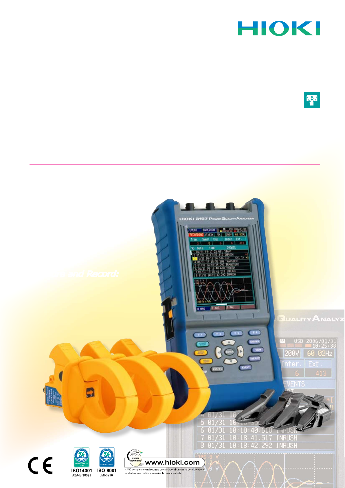
Catch Power Quality Problems on the Fly...
Monitor for:
✔
Inrush Current
✔
Voltage Swells
✔
Voltage Dips
✔
Transient Overvoltage
✔
Interruptions
Measure and Record:
✔
Power and Power Factor
✔
Active/Reactive Energy
✔
Demand
✔
Load Changes
(with graph display!)
✔
Voltage and Current
...Before They Catch You!
Page 2
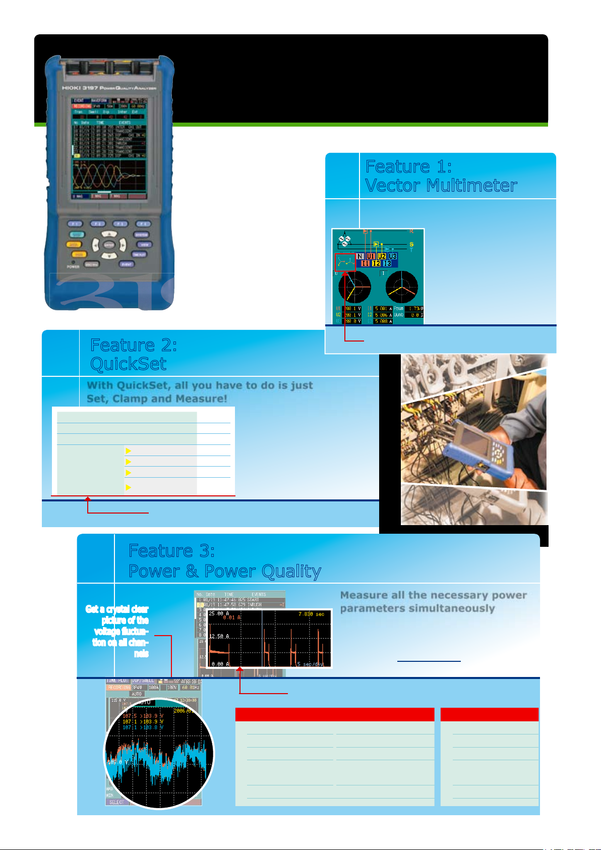
Use the wiring map, vector
map and data monito r to
ch e ck f or p r op e r wi r ing
before taking measurements
– d o n ’ t m i s s o u t o n
impor tant power dat a just
bec a u s e of minor w i r i n g
mistakes!
Vector Multimeter
Feature 1:
2
Measure Power and Power Quality
on Single to Three-Phase Circuits
Quickly and Effortlessly
Q
A
All items are recorded as events so that a quick
understanding can be obtained just by viewing the waveform
With QuickSet, all you have to do is just
Set, Clamp and Measure!
Let QuickSet help you take care
of all the time-consuming setup
procedures. All you nee d to
do is select your circuit, clamp
se nsor and range, and th en
let QuickSet do the rest of the
work for you.
Feature 2:
QuickSet
Testing Parameters Automatically Defi ned by QuickSet
Redefi ne Thresholds Easily with Intuitive Key Panel
Measure all the necessary power
parameters simultaneously
Check for sudden inrush during motor startup
and diagnose breaker trips due to over current
all on the same measurement interface. View
RMS data for every half cycle over a 30 second
period on a large graph display
Feature 3:
Power & Power Quality
Get a crystal clear
picture of the
voltage fl uctua-
tion on all chan-
nels
Power & Energy Power Quality
✓
Voltage
✓
Demand
✓
Inrush Current
✓
Current
✓
Load Changes
✓
Voltage Swells
✓
Frequency
✓
THD(voltage)
✓
Voltage Dips
✓
Power
and Power Factor
✓
Active/Reactive
Energy
✓
Trans ient
Overvoltage
✓
Voltage Fluctuation (dips and swells)
✓
Interruptions
A quick glance at the correct vector map will show you
if your wiring is correct
Line frequency : Auto
Measurement Interval : Auto
Nominal Voltage : Auto
Event
thresholds
against
nominal
voltage
Swell : 110%
Dip : 90%
Interruption : 10%
Transient : ON
Page 3

M
E
A
S
U
R
E
A
3
Convenient Stand for
Hands-free Viewing
Typ e N U1 U2 U3 Region
1
Black Red Yellow Blue Japan, U.K.
2
Blue
Orange
Black Gray EU (new)
3
Black Yellow Green Red China
4
Blue Black Red White EU (former)
5
White Black Red Blue N. A merica
Select from 5 Types of Color-coded
Input Terminal Labels to Suit Your
Application Region
Pull Strap Through
for Ultimate Portability
USB Port for PC
Compatibility
AC Adapter for
Quick Recharge or
Long Recordings
Power Switch
Rugged and Durable Casing to
withstand even the toughest
environments and uses
W
I
R
I
N
G
R
E
C
&
E
V
E
N
T
Setting Up
is as Easy as
1-2-3
W
QuickSet
Use the correct vec-
tor diagram to check that
your wiring is right before
measuring, particularly
useful when measuring
3-Phase circuits
Use QuickSet to automatically set
the default values for line frequency,
nominal voltage, interval, and power
quality thresholds for event detection
Select your
clamp sensor
Select your
wiring
1
2
3
Make detailed
settings on how and
when to measure,
and customize your
level of event
detection as desired.
Toggle between screens
to customize your
measurement settings
WAVEFORM
VECTOR
Monitor
Trends while
Recording
RMS, Phase
Angle and Lead
and Lag
Toggle between
screens using VIEW
key for instantaneous
power data
One-touch switching
between graph and
numerical data
Full-color
waveforms and
RMS readings
Obtain real-time
moving data on
voltage, current,
power, and more!
Page 4

4
ENERGY
Record
and Inspect
(even while measuring)
RMS DIP/SWELL
DEMAND
Auto-Data
Compression Lets You
Record for up to 125
Days
Find the max,
min and average
values for any point
using the cursor
function
Get a detailed picture dur-
ing voltage anomalies -
fl uctuation range for all 3
channels are displayed
Demand Graph
and maximum and
average values
displayed in one
window
✓
Consumed & Regenerated Active Power
✓
Lag and Lead of Reactive Power
Toggle between the trend
graphs for a complete analysis
of the power situation
HARMONICS
DMM
GR A P/L IS T
Harmonic
waveforms of
voltage, current
and active power
to the 50th order
DE TA IL
WAVEFORM
RMS
INRUSH
Identify
Power Quality
Problems
Switch between voltage and
current graphs, and zoom
in on the time axis at the
touch of a button
Display events
AND their waveforms
at the same time
RMS voltage
fl uctuations such
as swells and dips
are clearly displayed
at event detection
Inrush current
fl uctuations are captured
in RMS at a fast 10ms sam-
pling rate and displayed
across a 30-second window
Toggle between
events for a
complete picture of
the power anomaly
Record up to 20
graphs in
internal memory
Store up to
50 Events
"I" marks an
Inrush Event
Scroll down and
select to display the fi ner
details of any event
Page 5

5
Mobility, Portability Plus
Convenient Data Transfer
Right to Your PC
Standard 3197 Package Fulfi lls All the Requirements
for Checking Voltage Anomalies
Carrying
Case
USB Cable
Voltage
Cords
Rechargeable
Battery Pack
PC Application
AC Adapter
To measure current and power, please select one or more of our
HIOKI Clamp On Sensors detailed on the back of this catalog.
nMeasurement Specifications
(Guaranteeed Accuracy Period: 1 Year)
RMS Voltage and Current True RMS (200 ms calculation )
Voltage Accuracy
±0.3% rdg. ±0.2%f.s
Current Accuracy
±0.3% rdg. ±0.2%f.s. + Clamp sensor accurac y
Voltage (1/2) RMS
Measurement
True RMS
(one cycle calculation refreshed every half cycle)
Accuracy
±0.3% rdg. ±0.2%f.s.
Current (1/2) RMS
Measurement
True RMS
(half-cycle calculation, half-cycle voltage synchronized)
Accuracy
±0.3% rdg. ±0.2%f.s. + Clamp sensor accurac y
Frequency Effective Measurement range: 45.00 to 66.00 Hz
Accuracy
±0.01 Hz ±1 dgt.
(when input is at least 10% of range)
Active Power Accuracy
(for consumption and
regeneration)
±0.3% rdg. ±0.2% f.s.
+ clamp-on sensor accuracy (P.F.=1)
Reactive Power Accurac y
(for lags and leads)
±1 dgt. of calculation from each measurement
value
Effect of Power Factor
±1.0% rdg. (50 /60Hz, P.F.=0.5)
Apparent Power Accuracy
±1 dgt. of calculation from each measurement value
Power Factor and
Displacement Power
Factor Accuracy
(leading phase indicated)
±1 dgt. of calculation from each measurement value
(DPF calculated from phase difference between
fundamental voltage and current waveforms)
Active or Reactive Energy
Consumption
Selectable between consumption, regeneration,
lag and lead
Accuracy
±1 dgt. applied to active and reactive power
measurement accuracy
Demand Selectable between active or reactive power
Accuracy
±1 dgt. applied to active and reactive power
measurement accuracy
Harmonic Analysis Orders Up to 50th (2048 points/window, rectangular)
Harmonic Voltage,
Current and Power
Accuracy
(accuracy is not defined
for harmonic power)
1st to 15th order ±0.5% rdg. ±0.2% f.s.
16th to 25th order ±1.0% rdg. ±0.3% f.s.
26th to 35th order ±2.0% rdg. ±0.3% f.s.
36th to 45th order ±3.0% rdg. ±0.3% f.s.
46th to 50th order ±4.0% rdg. ±0.3% f.s.
(add accuracy of clamp sensor to harmonic current accuracy)
Other Measurement
Items
Peak Voltage and Current, K Factor, Voltage
Unbalance Factor, Max/Min/Ave of Time Series
nEvent Detection
Voltage Swells (Rise), Voltage
Dips (Drop), Interruptions
RMS value detected using voltage (1/2) measured
every half c ycle
Inrush Current
RMS value detected using current (1/2) every half cycle
Transient Overvoltage
Detection Range: 50 Vrms (±70.7 Vpeak equiv.) or more, 10 to 100 kHz
Timer Detection
Detect events at preset intervals selectable from
OFF, 1, 5, 15 or 30 minutes; 1, 2 or 12 hours; or 1 day
Manual Detection Detect events when keys are pressed
Thresholds
Set to OFF or to specif ied value, except for
detection of transient overvoltages.
(Waveform
recording not available for transients.)
Event Recording Lengths
Waveform
20ms before detection + 200ms upon detec tion + 30ms after detection
Event voltage fluctuation graph
0.5s before + 2.5s after detection
Inrush current graph
0.5s before + 29.5s after detection
Maximum Number of
Recordable Events
50 event waveforms, 20 event voltage fluctuation
graphs, 1 inrush current graph, 1000 event counts
nInput Specifications
Wiring Configurations
Single-phase 2-wire (1P2W), single-phase 3-wire
(1P3W), three-phase 3-wire (3P3W2M and 3P3W3M),
three-phase four-wire (3P4W and 3P4W2.5E)
Measurement Line frequency
Auto-select (50/60 Hz)
Maximum Allowable Input
Voltage
Voltage input terminal:
780 V AC (1103 Vpeak)
Current input terminal:
1.7 V AC (2.4 Vpeak)
Maximum Rated Voltage
to Ground
Voltage input terminal: CATIII 600 V AC, CATIV 300 V AC (50/60 Hz)
Current input terminal:
per clamp-on sensors used
Measurement Method
Simultaneous digital sampling of voltage and current
(sampling frequency: 10.24 kHz per channel)
Voltage Measurement
Range
600.0V (Crest factor 2 or less)
Current Measurement
Range:
Manual ranging
according to clamp sensor
(Crest factor 3 or less)
Clamp Sensor
Range
Clamp Sensor
Range
9657-10, 9675
500.0 mA /5.000 A
9661, 9667 (500A)
50.00 A/500.0 A
9694, 9695-02 5.000 A/50.000 A 9669 100.0 A/1.000 kA
9660, 9695-03 10.00 A/100.0 A 9667 (5000A) 500.0 A/5.000 kA
Power Measurement
Range:
Depends on
combination of current range
and measurement line
500mA
300.0W/600.0W/900.0W
100A
60.00kW/120.0kW/180.0kW
5A
3.000kW/6.000kW/9.000kW
500A
300.0kW/600.0 kW/900.0k W
10A
6.000kW/12.00kW/18.00kW
1kA
600.0kW/1.200MW/1.800MW
50A
30.00kW/60.00kW/90.00kW
5kA
3.000MW/6.000MW/9.000MW
A PQA that TRULY fi ts in the palm of your hand.
6 Hours of Continuous
Use on a Single Recharge
Non-volatile Ni-MH rechargeable
ba t t e r y pack keeps impor t ant
measur ement dat a in memor y
even after power is turned off.
Feature 5:
Compact Design
Makes for Long Battery Life
Connect to
multiple 3197 units
simultaneously
using a USB hub
Two Integrated Programs for
Data Download and Viewing
Sta n d ar d USB c o nn ect i o n le t s you
d o w n l o a d d a t a a t a s n a p , an d
immediately view your measurements
with the DataViewer
Feature 4:
Bundled PC Application
Software
Open downloaded recordings with DataViewer to manage
and process your captured power data on your PC.
Event List
Event Details
Time Plot Graph
Event Waveform
Settings
Page 6

nBASIC SPECIFICATIONS
Display 4.7-inch color STN LCD
Display languages English, Japanese or Chinese (Simplified)
Display refresh rate Approx. once per second
Clock functions Auto calendar, auto leap year, 24-hour format
Real-Time Clock accuracy Within 13 seconds/month
Internal Memory Capacity 4MB
Maximum recording time 125 Days
Interval Settings
Demand period 15 min., 30 min. and 1 hour
Recordable Items All parameters (incl. max/min/average values)
AUTO, 1, 5, 15 and 30 min., and 1 hour (AUTO
sequentially selects 1, 2, 10, 30 seconds, 1, 5, 15
and 30 min., and 1 hour automatically)
nINTERFACE SPECIFICATIONS
Interface USB 2.0 (Full Speed)
Connection destination Computer operating on Windows 2000/XP
nENVIRONMENTAL AND SAFETY-RELATED SPECIFICATIONS
Operating
environment
Temperature
and humidity
Applicable
standards
Power source
Continuous
operating time
with battery pack
Dimensions and
mass
Indoors, up to 2000 m (6562-ft.) ASL
Storage
Operation
Safety
EMC
AC Adapter 9418-15 or Battery Pack 9459
(Maximum rated power: 23 VA (with AC adapter)
Approx. 6 hours
(after full charge, with 5 min. auto-off LCD backlight)
128 W × 246 H × 63 D mm (5.04”W × 9.69”H × 2.48”D)
(including stand)
Approx. 1.2 kg (42.3 oz.) (with battery pack)
-10 to 50°C (14 to 122°F), 80% RH or less
0 to 40°C (32 to 104°F), 80% RH or less
EN61010, Pollution degree 2,
Measurement Categories III (600 V) and IV (300 V)
(anticipated transient overvoltage 6000 V)
EN61326 Class A
EN61000-3-2, EN61000-3-3
(non-condensating)
(non-condensating)
nCLAMP ON SENSOR SPECIFICATIONS
9694 9660 9661 9669 9667 9695-02 9695-03
3m cord 3m cord
MODEL
CAT III
300V
Measur able con ducto r diameter
Primary current rating
Output voltage AC 10mV/A AC 1mV/A AC 1mV/A AC 0.5mV/A AC 500mVf.s. AC 10mV/A AC 1mV/A
Amplitude
(45 to 66 Hz)
Accuracy
Frequency characteristic
(accuracy deviatio n)
Max. rated volta ge to
earth (insulated con ducto r)
Maximum allowable
input (45 to 66 Hz)
Dimensions and weight
Phase
(5Hz to 5kHz)
Requirements
AC 5A AC 100A AC 500A AC 1000A AC 500A/5000A AC 50A AC 100A
±0.3%rdg.±0.02%f.s. ±0.3%rdg.±0.02%f.s.
within ±2° within ±1° within ±0.5° within ±1°
300Vrms 300Vrms 600Vrms 600Vrms 1000Vrms 300Vrms
50A continuous 130A continuous 550A continuous 1000A continuous 10000A
46W×135H×21Dmm, 230g 46W×135H×21Dmm, 230g 77W×151H×42Dmm, 360g
CAT III
300V CAT III
15mm
φ
within ±1.0% at 40Hz to 5kHz (9669: within ±2.0%)
nCOMPLETE LIST OF OPTIONS
CLAMP ON SENSOR (100A)
CLAMP ON SENSOR (500A)
FLEXIBLE CLAMP ON SENSOR (5000A)
CLAMP ON SENSOR (1000A)
CLAMP ON SENSOR (5A)
CLAMP ON SENSOR (50A)
CLAMP ON SENSOR (100A)
CONNECTION CORD
(for the 9695-02/9695-03)
CLAMP ON LEAK SENSOR (10A)
CLAMP ON LEAK SENSOR (10A)
VOLTAGE CORD
(bundled with the standard 3197)
AC ADAPTER (bundled with the standard 3197)
BATTERY PACK (bundled with the standard 3197)
PQA-HiVIEW Pro
PC Application Software
n3197 STANDARD BUNDLE CONFIGURATION
Includes all the equipment you need to measure voltage.
For current or power measurements, please select from our wide
assortment of clamp on sensors.
VOLTAGE CORD 9438-05 (3m cord length), BAT TERY PACK 9459, AC
ADAPTER 9418
-15 , USB Cable, Input Terminal Labels, Input Cord
Labels, 3197 Applications PC Program (CD-ROM), strap, carrying case,
measurement guide, instruction manual
HIOKI ( Sha nghai) Sales & Tradin g Co., Ltd. :
1904 Shanghai Ti mes Squ are Of fice, 93 H uai Hai Z hong Ro ad
Shang hai, P.R.China POSTC ODE: 20 0021
TEL +86 -21-6391-009 0/0 092 FAX + 86-21-6391-03 60
E-mail : info-sh@hioki.cn
HEAD O FFICE :
81 Koizumi, Ue da, Nagano, 386-1192, Japan
TEL +81-268-28-0562 / FAX +81-268-28-0568
E-mail: os-com@hioki.co.jp
HIOKI USA CORP ORATION :
6 Corporate Drive, Cranb ury, NJ 08512 USA
TEL +1-609-40 9-9109 / FAX +1-609-409-9108
E-mail: hioki@hiokiusa.com
All in format ion corr ect as of Jun. 16, 20 08. All sp ecicat ions ar e subject to ch ange witho ut notice. 3197E4-86 M-02K P rint ed in Japa n
Beijing Office :
A-2602 Freetown, 58 Don g San Huan Nan Ro ad
Beijing, P.R.China POSTCODE: 10002 2
TEL +86 -10-5867-4080/40 81 FAX +86 -10-5867-4090
E-mail : info-bj@hioki.cn
Guang zhou Office :
Room 303, Profit Pla za, No.76, West H uangpu Road
Guang zhou, P.R.China PO STCODE: 510623
TEL +86 -20-38 392673/2676 FA X +86-20 -3839 2679
E-mail : info-gz@hioki.cn
9660
9661
9667
9669
9694
9695
9695-03
9219
9657
9675
9438
9418-15
9459
9624-50
3m cord
600V
46mm
φ
±0.3%rdg.±0.01%f.s. ±1.0%rdg.±0.01%f.s.
φ
3m cord CAT III 1000V
CAT III
600V
55mm, 80×20mm
100W×188H×42Dmm, 590g Sensor length 910mm, 140 g
MODEL
Measurable conductor diamete r
-02
-10
-05
Primary current rating
Output voltage AC 100mV/A AC 100mV/A
Amplitude Accuracy
(45 to 66 Hz)
Phase Accuracy (50/60Hz)
Residual Curren t
Frequency characteristic
(accuracy deviation)
Max. rated volta ge to ear th
Maximum allowable inp ut
Dimensions and we ight
Notes
nSUGGESTED OPTIONS for POWER MEASUREMENTS
3P4W Circuit testing of motors and breakers:
3197 Standard Package + 9661 (500A Sensor)×3
3P4W Circuit testing of external CTs:
3197 Standard Package + 9694 (5A Sensor)×3
3P Leakage testing:
3197 Standard Package + 9675 (10A Sensor)×3
DISTRIBUTED BY
2m from sens or to circu it
1m from circui t to connec tor
254mm
φ
±2.0%rdg.±1.5mV
within ±1°
(minimum 10% input)
±3dB at 10Hz to
20kHz
continuous
CAT III
300V CAT III
15mm
φ
±0.3%rdg.±0.02%f.s.
within ±2° within ±1°
within ±1.0% at 40Hz to 5kHz
60A continuous 130A continuous
300V
±0.3%rdg.±0.02%f.s.
51W×58H×19Dmm, 50g
9445-02 /03 AC Adapter (Option)
9219 Connection Cord (3m; Option)
9675 9657-10
3m cord
CAT III
300V
30mm
φ
AC 10A AC 10A
±1.0%rdg.±0.005%f.s. ±1.0%rdg.±0.05%f.s.
within ±5° within ±3°
(10A on forward and return)
1mA
within ±5% at 40Hz to 5kHz within ±3% at 40Hz to 5kHz
300Vrms (insulated conductor)
10A continuous 30A continuous
60W×113H×24Dmm, 160g 74W×145H×42Dmm, 380g
Not compatible with power measurements
3m cord
CAT III
300V
40mm
φ
(100A on forward and return)
5mA
 Loading...