

Page 1

Instruction Manual
3194
MOTOR/HARMONIC
HiTESTER
June 2011 Revised edition 6 3194A981-06 11-06H
Page 2

Page 3

Contents
Introduction i
Inspection ii
Safety Notes iv
Notes on Use vii
Chapter 1 Overview 1
1.1 Product Overview 1
1.2 Features
Chapter 2 Names and Functions of Parts 5
2.1 Panels and Key Operation 5
2.2 Names and Configuration of Screen
2.2.1 Screen Configuration 8
2.2.2 MEAS Screen (Measurement Screen) 9
2.2.3 STATUS Screen (Setting Screen) 13
2.2.4 FDD Screen 16
2.3 Indicators 17
2.4 Peak Over Indication
18
Chapter 3 Preparation for Measurement 19
3.1 Notes on Use 19
3.2 Basic Operating Procedure
3.3 Powering On
22
23
2
8
3.4 Connecting the Direct Input Unit
3.5 Connecting the Clamp Input Unit
3.6 Measurement Losses
3.7 Error Messages
3.8 System Reset
3.9 Operations During Power Failure
24
26
27
28
29
30
Chapter 4 Setting and Using the Basic Functions 33
4.1 Setting the Wiring Mode (1P2W to 3P4W) 33
Page 4

4.2 Setting the Coupling Mode (DC/AC+DC/AC) 36
4.3 Switching the Voltage Range and Current Range
37
4.4 Effective Value (RMS) or Mean Rectified Value
(MEAN) Selection
4.5 Setting the Scaling (PT/CT/SC Ratios)
4.6 Setting the Low-pass Filter (LPF)
4.7 Setting the Phase Polarity Discrimination Filter
4.8 Switching the Waveform Peak Value
4.9 Setting the Response (FAST/MID/SLOW)
4.10 Setting the Averaging
4.11 Setting on the MEAS Screen
4.11.1 Setting the Display Items (for 1 to 6 channels) 50
4.11.2 Setting the SELECT screen 51
39
40
42
43
44
45
46
50
4.12 Setting on the SYSTEM screen 52
4.12.1 Switching the Interface (GP-IB/RS-232C) 52
4.12.2 Setting the Display Color 53
4.12.3 Setting the Back Light 53
4.12.4 Setting the Equation for Reactive Power (Q)
and Apparent Power (S) 54
4.12.5 Setting the Beep Sound 55
4.12.6 Setting Indications for Out-of-Range Inputs 55
4.12.7 Setting the Display Language (English/Japanese) 56
4.12.8 Setting the Real-time Clock 56
4.13 Degaussing 57
Chapter 5 Frequency Measurement 59
5.1 Setting the Frequency Measurement Source (fa) 60
5.2 Setting the Frequency Range(fa)
61
Chapter 6 Hold/Peak Hold Function 63
6.1 Hold Function 63
6.2 Peak Hold Function
6.2.1 Combination with Control Times 66
65
Chapter 7 Integration Function 67
7.1 Overview 67
7.2 Setting the Control Time
7.2.1 Setting the Interval Time 69
7.2.2 Setting the Timer 70
7.2.3 Setting the Real Time Control 71
69
Page 5

7.3 Integration Screen 72
7.4 Starting, Stopping, and Resetting the Integration
7.5 Manual Integration
(Controlled by Panel Keys)
74
73
7.6 Integration Using Time Settings
(Controlled by Panel Keys)
7.6.1 Timer Integration 75
7.6.2 Real-Time Control Integration 76
7.6.3 Interval Integration 76
75
7.7 Measuring the Load Factor 77
7.8 Zero suppress function
78
Chapter 8 Efficiency Measurement 79
8.1 Overview 79
8.2 Efficiency Screen
8.3 Setting the Calculation Formula
8.4 Example Measurement
8.4.1 Efficiency Measurement of a Switching Power
Supply (1φ2W) 82
80
81
82
8.4.2 Efficiency Measurement of a Switching Power
Supply (3φ3W) 82
8.4.3 Efficiency Measurement of a Light Fitting
(Two-Lamp) 83
8.4.4 Efficiency Measurement of an Inverter (1φ2W) 83
8.4.5 Efficiency Measurement of an Inverter (3φ3W)
and Motor 84
Chapter 9 External Output/ External Control Terminals 85
9.1 Connector Pin Arrangement 86
9.2 Internal Circuit for Analog, Monitor, D/A Outputs
9.3 Internal Circuit for the External Control and Timing
9.3.1 INTEG.EXT.CONT and INTEG.RESET Terminals 88
9.3.2 FDD/PRINTER.START Terminal 89
9.3.3 EXT.A/D START Terminal 89
87
88
Chapter 10 D/A Output 91
10.1 Overview 91
10.2 Selecting Output Item
10.3 Output Rate
92
93
Chapter 11 Using the Floppy Disk Drive 95
11.1 Overview 95
Page 6

11.2 Operation Procedure 96
11.3 Using the Floppy Disk
11.4 Formatting a Floppy Disk
11.5 Switching the FDD/Printer
11.6 Setting File Names for Saved Measurement Data
11.7 Setting the Measurement Items for Saving
11.8 Saving the Data on FDD
11.8.1 Automatic Saving Using Time Settings 102
11.8.2 Manual Saving 103
11.8.3 Screen Hard Copy 103
11.8.4 Saving the Settings 103
11.8.5 Saving and Loading Settings 104
97
98
99
100
101
102
11.9 Information Which Can Be Saved 105
11.10 Deleting and Confirming Files
11.11 Format for Data Output to Floppy Disk
11.12 Message and Error Displays
106
107
108
Chapter 12 GP-IB and RS-232C Interface 109
12.1 Overview 109
12.2 Specifications
12.2.1 GP-IB Interface 110
12.2.2 RS-232C Interface 111
12.3 Interface Outline 114
12.3.1 Messages 114
12.3.2 Command Syntax 115
12.3.3 Headers 115
12.3.4 Message Terminators 116
12.3.5 Separators 116
12.3.6 Data Formats 117
12.3.7 Abbreviation of Compound Commands 118
12.3.8 Output Queue 119
12.3.9 Input Buffer 119
12.3.10 Note on Commands Initiating Events 119
12.3.11 Status Model 120
110
12.3.12 Status Byte Register 121
12.3.13 Event Registers 122
12.3.14 GP-IB Commands 129
12.4 Command Reference 130
12.4.1 Standard Command 131
12.4.2 Specific Commands 141
Page 7

12.5 Command Summary 195
12.5.1 Standard Commands 195
12.5.2 Commands Specific to the 3194 196
12.5.3 Valid Command According to Condition
(Standard Command) 202
12.5.4 Valid Command According to Condition
(Specific Command) 203
12.5.5 Execution Time of GP-IB Interface Command 208
12.5.6 Initialization 209
12.5.7 Specific Command Tree 210
12.6 Sample Programs 213
12.6.1 GP-IB 213
12.6.2 RS-232C 214
12.7 Device Compliance Statement 215
12.8 Notes on Interface
12.8.1 GPーIB Troubleshooting
12.8.2 RS-232C Troubleshooting
217
217
218
Chapter 13 Using the Printer (Option) 219
13.1 Overview 219
13.2 Specifications
13.3 Operating Procedure
13.4 Loading Recording Paper
13.5 Switching the FDD/Printer
13.6 Setting the Measurement Items to Print
13.7 Printing Out
13.7.1 Manual Printing 225
13.7.2 Automatic Printing by Time Settings 225
13.7.3 Screen Hard Copy 227
13.7.4 Help Printing Mode 227
220
221
222
223
224
225
13.7.5 External Control Printing 227
13.8 Setting the Printing Direction 228
13.9 Error and Overflow Displays
229
Chapter 14 9600 AC/DC DIRECT INPUT UNIT (Option) 231
14.1 Overview 231
14.2 Notes on Use
14.3 Specifications (using with the 3194)
14.4 Internal Block Diagram
14.4.1 RMS Value (root-mean-square value) 236
232
233
236
Page 8

14.4.2 MEAN Value (MEAN rectification effective value for
display) 237
14.4.3 Active Power 237
14.4.4 Waveform Peak Value Measurement Circuit 238
14.4.5 Crest Factor 238
Chapter 15 9601 AC DIRECT INPUT UNIT (Option) 239
15.1 Overview 239
15.2 Notes on Use
15.3 Specifications (using with the 3194)
15.4 Internal Block Diagram
240
241
244
Chapter 16 9602 AC/DC CLAMP INPUT UNIT (Option) 245
16.1 Overview 245
16.2 Notes on Use
16.3 Specifications (using with the 3194)
16.4 Internal Block Diagram
246
247
250
Chapter 17 Maintenance and Service 251
17.1 Cautions 251
17.2 Disposing of the Unit
252
Chapter 18 Rack Mounting 253
18.1 Rack Mounting Fittings 253
18.2 Installation Procedures
255
Chapter 19 Specifications (unit only) 257
19.1 General Specifications 257
19.2 Function Specifications
19.3 Calculations
19.4 Internal Block Diagram of the 3194
260
266
271
Appendix APPENDIX 1
Index INDEX 1
Page 9

────────────────────────────────────────────────────
Introduction
Thank you for purchasing this HIOKI "3194 MOTOR/HARMONIC
HiTESTER."
To get the maximum performance from the unit, please read this manual
first, and keep this at hand.
i
────────────────────────────────────────────────────
Introduction
Page 10

ii
────────────────────────────────────────────────────
Inspection
When the unit is delivered, check and make sure that it has not been
damaged in transit. In particular, check the accessories, panel switches, and
connectors. If the unit is damaged, or fails to operate according to the
specifications, contact your dealer or HIOKI representative.
■ Standard accessories
Instruction Manual (For the 3194 main unit) 1
(For the 9605-01) 1
Power cord 1
Connector 1
■Options
9600 AC/DC DIRECT INPUT UNIT
9601 AC DIRECT INPUT UNIT
9602 AC/DC CLAMP INPUT UNIT
9603-01 EXTERNAL SIGNAL INPUT UNIT
9604 PRINTER UNIT
9605-01 HARMONIC MEASURMENTS UNIT (Standard installation)
────────────────────────────────────────────────────
Inspection
Page 11

iii
────────────────────────────────────────────────────
■ Shipment
If reshipping the unit, preferably use the original packing.
Before shipping the unit, always remove the floppy disk.
ACDC UNIT
AC UNIT
CLAMP UNIT ACDC 20 A
CLAMP UNIT ACDC 200 A
CLAMP UNIT ACDC 500 A
CLAMP UNIT ACDC 50 A
CLAMP UNIT AC 20A CLAMP
CLAMP UNIT AC 200A CLAMP
9603-01 ON
Printer ON
9605-01 ON
9600 is installed.
9601 is installed.
9602 is installed and 9277 is inserted.
9602 is installed and 9278 or CT6863 is inserted.
9602 is installed and 9279 or 9709 or CT6865 is
inserted.
9602 is installed and CT6862 is inserted.
9602 is installed and 9270 or 9272 (20 A), 9272-10
(20 A) is inserted.
9602 is installed and 9271 or 9272 (200 A), 9272-10 (200
A) is inserted.
9603-01 is installed.
9604 is installed.
9605-01 is installed. (Standard installation)
────────────────────────────────────────────────────
Inspection
Page 12

iv
────────────────────────────────────────────────────
Safety Notes
This Instruction Manual provides information and warnings essential for
operating this equipment in a safe manner and for maintaining it in safe
operating condition. Before using this equipment, be sure to carefully read
the following safety notes.
DANGE R
Safety symbols
This instrument is designed to comply with IEC 61010 Safety
Standards, and has been thoroughly tested for safety prior to
shipment. However, mishandling during use could result in injury or
death, as well as damage to the instrument. Be certain that you
understand the instructions and precautions in the manual before
use. We disclaim any responsibility for accidents or injuries not
resulting directly from instrument defects.
・ This symbol is affixed to locations on the equipment where the
operator should consult corresponding topics in this manual
(which are also marked with the symbol) before using relevant
functions of the equipment.
・ In the manual, this mark indicates explanations which it is
particularly important that the user read before using the
equipment.
Indicates AC (Alternating Current).
Indicates both DC (Direct Current) and AC (Alternating Current).
DANGE R
WARNING
CAUTION
NOTE
Indicates a grounding terminal.
Indicates the ON side of the power switch.
Indicates the OFF side of the power switch.
The following symbols are used in this Instruction Manual to indicate the
relative importance of cautions and warnings.
Indicates that incorrect operation presents extreme danger of
accident resulting in death or serious injury to the user.
Indicates that incorrect operation presents significant danger of
accident resulting in death or serious injury to the user.
Indicates that incorrect operation presents possibility of injury to
the user or damage to the equipment.
Denotes items of advice related to performance of the equipment
or to its correct operation.
────────────────────────────────────────────────────
Safety Notes
Page 13

v
────────────────────────────────────────────────────
Accuracy
The specifications in this manual include figures for "measurement accuracy"
when referring to digital measuring instruments, and for "measurement
tolerance" when referring to analog instruments.
・f.s. (maximum display or scale value, or length of scale)
Signifies the maximum display (scale) value or the length of the scale (in
cases where the scale consists of unequal increments or where the maximum
value cannot be defined).
In general, this is the range value (the value written on the range selector or
equivalent) currently in use.
・rdg. (displayed or indicated value)
This signifies the value actually being measured, i.e., the value that is
currently indicated or di splayed by the measuring instrument.
・dgt. (resolution)
Signifies the smallest display unit on a digital measuring instrument, i.e., the
value displayed when the last digit on the digital display is "1".
Display items Display items FDD (header) Printer GP-IB/RS-232C
Voltage
Voltage peak
Current
Current peak
Active power
Reactive power
Apparent power
Power factor
Phase angle
Frequency
Integration active
current
Integration power
|Up|/Pk (enlarged
|Ip|/Pk (enlarged
(+) +Ih PIh Ih (+) PIH
(-) -Ih MIh Ih (-) MIH
(total)
(+) +WP PWP WP (+) PWP
(-) -WP MWP WP (-) MWP
(total) WP WP WP WP
U U U U
display)
I I I I
display)
P P P P
Q Q Q Q
S S S S
λ PF PF PF
φ DEG DEG DEG
f f f f
Ih Ih Ih IH
PEAK PEAK (Vpeak) Pk
PEAK PEAK (Apeak) Pk
Load factor
Maximum averaging
power
Efficiency
Channel A of 9603-01
Channel B of 9603-01
Motor power of 9603-01
────────────────────────────────────────────────────
LF LF LF LF
no display Wmax Wmax none
η EFFI EFFI EFF
chA CHA CHA EXTA
chB CHB CHB EXTB
Pm PM PM PM
Safety Notes
Page 14
vi
────────────────────────────────────────────────────
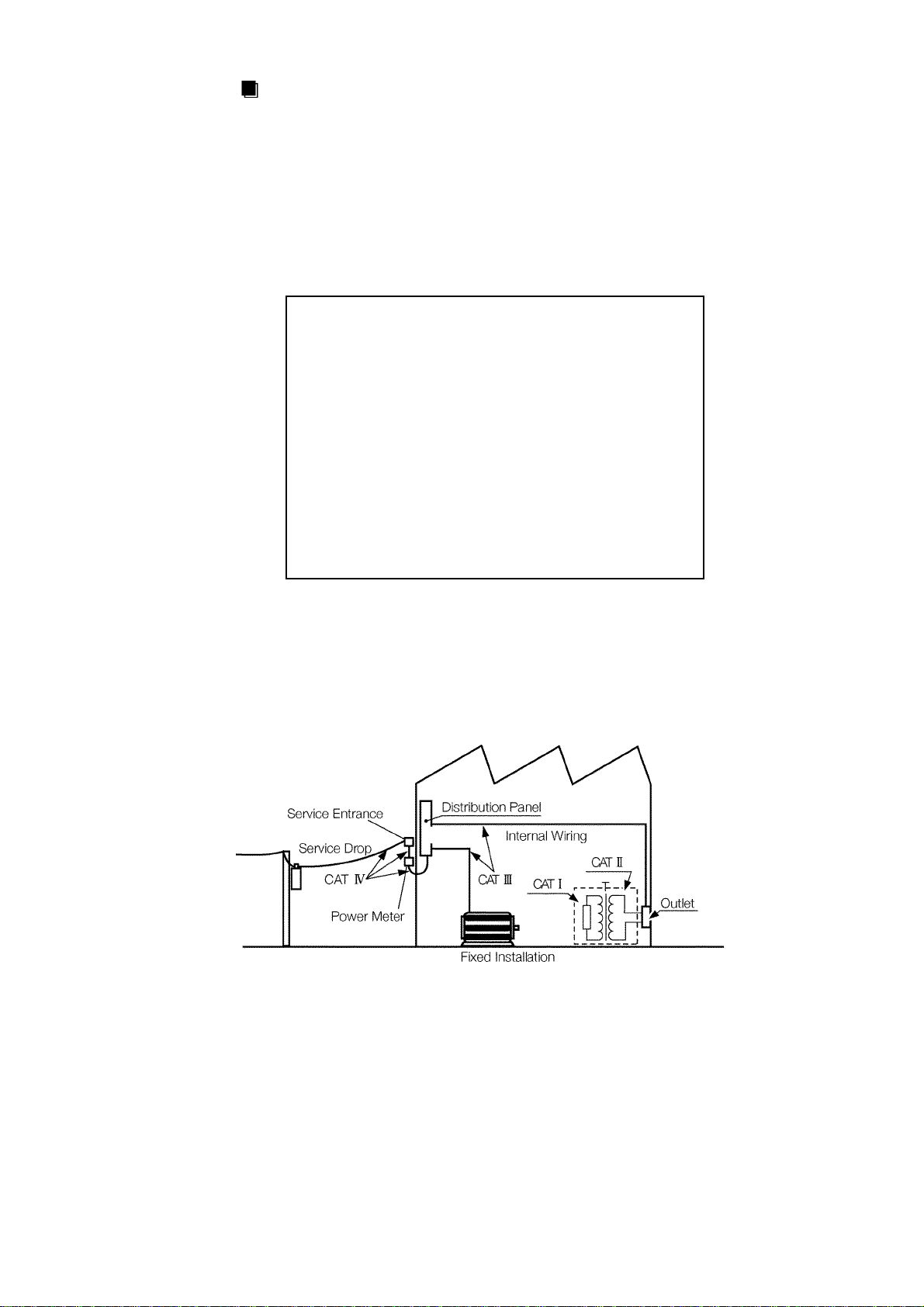
Measurement categories (Overvoltage categories)
9600, 9601 and 9602 instrument comply with CAT III (600 V or less)/ CAT
II (600 to 1000 V) safety requirements.
9603-01 instrument complies with CAT I safety requirements.
To ensure safe operation of measurement instruments, IEC 61010 establishes
safety standards for various electrical environments, categorized as CAT I to
CAT IV, and called measurement categories.
CATⅠ
CATⅡ
CATⅢ
CATⅣ
Secondary electrical circuits connected to an AC
electrical outlet through a transformer or similar
device.
Primary electrical circuits in equipment connected to
an AC electrical outlet by a power cord (portable
tools, household appliances, etc.)
CAT II covers directly measuring electrical outlet
receptacles.
Primary electrical circuits of heavy equipment (fixed
installations) connected directly to the distribution
panel, and feeders from the distribution panel to
outlets.
The circuit from the service drop to the service
entrance, and to the power meter and primary
overcurrent protection device (distribution panel).
Using a measurement instrument in an environment designated with a
higher-numbered category than that for which the instrument is rated could
result in a severe accident, and must be carefully avoided.
────────────────────────────────────────────────────
Safety Notes
Page 15
vii
────────────────────────────────────────────────────
Notes on Use
In order to ensure safe operation and to obtain maximum performance from
the unit, observe the cautions listed below.
DANGE R
WARNING
Always connect the powermeter input (including clamp) to the
secondary side of the breaker. On the secondary side of a breaker,
even if the lines are shorted the breaker can trip and prevent an
accident. On the primary side, however, the current capacity may be
large, and in the event of a short-circuit there may be a serious
accident.
The maximum input voltage and current for this unit depend on the
input unit being used. Do not apply an input exceeding the maximum
input voltage and current specified for the input unit. Exceeding the
maximum input voltage or current could damage the unit or cause a
serious accident.
Before turning on the power, make sure that the voltage of the power
supply being used matches the supply voltage indicated on the rear
panel of the unit. If an attempt is made to use an improper supply
voltage, there is danger of damage to this unit and of life-threatening
risk to the operator.
The power switch has a microgap construction, and it is therefore
essential to use it close to a power outlet. When the unit is not in
use, and while making connections to the circuit being tested, isolate
the unit electrically from the power supply, for example by removing
the power cord plug from the outlet.
The unit is constructed so as to be connected to a ground line via a
three-core power cord that is supplied with the unit. In order to avoid
electric shock, connect the unit to a properly grounded (3-pin) outlet
using the power cord provided.
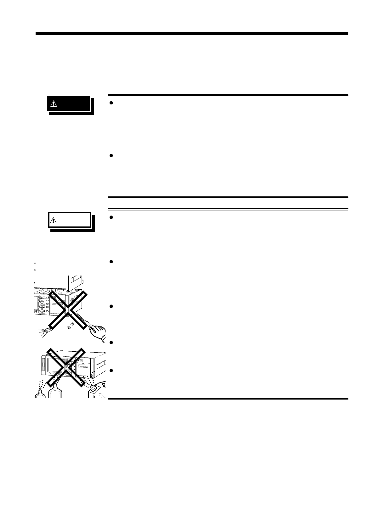
Do not remove the case of the unit. There are components inside
carrying high voltages or becoming hot, and this could cause an
electric shock accident.
Do not use the unit where it may be exposed to corrosive or
explosive gases. The unit may be damaged, or explosion may occur.
────────────────────────────────────────────────────
Notes on Use
Page 16
viii
────────────────────────────────────────────────────
CAUTION
・ Should the unit emit smoke, or a strange smell or strange sound,
immediately stop testing operations, power the unit off, and remove
the power cord from the outlet, shut off the circuit being tested,
disconnect the unit, and consult your HIOKI representative.
Continued use of the unit could lead to fire or electric shock
accidents.
・ Do not insert foreign objects through the ventilation holes in the top
and bottom of the case. Particularly if metallic, liquid, or combustible
substances get inside the case, this may lead to fire or electric
shock, or to malfunction.
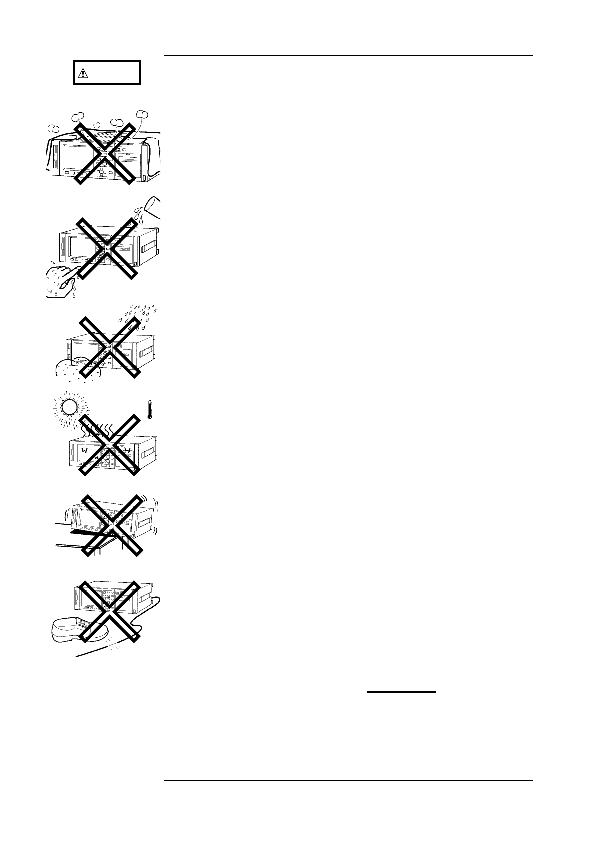
・ Never allow the ventilation holes in the top and bottom covers to
become blocked while using this unit. Blocking the ventilation will
cause internal temperature to rise, possibly resulting in fire or
damage to the equipment.
・ To prevent electric shock, do not allow the unit to become wet and
do not use the unit when your hands are wet.
・ This unit is designed for indoor use and can be safely used at
temperatures ranging from 0℃ to 40℃ and should be operated at
80% RH or less.
・ This unit is not constructed to be waterproof or dustproof, so do
not use it in a very dusty environment or in one where it will get
wet.
・ Do not store or use the unit where it will be exposed to direct
sunlight, high temperatures, high humidity, or condensation. If
exposed to such conditions, the unit may be damaged, the insulation
may deteriorate, and the unit may no longer satisfy its
specifications.
・ To avoid damage to the unit, do not subject the equipment to
vibrations or shocks during transport or handling. Be especially
careful to avoid dropping the equipment.
・ Do not place the unit on an unstable stand, or in an uneven
location. It may fall to the ground, or fall over, and either of these
events may lead to malfunction or accident.
・ Do not use the unit near any device which generates strong
electromagnetic radiation or near a static electrical charge, as these
may cause errors.
・ Avoid treading on or pinching the cable so as not to damage the
cable sheaths.
・ When unplugging the power cord from the power receptacle or from
the unit, grasp the plug, not the cord, in order to avoid damaging the
cable.
・ To avoid damaging the sensor cables or probes, do not bend or pull
them, especially where they connect to the sensor.
・ Use caution when taking measurements in circuits where the power
line are hot.
・ Keep the cables well away from heat, to prevent the possibility of
melting the insulation.
・ For long-term storage, remove the power cord.
────────────────────────────────────────────────────
Notes on Use
Page 17

ix
────────────────────────────────────────────────────
NOTE
・ All options for this unit are factory-fitted, but it is also possible to add
options at a later date after purchase. In this case, however, it is necessary
for the unit to be returned to HIOKI headquarters.
・ With the appropriate combination of direct connection input units, this unit
can function as either an AC power meter or dual AC/DC power meter.
When used together with clamp input units, depending on whether the clamp
sensor used is for AC or DC, this unit can function as either an AC power
meter or dual AC/DC power meter. When used as an AC power meter, it is
not possible to measure a DC component superimposed on the AC signal
(half-wave rectification, or full-wave rectification upper and lower excluded
waveform).
・ Note that limits are specified for the range in which voltage and current level
accuracies are guaranteed.
・ In order to assure accurate measurements, allow this unit to warm up for at
least 1 hour before using it.
・ This power meter uses the calculations indicated in the specifications in
order to determine apparent power (S), power factor (
λ
), and reactive power
(Q) on the basis of the measured voltage (U), current (I), and active power
(P). The values displayed by this power meter may differ from those
produced by other testers that are based on different principles of operation
or testers that use different calculations.
・ Display of a polarity symbol (-) together with reactive power (Q), power
factor (λ) or phase angle (φ) occurs only when TYPE1 is selected as the
calculation type, and indicates that current is delayed with respect to
voltage. For reasons related to circuit design, the polarity symbol is
displayed even when input is "0".
・ Due to measuring error or a disproportionate load, the effective power may
exceed the apparent power, resulting in a power factor of 1 or more. In such
a case, this system is designed to make the apparent power equal to the
effective power.
・ There are two sorts of measurement: using analog calculation by the input
unit or by digital calculation using the harmonic analysis/flicker
measurement function, and since these have entirely different principles of
measurement, frequency range, and accuracy, and as a result the final
measured values may be different.
・ Accurate measurement may be impossible in locations subject to strong
external magnetic fields, such as transformers and high-current conductors,
or in locations subject to strong external electric fields, such as radio
transmission equipment.
・ For the current measurement of the 9600 AC/DC DIRECT INPUT UNIT, the
DC-CT (current transformer) method is used, so after measuring a large
current, there may be a very slight residual offset signal. The offset signal
produces the largest error effect in the minimum ranges; in this case, shut
off the current input, and carry out degaussing (DMAG).
・ The 9600, 9601, and 9602 active power measurement units operate with an
auto-zero circuit at 2.442 kHz. For this reason, an input signal with a
frequency of 2.442 kHz will result in a periodically fluctuating display
indication.
────────────────────────────────────────────────────
Notes on Use
Page 18

x
────────────────────────────────────────────────────
NOTE
・ When the input is less than a certain level of measurement range, depending
on using the input unit, the display value is forced to zero. See the
specifications of the input unit to be used.
・ When measuring a high frequency voltage to earth (for example the
secondary side of an inverter), errors may occur in the measurement values.
・ To maintain the measurement accuracy of the unit, bear the following
cooling measures in mind:
Do not obstruct the ventilation holes
Keep away from sources of heat
If rack mounted, install a cooling fan
・ This unit switches the power supply voltage automatically. Voltage
fluctuations of 10% from the rated supply voltage are taken into account.
・ This unit has no external fuse. Thus if the unit does not operate when the
power switch is turned on and power is supplied, there is a fault. Disconnect
the power cord and measurement lines, and contact your dealer or HIOKI
representative.
・ This instruments may cause interference if used in residential areas. Such
use must be avoided unless the user takes special measures to reduce
electromagnetic emissions to prevent interference to the reception of radio
and television broadcasts.
────────────────────────────────────────────────────
Notes on Use
Page 19

1
────────────────────────────────────────────────────
Chapter 1
1
2
1.1 Product Overview
This instrument is a power meter suitable for comprehensive device
assessment of motors and inverters. The power meter accommodates up to
six input units and it supports from single-phase to 3-phase inverter and
motor systems. The meter has the harmonic analysis function as standard
equipment, which enables an analysis including carrier components not only
fundamental waves.
This power meter is provided with an optional function to obtain a torque
signal directly from a torque sensor and calculate motor power and motor
efficiency. The meter also has many other optional functions to suit various
measurement applications.
For the harmonic analysis function, please see the operations manual of the
9605-01 HARMONIC MEASUREMENTS UNIT.
Overview
3
4
5
6
7
8
9
10
11
12
13
14
A
────────────────────────────────────────────────────
1.1 Product Overview
Page 20

2
────────────────────────────────────────────────────
1.2 Features
(1) Simultaneous measurement of multiple systems
Up to six input units can be installed on the meter and you can measure the
input and output of a 3-phase inverter with only one meter.
(2) Harmonic analysis up to 3000th harmonic
The power meter is capable of conducting an analysis including carrier
frequencies, not only the fundamental frequencies like those on the
secondary side of an inverter. This enables an analysis of a loss by a carrier
component.
The number of data that can be obtained is up to 50. Please see the
operations manual of the 9605-01 HARMONIC MEASUREMENTS UNIT.
(3) Phase measurement using external synchronizing signals
The power meter is capable of measuring phases using a signal from an
external device as the reference. When measuring a synchronous motor, for
example, the meter uses the pulses of the rotating shaft and measures the
difference in angle between the rotor and the stator due to the torque as an
electrical angle.
Please see the operations manual of the 9605-01 HARMONIC
MEASUREMENTS UNIT.
(4) Wide current measurement range
With a direct connection input unit, and no external current transformer, it is
possible to measure a maximum of 50 A rms. The internal current
transformer design keeps the losses in the current measurement meter
extremely low. Using a current sensor input unit, existing clamp sensors can
be used to measure up to 500 A.
(5) High accuracy
The basic accuracy of±0.1% rdg.±0.1%f.s. is high.
(6) Wide frequency range: DC and 0.5 Hz to 1 MHz (using optional
9600
AC/DC DIRECT INPUT UNIT
)
The wide frequency response supports the evaluation of inverter-motor
systems, inverter fluorescent lighting systems, ultrasound motors, switching
power supplies, and so on.
(7) Built-in low pass filter
The cut-off frequency can be selected from three values. This function allows
an inverter fundamental frequency to be extracted, and also supports data
exchange with conventional devices.
(8) Three types of calculation expression selectable
Three types of calculation for apparent power and reactive power can be
selected, to support compatibility with conventional devices.
────────────────────────────────────────────────────
1.2 Features
Page 21

3
────────────────────────────────────────────────────
(9) Peak measurement function
It is possible to measure peak values of a voltage or current waveform.
Also, using the peak hold function, motor surge current peak values, and the
peak values of effective values can be measured.
(10) Separate integration values for each polarity
For current and active power, positive, negative, and total integrated values
are provided.
Each channel can be integrated separately.
(11) Three averaging functions
Time average, sliding average, or exponential average can be selected as the
averaging mode.
(12) Three-channel frequency measurement function
The unit has a three-channel frequency measurement function, allowing
separate frequency measurement when multiple systems are being tested.
(13) Direct input from torque sensor (Option: 9603-01 EXTERNAL SIGNAL
INPUT UNIT)
If it is a strain-gauge torque sensor, the sensor can be connected to the
power meter directly without an exterior amplifier.
The power meter is immune to the influence of cable length or bridge
resistance, thanks to its sense function.
The power meter also supports analog output signals (DC) from an exterior
amplifier.
Please see the operations manual of the 9603-01 EXTERNAL SIGNAL
INPUT UNIT.
1
2
3
4
5
6
7
8
9
(14) Harmonic analysis/flicker measurement function (option)
The harmonic analysis function can analyze up to the 50th harmonic of the
voltage, current, or active power waveform, for fundamental frequencies
from 5 Hz to 440 Hz.
There is also support for measurement according to IEC 61000-3-2 or the
Japanese Ministry of International Trade and Industry's guidelines for
harmonic suppression in household and general-purpose products. The flicker
measurement function follows the measurement method laid down by IEC61000-3-3.
(15) High visibility color LCD
The color LCD screen has a wide viewing angle, and allows simultaneous
display of different information without requiring screen switching, giving an
at-a-glance grasp of the overall state of the measured system. In combination
with the optional harmonic analysis/flicker function, it is possible to use
different colors to distinguish harmonic analysis graphs and waveforms.
10
11
12
13
14
A
────────────────────────────────────────────────────
1.2 Features
Page 22

4
────────────────────────────────────────────────────
(16) FDD fitted as standard
The built-in floppy disk drive facilitates data saving when required, and
automatic saving at preset times.
It is also possible to save the unit settings and reload them to restore the
previous state. Upgrades of the unit are also supported.
(17) Eight-channel D/A output fitted as standard
These output specified items, with an output of ±5 V corresponding to the
full scale range.
(18) Efficiency calculation function fitted as standard
This provides three efficiency calculations from measured power values.
(19) Rapid response analog outputs fitted as standard
These outputs provide 5 V full-scale analogs of the voltage, current, and
active power ranges. (Excluding 1000 V range)
When the response is set to FAST, these have a 100 ms response time.
(20) Waveform outputs fitted as standard
These outputs provide 1 V full-scale waveform outputs corresponding to the
voltage and current ranges, allowing wavefor m monitoring with a recorder or
oscilloscope.
(21) Built-in printer (option)
This provides a printout of the measurement data and screen displays.
(22) Choice of display language
The display language can be selected as English or Japanese.
(23) GP-IB/RS-232C fitted as standard
────────────────────────────────────────────────────
1.2 Features
Page 23

5
────────────────────────────────────────────────────
Chapter 2
1
2
Names and Functions of Parts
2.1 Panels and Key Operation
FDD
PAGE keys FUNCTION keys
3
4
5
6
START/STOP key
OUTPUT keys
7
8
FUNCTION keys
CURSOR keys
RANGE keys
Front Panel
Backlight off LED
SHIFT key
HOLD key
LOCAL key
9
10
11
Power switch
12
13
14
A
────────────────────────────────────────────────────
2.1 Panels and Key Operation
Page 24

6
────────────────────────────────────────────────────
FUNCTION MEAS
STATUS
Changes to the measurement value display screen
Changes to the settings display screen
FDD Used for setting the file name of the floppy disk, and saving
and recalling unit settings.
PAGE
In the MEAS and STATUS screens, used to switch display for
the item in the second row from the top.
RANGE
U
+ / U-
Changes the voltage range on the displayed channel. Pressing
both keys sets to the auto ranging.
SHIFT→U+ Pressing the
SHIFT
key and then pressing the
U
+
key toggles
the voltage for the displayed channel between RMS and
MEAN.
I
+ /
I
-
Changes the current range on the displayed channel. Pressing
both keys sets to the auto ranging.
SHIFT→I+ Pressing the
SHIFT
key and then pressing the
I
+
key toggles
the current for the displayed channel between RMS and
MEAN.
SHIFT→I- Pressing the
SHIFT
key and then pressing the
I
-
key executes
degaussing. This effects only when using the 9600 input unit,
or when using the 9602 in combination with AC/DC clamp.
OUTPUT OUTPUT
COPY
SHIFT→COPY
SAVE/PRINT
→
SHIFT
SAVE/PRINT
CURSOR ▲▼
→
SHIFT
Outputs the display screen to the FDD or printer.
Sends a copy of the screen to the FDD or printer.
Prints the current settings of the unit on the FDD or printer.
Outputs the specified items to the FDD or printer.
Feeds the printer paper. During printing, pressing this key
ends the printing.
Used to move the cursor for settings and so on.
Changes the connection mode on the measurement screen for
each channel.
SHIFT→▲
Changes the response mode on the measurement screen for
each channel.
SHIFT→
Changes the low-pass filter on the measurement screen for
each channel.
HOLD HOLD Stops display updating of all measurement values, then each
subsequent press updates the display.
SHIFT→HOLD
When not in the hold mode, this switches to the peak hold
mode. Press
this mode, pressing the
SHIFT
and
HOLD
again to release this setting. In
HOLD
key resets and then it is in the
peak value hold mode.
LOCAL LOCAL
SHIFT→LOCAL Locks the panel keys. Press
Used to end remote control.
SHIFT
and
LOCAL
again to release
this setting.
START/
STOP
F1 to F5
POWER
START/STOP
→
SHIFT
START/STOP
Used to select setting items.
Powers the unit on and off.
Starts and stops each time controls (integration, time
averaging, automatic output to FD/printer).
After stopping the integraion, this key combination resets the
elapsed time and integration values.
────────────────────────────────────────────────────
2.1 Panels and Key Operation
Page 25

7
────────────────────────────────────────────────────
AC power inlet
GP-IB connector 9603-01 Input terminal Voltage input terminal
Output connector
(analog output, monitor output, D/A output,
external control terminal)
1
2
3
4
5
RS-232C connector
Grounding terminal
Serial number
6
Clamp input terminal Current input terminal
7
Rear Panel
8
9
10
11
12
────────────────────────────────────────────────────
2.1 Panels and Key Operation
13
14
A
Page 26

8
────────────────────────────────────────────────────
2.2 Names and Configuration of Screen
2.2.1 Screen Configuration
The three basic screens are the MEAS (measurement) screen, the STATUS
MEAS,STATUS
,
In 1 P3W, 3P3W mode:
channels 1+2, 3+4,
4+5, 5+6
In 3V3A, 3P4W mode:
channels 1+2+3, 4+5+6
(in 1P2W mode)
screen, and the FDD (floppy disk drive) screen. Pressing the
FDD
or
key on the panel switches to the corresponding screen. This
configuration is when all options are installed.
Power on
Option installation display screen
Second time or later
Factory settings
Display returns on the channel selected
when the unit was powered off
FUNCTION
MEAS FDD
STATUS
MEAS screen
F
MAGNIFY
DETAILS
INTEG-
RATED
F
4ITEMS
8ITEMS
16 ITEMS
P
1ch
2ch
3ch
4ch
5ch
6ch
SELECT
EFFI
EXT IN
HARMONIC
/FLICKER
STATUS screen
F
UNIT
P
TIME
FREQ/
OUTPUT
SYSTEM
EXT UNIT
HARMONIC/FLICKER
C
EFFI
WIRING
Range, PT ratio, CT ratio,
SC ratio, LPF, phF, peak
Response, average, interval
time, timer time, real-time
control time
Output device, output item,
saving color, D/A output,
frequency source, frequency
range
Interface, display color, backlight, calculation, beep sound,
language, real time, system
reset, out-of-range input
display
Calculation, setting
Voltage range, scaling, unit
FDD screen
FDD
C
Data file name
Set up file name
Screen copy file name
File list
Disk format
Remaining space
Display items
P: PAGE keys
C: CURSOR keys
F: F1 to F5 keys
Screen paths when all options are installed
NOTE
When the unit is first powered on after purchase, and after a system reset,
the display for channel 1 appears. Thereafter, the display returns on the
channel selected when the unit was powered off.
────────────────────────────────────────────────────
2.2 Names and Configuration of Screen
Page 27
9
────────────────────────────────────────────────────
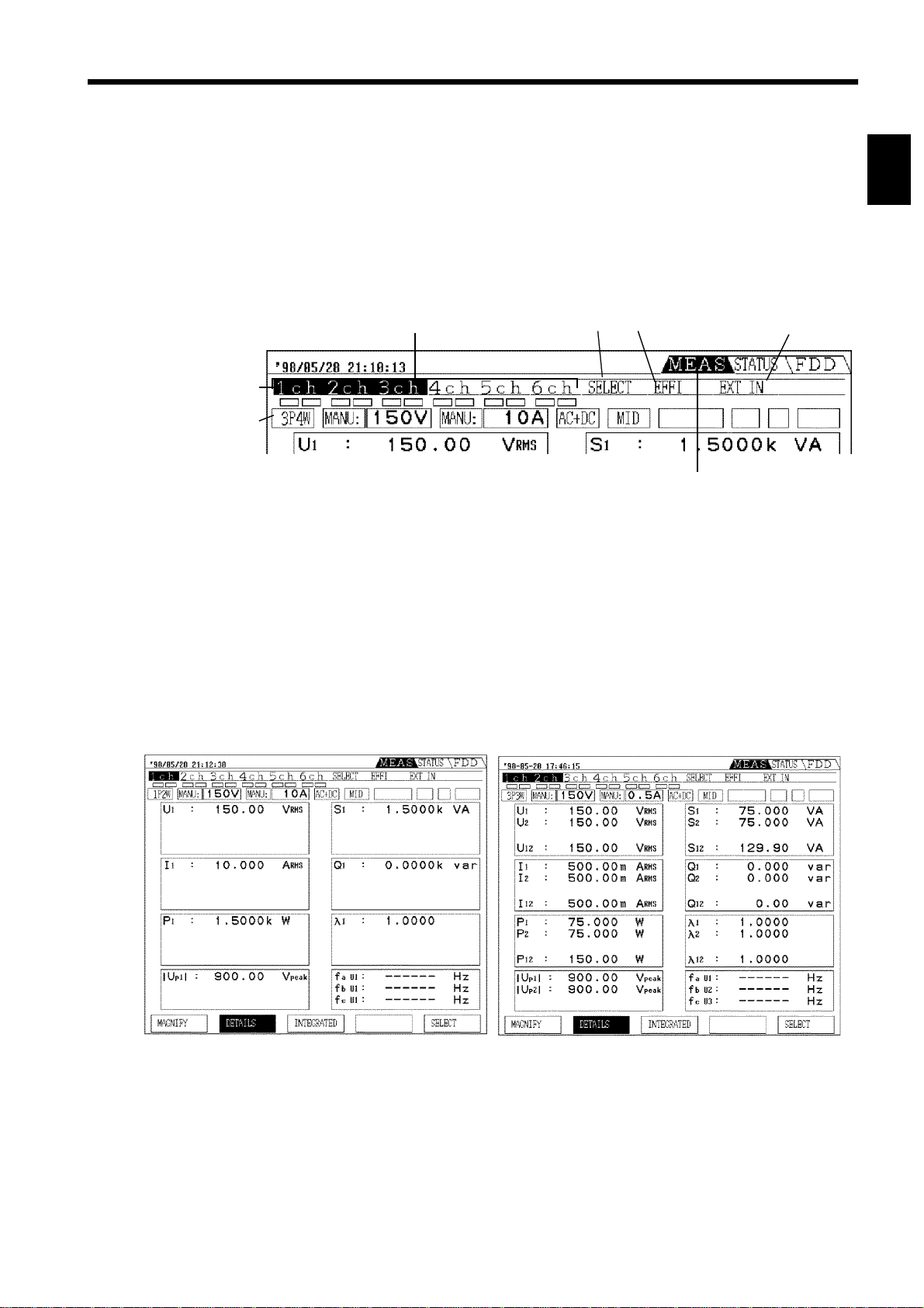
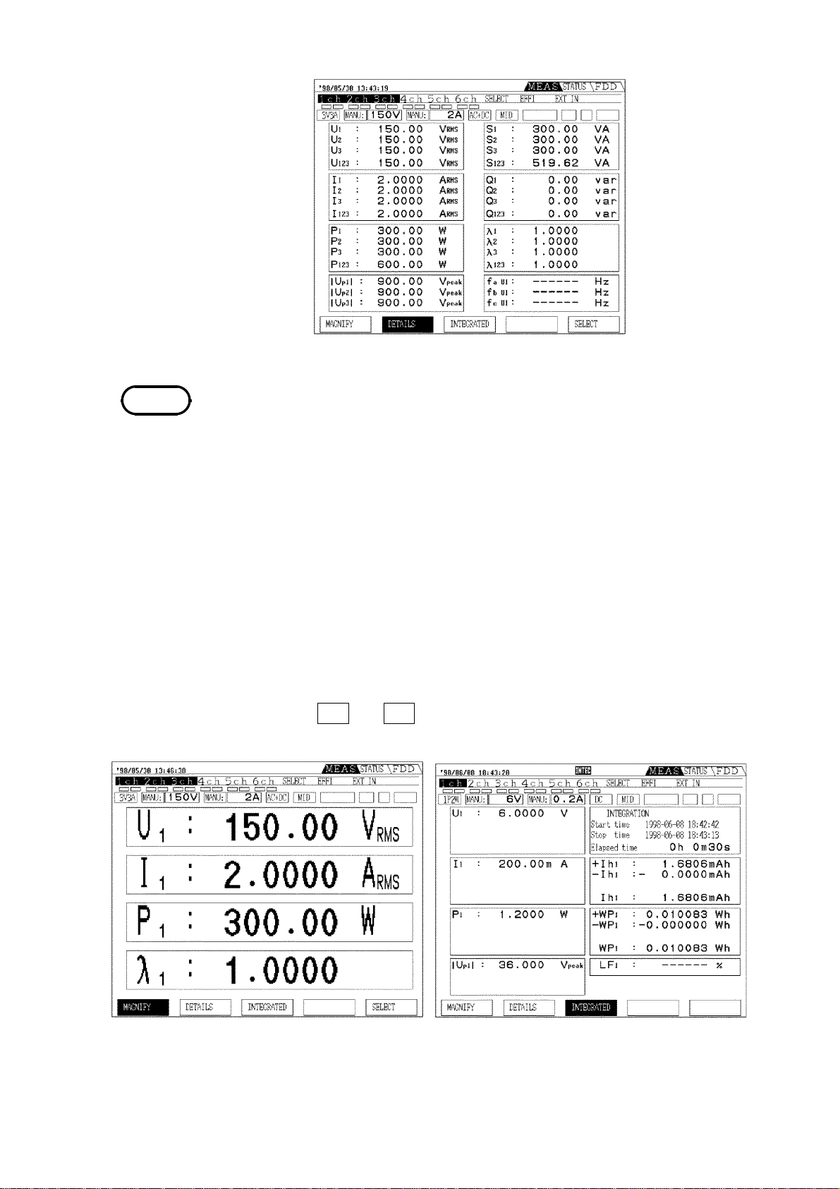
2.2.2 MEAS Screen (Measurement Screen)
This screen displays measurement results. The displays available depend on
the options installed.
Switch from one display to another using the
this case the second row of cursor positions from the top of the screen shows
the currently displayed page. Each item in this row is blank if the
corresponding option is not installed. The third row on the screen shows the
settings for the currently displayed channel.
PAGE
key on the front panel. In
1
2
3
#201.tif
Use the PAGE keys
Use the Function keys
① Screen for each channel (channels 1 to 6) [
①②③④
Measurement Screen
1chto6ch
・This is the screen when the cursor position is on 1ch (channel 1) to 6ch
(channel 6). This corresponds to the installation of the 9600, 9601, and 9602
options.
・For multi-channel combinations, of single-phase three-wire (1P3W) and
above, the measurement values are displayed combined on a single screen. In
this case, the cursor also appears on the corresponding channel numbers
together.
]
4
5
6
7
8
9
10
#202.tif
────────────────────────────────────────────────────
In 1P2W mode
#203.tif
In 1P3W, 3P3W mode
2.2 Names and Configuration of Screen
11
12
13
14
A
Page 28
10
────────────────────────────────────────────────────
3V3A/3P4W mode
#204.tif
NOTE
・ The subscript numbers on symbols indicate channels. For example, "U1"
indicates that the voltage measured on input unit channel 1 is displayed.
The indication "U
" indicates that the SUM value of the voltages measured
123
on input unit channels 1, 2 and 3 is displayed.
・ When the SUM value of the active power in 3V3A mode is shown as, for
example, "P
", then "P1+P2" is calculated, and "P3" is ignored.
123
・ In 1P2W mode, when DC mode is selected, the reactive power (Q), power
factor (λ), phase angle (φ) for each channel are displayed, but they are
meaningless. In 3P3W or 3V3A mode, when three-phase three-wire is
measured, active power (P), apparent power (S), reactive power (Q), power
factor (λ), phase angle (φ) for each channel are displayed, but they are
also meaningless. Make a setting for display to off not to display them.
・ See Section 19.3, "Calculations."
・Other display screens include enlarged and integration value displays;
function keys
F1
and
switch to these displays.
F3
#205.tif
Enlarged display screen
Integration display screen
1 P2W, DC mode
#206.tif
────────────────────────────────────────────────────
2.2 Names and Configuration of Screen
Page 29
11
────────────────────────────────────────────────────
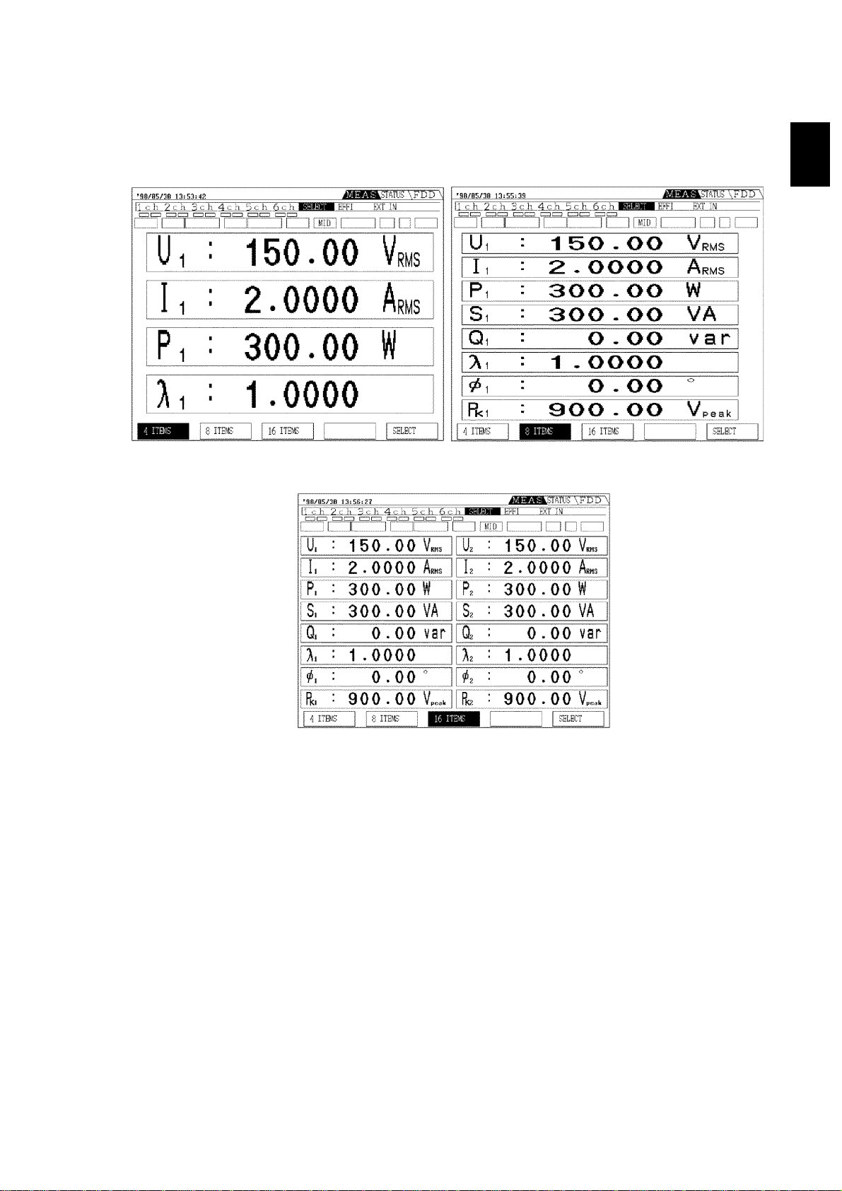
#207.tif
② Selection screen [
・Required items (except harmonics, flicker, and integration values) can be
selected from all of the measurements being made and displayed.
・The screen format can be selected to show 4, 8, or 16 items.
4 items display screen
SELECT
]
8 items display screen
#208.tif
1
2
3
4
5
6
7
#232-9.tif
16 items display screen
8
9
10
11
12
13
14
────────────────────────────────────────────────────
2.2 Names and Configuration of Screen
A
Page 30
12
────────────────────────────────────────────────────
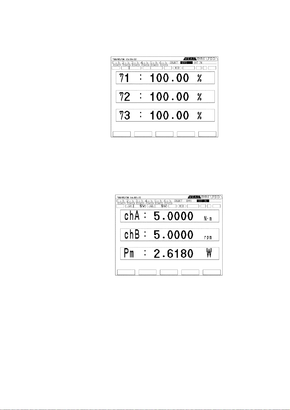
③ Efficiency screen [
By combining measurement values (active power, motor power), this
calculates and displays the efficiency.
#232-10.tif
④ External input screen [
This is displayed when the optional 9603-01 EXTERNAL SIGNAL INPUT
UNIT is installed. The motor power (Pm) is displayed only when the unit
settings for channel A is torque, for channel B is number of rotating (rpm).
EFFI
]
EXT IN
]
#232-11.tif
⑤ Harmonic waveform screen
This is displayed when the optional 9605-01 HARMONIC MEASURMENTS
UNIT is installed. (See the 9605-01 Instruction Manual)
────────────────────────────────────────────────────
2.2 Names and Configuration of Screen
Page 31

13
────────────────────────────────────────────────────
2.2.3 STATUS Screen (Setting Screen)
This screen provides various settings. The screens correspond to the installed
options. Switch from one display to another using the
panel. In this case the second row of cursor positions from the top of the
screen shows the currently displayed page.
From this row, you can also check which options are installed.
①② ③ ④⑤⑥
#233-1.tif
PAGE
STATUS screen
key on the front
① Unit screen [
UNIT
]
・This shows a list of the settings for each channel. In this case too, the
settings are collected together according to the channel combinations
depending on the connection mode.
・Moving the cursor to an item with the
CURSOR
keys allows that item to be
set or changed.
1P2W 6 types
3P4W 2 types
#233-2.tif #233-3.tif
────────────────────────────────────────────────────
2.2 Names and Configuration of Screen
Page 32

14
────────────────────────────────────────────────────
② Time control screen [
TIME
]
This shows the settings for the response, averaging function, the interval
time, timer time, and real-time control time.
#CHANGE
233-4.tif
③ Frequency screen [
This shows the settings for the output to FDD/printer, printing direction,
saving screen color on FD, D/A output, frequency measurement function
source, and frequency range of the unit.
FREQ/OUTPUT
]
#CHANGE
233-5.tif
④ System screen [
This shows the settings for the GP-IB/RS-232C, display color, LCD
backlight, calculation, beep sound, display of input out-of-range, language,
real-time, system reset.
#CHANGE
233-6.tif
SYSTEM
]
────────────────────────────────────────────────────
2.2 Names and Configuration of Screen
Page 33

15
────────────────────────────────────────────────────
⑤ Efficiency screen [
EFFI
]
This sets the items to be substituted in the efficiency calculation expression.
#233-7.tif
(6) External input screen [
This is displayed when the optional 9603-01 EXTERNAL SIGNAL INPUT
UNIT is installed, and some settings are made for the 9603-01.
EXT UNIT
]
#233-8.tif
(7) Harmonic waveform screen
This is displayed when the optional 9605-01 HARMONIC MEASURMENTS
UNIT is installed. (See the 9605-01 Instruction Manual)
────────────────────────────────────────────────────
2.2 Names and Configuration of Screen
Page 34

16
────────────────────────────────────────────────────
2.2.4 FDD Screen
This sup ports file name setting of a floppy disk, and saving and loading of
the unit settings.
#234.tif
────────────────────────────────────────────────────
2.2 Names and Configuration of Screen
Page 35

17
────────────────────────────────────────────────────
2.3 Indicators
The following indicators are shown by panel key operation.
#235.tif
SHIFT
Indicates when the
SHIFT
key is pressed. Pressing again goes
off.
KL
Indicates key lock state (red), and remote state by GP-IB/RS232C (yellow).
HOLD
Indicates the displays are held.
PEAK
Indicates the peak hold function is active.
TOTAL
STIME
Indicates during real time control. A blue display indicates
Indicates total value after time averaging.
standby during real-time control, and a yellow display
indicates within setting time.
INTEG
Indicates integration or operation by time controls.
A yellow display indicates that operation is in progress, and a
blue display indicates during waiting.
FD
Indicates the output method is set to FDD.
PRI
Indicates the output method is set to printer.
A yellow display indicates normal and a red display indicates
there is no paper or printer lever is head-up.
────────────────────────────────────────────────────
2.3 Indicators
Page 36

18
────────────────────────────────────────────────────
2.4 Peak Over Indication
If the input voltage or current waveform peak exceeds six times the range
value, a "PEAK" indication appears.
These indications appear on the screen below the channel number, the
voltage indication on the left and the current indication on the right, so that
even a "PEAK" state can be detected even for channels not currently
displayed.
For example, the following indications mean that the current on channel 4
and the voltage on channel 6 have peak values exceeding six times the range
value.
#236.tif
Indicates when voltage or current
Current on channel 4 has peak
values exceeding six times the
range value
Voltage on channel 6 has peak
values exceeding six times the
range value
for any channels has peak values.
NOTE
These indications are only valid within the range of the maximum input
voltage and current for each input unit.
────────────────────────────────────────────────────
2.4 Peak Over Indication
Page 37

19
────────────────────────────────────────────────────
Chapter 3
Preparation for Measurement
1
2
3
4
5
3.1 Notes on Use
DANGE R
Always connect the powermeter input (including current sensor) to
the secondary side of the breaker. On the secondary side of a
breaker, even if the lines are shorted the breaker can trip and
prevent an accident. On the primary side, however, the current
capacity may be large, and in the event of a short-circuit there
may be a serious accident.
Once the connections are made, do not touch the input terminals,
and the voltage and current transformers. There are exposed live
parts, and a danger of electric shock or serious accident.
Check that the terminals are tightened securely. If the connections
should become detached, there is a danger of a short-circuit or
electric shock accident. Additionally, if the connections are not
properly tightened, the contact resistance increases, which may
lead to the generation of heat, or fire.
The maximum input voltage and current for this unit depend on the
input unit being used. Do not apply an input exceeding the
maximum input voltage and current specified for the input unit.
Exceeding the maximum input voltage or current could damage the
unit or cause a serious accident.
6
7
8
9
10
11
12
────────────────────────────────────────────────────
3.1 Notes on Use
13
14
A
Page 38

20
────────────────────────────────────────────────────
WARNING
In order to prevent accidental electric shock and short circuits, shut
off the power on the line to be measured before connecting DC
voltage or current leads to the terminals.
Be sure to connect the voltage input terminals, current input
terminals correctly. Measurement which is attempted with the wiring
connected incorrectly may cause damage to the unit or a shortcircuit.
The unit is constructed so as to be connected to a ground line via a
three-core power cord that is supplied with the unit. In order to
avoid electric shock, connect the unit to a properly grounded (3-pin)
outlet using the power cord provided.
When using an external voltage transformer, do not leave the
secondary side short-circuited. If a voltage is applied to the primary
while the secondary is short-circuited, a high current will flow
through the secondary, which could lead to fire or malfunction.
When using an external current transformer, do not leave the
secondary side open-circuit. If a current flows through the primary
while the secondary is open-circuit, this can generate a high voltage
on the secondary, which is extremely dangerous.
CAUTION
NOTE
・ To avoid electrical accidents, use wiring with more than adequate
current carrying capacity and voltage insulation properties.
・ When the power is turned off, do not apply voltage or current to the
voltage input terminal, current input terminal, or clamp sensor. Doing
so may damage the unit.
・ For 3P3W, 3V3A measurement, the active power values for each channel are
found from the voltages between lines and the currents on each line, and
have no individual significance.
・ If the maximum values of the voltage or current on the lines being measured
exceed the measurement range of this unit, use an external voltage
transformer (PT) or current transformer (CT). In this case, by setting the
corresponding PT and CT ratios with the scaling function of this unit, you
can directly read off the measured values. See Section 4.5, "Setting the
scaling."
・ For combinations 1P3W and above, there are restrictions on the
combinations of input units. See Section 4.1, "Setting the Wiring Mode."
・ When using an external voltage transformer (PT) or current transformer
(CT), its precision, phase accuracy, frequency characteristics, and so on, may
greatly affect the error in the measured power value. Use transformers with
adequate frequency characteristics and small phase error for the frequency
band of the line being measured.
・ When using a voltage transformer (PT) or current transformer (CT), ground
one side of the secondary for safety.
────────────────────────────────────────────────────
3.1 Notes on Use
Page 39

21
────────────────────────────────────────────────────
Pre-Measurement Inspection
Before using the instrument the first time, verify that it operates normally to
ensure that the no damage occurred during storage or shipping. If you find
any damage, contact your dealer or Hioki representative.
Peripheral Device Inspection
Inspect the voltage measurement cables or connection cables.
Is the insulation of the voltage measurement cables
or connection cables to be used dameged, or is
bare metal exposed?
Inspect the current sensors
Is a sensor cracked or damaged?
Is the insulation of the any cable to be used
dameged, or is bare metal exposed?
No Metal Exposed
No
No Metal Exposed
Inspection complete
Metal Exposed
Yes
Metal Exposed
Do not use if damage
is present, as you
could receive an
electric shock.
Replace the damaged
items.
1
2
3
4
5
6
7
8
9
10
11
12
13
14
────────────────────────────────────────────────────
3.1 Notes on Use
A
Page 40

22
────────────────────────────────────────────────────
3.2 Basic Operating Procedure
Check that the line to be measured is shut off, and
測定対象のラインが遮断されていることを確認、
check that this unit is powered off and the power
および本器の電源が OFF され電源コードを抜いて
cord disconnected from the outlet.
あることを確認する
Connect the power cord to the 3P-outlet.
Turn the power on.
Turn the power on.
Turn the power on.
(Warming-up 1 hour or more
When using the 9600 or 9602,
carry out degaussing after warming-up.)
Make a connections.
See Section 3.4, 3.5.
Check there is no short circuit
Set the connection mode.
Set the display item.
Set the measurement range.
Set the each items.
Check the connection of line being measured again,
and turn on the power line.
Start the measurement.
────────────────────────────────────────────────────
3.2 Basic Operating Procedure
Page 41

23
────────────────────────────────────────────────────
3.3 Powering On
WARNING
Before turning on the power, make sure that the voltage of the power
supply being used matches the supply voltage indicated on the rear
panel of the unit. If an attempt is made to use an improper supply
voltage, there is danger of damage to this unit and of life-threatening
risk to the operator.
1
2
3
CAUTION
The unit is constructed so as to be connected to a ground line via a
three-core power cord that is supplied with the unit. In order to
avoid electric shock, connect the unit to a properly grounded (3-pin)
outlet using the power cord provided.
The power switch has a microgap construction, and it is therefore
essential to use it close to a power outlet. When the unit is not in
use, and while making connections to the circuit being tested, isolate
the unit electrically from the power supply, for example by removing
the power cord plug from the outlet.
・ Should the unit emit smoke, or a strange smell or strange sound,
immediately stop testing operations, power the unit off, and remove the
power cord from the outlet, shut off the circuit being tested,
disconnect the unit, and consult your HIOKI representative. Continued
use of the unit could lead to fire or electric shock accidents.
・ When the power is turned off, do not apply voltage or current to the
voltage input terminal, current input terminal, or clamp sensor. Doing
so may damage the unit.
1. Confirm that the voltage of the power supply being used matches the
supply voltage indicated on the rear panel of the unit.
2. Confirm that the power switch on the front panel is off.
3. Connect the supplied power cord to the AC inlet on the rear pane.
4. Connect the power cord to a grounded three-pin outlet. If no grounded
outlet is available, use the supplied ground adapter.
5. Turn on the power switch on the front panel.
6. The unit starts the self-test. It is completed after about 10 seconds.
4
5
6
7
8
9
10
11
12
Self-Test
In the self test, the following tests are carried out, then after about 10
seconds the measurement screen automatically appears.
・Unit version
・Installed options
・RAM check
NOTE
────────────────────────────────────────────────────
If there is a problem in the settings, this screen remains displayed and the
unit stops. If this happens again after powering off and on, the unit has
developed a fault. Stop measurement, and shut off the line being measured,
then power off the unit. Disconnect the test wiring and the power cord.
Contact your
HIOKI
service representative for repair.
3.3 Powering On
13
14
A
Page 42

24
────────────────────────────────────────────────────
3.4 Connecting the Direct Input Unit
The following diagrams show the connections in various modes when using
the 9600
AC/DC DIRECT INPUT UNIT
and 9601
■ Single-phase two wires (1P2W) i: 1 to 6
Source
Load
Source
Load
AC DIRECT INPUT UNIT
Source
.
Load
CT
U
±
I
±
Channel (i)
transformers (PT, CT)
U
±
I
±
Channel (i)
Connecting the measured
line directly to the unit
CT
U
±
I
±
Channel (i)
Using the current
transformer (CT)
Using the voltage and current
■ Single-phase three wires (1P3W) i: 1, 3, 4, 5
Source
N
±
±
Load
U
I
U
±
I
±
Source Load
N
N
CT
U
±
I
±
CT
±
±
Source Load
N
N
CT
U
I
PT
U
±
I
±
CT PT
U
±
±
N
I
Channel (i+1)
Connecting the measured
line directly to the unit
────────────────────────────────────────────────────
3.4 Connecting the Direct Input Unit
Channel (i)
Channel (i+1)
Using the current
transformer (CT)
Channel (i)
Channel (i+1)
Channel (i)
Using the voltage and current
transformers (PT, CT)
Page 43

25
────────────────────────────────────────────────────
■ Three-phase three wires (3P3W)
Source
R
S
T
U
±
I
±
Channel (i+1)
Channel (i)
U
±
I
±
Load
Source
R
R
S
S
T
T
Connecting the measured
line directly to the unit
■ Three-phase three wires (3V3A)
Source
R
S
T
Load
Source
R
R
S
S
T
T
CT
U
±
I
±
Channel (i+1)
Using the current
transformer (CT)
CT
Channel (i)
±
±
U
I
Load
Load
Source
R
R
S
S
T
T
CT
PT
U
±
I
±
Channel (i+1)
CT PT
Channel (i)
Using the voltage and current
transformers (PT, CT)
Source
R
R
S
S
T
T
i: 1, 3, 4, 5
Load
R
S
T
U
±
I
±
i: 1, 4
Load
R
S
T
1
2
3
4
5
6
U
±
I
±
Channel
(i+2)
U
±
I
±
Channel
(i+1)
U
±
I
±
Channel
(i)
Connecting the measured
line directly to the unit
■ Three-phase four wires (3P4W)
Source
R
S
T
N
U
±
I
±
Channel
(i+2)
U
±
I
±
Channel
(i+1)
±
±
Channel
Load
U
I
(i)
Source
R
R
S
S
T
T
N
N
Connecting the measured
line directly to the unit
CT
±
±
Channel
(i+2)
CT
U
I
Channel
Using the current
transformer (CT)
CT
±
±
Channel
(i+2)
U
I
CT CT
Channel
Using the current
transformer (CT)
U
±
I
±
(i+1)
U
±
I
±
(i+1)
CT
Channel
Channel
U
±
I
±
(i)
Load
U
±
I
±
(i)
PT
CT CT
U
±
I
±
Channel
(i+2)
PT
U
±
I
±
Channel
(i+1)
CT
Using the voltage and current
transformers (PT, CT)
Source
R
R
S
S
T
T
N
N
PT PT
CT
±
±
Channel
(i+2)
U
I
CT CT
U
±
I
±
Channel
(i+1)
Using the voltage and current
transformers (PT, CT)
PT
U
±
I
±
Channel
(i)
i: 1, 4
Load
PT
U
±
I
±
Channel
(i)
7
8
9
10
R
S
11
T
N
12
13
14
────────────────────────────────────────────────────
3.4 Connecting the Direct Input Unit
A
Page 44

26
────────────────────────────────────────────────────
3.5 Connecting the Clamp Input Unit
The following diagrams show the connections in various modes when using
the 9602
AC/DC CLAMP INPUT UNIT
.
Single-phase two wires (1P2W)
Source Load
U
±
SENSOR
I
Channel (i)
i: 1 to 6
Three-phase three wires (3P3W)
Source
R
S
T
Single-phase three wires (1P3W)
Source Load
N
U
±
SENSOR
I
Channel (i+1)
U
±
SENSOR
I
Channel (i)
Three-phase three wires (3V3A)
Source
Load
R
R
S
S
T
T
N
i: 1, 3, 4, 5
Load
R
S
T
U
±
SENSOR
I
Channel (i+1)
U
±
SENSOR
I
Channel (i)
i: 1, 3, 4, 5
Three-phase four wires (3P4W)
Source
R
S
T
N
U
±
SENSOR
I
Channel (i+2)
U
±
SENSOR
I
Channel (i+1)
U
±
SENSOR
I
Channel (i)
Load
i: 1, 4
U
±
SENSOR
I
Channel (i+2)
R
S
T
N
U
±
SENSOR
I
Channel (i+1)
U
±
SENSOR
I
Channel (i)
i: 1, 4
────────────────────────────────────────────────────
3.5 Connecting the Clamp Input Unit
Page 45

27
────────────────────────────────────────────────────
3.6 Measurement Losses
This unit is designed to have low measurement losses, and an extremely
small effect on the power measurement values, but the following variant
connection methods may be used to further reduce the effect of measurement
losses.
(1) When the voltage input is connected to the power supply side, the
measurement includes losses from the input resistance of the current input
terminals, but this yields the minimum measurement losses when the
measured voltage is high and the measured current is low.
Source
U
±
±
Load
Source Load
I
R
Input resistance on
the current side
U
±
I
Input resistance
on the voltage side
±
r
(2) When the current input is connected to the power supply side, the
measurement includes losses from the input resistance of the voltage input
terminals, but this yields the minimum measurement losses when the
measured voltage and measured current is low.
Source
U
±
I
±
Load
Input resistance on
the current side
I
Source Load
Input resistance on
±
r
the voltage side
U
R
±
NOTE
When using a clamp-on input unit as the current sensor, the measurement
losses of the current sensor can be ignored, so method (1) above should be
used.
────────────────────────────────────────────────────
3.6 Measurement Losses
Page 46

28
────────────────────────────────────────────────────
3.7 Error Messages
"Integration in progress (press START/STOP key to stop)."
"Integration on standby (press SHIFT + START keys to reset)."
"Reset not possible while integration in progress."
"Time averaging is on."
Operation
Floppy
"Stop time has passed, so real-time control is turned off."
"Output in progress."
"Hold function operating."
"Peak hold function operating."
"Program load failed."
"Disk access error"
"File cannot be opened"
"Save failed"
"Load failed"
"Formatting failed"
"File names may not include spaces."
"Disk is write-protected"
"Disk full"
Printer
"Printer: head temperature error."
"Printer: motor drive voltage error."
"Printer: head is up."
"Printer: no paper."
────────────────────────────────────────────────────
3.7 Error Messages
Page 47

29
────────────────────────────────────────────────────
3.8 System Reset
To reset settings to the initial factory settings, there are following two
methods.
・Whenpoweringoff
Turn the power on pressing the
・ On the STATUS screen
1. Press the
2. Using the
press the
3. Pressing
STATUS
CURSOR
RESET
(
F5
YES
(
F1
key to display the
keys, move the cursor to "SYSTEM RESET", and
)key.
) carries out system reset.
All settings are reset to the following their initial factory settings.
SHIFT
key until beep sounds.
SYSTEM
screen.
Connection mode 1P2W (all channels)
Coupling mode
Voltage range
Current range
PT/CT/SC ratios
LPF
phF
Peak
Response MID
Average OFF, averaging t ime: 8
Interval time
Timer
Real time control
Output type
Output item ON (all items)
Direction of printing Forward
Screen save color Monochrome
D/A output
Frequency
measurement
Frequency range
Interface GP-IB, address: 1
AC (all channels)
AUTO, RMS (all channels)
AUTO, RMS (all channels)
OFF (all channels) initial
value: 1
OFF (all channels)
OFF (all channels)
U (all channels)
OFF, initial value: 0h1m00s
OFF, initial value: 0h1m00s
OFF
OFF
all U1
all U1forfa, fb, fc
all AUTO
Display color Normal
Backlight
Calculation
expression (S,Q)
Beep sound ON
Out of range input
Language
Real time
Zero suppress
function (Integration)
Efficiency screen on
STATUS
External input
screen on STATUS
Magnification display
for channel 1 to 6
on MEAS
Details display for
channel 1 to 6 on
MEAS
4 items display on
MEAS
8 items display on
MEAS
16 items display on
MEAS
OFF
TYPE1
OFF
JAPANESE
Current time
0.5%
P1 both denominator and
numerator for
Channels A and B: 10 V
range, scaling: 1, unit:V
U / I / P /
U / I / P /|Up|/S / Q /
U1/I1/P1/λ1
U1/I1/P1/S1/Q1/λ1/φ1/Pk1
U1/I1/P1/S1/Q1/λ1/φ1/Pk1
both left and right
η1,η2,η
λ
3
λ
────────────────────────────────────────────────────
3.8 System Reset
Page 48

30
t
────────────────────────────────────────────────────
3.9 Operations During Power Failure
CAUTION
・ In the DC and AC+DC modes, after the power is restored, an offset
due to the circuit design may be output. In some cases the data may
be invalid.
・ When the unit is powered off as a result of a power failure, continuing
to input voltage and current may damage the unit.
Screen display The screen display goes blank, and after power restoring redisplays the
screen. However, the
STATUSorFDD
screen is displayed before power failure,
the MEAS screen for channel 1 is redisplayed.
Measuremen
data
If the display data was being held when power was lost, all of the data that
was being held is not retained.
Integration data ・ Manual integration
A power failure is treated as a zero input and zero elapsed time; after the
power is restored integration restarts.
・ Timer integration
A power failure is treated as a zero input and zero elapsed time; after the
power is restored integration restarts, and stops when the timer time has
elapsed.
・ Real-time control integration
If the power failure starts and ends while the unit remains on standby, there
is no effect.
If a power failure starts while the unit is on standby, and ends after the set
start time, integration starts from the time when the power is restored. In this
case the interval from the set start time until the power is restored is treated
as a zero input. The elapsed time is shorter than time from start to stop.
A power failure during integration operation is treated in the same way as
for timer integration.
────────────────────────────────────────────────────
3.9 Operations During Power Failure
Page 49

31
────────────────────────────────────────────────────
Floppy disk drive ・ When automatic output is selected
After the power is restored, a character string indicating that there was a
power failure is output. (time of power failure and restoring)
・ Power failure during saving
The data being saved is invalid. In the worst case there is a possibility of the
file itself being corrupted.
・ Power failure during loading
The setting is invalid. The system reset should be carried out. Turn on the
power pressing the
SHIFT
key.
Printer ・ During manual printing
After power is restored, the printing is not started. Restart the printing.
・ During automatic output and before stop time the power is restored
After power is restored, the time when the power failure occurs and the
power is restored are printed and then printing is restarted.
・ During automatic output and after stop time the power is restored
After power is restored, the time when the power failure occurs and the
power is restored are printed and then operation stops.
────────────────────────────────────────────────────
3.9 Operations During Power Failure
Page 50

32
────────────────────────────────────────────────────
────────────────────────────────────────────────────
3.9 Operations During Power Failure
Page 51

33
────────────────────────────────────────────────────
Chapter 4
1
2
Setting and Using the Basic
Functions
4.1 Setting the Wiring Mode (1P2W to 3P4W)
This unit can have up to six input unit channels, allowing a single unit to
measure anything from six 1P2W lines to two 3P4W systems. The
connection mode of each channel also appears on the screen as shown
below.
41-1.tif
Wiring mode
1P2W
1P3W
3P3W
3V3A
3P4W
3
4
5
6
7
8
9
Set the line to be measured under "
channel combinations set here determine the screen configuration.
UNIT
" on the STATUS screen. The
10
11
12
13
14
A
────────────────────────────────────────────────────
4.1 Setting the Wiring Mode (1P2W to 3P4W)
Page 52

34
────────────────────────────────────────────────────
UNIT
WIRING
UNIT Page
1. Press the
STATUS
keys to display the "
2. Using the
WIRING
"
3. Press
CURSOR
" item.
(
F5
SELECT
key, then use the
UNIT
"page.
keys, move the cursor to the
) to switch to the connection
PAGE
( )
setting screen.
4. In the Wiring screen, a list of the installed input
units appears.
Move the cursor to the desired combination to be
selected.
Wiring Screen
UNIT Page
##41-2.tif
-3
-4
5. Press
F1
SET
(
) to confirm. This automatically
returns to the previous screen.
6. When a number of channels are combined, move
the cursor to the wiring item.
When using two channels, select from
F2
3V3A
(
3P3W
(
), and for three channels select from
)and
MEAS
key to return to the measurement
F2
3P4W
(
).
and
F1
7. Press the
F1
1P3W
(
screen, where measurement is now possible.
NOTE
On the Wiring screen, if the combination is not
changed and then
may be initialized. Pressing the
is pressed, the setting items
F1
PAGE
key to exit
from the screen does not initialize the items.
)
────────────────────────────────────────────────────
4.1 Setting the Wiring Mode (1P2W to 3P4W)
Page 53

35
────────────────────────────────────────────────────
NOTE
Measurement line Mode Display item
Single-phase two-wire
(1φ2W)
・ It is only possible to select from the combinations shown in the connection
setting screen.
For combinations 1P3W and above, adjacent units must be of the same type.
Channels
1 2 3 4 5 6
① 1P2W 1P2W 1P2W 1P2W 1P2W 1P2W
② 1P3W / 3P3W 1P2W 1P2W 1P2W 1P2W
③ 1P3W / 3P3W 1P3W / 3P3W 1P2W 1P2W
④ 1P3W / 3P3W 1P3W / 3P3W 1P3W / 3P3W
⑤ 3V3A / 3P4W 1P2W 1P2W 1P2W
⑥ 3V3A / 3P4W 1P3W / 3P3W 1P2W
⑦ 3V3A / 3P4W 3V3A / 3P4W
・ When using the 9602
the same sensor type can be selected. In other cases, all are set to 1P2W.
・ When using the 9602 AC/DC CLAMP INPU T UNIT, if the sensor
configuration is changed (including with the sensor not connected), and the
unit is then powered on, "Resetting due to configuration change." is
displayed. Pressing
reset and settings remain unchanged, but the display value for current may
be changed. Return the configuration settings and power on again. The
message is not displayed.
・ When using clamp-on units, if the sensor rating is changed and the unit is
then powered on, in the 1P2W mode the CT ratio within the unit is
automatically set accordingly. For combinations 1P3W and above, if other
channels in the combination have different ratings the combination is
disabled for measurement.
・ The display items in the various modes are as follows.
1P2W U, I, P, Q, S, λ/φ, |Up|/|Ip|
AC/DC CLAMP INPUT UNIT
(YES)
F1
resets settings. Pressing
, only a combination of
(NO)
F2
does not
1
2
3
4
5
6
7
8
9
10
Single-phase three-wire
(1φ3W)
Three-phase three-wire
(3φ3W)
Three-phase four-wire
(3φ4W)
────────────────────────────────────────────────────
1P3W
(channels 1+2)
3P3W
(2 voltages, 2 currents,
2 power meters method)
(channels 1+2)
3V3A
(3 voltages, 3 currents,
2 power meters method)
(channels 1+2+3)
3P4W
(channels 1+2+3)
・ Although the display will show for each channel 3P3W or 3V3A the active
power (P1, P2 and P3), reactive power (Q1, Q2 and Q3), apparent power
(S1, S2 and S3), power factor (
and
φ
3), please be aware that these figures have no meaning.
・ Power factor (λ) and phase angle (φ) are not be displayed simultaneously.
・ The measurement values for three-phase three-wire in 3P3W and 3V3A mode
are same because of same measurement method.
U1, U2, U12, I1, I2, I12, P1, P2, P12, Q1, Q2, Q12, S1, S2,
S12, λ1/φ1, λ2/φ2, λ12/φ12, |U1p|/|I1p|, |U2p|/|I2p|
U1, U2, U12, I1, I2, I12, P12, Q12, S12, λ12/φ12,
|U1p|/|I1p|, |U2p|/|I2p|
U1, U2, U3, U123, I1, I2, I3, I123, P123, Q123, S123,
λ123/φ123, |U1p|/|I1p|, |U2p|/|I2p|, |U3p|/|I3p|
U1, U2, U3, U123, I1, I2, I3, I123, P1, P2, P3, P123, Q1, Q2,
Q3, Q123, S1, S2, S3, S123, λ1/φ1, λ2/φ2, λ3/φ3,
λ123/φ123, |U1p|/|I1p|, |U2p|/|I2p|, |U3p|/|I3p|
λ1,λ
2 and
4.1 Setting the Wiring Mode (1P2W to 3P4W)
λ
3), and phase angle (
φ1,φ
2
11
12
13
14
A
Page 54

36
────────────────────────────────────────────────────
4.2 Setting the Coupling Mode (DC/AC+DC/AC)
UNIT
SHIFT
COUPLING
Coupling mode
DC
AC+DC
AC
42-1.tif
##42-2.tif -3
The coupling mode can be selected according to the measurement being
performed.
Switching using the panel keys
CURSOR
DC → AC+DC → AC
1. Switch to display the channel for which you wish
to change the setting.
2. Press the
SHIFT
key, then use the
CURSOR
change.
Pressing the
CURSOR
key switches connection
mode.
Switching on the STATUS screen
1. Press the
STATUS
keys to display the "
2. Select mode from
key, then use the
UNIT
"page.
to
F1
F3
PAGE
( )
.
key to
F1 F2 F3
NOTE
・ The voltage and current for a single channel and for combinations of 1P3W
and above are forced to the same settings. In this case the setting for the
lowest-numbered channel is used.
・ When DC mode is selected, the polarity is displayed for the voltage and
current.
・ In DC mode, reactive power (Q), power factor (λ), and phase angle (φ) are
displayed but they are meaningless.
・ For DC mode, the active power (P) is displayed as a calculated AC+DC
value. For this reason, if there is a superimposed AC waveform the value
may not agree with the U×I calculation.
・ When AC+DC or AC mode is selected, the display values of voltage and
current are always positive values.
・ When using the 9601 AC DIRECT INPUT UNIT or AC sensor for the 9602
AC/DC CLAMP INPUT UNIT, DC or AC+DC mode cannot be selected.
────────────────────────────────────────────────────
4.2 Setting the Coupling Mode (DC/AC+DC/AC)
Page 55

37
────────────────────────────────────────────────────
4.3 Switching the Voltage Range and Current Range
1
When the voltage range and current range is displayed on the screen for each
channel, it is also possible to change the ranges directly with the panel keys.
This is also possible from the STATUS screen in the "
43-1.tif
Voltage range
43-2.tif
-
Effective input range
The effective input range is 5% to 110% of range.
(for the 9600 and 9601, 5% to 100% for 1 kV range only, for the 9602, 5%
to 100% for 600 V range only)
Display range
The value which can be displayed is up to 130% of range. If the value
exceeds this range, "o.r" is displayed.
UNIT
" display.
Current range
2
3
4
5
6
7
8
9
10
11
12
13
14
A
────────────────────────────────────────────────────
4.3 Switching the Voltage Range and Current Range
Page 56

38
────────────────────────────────────────────────────
Switching the range on each channel screen.
RANGE
1. Switch to display the channel for which you wish
to change the setting.
U
I
2. Hold down the panel
RANGE
(+,-) key until the
desired setting range is displayed.
6V⇔ 15 V ⇔ 30 V ⇔
60 V ⇔ 150 V ⇔ 300 V ⇔
600 V ⇔ 1kV
UNIT
URANGE
F1 F2 F5
NOTE
・ For channel combinations of 1P3W and above, the channels are forced to the
same range. In this case the range for the lowest-numbered channel is used
for all of the channels.
・ The auto ranging function switches up a range when a measurement value
exceeds 110% of measurement range (out-of-range) or when a waveform
peak exceeds six times the range value (peak over), and switches down a
range when the value is less than 30% of the nominal range. When
measuring a distorted waveform the range selection may not be stable. In
this case use manual range setting.
・ When the integration function time average has started, auto ranging is
disabled, and the range remains fixed from that point.
3. To set auto ranging, hold down the panel
RANGE
(+) key or press both (+,-) keys simultaneously.
4. To cancel auto ranging, press either of the+and
keys.
Switching on the STATUS screen
1. Press the
keys to display the "
2. Using the
STATUS
CURSOR
key, then use the
UNIT
keys, move the cursor to the
channel to be changed of the "
RANGE
3. Select range from
4. Press the
" item.
(↓; range down).
F2
MEAS
(AUTO)
F5
key to return to the measurement
"page.
U RANGE
,
F1
PAGE
( )
I
"or"
(↑; range up),
screen.
-
────────────────────────────────────────────────────
4.3 Switching the Voltage Range and Current Range
Page 57

39
────────────────────────────────────────────────────
4.4 Effective Value (RMS) or Mean Rectified Value
1
(MEAN) Selection
For voltage and current measurement, this unit has two different rectification
circuits, which can be selected according to the signal being measured.
SHIFT
44-2.tif
UNIT
RMS/MEAN
RANGE
U
44-1.tif
I
Switching for each channels on MEAS screen
・To switch the voltage, press the
then press the+key on the U side.
・To switch the current, press the
then press the+key on the I side.
Switching on the STATUS screen
1. Press the
keys to display the "
2. Using the
channel to be changed of the "U"or"I" item.
3. Select
4. Press the
screen.
STATUS
CURSOR
F1
MEAS
(RMS)
key, then use the
"page.
UNIT
keys, move the cursor to the
or
F2
(MEAN)
key to return to the measurement
SHIFT
SHIFT
key, and
key, and
PAGE
.
2
3
4
5
6
( )
7
8
F1 F2
NOTE
・ Display of "RMS" or "MEAN" following the unit RMS and MEAN values
are distinguished by displaying "RMS" or "MEAN" following the unit, as
appropirate. However, these labels do not appear in the DC mode.
・ The formulas for RMS and MEAN calculation depend on the option.
・ For channel combinations of 1P3W and above, the channels are forced to the
same rectification method, but distinct settings can be made for voltage and
current.
・ The RMS and MEAN values agree when the input is a perfect sine wave,
but do not agree for a distorted waveform.
・ Whichever of RMS and MEAN is selected, this has no effect on the active
power (P), but does affect the internally derived apparent power (S), reactive
power (Q), power factor (λ), and phase angle (φ).
・ In DC mode the RMS/MEAN selection is not available.
9
10
11
12
13
14
A
────────────────────────────────────────────────────
4.4 Effective Value (RMS) or Mean Rectified Value (MEAN) Selection
Page 58

40
────────────────────────────────────────────────────
4.5 Setting the Scaling (PT/CT/SC Ratios)
This is used for setting the ratio (PT ratio or CT ratio) when using an
external voltage transformer (PT) or current transformer (CT), and the
scaling factor (SC ratio) for conversion of the active power to other physical
units. When a PT ratio, CT ratio, or SC ratio is set for a particular channel,
on the measurement screen this appears as "SC". The ranges which can be
set are as shown below.
Scaling operation
PT
CT
SC
46-1.tif
Scaling constant
PT ratio (Kp)
CT ratio (Kc)
SC (
Ksc
)
UNIT
Display Setting range
PT 0.0001 to 10000.
CT 0.0001 to 10000.
SC 0.0001 to 10000.
PT
Function Equation
Voltage
Current
Active power
Apparent power
Reactive power
Integrated current
Integrated voltage
1. Press the
STATUS
keys to display the "
2. Using the
CURSOR
U
I
P
S
Q
Ih
WP
key, then use the
UNIT
"page.
keys, move the cursor to the
U×Kp
I×Kc
P×Kp×Kc×Ksc
S×Kp×Kc×Ksc
Q×Kp×Kc×Ksc
Ih×Kc
WP×Kp×Kc×Ksc
PAGE
desired channel of the PT, CT or SC item.
3. Set the numerical value 0 to 9 by using
up),
by using
use the
(↓; down), and move the decimal point
F2
F3
CURSOR
(←.),
keys.
(.→). To move the digit,
F4
( )
F1
(↑;
4. Press the
MEAS
key to return to the measurement
screen.
46-2.tif
F1 F2 F3 F4 F5
────────────────────────────────────────────────────
4.5 Setting the Scaling (PT/CT/SC Ratios)
Page 59

41
────────────────────────────────────────────────────
NOTE
・ For channel combinations of 1P3W and above, the PT ratio, CT ratio, or SC
ratio must be the same for all channels in the combination.
・ When the channel identifies a CT6862, CT ratio of the channel is set to 2.5,
as default. In this state, the current ranges are configured and the measured
values can be read off directly.
Display ranges:「1.25(A) / 2.5A / 5A / 12.5(A) / 25A / 50A」
The default CT ratio is changeable. If you want to change this, please set
the value calculated by the formula: (your desired CT ratio x 2.5). For
example, when you want to set 40 as CT ratio, please set 100(=40 x 2.5).
When CT ratio other than 2.5 (including OFF) is being set, the current
ranges to be displayed are below.
Display ranges:「0.5A / 1A / 2A / 5A / 10A / 20A」
The actual current range configuration with the CT ratio other than 2.5 can
be calculated by multiplying the set CT ratio by each of 0.5A, 1A, 2A, 5A,
10A, 20A.
・ When a CT6865 is used, please set it to CT ratio 2.
The display ranges are [10A/20A/50A/100A/200A/500A], but the range
structure is actually configured to be double the CT ratio after internal
computation.
────────────────────────────────────────────────────
4.5 Setting the Scaling (PT/CT/SC Ratios)
Page 60

42
────────────────────────────────────────────────────
4.6 Setting the Low-pass Filter (LPF)
The input units of the 3194 are provided with a low-pass filter function for
restricting the frequency characteristics.
By using an appropriate filter selection it is possible to eliminate harmonics.
Low-pass filter operation
47-1.tif
CHANGE
UNIT
NOTE
Depending on using the input units, the low-pass filter (LPF) may not be
selected. The frequency range of accuracy assured varies. For details, see
the specifications of the input units.
CURSOR
SHIFT
OFF → 500 Hz→ 5 kHz → 300 kHz
LPF
Switching using the panel keys
1. Switch to display the channel for which you wish
to change the setting.
2. Press the
SHIFT
key, then use the
CURSOR
key to
change.
Pressing the
CURSOR
key switches low-pass
filter.
Switching on the STATUS screen
1. Press the
keys to display the "
2. Using the
channel to be changed of "
STATUS
CURSOR
key, then use the
UNIT
"page.
keys, move the cursor to the
LPF
3. Select desired low-pass filter from
500 Hz
(
),
F3
5 kHz
(
F4
300 kHz
(
),
" item.
).
PAGE
F1
( )
(OFF)
,
F2
4. Press the
MEAS
key to return to the measurement
screen.
F1 F2 F3 F4
47-3.tif
47-2.tif
────────────────────────────────────────────────────
4.6 Setting the Low-pass Filter (LPF)
Page 61

43
────────────────────────────────────────────────────
4.7 Setting the Phase Polarity Discrimination Filter
For distorted waveforms such as inverter waveforms, the reactive power (Q),
power factor (λ), and phase angle (φ) phase angle polarity may not be
stable. In this case, by setting the phase polarity discrimination filter to
"ON" stable polarity measurements can be taken.
Phase polarity discrimination
48-1.tif
filter operation
UNIT
F1 F2
NOTE
phF
1. Press the
STATUS
key, then use the
keys to display the "
2. Using the
CURSOR
keys, move the cursor to the
channel to be changed of "
3. Select
4. Press the
F1
(OFF)
MEAS
or
key to return to the measurement
UNIT
F2
"page.
phF
(ON).
PAGE
" item.
screen.
48-2.tif
・ This is valid when the calculation formula for reactive power (Q)and
apparent power (S) is set to "
TYPE2
"
"or"
TYPE3
" the ON/OFF setting of phF has no effect.
・ This has no effect on voltage (U), current (I), active power (P), or apparent
power (S).
・ For channel combinations of 1P3W and above, the channels are forced to the
same setting.
・ The filter cut-off frequency is 200 Hz, and therefore depending on the
frequency components of distorted waveforms, in some cases stabilization
may not be possible.
・ When the frequency of measurement waveform is 200 Hz or above, set to
OFF.
・ When using averaging function, the polarity is not displayed.
・ When the input signal level is 50% or less of the range, the polarity may not
be discriminated appropriately.
TYPE1
." When the calculation formula is set to
( )
────────────────────────────────────────────────────
4.7 Setting the Phase Polarity Discrimination Filter
Page 62

44
────────────────────────────────────────────────────
4.8 Switching the Waveform Peak Value
The waveform peak value measurement can be set to voltage waveform
(|Up(i)|) or current waveform (|Ip(i)|)
UNIT
F1 F2
NOTE
1. Press the
keys to display the "
2. Using the
STATUS
CURSOR
key, then use the
UNIT
keys, move the "
the desired input unit and press
"page.
PAGE
Peak
F1
" item of
(I)or
(U).
Peak
420-1.tif
・ For any one input unit, it is not possible to measure the voltage peak value
and current peak value simultaneously.
・ The peak value is given as an absolute value, and it is not possible to
determine the sign.
・ The averaging function has no effect on peak value measurement.
・ When measuring a waveform with a superimposed DC component in AC
mode, the peak value of the AC waveform is found after the DC component
has been eliminated.
・ When a low-pass filter is activated, the peak value is found after the
waveform has passed through the filter.
・ For the operation principle of peak value measurement and specifications,
see specifications of input units.
( )
F2
────────────────────────────────────────────────────
4.8 Switching the Waveform Peak Value
Page 63

45
────────────────────────────────────────────────────
4.9 Setting the Response (FAST/MID/SLOW)
There are three settings for the response time of analog outputs from this
unit: FAST, MID, and SLOW.
For measurement of a normal commercial power supply, the FAST setting is
adequate, but is the frequency is low or there are sudden fluctuations, setting
the response to MID or SLOW makes the display more stable.
49-1.tif
Response display
FAST
MID
SLOW
Switching using the panel keys
SHIFT
TIME
RESPONSE
F1 F2 F3
CURSOR
1. Switch to display the channel for which you wish
to change the setting.
2. Press the
SHIFT
key, then use the
CURSOR
▲ key to
change.
Pressing the
CURSOR
▲ key switches response
mode.
Switching on the STATUS screen
1. Press the
STATUS
keys to display the "
2. Using the
RESPONSE
"
3. Select
4. Press the
CURSOR
" item.
F1
MEAS
(FAST)
key, then use the
TIME
"page.
keys, move the cursor to the
F2
(MID)
,
key to return to the measurement
PAGE
( )
F3
(SLOW)
.
,
screen.
49-2.tif
CHANGE
NOTE
・ The response setting applies to all channels together. It is not possible to
make separate settings for each channel.
・ The display refresh rate does not depend on the response setting.
・ The response setting does not affect a channel for which the DC mode is
selected.
・ If the display is unstable even with the SLOW setting, use the averaging
function as well.
────────────────────────────────────────────────────
4.9 Setting the Response (FAST/MID/SLOW)
Page 64

46
────────────────────────────────────────────────────
4.10 Setting the Averaging
(Time averaging/Moving averaging/Exponential averaging)
This unit provides three averaging functions. The time average outputs the
average over a fixed time interval, and the moving average and exponential
average provide values which reflect the previous values.
Averaging display
NOTE
AV-T
AV-M
AV-E
Time averaging
Moving averaging
Exponential averaging
・ This setting applies to all channels together. It is not possible to make
separate settings for each channel.
・ This function does not affect the harmonic analysis/flicker function.
・ The D/A outputs give the values obtained by averaging.
・ Waveform peak measurement values are not averaged.
・ If [TYPE1] is selected as the calculation tpe while using averaging (time
averaging, moving averaging, or indexed averaging), the "si" and "su"
polarities for each channel are calculated as +1.
・ Calculation is performed 16 times per second.
(1) Setting the Time Average (AV-T)
The time average function sequentially sums the data values obtained during
the time interval (interval control time, timer control time, or real-time
control time), and divides by the number of samples. This can be used, for
example, while integrating at particular intervals, to output the average of
some other measurement value during those intervals.
ΣZn
Display value =
Nn
────────────────────────────────────────────────────
4.10 Setting the Averaging
―――
Zn: nth measured data
Nn: number of storing during setting time
Page 65

47
────────────────────────────────────────────────────
TIME
AVE TIME
F1 F2 F3 F4
10-3.TIF #CHANGE
NOTE
・ The time average requires a setting of an interval control time, timer control
time, or real-time control time.
・ Operation with the START/STOP key also affects integration. Therefore,
after completion of averaging or following forced termination, press the
SHIFT key, then press the START/STOP key to reset integration.
・ When used in conjunction with a timer control time or real-time control
time, when the set time elapses the overall average value is displayed and
held, which the unit stops. When this hold state is ended, the unit returns to
normal measurement.
・ For the time average function, floppy disk and printer settings are also
synchronized in the same way.
・ During the time average function operation, it is not possible to change
settings.
・ If an interval control time is set and the
updated each time the interval elapses.
・ During the averaging operation, if an out-of-range data value is included, the
unit indication is red.
・ No polarity is shown for time averaging when [TYPE1] is selected as the
calculation type for reactive power (Q).
1. Press the
STATUS
keys to display the "
2. Using the
"
AVERAGING
3. Press
F2
CURSOR
" item.
(
ave time
key, then use the
" (time control) page.
TIME
PAGE
( )
keys, move the cursor to the
).
4. Select desired time setting from interval time, timer
time, real control time. See Section 7.2.
5. Press the
MEAS
screen. Pressing the
key to return to the measurement
START/STOP
key starts
averaging.
6. To return to the normal measurement, release the
hold state, because the operation stops in hold state
("HOLD" indicates) when the time averaging is
completed. When used together with the interval
time, the hold value is the average within the final
interval time. To switch display to the total
average, press the
key. The TOTAL mark
HOLD
appears during display of the total average.
7. To complete forcibly, press the
START/STOP
key
again.
key is pressed, the display is
HOLD
────────────────────────────────────────────────────
4.10 Setting the Averaging
Page 66

48
────────────────────────────────────────────────────
(2) Setting the Moving Average (AV-M)
The moving average function displays a simple average calculated by
summing the measurement values from the beginning of averaging, and
dividing by the number of samples, until the specified number of samples.
From that point on it discards the oldest data value as each new value is
added, thus yielding a simple average over the most recent specified number
of samples.
TIME
TIME
Z
Display value =
――――――――――――――
(n-N-1)
+Z
N
1. Press the
keys to display the "
2. Using the
AVERAGING
MOVING AVE
"
3. Press
(n-N-2)
F3
+...+ Zn
STATUS
CURSOR
" item.
Moving ave
(
Zn: nth measured data
N: number of setting samples
key, then use the
TIME
" (time control) page.
keys, move the cursor to the
).
4. Move the cursor to the specified number of
sampling item on the right, and set the number of
sampling using the function key.
5. Press the
MEAS
key to return to the measurement
screen, and averaging starts.
PAGE
( )
F1 F2 F3 F4
NOTE
This has no connection with any time settings.
────────────────────────────────────────────────────
4.10 Setting the Averaging
Page 67

49
────────────────────────────────────────────────────
(3) Setting the Exponential Average (AV-E)
The exponential average provides a average of the previous values, but
weighted toward the latest value. The effect of previous values thus
diminishes exponentially.
(N-1) A
Display value = ―――――――
N
TIME
EXPONENTIAL
F1 F2 F3 F4
NOTE
This has no connection with any time settings.
+Zn
n-1
1. Press the
keys to display the "
2. Using the
AVERAGING
"
3. Press
Zn: nth measured data
: n-1 th dis play value
A
n-1
N: constant setting
STATUS
CURSOR
key, then use the
TIME
keys, move the cursor to the
" item.
Exponential
F3
(
).
PAGE
" (time control) page.
4. Move the cursor to the specified number of
sampling item on the right, and set the constant
value using the function key.
5. Press the
MEAS
key to return to the measurement
screen, and averaging starts.
( )
────────────────────────────────────────────────────
4.10 Setting the Averaging
Page 68

50
────────────────────────────────────────────────────
4.11 Setting on the MEAS Screen
4.11.1 Setting the Display Items (for 1 to 6 channels)
For items on "
DETAILS
which measurement items to display.
It is also possible to select whether to display the power factor (λ)orphase
angle (φ). On the "
419-1.tif -2 -3
F1 F2 F5
" for each channel screens, it is possible to select
MAGNIFY
" screen, up to 4 items can be set.
Display item setting for "DETAILS" display
1. Select the screen of the display item to be cleared
and press
2. Using the
F5
(SELECT).
CURSOR
keys, move the cursor to the
desired item.
To clear the display, press
3. Press
F5
(
RETURN
) to return to the measurement
F1
(OFF)
.
screen.
Switching power factor/phase angle
1. Select the screen to switched between power factor
or phase angle, and press
F5
(SELECT).
F1 F2 F3 F5
2. Using the
CURSOR
keys, move the cursor to the
desired item and select from
(OFF)
F5
.
(
RETURN
) to return to the measurement
F1
3. Press
screen.
F2
(λ),
F3
(φ),
────────────────────────────────────────────────────
4.11 Setting on the MEAS Screen
Page 69

51
────────────────────────────────────────────────────
Setting items on "MAGNIFY" display
1. Select the magnification display to be set on
channel screen, and press
F5
(SELECT).
The item list which can be selected is displayed.
2. Using the
desired display and select item from
F2
To clear the setting display press
3. Press
F1
F2
NOTE
On the integration display screen, the integration item cannot be set.
F5
On the magnification display, the integration value cannot be selected.
4.11.2 Setting the SELECT screen
This function allows a desired subset of the measurement values to be
selected, and displayed together on the screen.
There are three modes: with four, eight, or 16 items displayed. The modes
are selected with function keys
The following procedure describes how to select a four-item display, and the
procedure for eight or 16 items is similar.
The method of setting, see Section 4.11.1, "Setting the Display Item."
CURSOR
keys, move the cursor to the
(↓) to decide setting.
F5
F1
(RETURN)
to
to complete settings.
.
F3
F2
F1
(OFF).
(↑)or
F1 F2 F3 F5
421-1.tif
NOTE
────────────────────────────────────────────────────
・ In the SELECT screen, the panel key operations for voltage range, current
range, RMS/MEAN selection, and degaussing (DMAG) are disabled. If
changes are required, switch to the STATUS "
" display for the relevant
UNIT
channel.
・ On the SELECT screen, only response setting can be made. Set for others on
the STATUS screen or on the display screen for each channels.
・ The integration value can not be selected.
4.11 Setting on the MEAS Screen
Page 70

52
────────────────────────────────────────────────────
4.12 Setting on the SYSTEM screen
4.12.1 Switching the Interface (GP-IB/RS-232C)
This unit has GP-IB and RS-232C interfaces fitted as standard, and either
one can be used as required.
F1 F2
SYSTEM
INTERFACE
1. Press the
STATUS
keys to display the "
2. Using the
"
INTERFACE
CURSOR
" item.
key, then use the
SYSTEM
"page.
PAGE
( )
keys, move the cursor to the
413-1.tif CHANGE
3. Select from
4. When "RS-232C" is selected, set the baud rate
(2400/9600 bps), data length (7/8 bits), stop bit
(STOP1/STOP2), parity (none; PN/ odd:PODD/
even; PEVEN).
When "GP-IB" is selected, set address (0 to 30).
5. Press the
MEAS
screen.
F1
(
RS-232C
)or
F2
(
GP-IB
).
key to return to the measurement
F1 F2
413-2.tif CHANGE
NOTE
────────────────────────────────────────────────────
4.12 Setting on the SYSTEM screen
・ GP-IB and RS-232C interfaces cannot be set simultaneously.
・ For setting the GP-IB and RS-232C, see Chapter 12, "GP-IB and RS-232C
Interface."
Page 71

53
────────────────────────────────────────────────────
4.12.2 Setting the Display Color
You can select from four patterns for the screen display colors.
SYSTEM
DISP COLOR
F1 F2 F3 F4
423-1.tif CHANGE
4.12.3 Setting the Back Light
The backlighting time of the color LCD panel on the unit can be set. In the
absence of any key presses, the backlighting goes off automatically after the
specified time has elapsed.
1. Press the
STATUS
keys to display the "
2. Using the
CURSOR
item.
3. Select color from
key, then use the
SYSTEM
"page.
keys, move the "
F1
to
F4
.
( )
PAGE
DISP COLOR
"
F1 F2
NOTE
SYSTEM
BACKLIGHT
・ The time can be set to "OFF" (00 minutes), or from 1 to 99 minutes.
・ The backlighting lifetime is about 25,000 hours.
・ Pressing any key while the backlighting is off turns it on again. This first
1. Press the
416-1.tif
416-2.tif
keys to display the "
2. Using the
"
BACKLIGHT
3. Select from
4. Press the
screen.
F5
416-1.tif CHANGE
key press is otherwise ignored.
STATUS
CURSOR
" item.
F1
MEAS
key, then use the
SYSTEM
"page.
PAGE
( )
keys, move the cursor to the
(↑)
or
F2
(↓).
key to return to the measurement
────────────────────────────────────────────────────
4.12 Setting on the SYSTEM screen
Page 72

54
────────────────────────────────────────────────────
4.12.4 Setting the Equation for Reactive Power (Q)and
Apparent Power (S)
This unit provides three different internal ways of computing the reactive
power and apparent power. Select whichever is appropriate. See Section
19.3, "Calculations."
SYSTEM
CALCULATION
F1 F2 F3
NOTE
・ For calculation, see Chapter 19, "Specifications."
・ In general, use "
・ The values yielded by the different methods of calculation coincide when the
・ When "
・ The power factor and phase angle are also derived from the selected
・ If [TYPE1] is selected as the calculation tpe while using averaging (time
1. Press the
STATUS
keys to display the "
2. Using the
"
CALCULATION
CURSOR
3. Select calculation type from
(
4. Press the
TYPE2
),
F3
MEAS
key, then use the
SYSTEM
"page.
PAGE
( )
keys, move the cursor to the
" item.
,
F2
(
TYPE3
F1
(TYPE1)
).
key to return to the measurement
screen.
414-1.tif CHANGE
". Select "
TYPE1
compatibility with previous models.
input is a sine wave on a balanced line, but may be different when there is
distortion present or unbalanced line.
" is selected, the reactive power calculation for 1P3W and
TYPE1
above includes the lead/lag of the current with respect to the voltage. The
detection of the sign of this lead or lag is carried out by zero-crossing
detection on the voltage and current waveforms by the input units. For this
reason, stable measurement may not be possible when the waveforms are
distorted. In such cases, use a phase polarity discrimination filter (phF) in
addition. See Section 4.7.
calculation result.
averaging, moving averaging, or indexed averaging), the "si" and "su"
polarities for each channel are calculated as +1.
TYPE2
"or"
" when required for
TYPE3
────────────────────────────────────────────────────
4.12 Setting on the SYSTEM screen
Page 73

55
────────────────────────────────────────────────────
4.12.5 Setting the Beep Sound
This unit sounds a "beep" each time a key is pressed.
BEEP
SYSTEM
1. Press the
keys to display the "
2. Using the
BEEP
"
3. Select from
4. Press the
STATUS
CURSOR
" item.
MEAS
key, then use the
SYSTEM
keys, move the cursor to the
(OFF)
F1
or
F2
key to return to the measurement
screen.
F1 F2
415-1.tif
NOTE
When an error occurs, the beep sounds, irrespective of this setting.
4.12.6 Setting Indications for Out-of-Range Inputs
This functions selects whether or not the numerical values appear in a
different color when outside the set range.
"page.
(ON).
PAGE
( )
F1 F2
SYSTEM
DEFINED
422-1.tifCHANGE
Only indication of numerical
value is faint.
1. Press the
STATUS
keys to display the "
2. Using the
3. Press
NOTE
CURSOR
F1
OFF
(
・ For the out of range input, see the specifications of
each input units.
・ An active power value is treated as out of range
when either of the voltage and current values is out
of range.
・ A reactive power (Q), apparent power (S), power
factor (λ), or phase angle (φ) value is treated as
out of range when either of the voltage (U), current
(I), power (P) values is out of range.
key, then use the
SYSTEM
"page.
keys, move the "
)or
F2
(ON).
PAGE
( )
DEFINED
" item.
────────────────────────────────────────────────────
4.12 Setting on the SYSTEM screen
Page 74

56
────────────────────────────────────────────────────
4.12.7 Setting the Display Language (English/Japanese)
Display messages can be selected to appear in either Japanese or English.
SYSTEM
1. Press the
keys to display the "
2. Using the
LANGUAGE
"
3. Select from
4. Press the
LANGUAGE
screen.
Instead of above procedure, hold down the STATUS
F1 F2
key and turn the power on, the display in English
appears.
4.12.8 Setting the Real-time Clock
This sets the internal real-time clock.
SYSTEM
1. Press the
keys to display the "
STATUS
CURSOR
key, then use the
SYSTEM
"page.
keys, move the cursor to the
" item.
(JAPANESE)
F1
MEAS
key to return to the measurement
STATUS
key, then use the
SYSTEM
or
F2
"page.
PAGE
ENGLISH
(
PAGE
( )
).
( )
REAL TIME CLOCK
F1 F2 F5
418-1.tif CHANGE
NOTE
・ The clock uses 24-hour time.
・ Support until 2078.
F5
(SET)
is not pressed after time is set, the setting time after powering
・ If
off is returned to the previous setting.
2. Using the
digit to be set on the right of the "
CLOCK
3. Set the time using
CURSOR
" item.
keys, move the cursor to the
REALTIME
(↑)
F1
or
F2
(↓).
The settings are completed after the time is set.
4. Press
F5
(SET)
to end setting.
────────────────────────────────────────────────────
4.12 Setting on the SYSTEM screen
Page 75

57
────────────────────────────────────────────────────
4.13 Degaussing
When a large DC current or large transient current is measured with the
AC/DC DIRECT INPUT UNIT
9600
the 9602
AC/DC CLAMP INPUT UNIT
magnetized, thus outputting an offset even for a zero input. Use the
degaussing function if this occurs, and also before measurement after
warming-up.
45-1.tif
or an AC/DC type of current sensor for
, the internal DC-CT may become
NOTE
1. Display the channel screen for which degaussing is
desired.
2. Press the
SHIFT
key once, then press the current
range-key.
SHIFT
U
RANGE
I
3. A degaussing message appears on the screen. "Will
now degauss"
Pressing
F1
YES
(
) starts degaussing, and
(NO) does not degauss and the message goes off.
4. The degaussing operation is completed in about 10
seconds.
・ Carry out degaussing when the input current is zero.
・ This function is not available for AC direct input units and AC clamp
sensors.
・ The specification accuracy applies only after degaussing.
・ The degaussing function operates once after powering on.
・ For channel combinations of 1P3W and above, degaussing takes place
simultaneously for all channels in the combination.
・ In extreme cases, for example, when there is an input of the maximum input
current or above, complete degaussing may not be possible. In this case,
power the unit off and on again.
F2
────────────────────────────────────────────────────
4.13 Degaussing
Page 76

58
────────────────────────────────────────────────────
────────────────────────────────────────────────────
4.13 Degaussing
Page 77

59
────────────────────────────────────────────────────
Chapter 5
1
2
Frequency Measurement
This unit has internal circuits for three frequency measurement channels (fa,
fb, fc), and can thus measure a number of systems simultaneously.
The frequency ranges can be combined with high-pass filters (HPF) and lowpass filters (LPF)
NOTE
Range
HPF 0.5 Hz 100 Hz 10 kHz
・ Depending on the frequency range and the frequency and distortion of the
waveform, stable measurement may not be possible.
・ The frequency effective measurement range is within the range of frequency
characteristics of combination input unit.
・ When using the 9603-01 EXTERNAL SIGNAL INPUT UNIT you select
pulse measurement, this is unconditionally assigned to the 9603-01 unit. For
details see the 9603-01 Instruction Manual. (9603-01 has no HPF and LPF)
500.00 mHz
to 50.000 Hz
20.00 Hz to
500.00 Hz
200.00 Hz to
5.0000 kHz
2.0000 kHz to
50.000 kHz
20.000 kHz to
2.0000 MHz
3
4
5
6
7
8
9
LPF 360 Hz 50 kHz 1.2 MHz
The frequency measurement data is displayed on the lower right of the
"DETAILS" page on each channel screen
51.tif
Frequency
measurement data
10
11
12
13
14
A
────────────────────────────────────────────────────
Page 78

60
────────────────────────────────────────────────────
5.1 Setting the Frequency Measurement Source (fa)
FREQ/OUTPUT
FREQUENCY
F1 F2 F3 F4 F5
NOTE
・ After settings are completed, always press
・ By setting fa to "U1" and fb to "I1", for example, it is not possible to
simultaneously measure the voltage and current waveforms from a single
input unit.
1. Press the
display the "
2. Using the
STATUS
CURSOR
key, then use the
FREQ/OUTPUT
"page.
keys, move the cursor to the
PAGE
source item of "fa", and the window of settable
source opens.
3. Press
desired source item, and press
F1
(↑)and
(↓) to move the cursor to
F2
SET
(
F5
).
For fb, fc, same method
52.TIF CHANGE
SET
(
F5
).
key to
────────────────────────────────────────────────────
5.1 Setting the Frequency Measurement Source (fa)
Page 79

61
────────────────────────────────────────────────────
5.2 Setting the Frequency Range(fa)
1
FREQ/OUTPUT
FREQ RANGE
F1 F2 F3 F4 F5
53.tif CHANGE
NOTE
〜ー>ー
If the measurement is not possible, the following error is displayed.
When the input is out of setting frequency range: "o.r."
When it is in AUTO range: "-----"
1. Using the
frequency range item of "fa", and the window of
frequency range opens.
2. Press
range.
0.5 Hz to 50 Hz ⇔ 20 Hz to 500 Hz ⇔ 200 H to 5 kHz ⇔
2kHzto50kHz⇔ 20 kHz to 2 MHz
Sets fb and fc in the same way.
CURSOR
F1
(↑)and
keys, move the cursor to the
(↓) to display the desired
F2
2
3
4
5
6
7
8
9
10
11
12
13
14
A
────────────────────────────────────────────────────
5.2 Setting the Frequency Range(fa)
Page 80

62
────────────────────────────────────────────────────
────────────────────────────────────────────────────
5.2 Setting the Frequency Range(fa)
Page 81

63
v
────────────────────────────────────────────────────
Chapter 6
1
2
6.1 Hold Function
Pressing the panel
switching from one screen to another it is possible to compare different
simultaneously captured values.
Since internally the measurement continues, each time you press the
key the values at that time are displayed. To end the hold function, hold
down the
SHIFT
Hold/Peak Hold Function
HOLD
key freezes the display values of all items. By
HOLD
key and press the
HOLD
key.
Hold state
61.tif
3
4
5
6
7
8
Display value
Start holding Update Release holding
Hold
Display
alue
Internal measured values
HOLD
Hold
HOLD
UpdateUpdate
SHIFT
HOLD
9
10
11
12
13
Time
14
A
────────────────────────────────────────────────────
6.1 Hold Function
Page 82

64
v
────────────────────────────────────────────────────
NOTE
・ In the hold state, it is not possible to change settings.
・ In the auto-ranging, the range when the
HOLD
key is pressed is fixed.
・ In the hold state, external output values (for floppy disk or printer, through
the GP-IB or RS-232C interface, or D/A output) are the values displayed on
the screen. When combined with the interval timer, the display is updated at
the specified interval. In this case the previous value is held until the next
interval time.
・ For timer and real-time control, the display is updated at the stop time, and
then held.
・ The HOLD key operates at any time, including prior to and during timer
operation.
Combination with external control signal
When the unit is in the held state, the display can be held or updated using
an external control signal to the EXT. A/D START terminal of the OUT
(ANALOG WAVE D/A), EXT. CONT connector on the rear panel.
Display value
Start holding Update
Update
Hold
Update
Hold
Release holding
Hold
Update
HOLD
Display
alue
Lo Lo
Time
SHIFT
HOLD
────────────────────────────────────────────────────
6.1 Hold Function
Page 83

65
────────────────────────────────────────────────────
6.2 Peak Hold Function
1
When the peak hold function is activated, only items exceeding the previous
maximum value are updated continuously. For example, this can be used for
measuring transient currents in an electric motor.
Display value
Start peak holding
Update
Peak hold state
Release peak holding
Peak hold state
Display value
62.tif
2
3
4
5
6
7
8
Internal measured values
Time
SHIFT
HOLD
To activate or deactivate this function, press the
HOLD
the
key resets the peak value, and starts a new peak hold operation from that
point.
key. When the peak hold function is activated, pressing the
Display value
Start peak holding
Update
Display value
Internal measured values
Peak hold state
Release peak holding
Reset
SHIFT
HOLD
SHIFT
key and then press
HOLD
Time
9
10
11
12
13
14
SHIFT
HOLD
────────────────────────────────────────────────────
HOLD
SHIFT
HOLD
6.2 Peak Hold Function
A
Page 84

66
g
v
v
────────────────────────────────────────────────────
NOTE
・ If the display value is out of range, the indication "o.r." appears. In this case,
first stop the peak hold function, then change the range.
・ The maximum value refers to the maximum absolute value. For example,
after an input of "+50 W", an input of "-60 W" causes the display to be
updated, because the absolute value of "-60 W" is greater.
・ In the peak hold state, it is not possible to change settings.
・ In the peak hold state, external output values (for floppy disk or printer,
through the GP-IB or RS-232C interface, or D/A output) are the values
displayed on the screen.
6.2.1 Combination with Control Times
When an interval time is set, the maximum value within each interval can be
measured. When a timer time or real-time control time is set, the maximum
value from the start time to the stop time is found, and then the unit stops.
Interval time
Display value
Start peak holding
Display value
Start peak holding
SHIFT
HOLD
Peak hold
SHIFT
HOLD
Start timer
Internal measured
alues
START
/STOP
Start interval
Maximum value
measured
Display value
Internal measured
alues
START
/STOP
Start timer
Display value
START
/STOP
Release interval
Hold
End timer
End timer
Time
Release peak holdin
SHIFT
HOLD
Time
SHIFT
HOLD
Release
peak holding
NOTE
・ The peak hold function can be activated either before the time setting is
made, or after the time has started. However, if after the time has started, the
maximum value is only found from the time after the peak hold function is
activated.
・ The time of occurrence of the maximum value is not shown.
────────────────────────────────────────────────────
6.2 Peak Hold Function
Page 85

67
────────────────────────────────────────────────────
Chapter 7
1
2
7.1 Overview
Integration Function
For a 1P2W system in DC mode, the integration function in this unit can
simultaneously integrate positive, negative, and total values for current (I)
and active power (P) for all channels. There are six ways of controlling
integration by the various time settings, as listed below. All of these ways
can be combined with the floppy disk drive and printer.
Load factor (LF) calculation is also possible using the interval timer.
1. Manual integration
2. Interval integration
3. Timer control integration
4. Timer + interval integration
5. Real time integration
6. Real time + interval integration
3
4
5
6
7
8
9
NOTE
・ Because of the internal circuit design, the maximum integration time is
10,000 hours, and the integration automatically stops if this time elapses.
・ Start, stop, and reset control of integration by either a panel operation or the
external control connector applies simultaneously to all items being
integrated. However, the GP-IB or RS-232C interface provides separate
control for each channel. For details see Chapter 12, "GP-IB and RS-232C
Interface."
・ The items which can be integrated depend on the connection mode and
coupling mode as shown in the following table.
Mode Display items
1P2W, DC +Ih, -Ih, Ih, +WP, -WP, WP, LF
1P2W Ih, +WP, -WP, WP, LF
(When using channels 1, 2)
1P3W, 3P3W
3V3A, 3P4W
(When using channels 1, 2, 3)
Ih1, Ih2, +WP12, -WP12, WP12, LF12
Ih1, Ih2, Ih3, +WP123, -WP123, WP123, LF123
10
11
12
13
14
A
────────────────────────────────────────────────────
7.1 Overview
Page 86

68
────────────────────────────────────────────────────
NOTE
・ Data for each interval of the interval time setting is displayed on the screen
in hold state. When the value is not held, it must be combined with the
floppy disk drive or printer function to display.
・ Calculation results (DC voltage) from the various input units are integrated
at the rate of 64 samples per second. Therefore, integration results may vary
with instruments that use different response speeds, sampling rates or
calculation methods.
・ During integration operation, if the integration item is "o.r" (out-of-range),
the value of 130% of range is integrated. In this case, the integration value
indication is red.
・ In the DC mode, current is integrated from instantaneous current waveforms.
In the AC+DC/AC mode, it is integrated as RMS or MEAN values.
・ In the DC mode, power is integrated from instantaneous power waveforms.
In the AC+DC/AC mode, it is integrated as effective power.
・ Once integration starts, items for which auto ranging is set have their ranges
fixed from the start time. Set the range so that it will not be exceeded before
beginning integration.
・ During integration (even "on standby" under real-time control), all settings
except changing screens and the hold and peak hold functions are disabled.
・ While the hold function is activated, the display is frozen, but internally the
integration continues normally. When the floppy disk drive or D/A outputs
are used, however, the held values continue to be output.
・ While the peak hold function is activated, the integration operation is not
affected.
・ After integration ends, until the integration values are reset, it is not possible
to change settings.
・ The calculation results (for DC voltage) from each input units are integrated
64 times per second.
Operation Procedure
1. Set the required time settings (interval, timer, or real-time control).
For the manual integration, make the time settings to OFF, however, the
timer time operates as 10000 hours.
2. Set the external output for FDD, printer, D/A if necessary.
See Chapter 10, Chapter 11, Chapter 13
3. Start integration.
Press the
START/STOP
key.
────────────────────────────────────────────────────
7.1 Overview
Page 87

69
────────────────────────────────────────────────────
7.2 Setting the Control Time
1
Using the three time control functions provided by this unit, it is possible to
control time averaging, the floppy disk drive, printer, and integration
functions.
NOTE
・ It is not possible to make separate settings for time averaging, floppy disk
drive, printer, and integration functions.
・ The integration function always operates. Therefore, even when the
integration value is not being measured, during the operation period of time
control, the "
(
SHIFT→START/STOP
・ When using time averaging integration, some settings are disabled. If auto
ranging is set, the range is fixed at the start time. The HOLD function,
however, can still be used.
・ Even when time settings are made, the unit does not operate until the panel
START/STOP
・ The operation starts by real-time control and it is completed by timer
control. In this case, the stop time by real-time control is ignored.
" indication appears. After end of time control, reset
INTEG
) to turn off the "
key is pressed.
7.2.1 Setting the Interval Time
INTEG
2
3
4
" display.
5
6
7
TIME
F1 F2
TIME
INTERVAL
Interval control operates the unit repeatedly at the specified interval.
1. Press the
keys to display the "
2. Using the
"
INTERVAL
3. Move the cursor to desired time digit, and set the
time u sing the
4. After setting completed, press the
return to the measurement screen.
5. Press the
STATUS
CURSOR
" and press
START/STOP
key, then use the
" (time control) page.
TIME
keys, move the cursor to the
to set to ON.
F2
F1
and
(↑)
key to start operation.
F2
PAGE
(↓).
MEAS
key to
411-1.tif 411-2.tif CHANGE
8
( )
9
10
11
12
13
14
F1 F2
────────────────────────────────────────────────────
7.2 Setting the Control Time
A
Page 88

70
────────────────────────────────────────────────────
NOTE
・ The interval setting is in steps of 10 seconds, to a maximum of 100 hours 00
minutes 00 seconds.
・ Even when operated without the timer or real-time control time set, the timer
operates at 10,000 hours. For this reason, once 10,000 hours have elapsed,
pressing the
In this case, press the
・ If the interval timer setting is longer than the time set by the timer or real-
time control function start/stop setting, then the interval setting has no effect.
・ If the timing at which timer or real-time control ends does not coincide with
the timing of the interval timer, the timing of timer or real-time control takes
precedence and the unit stops.
・ When operating in conjunction with the floppy disk drive, or printer, the
minimum setting of the interval timer changes, according to the amount of
data being written. See Chapter 11, "Using the Floppy Disk Drive."
7.2.2 Setting the Timer
Timer control provides a single time interval. This can also be used in
combination with the interval time, to subdivide the timer time.
START/STOP
SHIFT
key does not operate the unit.
and
START/STOP
keys to reset.
TIME
F1 F2
NOTE
1. Set the timer time in the same way of the interval
time setting.
2. Press the
key to return to the measurement
MEAS
screen.
TIMER
3. Press the
START/STOP
stop automatically the control after timer time.
During operation, "
4. To stop operation, press the
key to start operation and
" is displayed.
INTEG
START/STOP
again.
411-3.TIF CHANGE
・ The timer time setting is in steps of 1 minute, to a maximum of 10000
hours.
・ Even if the real-time control function is enabled, The operation starts by
start time, and it is completed by timer control. In this case, the stop time is
ignored.
key
────────────────────────────────────────────────────
7.2 Setting the Control Time
Page 89

71
────────────────────────────────────────────────────
7.2.3 Setting the Real Time Control
Using the real-time control function, the internal real-time clock in the unit
can be used to start and stop operation at specified times. This can also be
used in combination with the interval time, to subdivide the time specified
by real-time control.
1
2
TIME
F1 F2
NOTE
1. Set the start and stop time of the real time control
time in the same way of the interval time setting.
REAL TIME CONTROL
2. Press the
screen.
3. Press the
are displayed.
Once the set stop time is reached, operation
automatically stops.
4. To stop operation during controlling, press the
START/STOP
MEAS
key to return to the measurement
START/STOP
key again.
key, "
INTEG
"and"
411-4.TIF CHANGE
・ The time setting is in steps of 1 minute.
・ The time is specified with a four-digit year, and 24-hour times.
・ If a time point has already passed, the real-time control is ignored.
・ If it stops operation during control, the real-time control is forcibly ignored.
・ Even if the real-time control function is enabled, The operation starts by
start time, and it is completed by timer control. In this case, the stop time is
ignored.
STIME
3
4
"
5
6
7
8
9
10
11
12
13
14
A
────────────────────────────────────────────────────
7.2 Setting the Control Time
Page 90

72
────────────────────────────────────────────────────
7.3 Integration Screen
On each channel screen, pressing the
to integration screen.
Real-time control
indication
STIME INTEG
73.tif
F1 F2 F3
INTEG
During integration, this display is shown in yellow.
When integration end or during waiting integration, it is shown
in blue.
INTEGRATED
(
F3
Integration operation
indication
) function key moves
Start time
Stop time
Integration
elapsed time
Integration item
Load factor
STIME
Operates by real time control.
During operation, it is shown in yellow.
────────────────────────────────────────────────────
7.3 Integration Screen
Page 91

73
────────────────────────────────────────────────────
7.4 Starting, Stopping, and Resetting the Integration
1
There are three ways of starting, stopping, resetting integration, as shown
below. These controls operate whether or not the integration screen is
displayed.
Panel key control
Start
Starts integration by pressing the
Stop
Stops integration by pressing the
integration.
Reset
Resets integration value by pressing the
integration completed.
External control by the terminal
The operation by the panel key can be also controlled by the external control
terminal.
For details, see Chapter 9, "External Output/ External Control Terminal."
GP-IB/RS-232C control
START/STOP
START/STOP
START/STOP
key.
key during
key after
2
3
4
5
6
7
8
Control is possible in the same way as with the panel keys. When measuring
a number of systems, separate control is also possible.
Refer to Chapter 12, "GP-IB and RS-232C Interface."
9
10
11
12
13
14
────────────────────────────────────────────────────
7.4 Starting, Stopping, and Resetting the Integration
A
Page 92

74
────────────────────────────────────────────────────
7.5 Manual Integration
Manual integration continues from the time that integration is started until
any later point when it is stopped.
Integration value
Start
START
/STOP
Integration value
Start
Integration
display value
Integration
display value
Stop
START
/STOP
Stop
Hold
Hold
(Controlled by Panel Keys)
1. Select the channel and item to be
integrated.
Reset
2. If an interval, timer, or real-time control
time is set, switch it off.
See section 7.2, "Setting the Control
Time."
START/STOP
Time
3. Press the
integration. "INTEG" (yellow) is
indicated.
SHIFT
4. After the required time has elapsed,
START
/STOP
press the
START/STOP
integration. "INTEG" (blue) is
indicated.
5. To continue with cumulative
integration, press the
Start
again. "INTEG" (yellow) is indicated.
6. To reset the integration value, press the
Add
SHIFT
key and then
"INTEG" goes off.
key to start
key to end the
START/STOP
START/STOP
key
key
START
/STOP
NOTE
Time
START
/STOP
START
/STOP
・ If an interval, timer, or real-time control time is set, manual integration is
not possible.
・ Because of the internal circuit design, the maximum integration time is
10,000 hours.
・ If the FDD output or printer output is set, these operate when the
START/STOP
key is pressed. If not necessary, set to
"OFF"
.
・ While the hold function is activated, the display is frozen, but internally the
integration continues normally. When the floppy disk drive, printer, or D/A
outputs are used, however, the held values continue to be output.
────────────────────────────────────────────────────
7.5 Manual Integration (Controlled by Panel Keys)
Page 93

75
────────────────────────────────────────────────────
7.6 Integration Using Time Settings
By first setting the interval, timer, or real-time control time, and then
pressing the
time.
NOTE
・ When the interval time is set, data for each interval of the interval time
setting is not displayed on the screen. This must be combined with the
floppy disk drive or (optional) printer function.
・ If the timer (or real-time control) end timing does not coincide with the
interval timer timing, then the integration ends with the timer (or real-time
control) end timing, and the last interval timing is ignored.
・ While the hold function is activated by pressing the
interval time is set, the display is updated every interval time. When the
timer time or real control time is set, the final data is displayed at the end of
setting time.
7.6.1 Timer Integration
After integrating for the time specified the unit automatically stops. In this
case the integration result is held.
When the interval time is set, for each interval specified the total integration
value at that point is written to the floppy disk or printer.
START/STOP
key, integration can be carried out for the specified
(Controlled by Panel Keys)
HOLD
key, and when the
Integration value
Start
START
/STOP
Integration value
Start
Interval
time
Timer time
Integration
display value
Timer time
Integration
display value
Stop
Auto stop
Hold
Stop
Reset
SHIFT
START
/STOP
Reset
Hold
Time
Time
START
/STOP
────────────────────────────────────────────────────
7.6 Integration Using Time Settings (Controlled by Panel Keys)
Auto stop
Auto stop
SHIFT
START
/STOP
Page 94

76
────────────────────────────────────────────────────
7.6.2 Real-Time Control Integration
Integration starts automatically at the start time of the real-time control time,
and stops at the stop time.
When the interval time is set, for each interval specified the total integration
value at that point is written to the floppy disk or printer.
Integration value
Waiting
START
/STOP
7.6.3 Interval Integration
The integration calculation is that in the case that only the interval time is
set, and is the same as in the case that the timer time is set to 10,000 hours.
Start time
Auto start
Stop time
Integration
display value
Auto stop
Hold
Reset
SHIFT
START
/STOP
Time
────────────────────────────────────────────────────
7.6 Integration Using Time Settings (Controlled by Panel Keys)
Page 95

77
────────────────────────────────────────────────────
7.7 Measuring the Load Factor
When the timer or real-time control time setting is combined with the
interval time, the load factor (LF) can be measured. The load factor result
appears in the integration display.
Active power
Start
Interval time
START
/STOP
Wav
Load factor (LF)=───×100%
Wmax
Total integration value (+)
Wav = ───────────────
Timer time or real-time control time
Maximum value of integration value for interval
Wmax = ──────────────────
Interval time
Timer time
Stop time
Hold
Display value
Auto stop
Auto stop
1. Set the interval time, and timer time or
Reset
real time control time.
See Section 7.2, "Setting the Control
Time."
2. Press the
START/STOP
key to start.
During operating, the load factor up to
that point is shown.
3. To reset the measured value, press the
Time
SHIFT
START
/STOP
Wav : Total averaging
Wmax : Maximum value of averaging for interval
SHIFT
START/STOP
key and then press the
key. ("-----" is displayed.)
NOTE
・ The load factor is calculated from the positive value integration only.
Therefore, the load factor does not match the normal average. The negative
integration value is also taken as zero.
・ On the screen, the load factor only is displayed.
・ If no interval time is set, the load factor is not displayed.
・ When combined with the floppy disk drive or printer, the maximum average
power (Wmax) and load factor (LF) recorded during operation for each
interval are output.
・ This function can operate simultaneously with integration.
・ Once load factor measurement starts, items for which auto ranging is set
have their ranges fixed from the start time. Set the range so that it will not
be exceeded before beginning load factor measurement.
・ During load factor measurement (even "on standby" under real-time control),
all settings except changing screens are disabled.
・ After load factor measurement ends, until reset, it is not possible to change
settings.
・ When combined with a timer setting, after the timer period has elapsed, if
the process is started again the load factor is calculated including the data
for the previous timer period.
────────────────────────────────────────────────────
7.7 Measuring the Load Factor
Page 96

78
────────────────────────────────────────────────────
7.8 Zero suppress function
You can set the minimum value of data to be integrated. You can change
the value if the input level is too low for the preset range.
F1
F2
NOTE
INTEG-ZERO
1. Press the
STATUS
keys to display the "
2. Using the
"
INTEG-ZERO
CURSOR
3. Select from
4. Press the
MEAS
key, then use the
SYSTEM
"page.
PAGE
keys, move the cursor to the
" item.
F1
(0.5%)
,
F2
(0.1%)
,
F3
(0.0%)
key to return to the measurement
( )
.
screen.
F3
・ In zero suppress, figures less than the percentage set for the full range are
regarded as "0".
・ The setting is 0.5% by default.
・ If the setting is 0.0% or 0.1%, figures not displayed as instantaneous values
are also integrated. Note that, even when no inputs are being made,
integration values may be displayed due to the offset status of the 3194 or
for other reasons.
・ This change function is not transferred when data is saved or loaded via PC
communications or floppy disk. Therefore, settings must be made manually
before measurement.
・ The zero suppress in the display of instantaneous values is not changed.
────────────────────────────────────────────────────
7.8 Zero suppress function
Page 97

79
────────────────────────────────────────────────────
Chapter 8
1
2
8.1 Overview
NOTE
・ Measuring the motor power (Pm) requires the optional 9603-01 EXTERNAL
・ If the load is subject to violent fluctuations or transients, stable measurement
・ The coupling mode on the channels for which the efficiency is to be
・ If the calculated efficiency exceeds 100%, it is treated as 100%.
Efficiency Measurement
This unit can calculate the efficiency from the measured values (active
power, motor power). For example, the input/output efficiency of an inverter,
input/output efficiency of a motor, and overall efficiency can be calculated
simultaneously with a single unit.
SIGNAL INPUT UNIT.
may not be possible.
measured should be the same. (DC/AC + DC/AC)
3
4
5
6
7
8
9
10
11
12
13
14
15
────────────────────────────────────────────────────
8.1 Overview
Page 98

80
────────────────────────────────────────────────────
8.2 Efficiency Screen
In the MEAS screen, use the
key to move the cursor to "EFFI"
PAGE
(efficiency) to display the efficiency screen. The calculation formula can be
set in the "EFFI" display of the STATUS screen.
82-1.tif
────────────────────────────────────────────────────
8.2 Efficiency Screen
Page 99

81
────────────────────────────────────────────────────
8.3 Setting the Calculation Formula
1
F1 F2
NOTE
A maximum of three formulas can be set.
1. Press the
display the "EFFI" page.
2. Next, use the
the denominator or numerator. The items which
can be substituted in the formula appear in the
lower part of the screen. Use function keys
(↑)and
The same setting is made forη2andη3.
83-1.tif
If the measurement value is not inserted in either the numerator or
denominator, this is shown as
η
STATUS
F2
= "--".
key, then use the
CURSOR
(↓) to select the item.
keys to move the cursor to
PAGE
key to
F1
2
3
4
5
6
7
8
9
10
11
12
13
14
15
────────────────────────────────────────────────────
8.3 Setting the Calculation Formula
Page 100

82
────────────────────────────────────────────────────
8.4 Example Measurement
The following is an example of measuring the efficiency.
NOTE
In either the 3P3W or 3V3A connection mode of the 3194, the active power
(P)ofa3φ3W system is found by the two-power calculation method, and
the efficiency calculation result is also the same.
8.4.1 Efficiency Measurement of a Switching Power Supply
(1φ2W)
Input side (1φ2W)
DC/50/60 Hz
P
1
Switching
power supply
When channel 1 is the input and channel 2 the output
Input: 1P2W, AC mode / output: 1P2W, DC or AC+DC mode
η
P
1= ─── ×100
2
P
1
Measuring the efficiency of a single-phase power converter (switching power
supply etc.)
Output side
(DC)
P
2
8.4.2 Efficiency Measurement of a Switching Power Supply
(3φ3W)
Input side (3φ3W)
50/60 Hz
P
12
Switching
power supply
When channel 1, 2 are the input and channel 3 the output
Input: 3P3W, AC mode / output: 1P2W, DC or AC+DC mode
η
P
3
1= ── ×100
P
12
Measuring the efficiency of a three-phase power converter (switching power
supply etc.)
Output side
(DC)
P
3
────────────────────────────────────────────────────
8.4 Example Measurement
 Loading...