

Page 1

3184
Instruction Manual
DIGITAL POWER HiTESTER
Oct. 1996 Revised edition 2
3184A981-02 96-10H
EN
Page 2

Page 3

Contents
Introduction i
Inspection i
Safety Notes ii
Notes on Use iv
Chapter 1 Overview 1
1.1 Features 1
1.2 Names and Functions of Parts 2
Chapter 2 Specifications 7
2.1 General Specifications 7
Chapter 3 Basic Operating Principle 9
3.1 Active Power Measurements 9
3.2 Voltage and Current Measurements 10
3.3 Crest-Factor 11
Chapter 4 Operating Instructions 13
4.1 Operating Procedure 13
Chapter 5 3184-02 GP-IB Specifications 17
5.1 Outline 17
5.2 Interface Specifications 18
5.3 Panel Description 19
5.4 Talker Function 20
5.5 Listener Functions 21
5.6 Service Requests 23
5.7 Usage Precautions 24
5.8 Sample Programs 25
Chapter 6 Maintenance and Service 29
6.1 Fuse Replacement 29
6.2 Service 30
Page 4

Page 5

―――――――――――――――――――――――――――――――――――――――
I
I
ntroduction
Thank you for purchasing this HIOKI "3184 DIGITAL
POWER HiTESTER." To get the maximum performance
from the unit, please read this manual first, and keep
this at hand.
nspection
When the unit is delivered, check and make sure that it
has not been damaged in transit. In particular, check the
accessories, panel switches, and connectors.
If the unit is damaged, or fails to operate according to the
specifications, contact your dealer or HIOKI
representative.
Accessories
Fuse M0.5 A/250 V 1
(20×5.2 dia. mm arc-quencing midget)
Power cord 1
Instruction Manual 1
i
―――――――――――――――――――――――――――――――――――
Inspection
Page 6

ii
G
S
―――――――――――――――――――――――――――――――――――――――
afety Notes
WARNIN
Incorrect measurement procedures could result in
injury or death, as well as damage to the equipment.
Please read this manual carefully and be sure that
you understand its contents before using the
equipment. The manufacturer disclaims all
responsibility for any accident or injury except that
resulting due to defect in its product.
This Instruction Manual provides information and
warnings essential for operating this equipment in a safe
manner and for maintaining it in safe operating
condition. Before using this equipment, be sure to
carefully read the following safety notes.
Safety symbols
In the manual, this mark indicates explanations
which it is particularly important that the user read
before using the equipment.
―――――――――――――――――――――――――――――――――――
Safety Notes
Page 7

―――――――――――――――――――――――――――――――――――――――
R
G
N
The following symbols are used in this Instruction
Manual to indicate the relative importance of cautions
and warnings.
iii
DANGE
WARNIN
CAUTIO
NOTE
Indicates that incorrect operation presents extreme
danger of accident resulting in death or serious
injury to the user.
Indicates that incorrect operation presents
significant danger of accident resulting in death or
serious injury to the user.
Indicates that incorrect operation presents
possibility of injury to the user or damage to the
equipment.
Denotes items of advice related to performance of
the equipment or to its correct operation.
―――――――――――――――――――――――――――――――――――
Safety Notes
Page 8

iv
R
.
G
N
―――――――――――――――――――――――――――――――――――――――
otes on Use
In order to ensure safe operation and to obtain maximum
performance from the unit, observe the cautions listed
below.
DANGE
WARNIN
Always connect the voltage cable to the secondary
side of a breaker. On the secondary side of a
breaker, even if the lines are shorted the breaker
can trip and prevent an accident. On the primary
side, however, the current capacity may be large,
and in the event of a short-circuit there may be a
serious accident.
This unit cannot be used on voltage lines of 500
Vrms. If the voltage exceeds 500 VAC, there will be
a short-circuit accident or an electrocution accident
Be sure to connect the voltage input terminals and
current input terminals correctly. Measurement
which is attempted with the wiring connected
incorrectly may cause damage to the unit or a
short-circuit.
To prevent an electric shock and a short-circuit
accidents, shut off the power to the line to be
measured before connecting the load to the
terminals.
To avoid electric shock when replacing the fuse,
turn the power switch off, disconnect the power
code from the connector, and remove the input
cable from the object to be measured.
M0.5 A/250 V 20 mm×5.2 mm dia.
―――――――――――――――――――――――――――――――――――
Notes on Use
Page 9

―――――――――――――――――――――――――――――――――――――――
G
N
v
WARNIN
CAUTIO
Only use fuses of the specified type that is rated for
the specified current and voltage. Using a fuse that
does not meet the specifications or shorting the fuse
holder may cause an accident that might result in
injury or death.
・ Do not store or use the unit where it will be exposed to
direct sunlight, high temperatures, high humidity, or
condensation. If exposed to such conditions, the unit
may be damaged, the insulation may deteriorate, and
the unit may no longer satisfy its specifications.
・ To avoid electric shock, the wiring which is used for
making the connections to the current input terminals
should have sufficient current carrying capacity and
insulation.
・ To avoid damage to the unit, do not short the analog
output terminal and the GP-IB connector terminal and
do not input voltage to them.
・ To avoid damage to the unit, do not subject the
equipment to vibrations or shocks during transport or
handling. Be especially careful to avoid dropping the
equipment.
・ Before using the unit, make sure that the sheathing on
the leads is not damaged and that no bare wire is
exposed. If there is damage, using the unit could
cause electric shock.
―――――――――――――――――――――――――――――――――――
Notes on Use
Page 10

vi
―――――――――――――――――――――――――――――――――――――――
NOTE
・ Accurate measurement may be impossible in locations
subject to strong external magnetic fields, such as
transformers and high-current conductors, or in locations
subject to strong external electric fields, such as radio
transmission equipment.
・ When a measuring device such as a recorder or voltmeter
is connected to the analog output terminals, there is a
possibility of oscillatioin due to the input capacitance of
the measuring device.
If such oscillation occurs, insert a resistor (100 ohms or
thereabouts) in series between the analog output
terminals and the measuring device.
―――――――――――――――――――――――――――――――――――
Notes on Use
Page 11

1
1
w
1
―――――――――――――――――――――――――――――――――――――――
Chapter
Overvie
.1 Features
The 3184 is a 3-phase power meter designed to measure
voltage, current, and power in single-or-3-phase circuits.
The meter’s internal circuit converts voltage and current
measurements to true rms value, giving it the capability
to accurately measure the special waveforms produced by
thyristors and other semiconductor switching devices.
The basic instrument is provided with an analog output
terminal, and models are available equipped with and
GP-IB interface (3184-02).
(1) Voltage, current, single-and 3-phase power measurement
capability
(2) Voltage and current quantified as true rms values
(3) Good frequency response characteristics
(4) Minimum metering losses
(5) Overvoltage, overcurrent warning indicators provided
(6) Analog outputs provided for power and selected function
(7) Optional models with GP-IB interface capability available
(8) Lightweight, compact
―――――――――――――――――――――――――――――――――――
Chapter 1 Overview
Page 12

2
1
―――――――――――――――――――――――――――――――――――――――
.2 Names and Functions of Parts
Front Panel
Rear Panel
―――――――――――――――――――――――――――――――――――
Chapter 1 Overview
Page 13
3
e
―――――――――――――――――――――――――――――――――――――――
POWER switch
Always turn the power switch ON before a measurement.
Allow the instrument approximately 5 minutes of warm-
up.
Display panel
3-1/2 digits LED display with a maximum display
capability of 1999. Measurement unit annunciators are
coupled to function switch operation, with the
measurement value of V
to W, and the unit displayed.
12
At power ON, the display reading is 0000, and an
overrange input is indicated by "1" in the MSD column,
with all other digits blanked. OVER V and OVER A are
the overvoltage and overcurrent warning indicators.
These light when peak-value of the input exceeds the
crest-factor of the meter circuit. The REMOTE lamp is
functional only when the instrument is used in a optional
automatic measurement system, and lights to indicate
that function and range settings are under remote-control.
Function switches (V
12
,V
3
1
32
,W)
,A
,A
Used to select the display function. At power ON, the
non-select state is entered automatically. When selection
is made, the selected function switch LED lights.
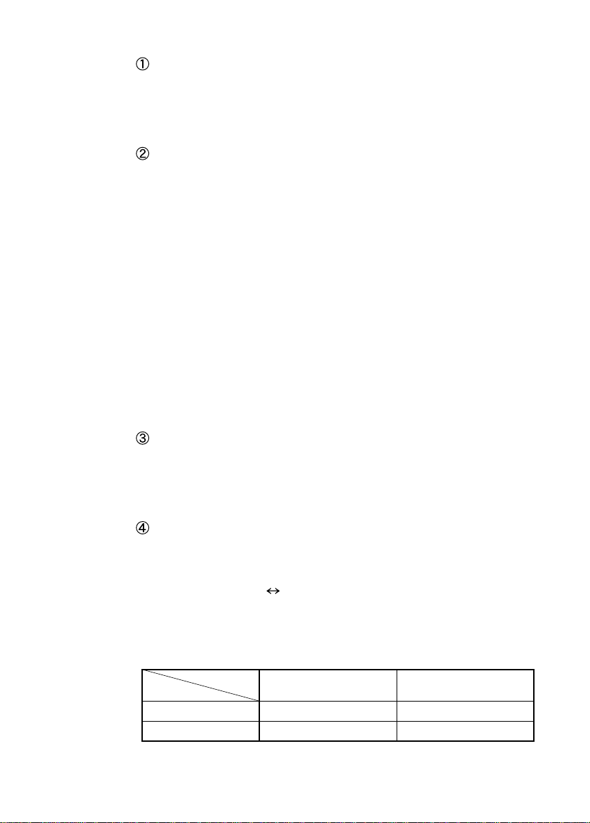
Range switches (500V/200V, 20A/2A)
Selects the range for voltage and current measurements.
At power ON, both ranges are set to Lo (indicator OFF).
Range switch Hi Lo changes each time the button is
pressed. The range for power measurements is a
combination of voltage and current range settings,
determined as follows.
V rang
A range
Lo (2 A) 0.2 kW 2kW
Hi (20 A) 2kW 20 kW
Lo (200 V) Hi (500 V)
―――――――――――――――――――――――――――――――――――
Chapter 1 Overview
Page 14

4
N
y
e
d
―――――――――――――――――――――――――――――――――――――――
Output Terminals
Output is a DC voltage value equivalent to the
measurement value (2 VDC/f.s.).
CH1: Power only (continually outputs regardless of
selected function).
CH2: Outputs the value for the displayed function.
CAUTIO
To avoid damage to the unit, do not short the output
terminal and do not input voltage to the output terminal.
The response waveform for analog output appears as
follows.
Output
voltage
Output stabilit
Tim
Input applie
Voltage, current: T ≒ 1.2 s (when input is 95 % of fullscale)
Power: T ≒ 1.4 s (when input is 95 % of full-scale)
These figures are also applicable when function or range
changes are made.
―――――――――――――――――――――――――――――――――――
Chapter 1 Overview
Page 15

5
N
―――――――――――――――――――――――――――――――――――――――
Measurement Terminal Board
The rear panel terminal board is used to connect the
device under test with the power source. Connection
cables should have sufficient capacity ratings, and be
connected securely (and neatly) to avoid accidental short-
circuits.
Fuse Holder
The instrument takes a 0.5 A/250 V arc-quencing, midget
type fuse. Unplug the power cord when changing the
fuse.
AC Inlet
This receptacle is used to connect the instrument to the
AC power supply (AC mains). Use the power cord
provided with the instrument. The power source rating
for your particular instrument is marked in the table
above the fuse holder. Make sure that this rating agrees
with the power source being used.
Handle
As shown in figure on the next page, the handle may be
rotate by sliding the grip at the sides of the handle in the
direction of the SLIDE TO ROTATE arrow. When the
proper position has been attained, push the slide in the
LOCK arrow direction. The handle may be set at 30
。
detents to fix it in position.
CAUTIO
The handle can be used as a stand to incline the
instrument. Force should not be applied to the
instrument from above when using it in this manner.
―――――――――――――――――――――――――――――――――――
Chapter 1 Overview
Page 16

6
―――――――――――――――――――――――――――――――――――――――
E
T
A
T
O
R
O
T
E
D
I
S
L
Handle
―――――――――――――――――――――――――――――――――――
Chapter 1 Overview
Page 17

7
)
2
s
2
―――――――――――――――――――――――――――――――――――――――
Chapter
Specification
.1 General Specifications
Measurement
functions
Measurement range
Maximum display
value
Crest factor
Meter losses (typical
values, at 55 Hz)
Maximum allowable
input (continuous)
Display
Sampling rate
Accuracy
(23。±5。, 50/60 Hz)
AC voltage, AC current (true rms), single-and
3-phase active (real) power
V
A
12
,A
1
32
3
2 A/20 A
200 V/500 V
,V
W 0.2 kW/2 kW/20 kW
,V
V
12
,A
A
1
199.9 V/500 V
32
1.999 A/19.99 A
3
W .1999 kW/1.999 kW/19.99 kW
V
A
12
,A
1
32
2 or less at full-scale
3
2 or less at full-scale
,V
W Same as voltage and current
V
A
V
A
32
12
0.012 VA at 2 A, 1.3 VA at 20 A
,A
3
1
600V
,V
32
12
30 A
,A
3
1
0.017 VA at 200 V, 0.12 VA at 500 V
,V
3-1/2 digit LED display (1999 max)
Approximately 2.5 samples-per-second
,V
V
12
,A
A
1
±0.5% rdg. ±6 dgt.
32
±0.5% rdg. ±6 dgt.
3
W ±0.5% rdg. ±6 dgt. (power-factor=1.0
Frequency response
,V
V
12
,A
A
1
within ±0.5% rdg., 40 Hz to 1 kHz
32
within ±0.5% rdg., 40 Hz to 1 kHz
3
(≦18 A)
within ±0.5% rdg., 45 Hz to 1 kHz
(>18 A)
―――――――――――――――――――――――――――――――――――
Chapter 2 Specifications
Page 18

8
r
.
―――――――――――――――――――――――――――――――――――――――
Frequency response
Affect of power facto
on accuracy
(50/60 Hz)
Temperature
characteristics
Analog output
Dielectric strength
Rated supply voltage
Affect of power
source voltage
W within ±1.0% rdg., 40 Hz to 1 kHz
(When current input ≦ 18 A, and
power-factor = 1.0)
within ±1.0% rdg., 45 Hz to 1 kHz
(When current input > 18 A, and
power-factor = 1.0)
0.2 kW range within ±1.0% rdg.,
power factor=0.5
2 kW range within ±0.8% rdg.,
power factor=0.5
20 kW range within ±0.8% rdg.,
power factor=0.5
Within ±2.0% rdg. at 0 to 40°
CH1 power only (continual output), 2 VDC/f.s
CH2 selected function, 2 VDC/f.s.
2.2 kVAC/1 min (between input terminals and
case), 1.5 kVAC/1 min (between power
terminals and case)
100/120/220/240 VAC (specify one) 50/60 Hz
(voltage fluctuations of ±15% from the rated
supply voltage are taken into account)
Accuracy of above specifications assured within
specified power source range.
Rated power
Approximately 5.5 W at 100 V, 60 Hz (7 VA
approximately) (3184-02: approximately 9.5 W
(11 VA approx.))
Dimensions
Mass
Accessories
250 (W) × 85 (H) × 220 (D) mm
2.9 kg (3184-02: 3.0 kg)
Fuse (M0.5 A/250 V arc-quencing midget 20 mm
×5.2 mm dia.) ×1
Power cord ×1
Instruction manual ×1
Options
9084 CARRYING CASE
9149 CARRYING CASE
―――――――――――――――――――――――――――――――――――
Chapter 2 Specifications
Page 19

9
r
s
r
r
y
o
l
)
-
r
r
r
r
r
o
)
PT
P
C
CT
V
V
A
A
3
g
le
3
―――――――――――――――――――――――――――――――――――――――
Chapter
Basic Operatin
Princip
.1 Active Power Measurements
12
32
T
1
3
Amplifie
T
Amplifie
Multiplie
Multiplie
Selector
Auto-zer
Auto-zer
Panel switch contro
Analog output (CH1
Rms
converte
Analog output (CH2
Low
pass
filte
Control
A/D
converte
Amplifie
Displa
Figure 3.1-1 Circuit Block Diagram
A block diagram of the various circuits contained in the
3184 is shown in Figure 3.1-1. As shown in the figure,
supply voltage and current of the device under test is
sensed by the PT and CT respectively. These values are
converted to a 2 V/f.s. signal for application to the
multipliers where power is calculated.
―――――――――――――――――――――――――――――――――――
Chapter 3 Basic Operating Principle
Page 20

10
Voltage-Current Waveforms
Power Conversion Waveform
3
―――――――――――――――――――――――――――――――――――――――
The DC component of the calculated waveform is
proportional to active power. Output is obtained by
extracting this DC component and adjusting it to a 2
VDC/f.s. level.
Figure 3.1-2
Figure 3.1-3
.2 Voltage and Current Measurements
In conventional measuring instruments, the method of
measuring an AC signal is to sense its average value,
then make the necessary calculations to convert it to an
rms value. However, using this method does not account
for waveform distortion, or non-true sine waves, normally
resulting in an inaccurate measurement. These
instruments use special rms converters that work by
sampling the instantaneous value of the signal, and thus
produce a true rms reading of the signal.
―――――――――――――――――――――――――――――――――――
Chapter 3 Basic Operating Principle
Page 21

11
3
―――――――――――――――――――――――――――――――――――――――
.3 Crest-Factor
In measuring instruments, the dynamic range of the
meter circuit is expressed as a crest-factor. In
measurements where peak-values are high relative to rms
value, selecting a suitable range for the rms value will
likely result in the waveform peaks exceeding the
dynamic range of the signal. Crest-factor is the ratio of
peak-value to rms value, defined as follows.
Peak-value
Crest-factor =
Rms value
For these instruments, crest-factor is as follows.
): Two or less at full-scale
AC voltage (V
AC current (A
Single-and 3-phase active power (W): Same as voltage and
current.
,V
32
12
): Two or less at full-scale
,A
3
1
For example, when measuring AC current in the Lo range
with the 3184, maximum display value(full-scale) is 2 A,
so maximum allowable peak-value input (maintaining
accuracy) is as follows.
Peak-value = rms value × crest-factor
= 2 [A] × 2 = 4 [A]
When measuring AC voltage in the Hi range full-scale is
500 V, so 500 [V] × 2 = 1000 [V] (peak-value)
The overcurrent and overvoltage warning indicators will
light when input value exceeds the peak-value in the
table on the next page.
―――――――――――――――――――――――――――――――――――
Chapter 3 Basic Operating Principle
Page 22

12
―――――――――――――――――――――――――――――――――――――――
Function Range 3184
NOTE
Voltage
Current
Lo
1000 V peak
Hi
Lo 4 A peak
Hi 40 A peak
If the crest factor in the specification is exceeded, the
displayed data will not be accurate.
―――――――――――――――――――――――――――――――――――
Chapter 3 Basic Operating Principle
Page 23

13
G
N
4
s
4
―――――――――――――――――――――――――――――――――――――――
Chapter
Operating Instruction
.1 Operating Procedure
WARNIN
CAUTIO
In order to prevent electric shock and short-circuit
accidents, shut off the power to the line to be
measured before connecting the load or power
supply to the terminals.
In order to maintain safety and assure the stable
operating performance of this unit, be sure to
connect the ground terminal to a proper ground.
Before turning on the power, make sure that the
voltage of the power supply being used matches the
supply voltage indicated on the rear panel of the
unit.
If an attempt is made to use an improper supply
voltage, there is danger of damage to this unit and
of life-threatening risk to the operator.
・ To avoid damage to the unit, do not input a
voltage/current exceeding the rated maximum to the
terminals.
・ Before measurement, check the position of the range
switch. The unit may be damaged if current or voltage
exceeds the measurement limit is applied for a long
time.
―――――――――――――――――――――――――――――――――――
Chapter 4 Operating Instructions
Page 24

14
―――――――――――――――――――――――――――――――――――――――
NOTE
・ Approximately two seconds is required for display to
reach stability after applying input, or selecting function
or range.
・ Using the instrument in the presence of magnetic fields
(and sometimes meter noise itself) will produce a reading
of a few digits even though input is zero.
・ For an indication of 1999, the analog output is 1.999 VDC
(1 mV/dgt.). Therefore, when measuring 500 V the
indication is 500, and the output is 500 mV.
・ The 3184 uses a voltage transformer (PT) and current
transformer (CT), which do not transmit DC. It is
therefore not possible to measure a signal (for example
full-wave or half-wave rectified) which includes a DC
component.
・ Because of characteristics of the internal circuit design,
when measuring a load which includes a component of a
certain frequency, the power indication may be unstable,
with a periodic fluctuation.
(1) Turn the power switch ON, and allow the instrument
approximately 5 minutes of warm-up prior to starting the
measurement.
(2) Set the range switches according to the expected voltage
and current of the device under test. When this is
unknown, start with a Hi range setting.
(3) Connect the power source and device under test to the
measurement terminal board as illustrated in Figure 4.11 and 4.1-2. Install the protective cover, and turn power
ON to the power source and the device under test.
(4) Use the function switches to select the various functions
for measurement and display.
(5) If the OVER V or OVER A lamps should light while in
the Lo range, switch to the Hi range.
―――――――――――――――――――――――――――――――――――
Chapter 4 Operating Instructions
Page 25

15
―――――――――――――――――――――――――――――――――――――――
(6) When voltage or current in the device under test exceeds
the measurement range of the instrument that you are
using, reduce the level of the input signal using PTs and
CTs connected as illustrated in figure 4.1-3. Note
however, that PTs and CTs produce phase errors that
adversely affect the accuracy of power measurements, and
caution is advised when using this setup.
Power
source
Load
Figure 4.1-1 3-Phase, 3-Wire Connection Procedure
―――――――――――――――――――――――――――――――――――
Chapter 4 Operating Instructions
Page 26

16
―――――――――――――――――――――――――――――――――――――――
Power
source
Figure 4.1-2 Single-Phase Connection Procedure
Power
source
Load
Load
Figure 4.1-3 Connection Procedure Using PTs and CTs
―――――――――――――――――――――――――――――――――――
Chapter 4 Operating Instructions
Page 27

17
5
B
s
5
―――――――――――――――――――――――――――――――――――――――
Chapter
3184-02 GP-I
Specification
.1 Outline
The 3184-02 feature built-in GP-IB interfaces. This
allows the instruments to be connected to a GP-IB system
for automated measurement data reading, and for
program-control of function and range settings. Interface
functions also include the ability to transmit a service
request in the event of an overvoltage or overcurrent.
―――――――――――――――――――――――――――――――――――
Chapter 5 3184-02 GP-IB Specifications
Page 28

18
.
5
―――――――――――――――――――――――――――――――――――――――
.2 Interface Specifications
Applicable standard: IEEE 488-1978
Interface functions:
SH1
AH1
T6
L4
SR1
RL2
PP0
DC1
DT0
C0
(E1)
All SH functions.
All AH functions.
Basic talker function,
Serial poll function,
Unaddress if MLA function.
No talk-only mode function.
Basic listener function,
Unaddress if MTA function
No listen-only mode function.
All SR functions.
Remote/Local switching function
No PP function
All DC functions.
No DT function.
No controller function.
(Open-collector driver.)
―――――――――――――――――――――――――――――――――――
Chapter 5 3184-02 GP-IB Specifications
Page 29

19
5
―――――――――――――――――――――――――――――――――――――――
.3 Panel Description
GP-IB status lamps
When operated under GP-IB system control, these lamps
indicate present device status.
RMT Indicates that the device can be controlled
externally.
SRQ Indicates that the device is transmitting a service
request to the controller.
TLK Indicates that the device is transmitting data as
the talker.
LTN Indicates that the device is receiving data as the
listener.
GP-IB connector
24-pin connector conforming to the IEEE 488 bus
standard. Used with a standard bus cable.
Address switch
Used to set the device address for the GP-IB system.
(Left-hand switch not usable.)
―――――――――――――――――――――――――――――――――――
Chapter 5 3184-02 GP-IB Specifications
Page 30

20
5
―――――――――――――――――――――――――――――――――――――――
.4 Talker Function
Output data format
±DDDDDE±D CR LF
AAA
(1) (2) (3)
(1) Measurement Functions
Header
V
V
A
A
NO Indicates no setting has been made.
OVR Overrange
V12(Voltage measurement)
12
V32(Voltage measurement)
32
A1(Current measurement)
1
A3(Current measurement)
3
W W (Power measurement)
(2) Measurement Values
Measurement
function
V12,V
32
A1,A
3
W
Range Mantissa Exponent
200 V +ddd.d E+0
500 V +dddd. E+0
2A +d.ddd E+0
20 A +dd.dd E+0
0.2 kW ±ddd.d E+0 *
2kW ±d.ddd E+3
20 kW ±dd.dd E+3
Function
Note: Data marked by asterisk (*) is formatted different
than the examples shown on the instrument’s
instruction label.
Output data for an overrange is as follows.
OVR 19999. E + 9
―――――――――――――――――――――――――――――――――――
Chapter 5 3184-02 GP-IB Specifications
Page 31

21
5
―――――――――――――――――――――――――――――――――――――――
(3) Delimiter
"CR" and "LF" are sent as delimiters. An EOI is
transmitted simultaneous with "LF".
.5 Listener Functions
Programming code
(1) Function
F0
F1
F2
F3
F4
F5
(2) Range
Voltage range
Current range
(3) Service Request
S0
S1
No service request mode.
Service request mode set.
Function not set.
V
12
V
32
A
1
A
3
W
V0 Lo 200 V
V1 Hi 500 V
A0 Lo 2A
A1 Hi 20 A
(4) Header Output
H0
H1
No header output mode.
Header output mode set.
―――――――――――――――――――――――――――――――――――
Chapter 5 3184-02 GP-IB Specifications
Page 32

22
―――――――――――――――――――――――――――――――――――――――
Programming precautions
Delimiter Usage
When receiving data as the listener, the incoming
transmission will be interrupted for internal processing in
the following two cases.
・When an "EOI" is received.
・When an "LF" is received.
This is disregarded for a "CR". (An unaccompanied "CR"
is only effective in breaking the incoming transmission for
internal processing when the LACS (Listener Active
State) is terminated.)
Note also that when programmed backwards (i.e., "LF"
"CR"), the break in transmission when "LF" is received
leaves "CR" on the bus, and this is likely to lock the next
handshake routine.
Syntax Errors
When undefined codes, or strings of over 21 characters
are received, the syntax error bit in the status byte will
be set, and if the "S1" mode is programmed, a service
request will be sent.
Setting Time Requirements
When setting function and range externally, these
settings will be made after all codes have been received,
requiring a maximum of 2.5 ms. Operation commands
received during that interval will not be properly
executed.
Note also that approximately 2 seconds is required for the
display to stabilize after a voltage or current input, or
whenever a function or range change is made. That
amount of wait time must be allowed in the program.
(Response time for analog output is noted in Section 1.2,
"Names and Functions of Parts.")
―――――――――――――――――――――――――――――――――――
Chapter 5 3184-02 GP-IB Specifications
Page 33

23
S
X
R
O
A
O
V
l
5
―――――――――――――――――――――――――――――――――――――――
.6 Service Requests
When the "S1" mode is set, a service request will be sent
in the event of an overvoltage or overcurrent input, or for
programming errors such as undefined codes or format
errors.
Following transmission of the service request, the
controller sends a serial poll, and the device responds by
transmitting its status byte and resetting the SRQ bit (bit
6).
When "S0" is set, a service request is not sent, but the
status byte is transmitted.
The OVER V or OVER A bit (bit 0 and 1) will be reset
with the serial poll, but a SYNTAX ERROR bit (bit 2)
remains until the next time the device is designated as
the listener, at which time it is reset.
Status Byte
Bit 7 6 5 4 3 2 1 0
0 SRQ 0 0 0
Service request sent Undefined code, or code
containing over 21 characters
received
Overvoltage input 01000001 65
Overcurrent input 01000010 66
Undefined code received 01000100 68
, , and occurring together01000111 71
―――――――――――――――――――――――――――――――――――
Chapter 5 3184-02 GP-IB Specifications
YNTA
ERRO
VER
Overcurrent input
Binary Decima
VER
Overvoltage input
Page 34

24
5
―――――――――――――――――――――――――――――――――――――――
.7 Usage Precautions
(1) Address setting
The GP-IB address for the device with this interface is set
using the rear panel DIP switch. Any address 0 thru 30
not used by another device in the system can be used.
The ON side of the switch represents "1", and the OFF
side "0". Addresses are set using the five right switches
as shown in the following table.
Address 54321 Address 54321 Address 54321
0 00000 11 01011 21 10101
1 00001 12 01100 22 10110
2 00010 13 01101 23 10111
3 00011 14 01110 24 11000
4 00100 15 01111 25 11001
5 00101 16 10000 26 11010
6 00110 17 10001 27 11011
7 00111 18 10010 28 11100
8 01000 19 10011 29 11101
9 01001 20 10100 30 11110
10 01010
NOTE
The device address is read into the system when the
power turned ON. Consequently, whenever address
changes are made, power must be turned OFF, then back
ON for the new address to be effective.
―――――――――――――――――――――――――――――――――――
Chapter 5 3184-02 GP-IB Specifications
Page 35

25
5
―――――――――――――――――――――――――――――――――――――――
(2) Items Regarding Local and Remote Control
a. When switching between local and remote control,
function and range settings remain the same.
b. In the remote status, all panel controls (except the power
switch) are ineffective.
c. Measurement data is output according to function and
range setting, and has no bearing on remote or local
status.
.8 Sample Programs
The program below is written for an HP-9816 computer.
It assumes that the address for the 3184 is "1".
(1) HP-9816 serves to read the value for power from the
power meter, and direct print-out.
Overvoltage and overcurrent is tested for each sample.
10 DIM A$[20], B$[4]
20 ON INTR 7 GOSUB 120
30 CLEAR 701
40 OUTPUT 701;"F5V1A0H1S1"
50 B$=""
60 ENABLE INTR 7:2
70 WAIT 2
80 ENTER 701;A$
90 PRINT A$.B$
100 GOTO 50
110 !
120 S=SPOLL (701)
130 IF S>64 THEN B$="OVER"
140 RETURN
150 END
―――――――――――――――――――――――――――――――――――
Chapter 5 3184-02 GP-IB Specifications
Page 36

26
―――――――――――――――――――――――――――――――――――――――
Program Explanation
10 Defines the data area.
20 Defines the subroutine used when an OVER V/A
interrupt occurs.
30 Initializes the power meter.
40 Sets W as function, range for voltage Hi, current
Lo, header output, and service request mode.
50 Resets memory used for detecting OVER V/A.
60 Enables interrupt.
70 Wait for two seconds.
80 Reads data.
90 Prints out data.
100 Returns to line 50.
110 REM statement.
120 Polls the power meter, reads the status byte.
130 If OVER V/A has occurred, sets "OVER" in B$.
140 Returns to main routine.
150 Ends program.
―――――――――――――――――――――――――――――――――――
Chapter 5 3184-02 GP-IB Specifications
Page 37

27
―――――――――――――――――――――――――――――――――――――――
(2) With this program, HP-9816 reads voltage, current, and
power(single-phase) from the power meter and uses this
data to calculate power-factor. Input is taken from V
and A
.
1
12
10 CLEAR 701
20 OUTPUT 701;"F1V0A0H0S0"
30 WAIT 2
40 ENTER 701;V
50 PRINT V;"V"
60 OUTPUT 701;"F3"
70 WAIT 2
80 ENTER 701;A
90 PRINT A;"A"
100 OUTPUT 701;"F5"
110 WAIT 2
120 ENTER 701;W
130 PRINT W;"W"
140 PRINT USING "14A,Z,2D"; "Power Factor", W/(V*A)
150 END
Program Explanation
10 Initializes the power meter.
20 Sets V
as function, Lo range for both voltage and
12
current. No header output, no service request.
30 Allows two seconds for display to stabilize.
40 Reads data.
50 Prints out data.
60 - 130 Data from A 1 and W processed like V
.
12
140 Calculates power-factor, and prints out according to
prescribed format.
150 Ends program.
―――――――――――――――――――――――――――――――――――
Chapter 5 3184-02 GP-IB Specifications
Page 38

28
―――――――――――――――――――――――――――――――――――――――
―――――――――――――――――――――――――――――――――――
Chapter 5 3184-02 GP-IB Specifications
Page 39

29
G
6
d
e
6
―――――――――――――――――――――――――――――――――――――――
Chapter
Maintenance an
Servic
.1 Fuse Replacement
WARNIN
To avoid electric shock, disconnect the power cord
and the input cord from the connectors before
replacing the fuse.
Only use fuses of the specified type that is rated for
the specified current and voltage. Using a fuse that
does not meet the specifications or shorting the
fuse holder may cause an accident that might result
in injury or death.
M0.5 A/250 V (arc-quencing midget) 20 mm × 5.2
mm dia.
―――――――――――――――――――――――――――――――――――
Chapter 6 Maintenance and Service
Page 40

30
N
6
―――――――――――――――――――――――――――――――――――――――
Replacing the Fuse
.2 Service
CAUTIO
―――――――――――――――――――――――――――――――――――
Chapter 6 Maintenance and Service
If the unit is not functioning properly, check the batteries
and fuse blowing. If a problem is found, contact your
dealer or HIOKI representative. Pack the unit carefully so
that it will not be damaged during transport, and write a
detailed description of the problem. HIOKI cannot bear
any responsibility for damage that occurs during
shipment.
Page 41

Page 42

 Loading...