

Page 1

INSTRUCTION MANUAL
3181-01
DIGITAL POWER HiTESTER
Page 2

Page 3

Contents
Introduction i
Inspection i
Safety Notes ii
Notes on Use iii
Chapter 1 Introduction 1
1.1 Features 2
Chapter 2 Specifications 3
Chapter 3 Principle of Operation 5
3.1 Power Measurement 5
3.2 Current and Voltage Measurement 7
3.3 Integrated Watt Value 8
3.4 Crest Factor 10
Chapter 4 Names and Functions of Parts 11
Chapter 5 Operation 19
5.1 Preparing for Measurement 19
5.2 Power, Current and Voltage Measurement 22
5.3 Integrated Watt Value Measurement 23
Chapter 6 Applications 27
6.1 Determing the Power Factor 27
6.2 Connecting the Recorder 27
6.3 Printer Connection 28
6.4 External Control Terminal 30
6.5 Data Output Connector 31
6.6 Inputs Exceeding the Measurement Range 34
6.7 Three-Phase Three-Wire Connection 35
Page 4

Chapter 7 Maintenance and Service 37
7.1 Battery Replacement 37
7.2 Fuse Replacement 39
7.3 Cleaning 40
7.4 Service 40
Page 5

―――――――――――――――――――――――――――――――――――――――
I
I
ntroduction
Thank you for purchasing this HIOKI "3181-01 DIGITAL
POWER HiTESTER ." To get the maximum performance
from the unit, please read this manual first, and keep
this at hand.
nspection
When the unit is delivered, check and make sure that it
has not been damaged in transit. If the unit is damaged,
or fails to operate according to the specifications, contact
your dealer or HIOKI representative.
Accessory
Instruction Manual 1
Power cord 1
i
―――――――――――――――――――――――――――――――――――
Inspection
Page 6

ii
R
G
N
S
―――――――――――――――――――――――――――――――――――――――
afety Notes
This Instruction Manual provides information and
warnings essential for operating this equipment in a safe
manner and for maintaining it in safe operating
condition. Before using this equipment, be sure to
carefully read the following safety notes.
Safety symbols
In the manual, this mark indicates explanations
which it is particularly important that the user read
before using the equipment.
The following symbols are used in this Instruction
Manual to indicate the relative importance of cautions
and warnings.
Indicates that incorrect operation presents extreme
DANGE
danger of accident resulting in death or serious
injury to the user.
Indicates that incorrect operation presents
WARNIN
significant danger of accident resulting in death or
serious injury to the user.
Indicates that incorrect operation presents
CAUTIO
possibility of injury to the user or damage to the
equipment.
NOTE
Denotes items of advice related to performance of
the equipment or to its correct operation.
―――――――――――――――――――――――――――――――――――
Safety Notes
Page 7

―――――――――――――――――――――――――――――――――――――――
R
G
.
N
iii
otes on Use
In order to ensure safe operation and to obtain maximum
performance from the unit, observe the cautions listed
below.
DANGE
WARNIN
Always connect the voltage cable to the secondary
side of a breaker. On the secondary side of a
breaker, even if the lines are shorted the breaker
can trip and prevent an accident. On the primary
side, however, the current capacity may be large,
and in the event of a short-circuit there may be a
serious accident.
This unit cannot be used on voltage lines of 250
Vrms. If the voltage exceeds 250 VAC, there will be
a short-circuit accident or electrocution accident
will result.
In order to prevent an electrical accident, do not
make any connections while the power supply or
the device to be measured is on. Turn off the
power for both devices before proceeding.
The power supply voltage for this unit is switchable
To avoid electrical accidents, check that the voltage
selector is set correctly for the supply voltage you
are using.
In order to maintain safety and assure the stable
operating performance of this unit, be sure to
connect the ground terminal to a proper ground.
―――――――――――――――――――――――――――――――――――
Notes on Use
Page 8

iv
N
―――――――――――――――――――――――――――――――――――――――
CAUTIO
NOTE
・ Before measurement, check the position of the range
switch. The unit may be damaged if current or voltage
exceeds the measurement limit is applied for a long
time.
・ Before using the unit, make sure that the sheathing on
the leads is not damaged and that no bare wire is
exposed. If there is damage, replace it with a new one.
・ Do not store or use the unit where it will be exposed to
direct sunlight, high temperatures, high humidity, or
condensation. If exposed to such conditions, the unit
may be damaged, the insulation may deteriorate, and
the unit may no longer satisfy its specifications.
・ To avoid damage to the unit, do not short the output
terminal and do not input voltage to the output terminal.
・ After initiating watthour measurement by pressing the
start button, do not alter the settings of the range switch,
the time setting dial or the time unit switch.
・ The 3181-01 is not certified for commercial metering.
・ The 3181-01 uses a voltage transformer (PT) and current
transformer (CT), which do not transmit DC. It is
therefore not possible to measure a signal (for example
full-wave or half-wave rectified) which includes a DC
component.
・ Do not use the 3181-01 to measure equipment with
ratings outside its ranges or whose current consumption
continuously exceeds 15A.
―――――――――――――――――――――――――――――――――――
Notes on Use
Page 9

1
1
n
―――――――――――――――――――――――――――――――――――――――
Chapter
Introductio
The 3181-01 is a compact, multifunction power meter
providing power, current, voltage and watthour
measurements on equipment such as consumer products.
Current and voltage are indicated as true rms values,
enabling accurate measurements even on distorted
waveforms.
The integrator contains a timer allowing integration time
to be set in ranges 1 to 99 minutes or 1 to 99 hours. With
several output terminals, the 3181-01 can be linked to a
data recorder or a printer, enabling easy recording of
measurement data.
―――――――――――――――――――――――――――――――――――
Chapter 1 Introduction
Page 10

2
1
―――――――――――――――――――――――――――――――――――――――
.1 Features
(1) Power, current, voltage and watthour measurements in a
single unit
(2) True rms reading of voltage and current values
unaffected by distorted waveforms
(3) Integrator timer can be set in ranges 1 to 99 minutes or 1
to 99 hours. (set timer at 00 for continuous integration)
(4) Auto-zero circuit ensures accurate power and watthour
measurements over long time spans.
(5) Three simultaneous outputs for power, current and
voltage
(6) Connecting the optional 3171 DIGITAL PRINTER to the
data output connector makes it possible to record power
consumption and average power values over time.
(7) Watthour data is protected against power failures by a
battery backup function.
(8) Compact, lightweight and highly portable
―――――――――――――――――――――――――――――――――――
Chapter 1 Introduction
Page 11

3
,
)
2
s
―――――――――――――――――――――――――――――――――――――――
Chapter
Specification
Display (Power meter) 1999 digit LCD
(Integrator) 999999 digit LCD
Sampling rate (Power meter) Approx. 3 samples/s
Measurement
functions
Timer setting ranges (Integrator) 1 to 99 min/1 to 99 h
Timer accuracy (Integrator) ±0.01 %±1 s (at 0℃ to 40℃)
Measurement range (Power meter) Power: 200/2000 W
Accuracy (Ambient
temperature: 23℃±5℃
line power: 50/60 Hz,
power factor: 1.0)
Frequency response
(40 to 500 Hz)
Influence of power
factor
Temperature
characteristics (in
range 0 to 40 ℃)
Maximum circuit
voltage
(Power meter) Single-phase active power
AC current and AC voltage (rms
reading)
(Integrator) Watthour value
Current: 2/20 A
Voltage: 0 to 250 V (resolution 1 V)
(Integrator) Lo: 200 W range 103/105Wh
Hi: 2000 W range 104/106Wh
(Power meter) Power: ±0.5% of rdg. ±0.3% of f.s.
Current: ±0.5% of rdg. ±0.3% of f.s.
Voltage: ±0.7% rdg. ±1 dgt.
(Integrator) ±1% rdg. ±1 dgt. (at input of 2.5% to
120% of f.s.)
(Power meter) Power: ±1% of max (power factor 1.0
Current, Voltage: ±0.5 % max
(Power meter) ±0.8% of rdg. max (power factor 0.5)
(Power meter) ±0.1% f.s./℃ max
(Integrator) ±0.05% f.s./ ℃ max
(Power meter) 250 Vrms
―――――――――――――――――――――――――――――――――――
Chapter 2 Specifications
Page 12

4
―――――――――――――――――――――――――――――――――――――――
Rated current (Power meter) 15 Arms (continuous rating)
Crest factor (Power meter) Power, current: 2 max at maximum
display or 30 A peak (lower value)
Voltage: 500 V peak value max
Output terminals (Power meter) 2 VDC/f.s. 2 VDC output for 200 V
input in voltage function only.
(Integrator) Hi: 5V, Lo: 0 V CMOS level
External control
terminal
Dielectric strength AC 2.4 kV/1 min (between input terminals and case)
Power supply 100, 120, 220, 240 VAC ±15%, 50/60 Hz
Rated power Approx. 3.5 W
Effect of power supply
voltage
Backup power R6P manganese batteries×3 (supplies more than 100
Dimensions Approx. 218 (W) × 85 (H) × 240 (D) mm
Mass 2.6 kg
Accessories Power cord 1
Options 3171 DIGITAL PRINTER
(Integrator) OFF: Open (or Hi: 5 V)
ON: Closed (or Lo: 0V)
Specified accuracy satisfied within above specified
line voltage ranges.
hours backup capability)
(excluding protrusions)
Instruction Manual 1
9084 CARRYING CASE
9149 CARRYING CASE
―――――――――――――――――――――――――――――――――――
Chapter 2 Specifications
Page 13
5
y
h
3
n
3
―――――――――――――――――――――――――――――――――――――――
Chapter
Principle of Operatio
.1 Power Measurement
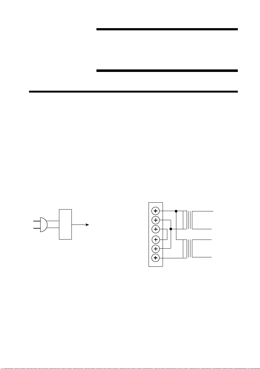
Figure 3.1-1 and 2 show the block diagram. The line
voltage and current of the device under measurement are
detected by a voltage transformer (PT) and current
transformer (CT), respectively. The resulting detected
signals are voltage-level converted and input to a
multiplier. Since the DC component of the output of this
multiplier is proportional to the active power, after the
level is adjusted, this is displayed and output as the
power value.
Power suppl
To eac
section
Figure 3.1-1 The Block Diagram 1
INPUT
OUTPUT
PT
To V IN
To A IN
CT
―――――――――――――――――――――――――――――――――――
Chapter 3 Principle of Operation
Page 14
6
e
n
o
s
r
e
n
3
it
3
it
r
r
Power output
Voltage output
Current output
To VF converter
V IN
A IN
r
z
e
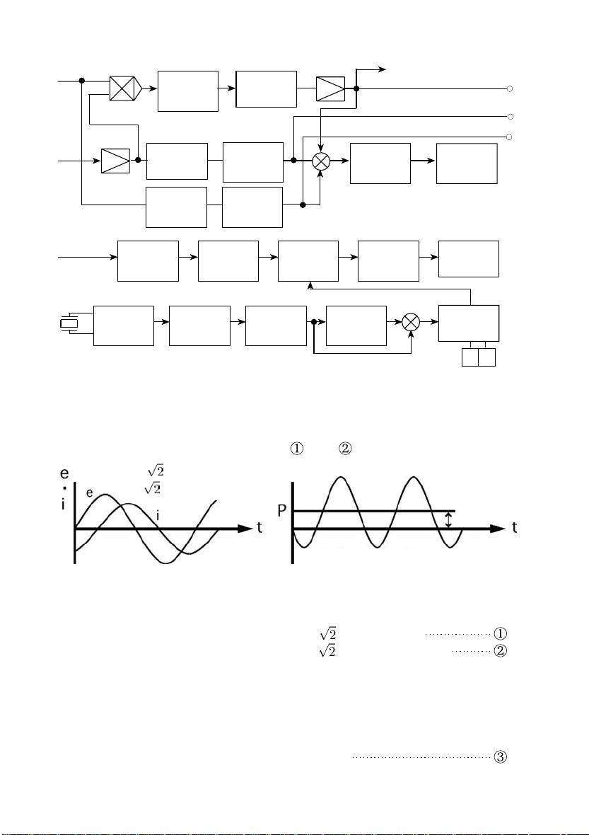
Figure 3.1-2 The Block Diagram 2
)
)
θ
―――――――――――――――――――――――――――――――――――――――
Low-pas
filter
Rms
conversio
Rms
conversio
Division
(106)
1 s pulse 1 min pulse 1 h puls
6-digit
counter
Division
(60)
-1/2 dig
A-D
Decode
driver
Division
(60)
Multiplie
VF
converte
32.768 kH
Clock
oscillato
Auto-zer
Absolut
value
Absolut
value
Division
(215)
The voltage and current waveforms in Figure 3.1-3 are
described by equations and .
e = Ecosωt
i = lcos(ωt+θ
-1/2 dig
LCD
6-digit
LCD
Timer
9 9
P=Elcos
P=e・i=Elcosθ+ Elcos(2ωt+θ
Figure 3.1-3 Power Calculation Waveform
Sinewave AC voltage e = Ecosωt [V]
Sinewave AC current i = Icos(ωt+θ) [A]
The product of e and i representing the voltage-current
product is the instantaneous power.
Instantaneous power p = e・i = 2EIcosωt・cos(ωt+θ)
= EIcos(2ωt+θ) + EIcosθ
[W]
―――――――――――――――――――――――――――――――――――
Chapter 3 Principle of Operation
Page 15
7
r
o
a
E
)
─────
3
―――――――――――――――――――――――――――――――――――――――
Thus, the active power P = EIcosθ [W] is the DC
component of the product of the voltage and current (the
second term in equation ( )).
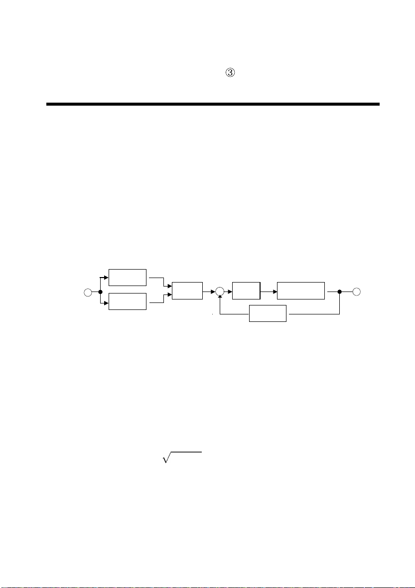
.2 Current and Voltage Measurement
When measuring AC signals using a general-purpose
measuring instrument, an average-value detection is
performed, after which conversion to the rms value is
made. Therefore, measurements on distorted or otherwise non-sinusoidal waveforms will result in errors. In
the 3181-01, the true rms value is read by an absolute
value detection circuit and a true rms value conversion
circuit.
lnx
Ei(t)
lnx
+
x
e
ー
L. P. Fadde
lnx
True Rms Conversion Circuit
In the true rms conversion circuit shown in the figure
above, if we observe point a, we find the following
relationship.
─────
ln Ei(t)
──────
ln Ei2(t)
∴ Eo =
────
+ln E(t)
=lnEo
2
i2(t
- ln Eo = ln Eo
Now let Ei(t) be the result of performing absolute-value
detection on the voltage and current signals from the
voltage transformer and current transformer, then the
output voltage Eo is proportional to the voltage-current
rms value.
―――――――――――――――――――――――――――――――――――
Chapter 3 Principle of Operation
E
Page 16

8
3
―――――――――――――――――――――――――――――――――――――――
.3 Integrated Watt Value
The DC voltage Ei(2 V f.s.) is proportional to the power
measured by the power meter. The V-F converter
converts Ei into a pulse train, the pulses are counted by
the counter and the result is displayed as the watthour
value. (V-F conversion rate α = 27.7....(Hz/V))
For example, if 100 [W] is the power measured in the low
range (200 [W] f.s.), the voltage Ei input to the V-F
converter is given by the following formula.
Ei = 2 [V](f.s.)×100 [W] /200 [W]= 1 [V]
The time-unit switch on the 3181-01 front panel is also
the integrator RANGE switch. If integration is
performed at Wh:Lo (TIME:MIN) for one hour, the
resulting integration value N is calculated thus:
N=α [Hz/V]×Ei [V]×T [s]
= 27.7.... [Hz/V]× 1 [V]× 3600 [s]
= 100000
By interlocking ranges and setting the decimal point at
the fourth digit from the right, it is possible to directly
display watthour values of up to 100.000 Wh. If
integration is performed for one hour with Wh:Hi
(TIME:HOUR) set, after the divide-into-100 circuit, the
following value is obtained:
N = 27.7.... [Hz/V]× 1 [V]× 3600 [s]× 1/100
= 1000
If the decimal point is set at the second digit from the
right in this case, the value 100.0 Wh is displayed. As
the above discussion shows, the maximum display value
of the integrator can be changed by different
combinations of time units and ranges (table on the next
page).
―――――――――――――――――――――――――――――――――――
Chapter 3 Principle of Operation
Page 17

9
e
―――――――――――――――――――――――――――――――――――――――
The Wh/TIME and the time setting dial on the 3181-01
front panel are used to set the integration time in the
range 1 to 99 minutes or 1 to 99 h. Once the desired time
is set, pressing the START switch resets the internal
circuits and integration begins. When the set time is
reached, the counter output is put on hold. If the
integrator is started with the timer set to "00", it
performs continuous integration. The HOLD/RUN switch
on the front panel is used to stop the counter and start
again. Below the V-F converter there is a backup battery
which maintains continuous operation in the event of a
power failure, so there is no danger of loosing watthour
values measured up to the power failure.
Integrator Maximum Display Values
Rang
Time unit
TIME: MIN
Wh: Lo
TIME: HOUR
Wh: Hi
―――――――――――――――――――――――――――――――――――
Lo(200W) Hi(2000W)
999.999 Wh 9999.99 Wh
99999.9 Wh 999999 Wh
Chapter 3 Principle of Operation
Page 18

10
3
―――――――――――――――――――――――――――――――――――――――
.4 Crest Factor
Crest factor is a measure of the dynamic range of a
measurement. In measurements in which the peak value
is high but the rms value is low, if the measuring
instrument range is selected based on the rms value,
waveform peaks will exceed the dynamic range of the
circuit, causing errors since the circuit is not operating
linearly in this region.
The relation between the crest factor, peak value and rms
value is defined as follows.
Crest factor = Peak value/rms value
The 3181-01 has the following specifications.
AC voltage
AC current
Single-phase
active power
For example, using the 3181-01 to measure AC current in
the Lo range, since the maximum display value is 2 A,
the largest allowable peak value on the input being
measured can be calculated as follows.
From the definition,
Peak value = rms value × crest factor
500 V peak value max
2 max at maximum display value or 30 A
peak (lower value)
same as for voltage and current
=2× 2
= 4 [A]
―――――――――――――――――――――――――――――――――――
Chapter 3 Principle of Operation
Page 19

11
Rear Panel
910111213
1415161718
Front Panel
123
45678
4
of
ts
―――――――――――――――――――――――――――――――――――――――
Chapter
Names and Functions
Par
―――――――――――――――――――――――――――――――――――
Chapter 4 Names and Functions of Parts
Page 20

12
123
4
e
―――――――――――――――――――――――――――――――――――――――
POWER switch
Allow approximately five minutes of warm-up before
performing measurements.
POWER METER display
This 3 1/2 digit LCD display has a maximum display
value of 1999. The function switches are selected to
enable it to indicate measured voltage, current and power
values.
If the input exceeds the maximum display value, the
uppermost digit will appear as 1 and the decimal point
will be displayed, while the lower three digits will be
blanked.
If the voltage of the backup battery falls below 4 V, BATT
will appear in the lower left corner.
INTEGRATOR display
This 6-digit LCD display has a maximum display value of
999999. If the integration value exceeds this, the decimal
point will occupy the uppermost digit. It will blink at
approximately one-second intervals, and integration will
start again from 000000. The colon (:) after the second
digit from the left blinks when the display is running at
approximately one-second intervals, and is blanked when
the display is on hold.
RANGE and functions (WATT, ACA, ACV) switches
These switches are used to switch the display between
power, current and voltage.
Range
switch
Hi
Lo
Function
switch
WATT 1999 W
AC A 19.99 A (Rating is 15 A)
WATT 199.9 W
AC A 1.999 A
Maximum display valu
―――――――――――――――――――――――――――――――――――
Chapter 4 Names and Functions of Parts
Page 21

13
567
―――――――――――――――――――――――――――――――――――――――
The maximum display values for voltage measurements
are independent of RANGE switch settings and are ACV:
"1999" V (0 to 250 V)
START switch
Immediately the START switch is pressed the watthour
value accumulated up to that time is cleared and
integration begins anew from 000000.
Start has priority over hold, so if the INTEGRATOR display
is on hold when the START switch is pressed, integration
begins immediately from zero.
HOLD/RUN switch
This button stops the INTEGRATOR display and clears the
hold condition. When the HOLD/RUN switch is pressed,
the INTEGRATOR display value is held. If the button is
pressed a second time, the display returns to the
watthour value accumulated from the time integration
began and display is continued.
If the INTEGRATOR display is held because the preset time
period has elapsed, this button cannot be used to release
the hold condition.
This is an important point, because if a mistake is made
pressing the start and HOLD/RUN switches, the watthour
value is invalidated.
Wh/TIME switch (time unit switch)
This switch is used to change the time unit for the time
setting dial described in the next section and the
integrator range simultaneously.
Switch setting TIME Wh
HOUR Hi
MIN Lo
Refer to Sections 3.3, "Integrated Watt Value" and 5.3,
"Integrated Watt Value Measurement."
―――――――――――――――――――――――――――――――――――
Chapter 4 Names and Functions of Parts
Page 22

14
8
910
―――――――――――――――――――――――――――――――――――――――
TIME SET dial
This dial is used with the Wh/TIME to set the integration
time interval.
For example, if the
Wh/TIME is set at HOUR and the time
setting dial is set to 24, integration is performed
continuously for 24 hours after the integrator
START
switch is pressed and then automatically stops.
If the dial is set to "00", the timer does not operate and
continuous integration is performed.
Data output connector[DATA OUTPUT]
(Integrated watt value measurements only)
This connector is used to connect the 3171. Do not
connect any other equipment to this connector, as
applying voltage to or shorting the terminals of this
connector can cause damage.
Battery compartment[BATTERY BOX]
This holds the three R6P manganese batteries used for
power backup. The batteries have a life of more than 100
hours when run continuously. BATT shown in the lower
left corner of the power display indicates that the backup
batteries have run down. When this happens, the
batteries must be replaced immediately. (Refer to Section
7.1, "Battery Replacement.")
If the power switch is turned on while the AC plug is
disconnected, only the INTEGRATOR display will operate.
This indicates that the backup power batteries are
functioning normally, it is not a fault. However,
operation without the AC plug inserted should not be
continued for any length of time, as it will run down the
backup batteries.
―――――――――――――――――――――――――――――――――――
Chapter 4 Names and Functions of Parts
Page 23

15
1
N
Output voltage
Input
applied
Time
Output ≒ stabilized
Response Time
2
G
―――――――――――――――――――――――――――――――――――――――
1
Output terminals [OUTPUT]
CAUTIO
To avoid damage to the unit, do not short the output
terminal and do not input voltage to the output terminal.
These output terminals output DC voltages proportional
to the measured values of current and power (2 VDC/f.s.).
The voltage output (Ch1) is 2 VDC for 200 VAC.
The three channels are output simultaneously, regardless
of the setting of the function switches. These channels
are assigned as follows.
CH1: AC voltage
CH2: AC current
CH3: Active power
The output response time is as follows.
WARNIN
―――――――――――――――――――――――――――――――――――
T ≒ 2.3 s for voltage and current
T ≒ 3.3 s for power
1
Ground terminals [
]
In order to maintain safety and assure the stable
operating performance of this unit, be sure to
connect the ground terminal to a proper ground.
Chapter 4 Names and Functions of Parts
Page 24

16
314151617
―――――――――――――――――――――――――――――――――――――――
1
Fuse holder
The 3181-01 requires a fuse with ratings of 250 V and 3 A.
The 3181-01 power cord must be removed from the socket
before replacing the fuse. (Refer to Section 7.2, "Fuse
Replacement.")
Voltage selector
This is used to select the line voltage for the 3181-01.
Ensure that the number indicating the line voltage
selection is aligned with the arrow (↑) below the selector
switch.
AC inlet
This inlet is used to apply line power to the instrument
using the accessory power cord. A line filter and a fuse
are built in.
Measuring terminal
These terminals are used to make connection between the
power line and the equipment being measured. When
making connections, always use conductors which have
sufficient current carrying capacity, tighten them securely
and be careful to avoid looseness and shorts.
External control terminal[EXT.CONTROL]
Leave this terminal open (or at Hi level: 5 V) during
normal operation. It is closed (or at Lo level: 0 V) during
integration to obtain the watthour value for the specified
time period. As soon as this terminal is closed, the
instrument goes directly into operation as if the START
switch had been pressed. That is, the integration value
accumulated up to that moment is cleared and integration
is begun anew. If the external control terminal is opened
during integration, the instrument behaves just as if the
HOLD/RUN switch had been pressed and the accumulated
integration value is displayed. (Refer to Section 6.4,
"External Control Terminal.")
―――――――――――――――――――――――――――――――――――
Chapter 4 Names and Functions of Parts
Page 25

17
8
N
―――――――――――――――――――――――――――――――――――――――
1
Handle
CAUTIO
The handle can be used as a stand to incline the
instrument. Force should not be applied to the
instrument from above when using it in this manner.
As shown in the figure below, the handle may be rotated
by sliding the grip at the sides of the handle in the
direction of the SLIDE TO ROTATE arrow. When the
proper position has been attained, push the slide in the
LOCK arrow direction. The handle may be set at 30 °
detents to fix it in position.
E
T
A
T
O
R
O
T
E
D
S
I
L
Handle
―――――――――――――――――――――――――――――――――――
Chapter 4 Names and Functions of Parts
Page 26

18
―――――――――――――――――――――――――――――――――――――――
―――――――――――――――――――――――――――――――――――
Chapter 4 Names and Functions of Parts
Page 27

19
G
.
5
n
5
―――――――――――――――――――――――――――――――――――――――
Chapter
Operatio
.1 Preparing for Measurement
WARNIN
NOTE
The power supply voltage for this unit is switchable
To avoid electrical accidents, check that the voltage
selector is set correctly for the supply voltage you
are using.
In order to prevent an electrical accident, do not
make any connections while the power supply or
the device to be measured is on. Turn off the
power for both devices before proceeding.
In order to maintain safety and assure the stable
operating performance of this unit, be sure to
connect the ground terminal to a proper ground.
To avoid damage to the unit, do not input a
voltage/current exceeding the specified maximum to
the input terminals.
Because of the internal circuit design, measurement of
load with a certain frequency component will cause cyclic
fluctuation (instability) in the power reading.
This has been observed especially for distorted waveforms
with large harmonic components in multiples of 512 Hz.
―――――――――――――――――――――――――――――――――――
Chapter 5 Operation
Page 28

20
―――――――――――――――――――――――――――――――――――――――
(1) First make sure that the voltage selector switch agrees
with the line voltage before measuring.
(2) Connect the power lines and the equipment to be
measured to the measurement terminal strip as shown in
Figure 5.1-1 or 5.1-2 (either way).
When measuring only voltage or current, refer to Figure
5.1-3 or 5.1-4.
(3) Turn the power on.
(4) Leave the instrument powered ON for approximately five
minutes of warm-up.
(5) Set the RANGE switches appropriate to the current level of
the equipment to be measured.
(Lo range: 2 A max; Hi range: 15 A max). If these are not
known, select the Hi range.
SOURCE
LOAD
(Equipment to
be measured)
Figure 5.1-1 Power, Current and Voltage Measurement
―――――――――――――――――――――――――――――――――――
Chapter 5 Operation
Page 29

21
―――――――――――――――――――――――――――――――――――――――
SOURCE
LOAD
Figure 5.1-2 Power, Current and Voltage Measurement
SOURCE
LOAD
Figure 5.1-3 Voltage Measurement Only
―――――――――――――――――――――――――――――――――――
Chapter 5 Operation
Page 30

22
5
―――――――――――――――――――――――――――――――――――――――
SOURCE
Figure 5.1-4 Current Measurement Only
.2 Power, Current and Voltage
Measurement
Once all preliminaries have been completed, power,
current, and voltage are measured simply by setting the
function switches.
If the display scale exceeds in the Lo range when power
and current are being measured, switch the range to Hi.
Measurement accuracy goes down in the Hi range when
the display count falls below 200. When this happens,
switch the range to Lo.
LOAD
(Equipment to
be measured)
―――――――――――――――――――――――――――――――――――
Chapter 5 Operation
Page 31

23
e
5
―――――――――――――――――――――――――――――――――――――――
.3 Integrated Watt Value Measurement
(1) Set the function switch to power measurement and check
that the power consumption of the equipment to be
measured does not exceed the power display scaly. Then
the integrated watt value measurement can be measured
with the function switch set to WATT, ACA, or ACV.
(2) Set the
power to be measured and the measurement time period.
Set the TIME SET dials and the timer to the desired
integration time period. If integration is to extend over a
long time beyond the timer setting range, if integration
time is controlled via the external control terminal, or if
the 3171 is connected, this dial should be set to "00" for
continuous integration which will avoid all problems.
A table below gives the relation between the integrator
maximum display value and the timer setting ranges.
Integrator Maximum Display Value and Timer Setting
Ranges
Wh/TIME switch to a value appropriate to the
Rang
Time unit
TIME: MIN
Wh: Lo
TIME: HOUR
Wh: Hi
Lo(200 W) Hi(2000 W)
999.999 Wh 9999.99 Wh
Timer:1 to 99 min, continuous(00)
99999.9 Wh 999999 Wh
Timer:1 to 99 h, continuous(00)
(3) Integration begins at the moment the START switch is
pressed (Figure 5.3-1)
(4) The settings of the RANGE switches, Wh/TIME and TIME
SET
dials should not be altered during measurement. If
they are, the measurement value displayed will be
invalid.
―――――――――――――――――――――――――――――――――――
Chapter 5 Operation
Page 32

24
3
―――――――――――――――――――――――――――――――――――――――
(5) To check the integration value, press the HOLD/RUN
switch. This stops the INTEGRATOR display and displays
the integrated watt value accumulated up to that point.
(Refer to Figure 5.3-2.)
(6) To continue integration press the HOLD/RUN switch again.
Integration continues under the conditions established
when the START switch was pressed once the hold
condition is cleared. (Refer to Figure 5.3-3.)
(7) The display value can be put on hold as often as desired.
The value from the time integration was initiated by
pressing the START switch can be read at any time simply
by pressing the HOLD/RUN switch.
(8) If the integration time is set, once that time is reached
the INTEGRATOR display automatically stops and goes into
the hold condition.
In this situation, the hold condition can only be cleared by
pressing START switch and restarting integration.
(9) If the integration value exceeds the maximum integrator
display value, the uppermost digit appears as a blinking
decimal point. The display starts from zero again. Thus,
the integration value after this point can be obtained by
simply adding 1,000,000 to the display value.
The time elapsed before an overflow occurs is obtained
from the equations and the graph in Figure 5.3-4.
The count starts from
0 with the colon
blinking.
The colon erased and
the count is on hold.
Count returns to
integration conditions
initially set up with the
colon blinking.
Figure 5.3-1 Figure 5.3-2 Figure 5.3-
―――――――――――――――――――――――――――――――――――
Chapter 5 Operation
Page 33

25
y
(count)
―――――――――――――――――――――――――――――――――――――――
Power displa
Time T to overflow time
Figure 5.3-4 Time Elapsed to Scale Overflow
For MIN/Lo: T = 10,000/power display
For HOUR/Hi: T = 1,000,000/power display
―――――――――――――――――――――――――――――――――――
Chapter 5 Operation
Page 34

26
―――――――――――――――――――――――――――――――――――――――
―――――――――――――――――――――――――――――――――――
Chapter 5 Operation
Page 35

27
=
=
]
N
6
s
6
6
―――――――――――――――――――――――――――――――――――――――
Chapter
Application
.1 Determing the Power Factor
The 3181-01 measures active power, current and voltage.
The power factor of the equipment under measurement is
calculated from these measured values.
Power factor cosθ
Thus to get the power factor, divide the measured power
by the product of voltage and current.
Effective power [W]
Reactive power [VA
(WATT) W
(ACV)V × (ACA)A
.2 Connecting the Recorder
CAUTIO
―――――――――――――――――――――――――――――――――――
To avoid damage to the unit, do not short the output
terminal and do not input voltage to the output terminal.
The 3181-01 has three analog output terminals on the
rear panel. They are for voltage, current, and power
which are always active simultaneously. These can be
connected to the input terminals of a recorder. It enables
to observe and record the measured values.
Note that although the analog outputs of current and
power are 2 VDC/f.s., 2 VDC is output for 200 VAC input
in the voltage function only.
Chapter 6 Applications
Page 36

28
6
―――――――――――――――――――――――――――――――――――――――
.3 Printer Connection
The 3181-01 has a data output connector on the rear
panel. The integrated watt and average power values
can be printed out by connecting the 3171 at this
connector.
NOTE
・ Do not put the
the 3171 to print out integration values. Increases in the
integration value will be ignored and the value when the
display is put on hold will be printed out continuously.
The same situation will arise if the display is
automatically held by the timer. Thus, the timer setting
also must be taken into account when using the printer.
・ If the 3181-01 is connected to an old version of the 3171
(i.e., one produced before June, 1982), the units that can
be printed are those on the 3171 function switches: kWh,
kVar or kVarh.
・ The old model printers must be modified to print units W
and Wh. HIOKI will perform the necessary modifications
on request.
INTEGRATOR display on hold when using
―――――――――――――――――――――――――――――――――――
Chapter 6 Applications
Page 37

29
s
h
e
..
t
d
.
tt
l
s
.
e
―――――――――――――――――――――――――――――――――――――――
The 3171 Print Exampl
Printed on the 3171 over a time interval of 10 minute
0:00 to 00:30 total integrated watt value W
00:20 to 00:30 average power W
00:20 to 00:30 10 minutes integrated watt valu
Wh (demand value)
The 3181-01 START switch on.
prints START and Wh
The 3171 Manual print and external prin
The 3171 external print terminal closed...
prints EXT.PRINT, the integrated watt value, an
the time elapsed in seconds.
The 3171 manual print ON...
prints MANUAL, the integrated watt value, and
the time elapsed in seconds.
Prints in normal time intervals
The 3181-01 START switch ON
Under external contro
The 3181-01 external control terminal is
opened ... prints EXT.STOP, the integrated wa
value and the time elapsed in seconds.
The 3181-01 external control terminal i
closed ... prints START and Wh.
―――――――――――――――――――――――――――――――――――
Chapter 6 Applications
Page 38

30
N
I
e
(
)
T
e
S
h
R
y
E
C
L
E
C
L
E
C
L
6
―――――――――――――――――――――――――――――――――――――――
.4 External Control Terminal
CAUTIO
NOTE
・ To avoid damage to the unit, do not short the output
terminal and do not input voltage to the output terminal.
・ To avoid electric shock, the wiring which is used for
making the connections to the current input terminals
should have sufficient current carrying capacity and
insulation.
To avoid malfunction, use a shielded wire or a twisted
pair, which should be as short as possible, to the external
control terminal.
The 3181-01 has an external control terminal for external
control of the integrated watt value measurement time.
XT.
ONTRO
witc
XT.
Drive voltage
ela
ime bas
ntegration tim
ONTRO
XT.
ONTRO
―――――――――――――――――――――――――――――――――――
Chapter 6 Applications
Page 39

31
6
―――――――――――――――――――――――――――――――――――――――
.5 Data Output Connector
(Integrated watt value only)
The signal levels and timing of the outputs from the data
output connector are as follows.
Pin No. Name
Function
1 1MP 1 Minute pulse
2 RST Reset
Output when the START switch is pressed or when
the external control terminal is closed.
3
4
5
6
7
8
T1
―――
T2
―――
T3
―――
T4
―――
T5
―――
T6
Digit signal
―――
T1
corresponds to the most significant digit.
9
10 H/R Hold/Run
Output Lo level (0 V) when the power display is put
on hold, and Hi level (5 V) in all other cases.
―――――――――――――――――――――――――――――――――――
Chapter 6 Applications
Page 40

32
5
―――――――――――――――――――――――――――――――――――――――
Pin No. Name
11 E.S
――――
External Stop
Function
Output when power measurement is stopped by
external control.
12 CK81 Check the 3181-01.
The 3171 identification signal, directly coupled to the
3181-01 CMOS logic power line ( + 5 V).
13
14
15
16
DP3
DP4
DP5
Decimal Point 3 to 5
Indicate the INTEGRATOR display decimal point
position, outputs Hi level (5 V) signal when display is
turned on.
DP3 DP4 DP
17
18
19
20
D
BCD data
C
Synchronously output with the digit signals. (D is the
B
most significant digit.)
A
21 1SP 1 Second Pulse
22
23 VFC VF converter output
Output the signal to convert the DC voltage
proportional to the measured power value to a pulse.
24 GND Connected to the circuit common.
―――――――――――――――――――――――――――――――――――
Chapter 6 Applications
Page 41

33
Hold
H
d
O
H
C
D
al
t
E
l
s
:
s
s
s
s20s
0.5 s
s
40 s
s
―――――――――――――――――――――――――――――――――――――――
xternal contro
old
60 μ
60 μ
0.5
5V
0V
old cleare
pen(5 V)
losed(0 V)
70 μ
5V
0V
2.8 m
T=36/V (ms), V
90 μs
80 μ
720 μ
―――――――――――――――――――――――――――――――――――
C voltage (2 V/f.s.) proportion
o the measured power value.
5V
0V
Chapter 6 Applications
Page 42

34
6
―――――――――――――――――――――――――――――――――――――――
.6 Inputs Exceeding the Measurement
Range
If the voltage or current level of the equipment under
measurement exceeds the measurement range of the
3181-01, measurement should be performed after stepping
these down using a voltage transformer (PT) and/or
current transformer (CT). Refer to figure below for the
proper method of connection. Note, however, that such
transformers have a phase error which can greatly affect
the power measured value. An important consideration
has to be taken into if accurate power measurement is
required.
PT
SOURCE
Voltage/Current Transformer Measurement Method
Power = (Watt display value) × (PT ratio) × (CT ratio)
―――――――――――――――――――――――――――――――――――
Chapter 6 Applications
CT
LOAD
LOAD
Page 43

35
E
E
g
6
―――――――――――――――――――――――――――――――――――――――
.7 Three-Phase Three-Wire Connection
Two 3181-01 units may be used to calculate the algebraic
sum of measured values, enabling the determination of
three-phase power. A voltage or current transformer can
be used if measurement ranges are exceeded (Refer to
figures below).
SOURC
SOURC
Three-Phase Power Measurement
PT
PT CT
CT
Three-Phase Power Measurement usin
Voltage/Current Transformers
CT
PT
LOAD
CT
LOAD
―――――――――――――――――――――――――――――――――――
Chapter 6 Applications
Page 44

36
―――――――――――――――――――――――――――――――――――――――
―――――――――――――――――――――――――――――――――――
Chapter 6 Applications
Page 45

37
G
7
d
e
7
―――――――――――――――――――――――――――――――――――――――
Chapter
Maintenance an
Servic
.1 Battery Replacement
WARNIN
To avoid electric shock when replacing the
batteries, first disconnect leads from the object to
be measured. Also, after replacing the batteries
always replace the cover before using the unit.
When replacing the batteries, do not install old
batteries with new ones, and do not mix different
types of batteries. Check the battery polarity
carefully when inserting the batteries.
Do not short-circuit used batteries, disassemble
them, or throw them in a fire. Doing so may cause
the batteries to explode.
Be sure to dispose of used batteries according to
their type in the prescribed manner and in the
proper location.
―――――――――――――――――――――――――――――――――――
Chapter 7 Maintenance and Service
Page 46

38
―――――――――――――――――――――――――――――――――――――――
(1) Remove the battery box cover.
(2) Remove the battery snap.
(3) Slide out the battery box and replace the batteries.
(4) Slide the battery box back in and replace the battery snap
and battery box cover.
―――――――――――――――――――――――――――――――――――
Chapter 7 Maintenance and Service
Page 47

39
G
7
―――――――――――――――――――――――――――――――――――――――
.2 Fuse Replacement
WARNIN
To avoid electric shock when replacing the fuse,
turn the power switch off and disconnect the power
code from the connector and remove the object to
be measured.
Only use fuses of the specified type that is rated for
the specified current and voltage. Using a fuse that
does not meet the specifications or shorting the
fuse holder may cause an accident that might result
in injury or death.
3 A/250 V 20 mm × 5 mm dia.
(1) Make sure that the power switch is OFF.
(2) Remove the power cord from the AC inlet.
(3) Take off the AC inlet holder using a coin or a screwdriver.
(4) After correctly disconnecting the fuse, insert the new one.
Use only midget fuses with ratings of 250 V and 3 A.
(5) Return the fuse holder to its original position and attach
it to the AC inlet.
―――――――――――――――――――――――――――――――――――
Chapter 7 Maintenance and Service
Page 48

40
N
N
7
7
―――――――――――――――――――――――――――――――――――――――
.3 Cleaning
CAUTIO
・ Gently wipe dirt from the surface of the unit with a soft
cloth moistened with a small amount of water or mild
detergent.
・ Do not try to clean the unit using cleaners containing
organic solvents such as benzine, alcohol, acetone,
ether, ketones, thinners, or gasoline. They may cause
discoloration or damage.
.4 Service
CAUTIO
If the unit is not functioning properly, check the batteries
and fuse blowing. If a problem is found, contact your
dealer or HIOKI representative. Pack the unit carefully so
that it will not be damaged during transport, and write a
detailed description of the problem. HIOKI cannot bear
any responsibility for damage that occurs during
shipment.
―――――――――――――――――――――――――――――――――――
Chapter 7 Maintenance and Service
Page 49

Page 50

Page 51

 Loading...