

Page 1

INSTRUCTION MANUAL
3174
3174-01
AC AUTOMATIC
INSULATION
/
WITHSTANDING HiTESTER
Page 2

Page 3

Contents
i
Contens
Introduction.................................................................................1
Confirming Packa g e Co n te n ts.............. .. ... ..................... ... ......... 1
Safety Informa tio n ............. .. ...................... .. ...................... .........2
Operating Precautions................................................................4
Chapter 1
Overview ___________________________________ 7
1.1 Product Overview .................................. .......................7
1.2 Features .......................................................................7
1.3 Names and Fu nctions of Parts . ... .. ... ..................... .......9
1.3.1 3174 (3174-01) ................................................................9
1.3.2 Display ..........................................................................12
1.3.3 Model 9615 H.V.Test Lead ...........................................13
1
2
3
1.4 External Dimensions ..................................................14
1.5 Testing Pro c e s s .............. .. ...................... ...................15
Chapter 2
Testing Arrangements ________________________ 17
2.1 Arrangements Work Flow ...........................................17
2.2 Connecting the Protective Conductor Terminal .........18
2.3 Connecting the Power Cord ............................ ...........19
2.4 Connecting the Test Lead ..........................................20
2.4.1 When using the Contact Check Function ......................21
2.4.2 When not using the Contact Check Function ................23
2.5 Turning the Power On and Off ...................................24
2.6 Pre-test Check ............................ ..................... ..........26
Chapter 3
Withstand-Voltage Test _______________________ 29
3.1 Setting the Test-Conditions ........................................31
Appendix
3.1.1 Setting the Test-Voltage Value .....................................32
3.1.2 Setting the Upper (Lower) Limit Value ..........................33
3.1.3 Setting the Test Time Timer ..........................................34
Index
Page 4

ii
Contents
3.1.4 Setting the Ramp-up (Ramp-down) Time Timer ...........35
3.1.5 Setting the Test-Frequency ......................... ..... .... ..... ...36
3.1.6 Setting the Initial voltage for ramp-up ...........................37
3.1.7 Setting the Confirm a tion Vol ta ge
used for upper and lower-limits for Contact Check .......38
3.2 Starting a Tes t ..... .. .. ...................... .. ...................... .... 4 0
3.3 Terminate the Test .................................................... 42
3.4 Displaying th e T es t Re su lt . .. ... .. ...................... .. ... .. .... 44
3.4.1 "PASS" Determination ..................................................45
3.4.2 "FAIL" Determination ....................................................46
Chapter 4
Insulation-Resistance Test_____________________47
4.1 Setting the Te st Co n dit io ns ......................... ... .. ... ...... 49
4.1.1 Setting the Test-Voltage Value ............................. ..... ...50
4.1.2 Setting the Upper (Lower) Limit Value ..........................51
4.1.3 Setting the Test Time Timer .........................................53
4.1.4 Setting the Delay Time .................................................54
4.1.5 Setting the Confirm a tion Vol ta ge
used for upper and lower-limits for Contact Check .......55
4.2 Starting a Tes t ..... .. .. ...................... .. ...................... .... 5 7
4.3 Terminate the Test .................................................... 59
4.4 Displaying th e T es t Re su lt . .. ... .. ...................... .. ... .. .... 61
4.4.1 "PASS" Determination ..................................................62
4.4.2 "FAIL" Determination ....................................................63
4.4.3 Influence of capacity on the test result (reference data) 65
Chapter 5
Automatic Test ______________________________69
5.1 Setting the Te st Co n dit io ns ......................... ... .. ... ...... 70
5.2 Starting a Tes t ..... .. .. ...................... .. ...................... .... 7 1
5.3 Terminate the Test .................................................... 73
5.4 Displaying th e T es t Re su lt . .. ... .. ...................... .. ... .. .... 75
5.4.1 "PASS" Determination ..................................................76
5.4.2 "FAIL" Determination ....................................................78
Chapter 6
Useful Functions_____________________________79
6.1 Functions for carrying out the tests safely ................. 79
6.1.1 Key-lock Function .........................................................79
Page 5

6.1.2 Momentary Out .............................................................80
6.1.3 Double Action ................................................................81
6.1.4 START Protection .........................................................82
6.1.5 Output-Voltage Restricting ............................................83
6.2 Display Hold ( H old Fu n ctio n ) ........... .. .. ... ...................84
6.2.1 PASS Hold ....................................................................85
6.2.2 FAIL Hold ......................... ............................ ..... ..... .......86
6.2.3 STOP Hold ....................................................................87
6.3 Evaluate even for forced termination of test ...............88
6.4 Continue testing even after FAIL result is shown
iii
Contents
3
(Continuous Test Mode, Only Withstanding-Test) .....89
6.5 Limiting the FAIL Hold Cancellation (FAIL mode) ......90
6.6 Changing the Output Voltage
during the withstanding test .......................................91
6.7 Insulation-Resistance Test Termination Mode ...........92
6.8 Auto-range for insulation-resistance test ....................95
6.9 Status Out .............................. ...................... .. ............96
Chapter 7
Saving / Loading test conditions ________________ 99
7.1 Saving the Test Conditions ........................................99
7.2 Loading the Test Conditions ....................................102
Chapter 8
External Interface_____________ __________ ____ 103
8.1 Outline of Ex t e r nal I/O .......... .. .. ...................... ..........103
4
5
6
7
8
9
8.1.1 Explanations of signal line ...........................................104
8.1.2 Connecting the External I/O connector .......................106
8.2 Example of Signal Connection .................................107
8.3 Inter-lo ck Fu n ctio n ........ ... ..................... ....................111
8.4 TEST-Signal Output ................ ............... ..................113
8.5 Selecting test mode and
saved test condition 114
8.6 Timing Chart .............................................................115
8.7 Adjusting the Buzzer sound .....................................119
Chapter 9
RS-232C/GP-IB Interface ____________________121
10
11
Appendix
Index
Page 6

iv
Contents
9.1 Specifications .......................................................... 122
9.2 Connect i o n an d S et tin g Pro c e d ure s ... .. ................... 1 2 3
9.2.1 Connecting the Connector ..........................................123
9.2.2 Setting the Communication Conditions .......................125
9.3 Communication Methods .............................. ...........127
9.3.1 Message Format .........................................................128
9.3.2 Output Queue and Input Buffer ...................................131
9.3.3 Status Byte Register ...................................................132
9.3.4 Event Registers ..........................................................134
9.3.5 Initialization Items ................................... ..... ..... .... ......137
9.3.6 Local Function ............................................................137
9.3.7 Command Reference List ...........................................138
9.4 Message Reference ........................................ .. ...... 142
9.4.1 Common Command ....................................................143
9.4.2 Device-Specific Commands ........................................148
9.4.3 Transmission and response formats ...........................181
9.4.4 Sample program Flowchart .........................................182
9.5 Interface Command "START" ..................................186
Chapter 10
Specifications______________________________187
10.1 Basic Specifications ................................................. 187
10.2 General Specifications .............................................193
10.3 H.V.Test Lead (Accessory) Specifications .............. 194
Chapter 11
Maintenance and Service_____________________195
11.1 Troubleshooting .......................................................195
11.2 Cleaning .................................................................. 196
11.3 Error Indication ........................................................ 197
11.4 System Reset ...... ..................... ...................... ......... 198
Appendix _________________________________ A 1
Appendix1 Remote Control Box..........................................A 1
Appendix2 List of Optional Functions .................................A 5
Index__________________________________ Index i
Page 7
Introduction
Thank you for purchasing the HIOKI “Model 3174, 3174-01 AC Automatic Insulation/Withstanding H iTester.” To obtain maximum performance from the instrument, please read this manual first, and keep it handy for future reference.
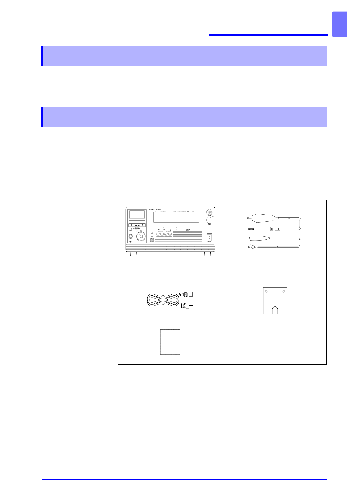
Confirming Package Contents
• When you receive the in strument, inspect it c arefully to ensu re that no damage occurred during shipping. In particular, check the accessories, panel
switches, and connec tor s. If d amage is evident, or if it fails to op er ate acc ording to the specifications, contact your dealer or Hioki representative.
• When transporting the in stru ment, u se the orig inal packing ma terials in wh ich
it was shipped, and pack in a double carto n. Damage oc curring during tr ansportation is not covered by warranty.
1
Introduction
Model 3174 (-01) AC Automatic Insulation/Withstanding HiTester
..........................................................1
Power Cord.......................................1 Slip Prevention Plate.........................1
Instructi on Manual.......................... 1
* The 3174-01 AC A utomatic Insul ation/ Withstan ding H iTester can be used with
GP-IB.
Options 9613 Remote Control Box (Single)
9614 Remote Control Box (Dual)
9615 H.V.Test Lead
9616 Warning Lamp
9267 Safety Test Data Management Software
9637 RS-232C Cable (1.8 m, 9-pin to 9-pin)
9638 RS-232C Cable (1.8 m, 9-pin to 25-pin)
9151-02 GP-IB Connector Cable (2 m)
9151-04 GP-IB Connector Cable (4 m)
Model 9615 H.V.Test Lead
.......................... (HIGH/ LOW, 1 each)
Page 8
2
Safety Information
Safety Information
This instrument is desi gned to comply with IEC 61010 Safety Standards,
and has been thoroughly tested for safe ty prior t o shipment. How ever, mishandling during use could result in injury or death, as well as damage to
the instrument. Using this instrument in ways other than those specified in
this manual may damage functions which guarantees the safety of this
instrument. Be certain that you understand the instructions and precautions in the manual before use. We disclaim any responsibility for accidents or injuries not resulting directly from instrument defects.
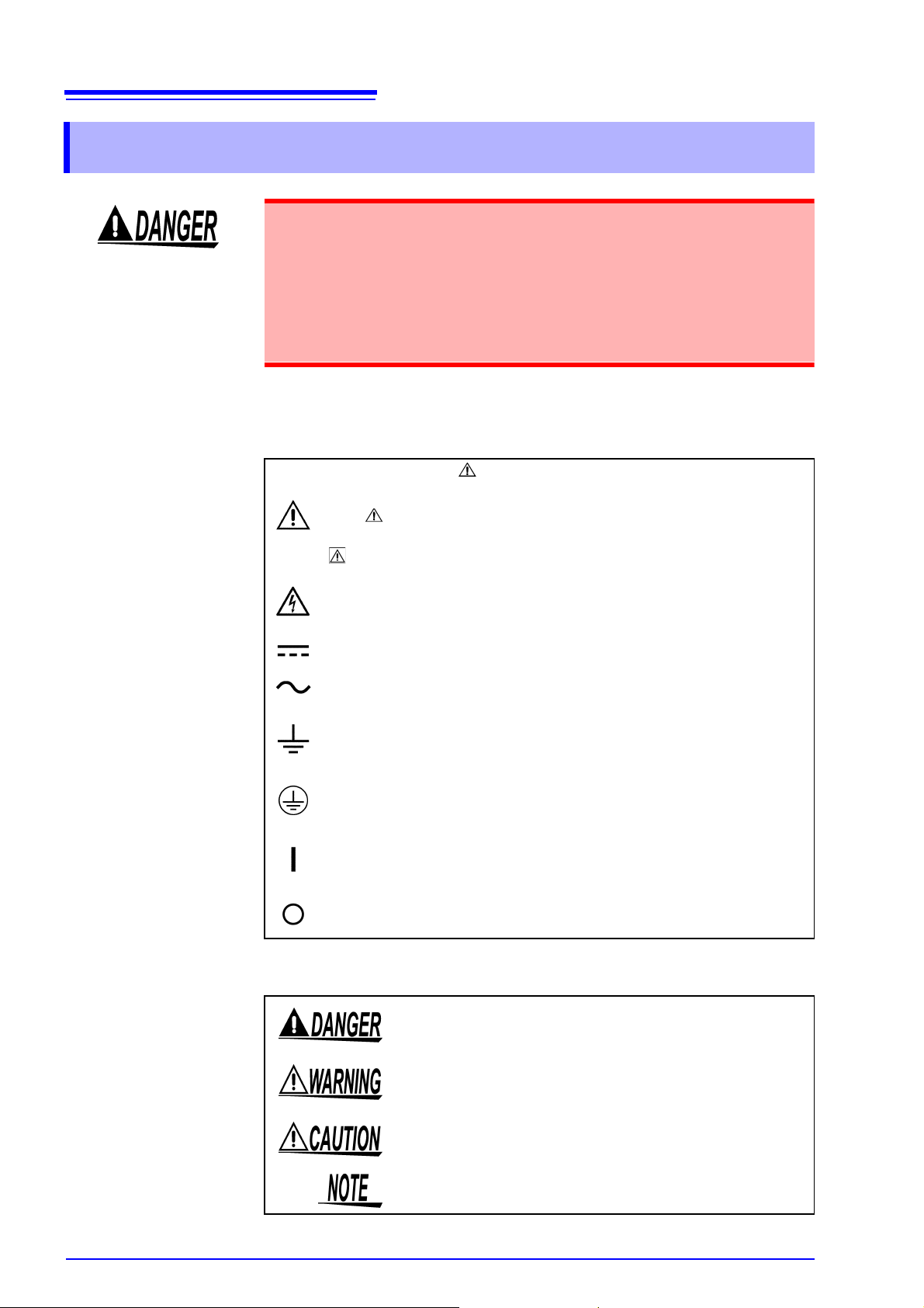
Safety Symbols
This manual contain s information and warnings essential for safe operation of
the instrument and for ma intainin g it in safe ope rating condi tion. Befo re using it,
be sure to carefully read the following safety precautions.
In the manual, the symbol indicates particularly important information that the user should read before using the instrument.
The symbol printed on the instrument indicates that the user
should refer to a cor responding topic in the manual (marked with the
symbol) before using the relevant function.
Indicates that dangerous voltage may be present at this terminal.
Indicates DC (Direct Current).
Indicates AC (Alternating Curre nt).
Indicates a grounding terminal.
Indicates a protective conductor terminal.
Indicates the ON side of the power switch.
Indicates the OFF side of the power switch.
The following symbols in this manual indicate the relative importance of cautions
and warnings.
Indicates that incorrect operati on pres en ts an extreme haz ard that could result in serious injury or death to the user.
Indicates that incorrect operation presents a significant
hazard that could result in serious injury or death to the
user.
Indicates that incorrect operation presents a possibility of
injury to the user or damage to the instrument.
Indicates advisory ite ms related to performance or corre ct
operation of the instrument.
Page 9
Other symbols
3
Safety Information
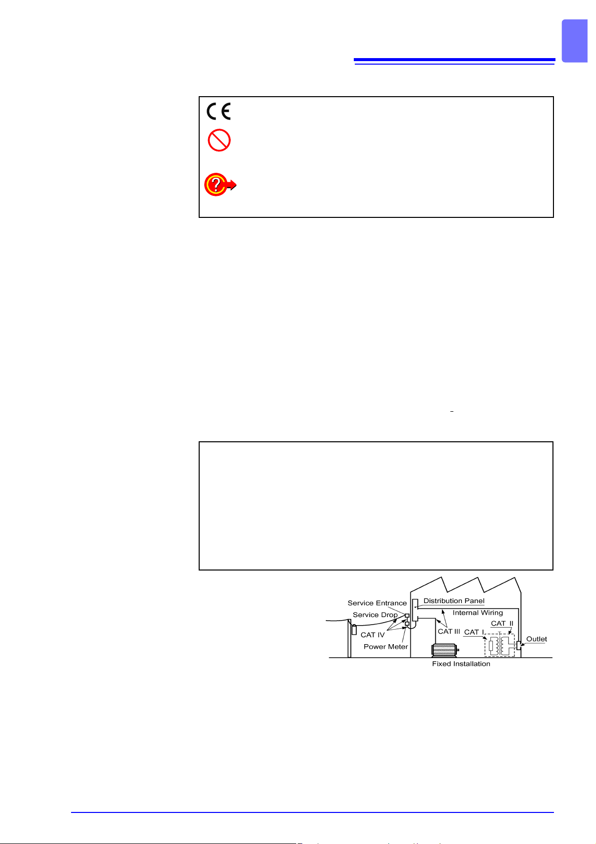
This symbol indicates that the product conforms to safety regulations
set out by the EC Directive.
Indicates a prohibited action.
( p. )
Indicates the location of reference information.
Indicates quick references for operation and remedies for trouble-
shooting.
*
Indicates that descriptive information is provided below.
Accuracy
We define measurement tolerances in terms of f.s. (full scale), rdg. (reading) and
dgt. (digit) values, with the following meanings:
f.s. (maximum display value or scale length)
The maximum d isplaya ble v alue o r scal e len gth. This is usually the na me of t he
currently selected range.
rdg. (reading or displayed value)
The value currently being measured and indicated on the measuring instrument.
dgt. (resolution)
The smallest dis playable unit on a digital measurin g instrument, i.e., the input
value that causes the digital display to show a "1" as the least-significant digit.
Measurement categories (Overvoltage categories)
This instrument complies with CAT I, CAT II safety requirements.
To ensure safe operation of measurement instrument, I
safety standards for various electrical environments, categorized as CAT I to
CAT IV, and called measurement categories. These are defined as follows.
CAT I:
CAT II:
CAT III:
CAT IV:
Secondary electrical circuits connected to an AC electrical outlet
through a transformer or similar instrument.
Primary electrica l circui ts in equip men t connec ted to an AC ele ctr ica l
outlet by a power cord (portable tools, household appliances, etc.)
Primary electrical circuits of heavy equipment (fixed installations)
connected directly to the distribution panel, and feeders from the distribution panel to outlets.
The circuit from the se rvice drop to the servi ce entrance, and to the
power meter and primar y overcu rrent pr otection in strum ent (di stribution panel).
EC 61010 establishes
Higher-numbered categories correspond to electrical environments with
greater momentary
energy. So a measurement
instrument designed for
CAT III environments can
endure greater momentary energy than a instrument designed for CAT II.
Using a measurement instrume nt in an environment designated with a hi ghernumbered category than that for which the instrument is rated c ould result in a
severe accident, and must be carefully avoided.
Never use a CAT I measuring instrument in CAT II, III, or IV environments.
The measurement categories comply with the Overvoltage Categories of the
IEC60664 Standards.
Page 10
4
Operating Precautions
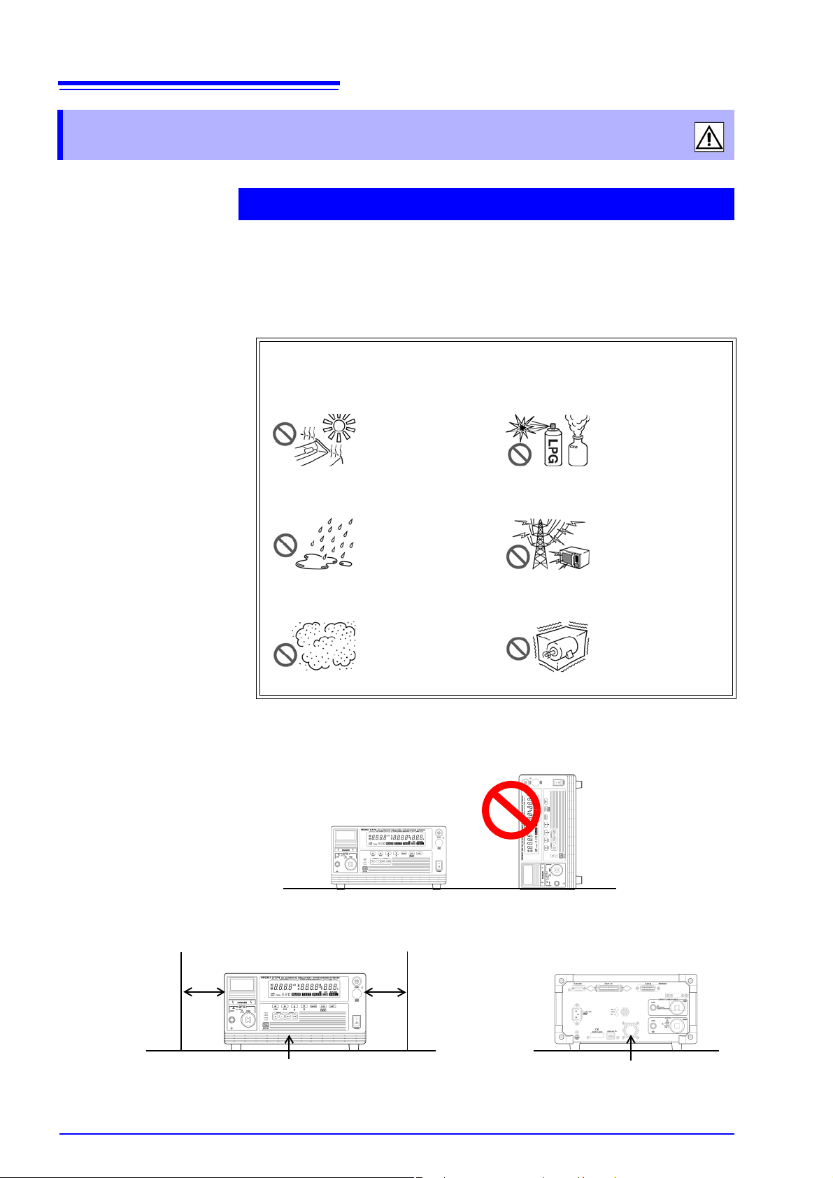
Operating Precautions
Instrument Installation
Operating temperature and humidity:
Temperature and humidity range for guaranteed accuracy:
Avoid the following locations that could cause an accident or damage
to the instrument.
0 to 40°C at 80% RH or less (no condensation)
23±5°C, 80%RH or less (no condensation)
after 10 minutes minimum warm-up
Installation
Exposed to direct sunlight
Exposed to high temperature
Exposed to liquids
Exposed to high humidity or condensation
Exposed to high levels of particulate dust
• The instrument should be operated only with the bottom side downwards.
In the presence of corrosive or explosive
gases
Exposed to strong
electromagnetic fields
Near electromagnetic
radiators
Subject to vibration
Spacing of more
than 10 cm
• Vents must not be obstructed.
Spacing of more
than 10 cm
Ventilation holes
Ventilation holes
Page 11
5
Operating Precautions
Before Use
Before using the instrument the first time, verify that it operates normally to
ensure that the no damage oc curred during sto rage or shipping. If y ou find any
damage, contact your dealer or Hioki representative.
Before using the instrument, make sure that the insulation on the test
leads is undamaged and that no bare conductors are improperly exposed.
Using the instrument in su ch c o ndi tions co uld cause an elec tric sh ock, so
contact your dealer or Hioki representative for repl acements. (Model 9615
H.V.Test Lead)
Handling the Instrument
• To avoid electric shock, do not remove the instrument's case. The inter-
nal components of the instrument carry high voltages and may become
very hot during operation.
• To avoid damage to the instrument, protect it from physical shock when
transporting and handling. Be especially careful to avoid physical shock
from dropping.
Handling the test leads
• For safety reasons, when taking mea surements, only use the 9615 H.V. Test
Lead provided with the instrument.
• To avoid breaking the test leads, do not bend or pull them.
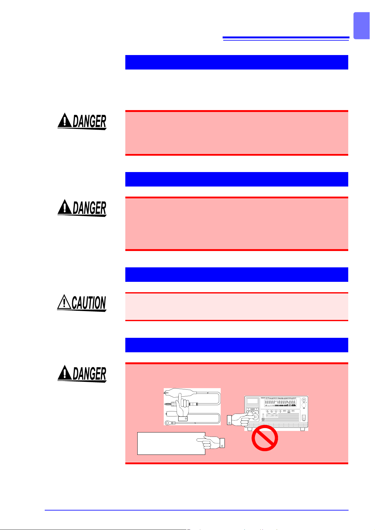
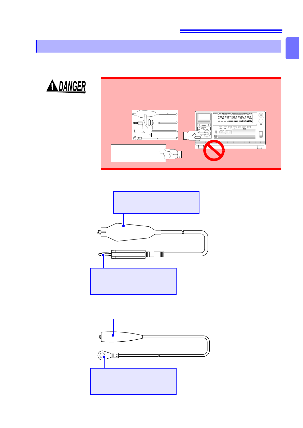
Safety Precautions during Testing
To prevent electric sho ck, whe n the DANGER lamp is lit or during the test,
never touch the voltage output terminals, test lead, or the tested object.
Tested object
Page 12

6
Operating Precautions
Page 13
1.1 Product Overview
Overview Chapter 1
1.1 Product Overview
Inaccuracies i n measurements ha ve been noted to occur during th e withstandvoltage and insulatio n-resistance tests bec ause of variations in the tes t voltage
caused by fluctuations in the voltage supply, breaking of the test leads and
improper connection.
Model 3174, 3174-01 AC Automatic Insulation/Withstanding HiTester is an
affordable insu lation/withstanding testing instrument equipped with stab le voltage supply and c ontact check fu nction s t o preven t a decr ease in te stin g reliab ility caused by these factors.
In addition, to improve the efficiency of the testing process on the production
line, it allows testing setti ngs to be retrieve d from b oth RS-232 C (GP-IB) as well
as EXT I/O.
7
1
Front Panel Rear Panel
1.2 Features
Carry out standards-based tests with simple operations
Once test conditions have been pre-set beforehand, withstanding and insulationresistance tests w hich meet indu strial st andards ca n be carried out with just the
simple push of a button. Functions such as PASS-FAIL evaluation based on
upper-limit and lower-limit test values, testing time timer, ramp-up/ramp-down
time timer to control voltage fluctuations ensure accurate test results are
obtained.
Saving and loa ding test conditions
Once test conditi ons required for th e various ind ustrial standards and device to
be tested have been saved, tests can be carried out smoothly by just switching
to the required te st conditions. Up to 8 conditions can be saved for the withstanding and insu lation-re sistance te sts respec tively. In a ddition, tes t conditi ons
for the last test are automatically retrieved when the power is switched on.
Page 14
8
1.2 Features
Automatically carry out consecutive withstanding and insulationresistance tests
Withstanding and insulation-resistance tests can be carried out consecutively
when the respective test conditions have been pre-set. Pressing the W→I key
will automaticall y run th e withstand ing test f ollowed by the insu lation-resi stance
test, pressing the I→W key will automatically run the insulation-resistance test
followed by the withstanding test.
Contact check function to increase testing reliability
With the contact chec k functi on, the re lia bility o f tests carried o ut impr oves wi thout the need to incr ease t esting ti me (Ano ther s et of t he 9615 H.V. Tes t Lead is
necessary)
Real execution value shown
By showing t h e r e al ex ec u ti o n v al u e, te st s f a ith f ul t o in dustrial s t an d ar ds ar e carried out.
Cutting out influence from supply voltage fluctuations
By using PWM switching power supply, the desired voltage supply can be set so
even if the supply voltage flu ctuates within ±10% of the preset value, the test
voltage will not be affected. This improves the reliability of the test results.
Continuation of testing even after test failure makes analysis of
sample possible (Test Continuation status)
Under normal conditions, testing immediately stops when the test fails, making it
impossible to determine whether the cause is because of a short circuit or a
value exceeding the thresho ld value. The Test Continuation Status allows the
test to continue even after a FAIL r esult is obtained, thus making it possi ble to
analyze the problem.
EXT I/O in standard package
This instrument is equipped with EX T I/O as a standa rd package. This enab les
signal transmissions fro m E XT I/O, start and stop controls of tes ts an d retr i evals
of saved test conditions.
RS-232C (Standard Package)/GP -IB Interface (Standard Package
for 3174-01 only)
This instrument is equipped with RS-232C as a standard package and the 317401 is also equipped with GP -IB as a sta ndard package. By connecting to a computer, they allow for auto testing to be carried out and test results to be read.
Easy-to-see big screen
Big-sized fluo rescent dis play tubes are use d for the disp lay, allow ing te st c onditions and test results to be confirmed easily.
Remote Control Box for safer test administrations (optional)
When the optional Rem ote Co ntrol Box is conne cted to the instrument, test start
or test stop functions ca n be performed without touching the instrument, thus
making test adm inistr ations s afer. The 961 3 R emote C ontrol B ox ( Single) , 961 4
Remote Control Box (Dual) are available.
Page 15

9
1.3 Names and Functions of Parts
1.3 Names and Functions of Parts
1.3.1 3174 (3174-01)
Explanations on names and parts of instrument.
Front Panel
DANGER lamp
Light blinks to warn of voltage supply.
To prevent electric shock, when the
DANGER lamp is lit, never touch
the voltage output terminals, test
lead, or the tested object.
Display
(p. 12)
Please carry out the test regularly on th e instrument
by following the test procedures in "2.6 Pre-test
Check" (p. 26).
See "6.1.3 Double Action" (p. 81)
START Key
Start a test.
(Functions only when the lamp is lit.)
STOP Key
Terminate a test.
Operation Keys
(p. 10)
1
Connection terminal for
remote control
Connect the remote control box (optional)
HIGH Voltage output terminal
The HIGH terminal is a high-voltage terminal for voltage outputs.
LOW Voltage output terminal
The LOW terminal is a low-voltage terminal for voltage outputs.
It has the same electric potential
as the unit body.
POWER Switch
Turns the instrument on and off.
: Power on
: Power off
(The diagram shows a 3174 AC Automatic Insulation/Withstanding
HiTester.)
Page 16
10
1.3 Names and Functions of Parts
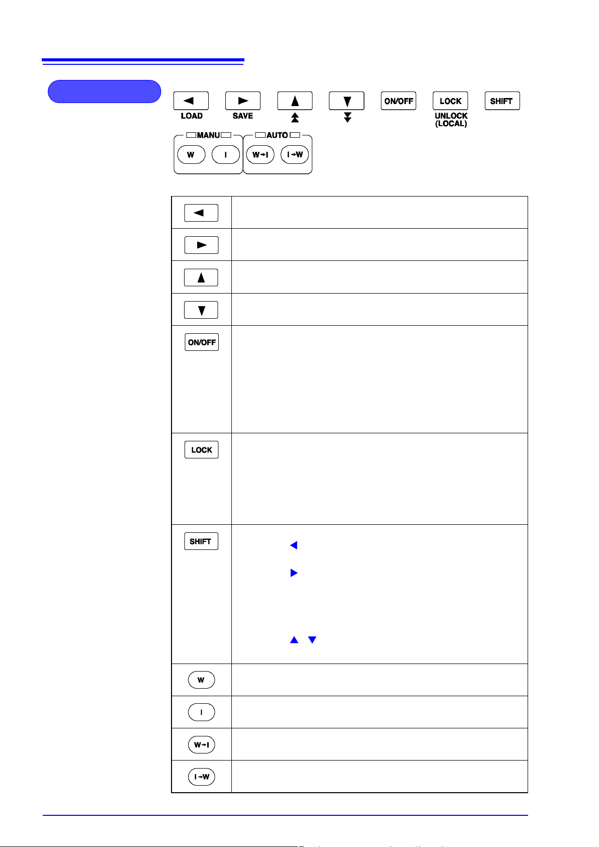
Operation Keys
Moves the flashing cursor to the left.
Moves the flashing cursor to the right.
Raise the selected value with the flashing cursor.
Lower the selected value with the flashing cursor.
UNLOCK
(LOCAL)
Change the ON/OFF for the selected setting with the flashin g
cursor. If turned off, the set value is not used in testing.
• The following item can't perform the switching on/off:
Withstand-voltage test:
Test-voltage value, Test-voltage frequency, Upper-limit test
value
Insulation-resistance test:
Test-voltage value, Lower-limit test value
Used to lock the keys.
Only the following keys are available during Key Lock. (p. 79)
UNLOCK key (LOCK + SHIFT key)
START key
STOP key
• In the remote state, this key functions as a LOCAL key.
It cancels the remote state.
Used in combination with other keys.
• SHIFT + key
Displaying the loading screen.(p. 102)
• SHIFT + key
Displaying the saving screen.(p. 99)
• SHIFT + LOCK key
Cancels the key lock.
When GP-IB is used for communication, go to LOCAL state.
• SHIFT + / key
Changing the increment size of setting values.
Performs withstand-voltage tests and settings.
"Chapter 3 Withstand- Voltage Test" (p. 29)
Performs insulation-resistance tests and settings.
"Chapter 4 Insulation- Resistance Test" (p. 47)
Tests for withstand-voltage, then insulation-resistance.
"Chapter 5 Automatic Test" (p. 69)
Tests for insulation-resistance, then withstand-voltage.
"Chapter 5 Automatic Test" (p. 69)
Page 17
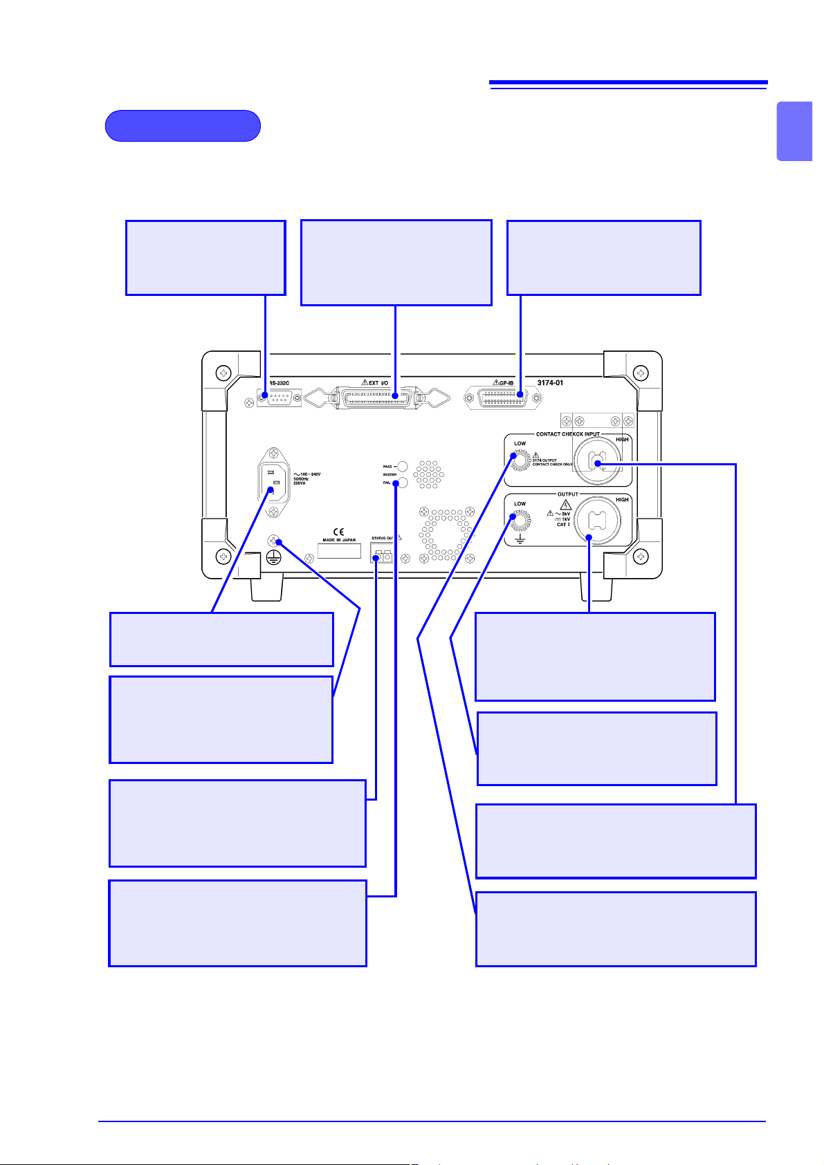
Rear Panel
11
1.3 Names and Functions of Parts
1
RS-232C connector
Used for remote control with RS-232C.
Power Inlet
Connect the supplied power cord
here
Protective conductor terminal
Used to earth a protective
ground wire. Be sure to make
grounding connections before
starting a test.
Status Out Relay Terminal
When conditions pre-set in the Status
Out setting are met, the relay connection gets switched ON.
EXT I/O connector
For output of 3174 state
and input of start and stop
signals.
GP-IB connector (3174-01)
Used for remote con trol with
GP-IB.
HIGH voltage output terminal
A high-voltage terminal for voltage output. Connected to the
HIGH terminal on the front panel.
LOW voltage output terminal
A low-voltage terminal for voltage
output. Contains the sa me electrical
potential as this units casing.
HIGH contact check terminal
A high-voltage terminal for c ontact check.
Use the Slip Prevention Plate.
Buzzer adjustment knob
Used for buzzer sound adjustment.
Two knobs are prov ided: one for PASS
screening and one for FAIL screening.
The diagram shows a 3174- 01 (wi th GP- IB) AC A utomati c Ins ulatio n/With standing HiTester.
LOW contact check terminal
A low-voltage terminal for contact check.
Page 18
12
.
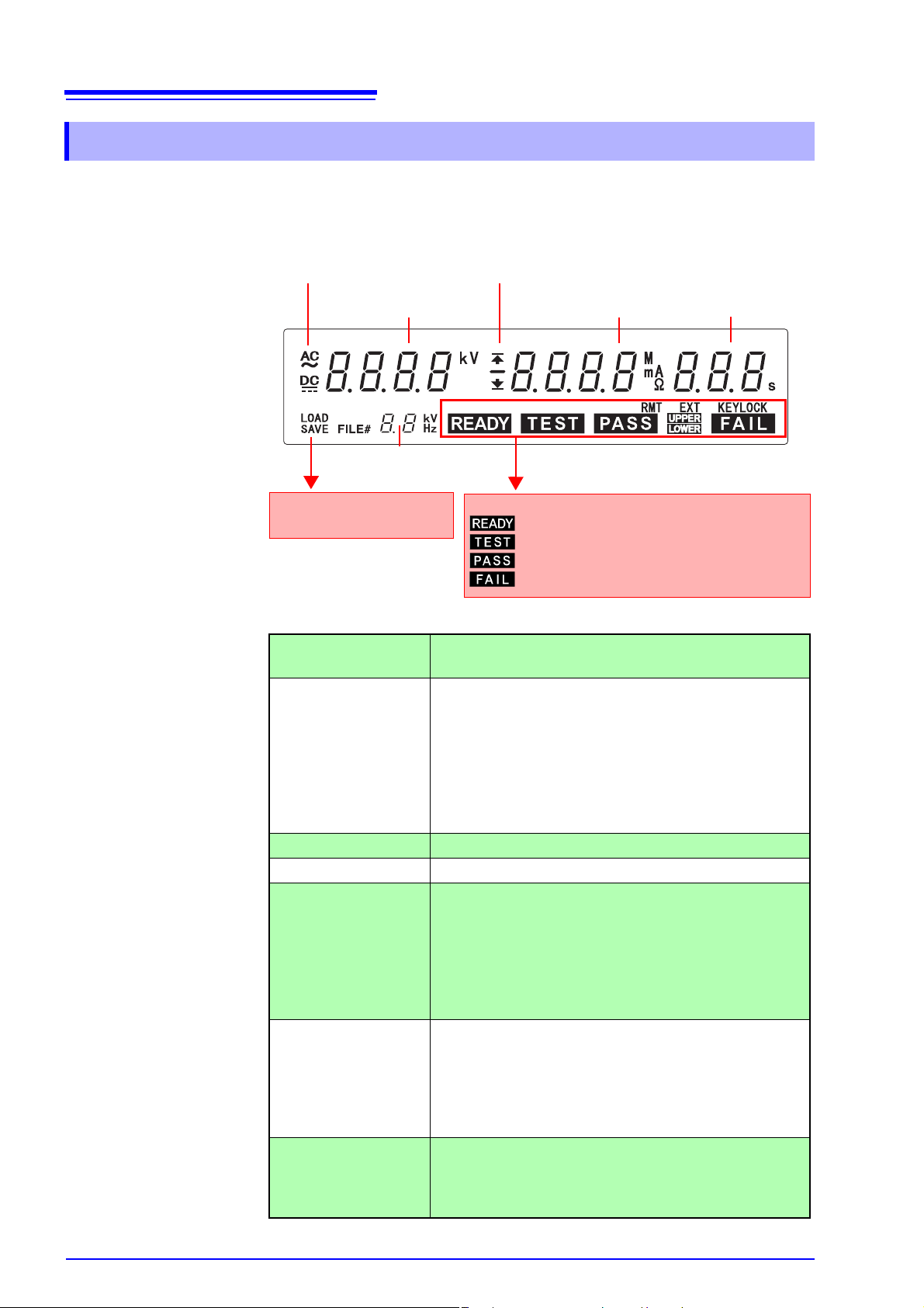
1.3 Names and Functions of Parts
1.3.2 Display
Test setting conditions and current status of the instrument are shown in the
panel on front of the instrument.
Test type
Test-voltage value
Test-frequency
Initial voltage for ramp-up
SAVE: Saving screen
LOAD: Loading screen
Test type
Test-voltage value
Upper-limit value icon Lights up when indicating the upper-limit test value.
Lower-limit value icon Lights up when indicating the lower-limit test value.
Upper-limit test value
Lower-limit test value
Test time
Ramp-up time
Ramp-down time
Delay time
Test-frequency
Initial voltage for
ramp-up
Upper-limit value icon
Lower-limit value icon
Upper-limit test value
Lower-limit test value
Indicates the current condition of the instrument
: The instrument is ready for starting a test
: The instrument is in the TEST state.
: The tested object passed the test.
: The tested object failed to pass the test.
“AC” lights up during withstanding testing.
“DC” lights up during insulation-resistance testing.
During testing and READY:
Monitors and indicates the voltage of the output terminal.
During voltage setting:
Indicates the ea ch item set. (output voltage, Con -
tact Check upper (lower)-limit voltage)
Reverse current cannot b e detected bec ause monitor
shows voltage and residual voltage.
Indicates the upper-limit test value when the upperlimit value icon lights up and indicate s the lower-limit
test value when the lower-limit value icon lights up.
Also indicates the Contact Che ck upper-limit voltage
when [Hi] is shown in Test Frequency and Initial
Ramp-up Voltage, and indicates the Contact Check
lower-limit voltage with [Lo].
Indicates testing time.
Indicates the ramp-up time when [UP] is shown in T est
Frequency and Initi al Ramp -up Voltage, and indicates
the ramp-down time together with [dn].
Indicates the delay time together with [dL] during insulation-resistance testing.
Indicates Test Frequency (50 Hz/60 H z) when [Hz] is
shown. Indicates the Initial Voltage (proportion to Testing Voltage) when Ramp-up Timer is being used
within the range of 0 to 1.0.
Test time
Ramp-up time
Ramp-down time
Delay time
Page 19
13
1.3 Names and Functions of Parts
1.3.3 Model 96 15 H.V.Te st Lead
Explanations on names and parts of Test Lead.
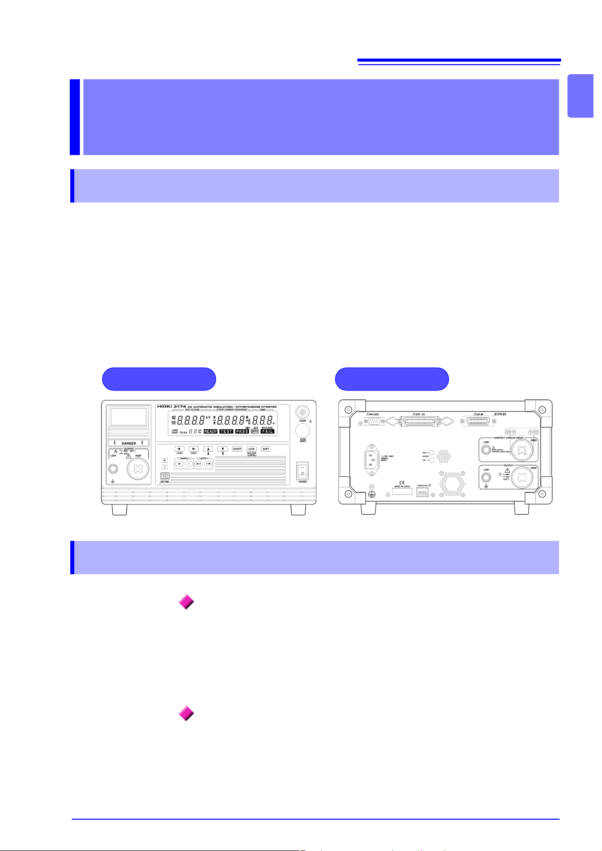
To prevent electric sho ck, whe n the DANGER lamp is lit or during the test,
never touch the voltage output terminals, test lead, or the tested object.
There is no insulation/withstand-voltage on the Alligator clip vinyl covering.
Tested object
9615 H.V.Test Lead
1
Alligator Clip
Connect to a test point on the tested object.
High-voltage output plug
Connect to the HIGH voltage output
terminal on the instrument.
Alligator Clip
Low-voltage output plug
Connect to the LOW voltage output
terminal on the instrument.
Page 20
14
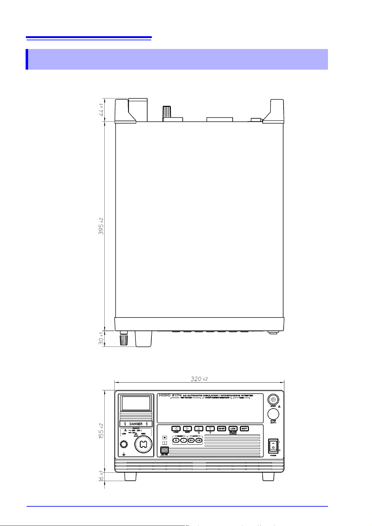
1.4 External Dimensions
1.4 External Dimensions
Model 3174, 3174-01 AC Automatic Insulation/Withstanding HiTester
Page 21
15
1.5 Testing Process
1.5 Testin g Proc e ss
Explanation of the basic flow of withstanding and insulation-resistance tests.
Testing Arrangements
(p. 17)
1. Connect the protective conductor terminal.
2. Connect the power cord.
3. Connect the test lead. (Voltage output terminal, Contact check terminal)
4. T u rn on the power.
5. Carry out pre-test check.
2
1
1
4
ON
3
Tested object
Withstand-voltage test (p. 29) Insulation-resistance test (p. 47)
Select the test type Press the W key. Press the I key.
Set test conditions 1. Set the test voltage value.
(p. 32)
2. Set the upper (lower) limit value.
(p. 33)
3. S et the tes t time timer .
(p. 34)
4. Set the ramp-up (ramp-down)
timer. (p. 35)
5. S et the tes t- freque nc y. (p. 36)
6. Set the Initial voltage for ramp-up.
(p. 37)
Set the upper-limit voltage and lower-limit voltage for Contact Check, if necessary.
(p. 38) (p. 55)
1. Set the test voltage value.
(p. 50)
2. Set the upper (lower) limit value.
(p. 51)
3. Set the test time timer.
(p. 53)
4. Set the delay time. (p. 54)
Executing a test Press the START key. (p. 40 ) Press th e START key. (p. 57)
Displaying the test result
or is displayed.
(p. 44)
or is displayed.
(p. 61)
Page 22

16
1.5 Testing Process
Page 23
Testing
17
2.1 Arrangements Work Flow
Arrangements Chapter 2
2.1 Arrangements Work Flow
Getting ready to start the test.
2
1
3
2
4
ON
Tested object
1
2
3
4
5
To carry out a safer test
• The Remote Control Box to start or stop the test can be used.
"Appendix1 Remote Control Box" (p. A1)
•
The instrument can be controlled with EXT I/O, RS-232C or GP-IB (only
for 3174-01).
"Chapter 8 External Interface" (p. 103)
"Chapter 9 RS-232C/GP-IB Interface" (p. 121)
"Connecting the Protective Conductor Terminal" (p. 18)
"Connecting the Power Cord" (p. 19)
"Connecting the Test Lead" (p. 20)
"Turning the Power On and Off" (p. 24)
"Pre-test Check" (p. 26)
<Ex.>
Without Contact Check
Page 24
18
Rear panel
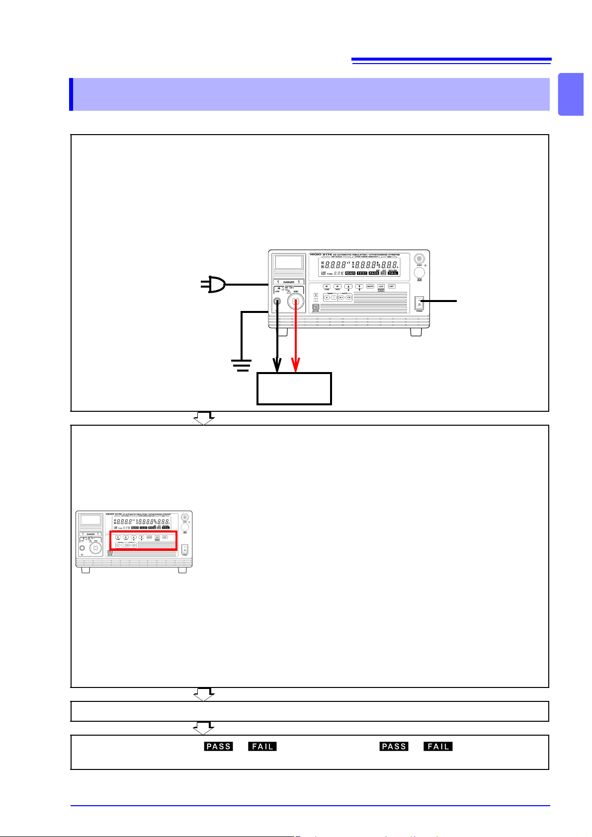
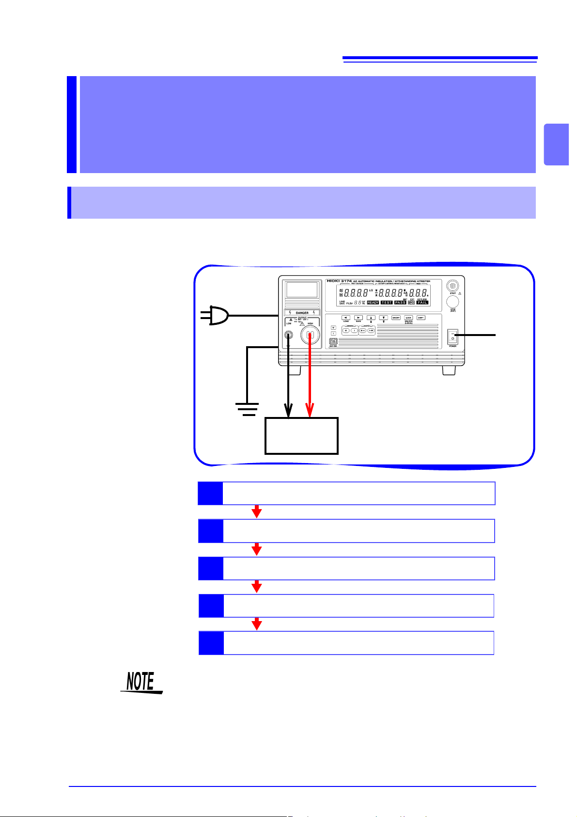
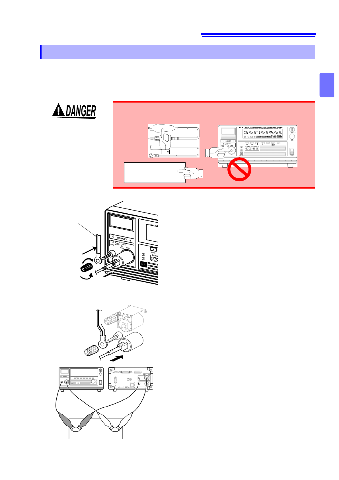
2.2 Connecting the Protective Conductor Terminal
2.2 Connecting the Protective Conductor Terminal
To carry out the test safel y, connect the protectiv e conductor termin al found on
the back of the instrument to earth.
If the ground-type dou ble- pole po wer cord that is suppl ied with th e inst rumen t is
used, the instrument is automatically grounded.
T o avoid electric shock, observe the following.
• Connect the protective conductor terminal to earth (earth ground) before
making any other connections.
• Be sure to connect the protective conductor to earth (earth ground).
Connect to
earth
Prepare:
Phillips-head screwdriver,
Earth wire or cable
1. Make sure that the power switch is turned
off.
2. Using a Phillips-head screwdriver, remove
the protective conductor terminal from the
rear of the instrument.
3. Connect an electric wire with a sufficient
current capacity to the protective conductor terminal.
(
A wire with a diameter of more than
2
1.25mm
is recommended.)
4. Secure the wire using a Phillips-head
screwdriver.
5. Ground the other end of the wire or cable.
Protective conductor terminal
Page 25
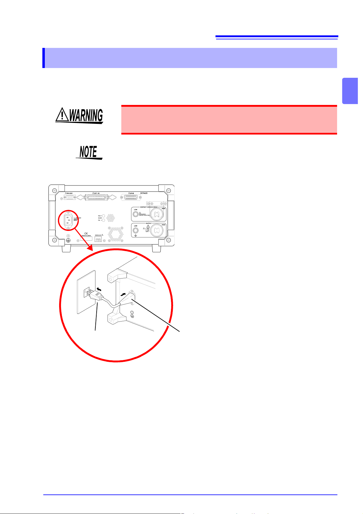
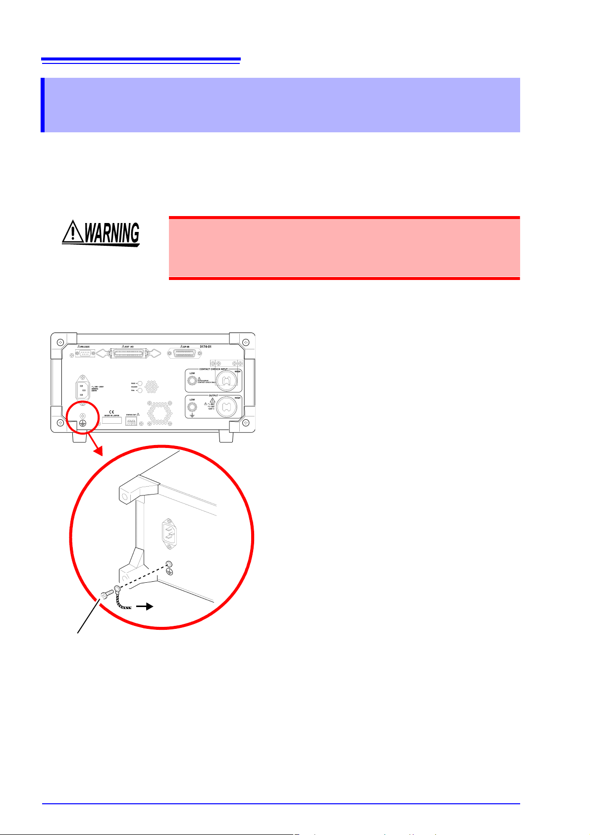
2.3 Connecting the Power Cord
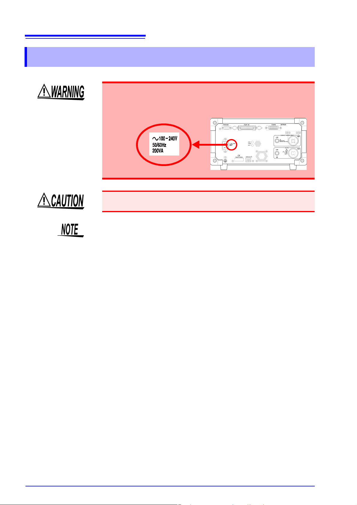
Connect the power cor d to the p owe r inl et on the b ack o f the ins trument and the
plug to the wall socket to provide power to the instrument.
To avoid electrical accid ents and to maintain the safety specificati ons of
this instrument, connect the power cord only to a 3-conta ct (two-conduc tor
+ ground) outlet.
Make sure the po wer i s turned off befo re c onn ectin g or disconnecting the power
cord.
Rear panel
1. Make sure that the power switch is turned
off.
19
2.3 Connecting the Power Cord
2
Plug
2. Connect the power cord provided to the
power inlet on the back of the instrument.
3. Insert the plug into the grounded outlet.
Power inlet
Page 26
20
2.4 Connecting the Test Lead
2.4 Connecting the Test Lead
Connect the 9615 H.V. Test Le ad to the Vo ltage O utput T erminal on the fron t of
the instrument. When using Contact Ch eck, connect to th e Contact Check Te rminal on the back as well.
• Before using the instrument, make sure that the insulation on the test
leads is undamaged and that no bare conductors are improperly
exposed. Using the instrument in such conditions could cause an electric shock, so contact your dealer or Hioki representative for replacements. (Model 9615 H.V.TEST LEAD)
• To avoid shock and short circuits, turn off power before connecting test
leads.
• To avoid electric shock, make sure the test lead is secur ely connected
before starting a test, as a loose test lead can cause a hazard when a
voltage is output.
• Never touch the voltage output term inals, test lead, or th e tested object
during a test (when is light up).
• Voltage may still remain on the voltage output terminal even after the test
has completed. Confirm that no more voltage is left on the voltage output
terminal when touching the voltage output terminals, test lead, or the
tested object.
• To av oid ele ctric sho ck, mak e su re t he power is switched off befor e co nnecting a ferrite or resistor to remove noise.
• Inaccuracy in meas urement m ay occu r during insulati on-resistance test if the
instrument is put in a humi d plac e so try t o avoid d oin g so. If th ere i s a poss ibility of the test lead becoming too humid, protecting the test lead with desiccant is recommended. If the test lead touches other metals, leakages in
electric current may i ncreas e so be ca reful when coi ling the test lea d to avoid
touching other parts.
• Do not allow the test l ead used for Contact Check (HIGH, LOW terminal s) to
directly touch the test lead for the voltage output terminals (HIGH, LOW terminals) as this may make detecting loose conn ection difficult.
• If the HIGH and LOW voltage output terminals short-circuit or a dielectric
breakdown occurs in the tested object during the test, noise will be generated
and such noise m ay lead to a malfunction of this instrument or o f a nearby
electronic device . If t his p robl em oc cu rs , connect a ferrite core or a r es istor to
the H. V. Test Lead (high voltage side). When using a r esistor, choose one
appropriate for the power rating and withstand voltage. Also, b e alert to any
drop in test voltage.
Page 27
2.4 Connecting the Test Lead
1.
y
n
y
h
r-
e
e
e
ill
e
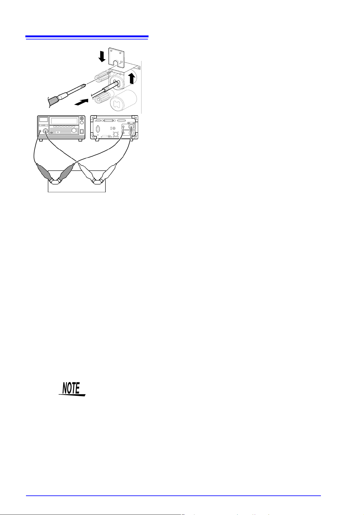
2.4.1 When using the Contact Check Function
When using the Contact Check Function, connect the test lead as follows.
On the usage of Contact Check,
ting the Confirmation Voltage used for upper and lower-limits for Contact Check".
To prevent electric sho ck, whe n the DANGER lamp is lit or during the test,
never touch the voltage output terminals, test lead, or the tested object.
Tested object
see "2.6 Pre-test Check" "3 .1.7" "4.1.5 S et-
21
2
When the front terminal is used
The H.V. Test Lead
(low voltage side)
2
3
4
1
When the back terminal is used
5
Remove the LOW voltage output terminal b
turning it counterclockwise.
2. As shown in the left figure, insert the plug o
the H.V. Test Lead (low voltage side).
3. Secure the LOW voltage output terminal b
turning it clockwise.
4. Connect the plug on the H.V. Test Lead (hig
voltage side) to the HIGH voltage output te
minal.
5. Connect in the same way when using th
voltage output terminals on the back of th
instrument as well.
6
7
Tested object
6. Connect the test lead of the LOW voltag
output terminal to the tested object.
Ensure the connection is secure so that it w
not come off during the test.
7. Connect the test lead of the HIGH voltag
output terminal to the tested object as well.
Page 28
22
8.
i-
st
ct
ct
h
i-
ill
ct
s
-
2.4 Connecting the Test Lead
11
Tested object
Contact check function
By measuring the t erminal voltage of th e tested object, it i s possible to confir m
whether a test voltage is supplied to the tested object or not (Contact check function).
To use the Contact check function, besides the test output terminal, a set of
9615 H.V. Test Lead for test is necessary. (optional)
For this instrument, th e voltage detected by the Contact ch eck terminal will be
differentiated from the test voltage and referred to as the contact voltage.
When the Contact voltage is smaller than the pre- set lowe r-lim it voltage fo r contact check, broken wire or poor connection is suspe cted and a contact error wil l
be displayed (Refer to "3.1 .7", "4.1.5 Setting the Confirmation Volta ge used for
upper and lower-limits for Con tac t Che ck", "11 .3 Err or Indi c ati on" for erro rs) . By
setting an upper-lim it voltage for Contact check, d etection for any abnormality
(supply of voltage higher than the pre-set value) in the output voltage is possible.
When the Contact check terminal is conn ected to the test ed object, ens ure that
the test lead for the Contact check do es not directly touch the test lea d for the
test as shown in the di agram (ensure that the test lead for the C ontact check
touches the test lead for the test through the terminal for the tested object).
If the test lead for the Cont act ch eck d irectl y touches the tes t lead for the te st, a
broken wire will be detected but a supply of test voltage to the tested object cannot be confirmed.
• When the contact chec k terminal on the LOW side is connected not to the
• A voltage of approximately DC15 V runs thr ough the contact chec k term inals.
Remove the slip protection plate of the term
nals for Contact Check and connect the te
leads in the same way as steps 2 to 4.
9
8
10
9. Connect the test lead of the LOW Conta
Check terminal to the tested object.
Make sure the probe on the LOW Conta
Check terminal side does not directly touc
the probe on the LOW Voltage Output Term
nal side during this process.
Ensure the connection is secure so that it w
not come off during the test.
10. Connect the probe on the HIGH Conta
Check terminal side to the tested object a
well.
11. Put back the slip protection plate after con
nection.
tested object but to GND , an accurate contact check cannot be carried out.
Ensure that the contact c heck terminal on the LOW side does not touch th e
GND even when it is removed.
During insulation-resistance measurements, when the LOW Contact Check
terminal is connected to the HIGH measurement terminal, a voltage of approximately 15 V will be indicated however this is not a malfunction.
Page 29
2.4 Connecting the Test Lead
When the front terminal is used
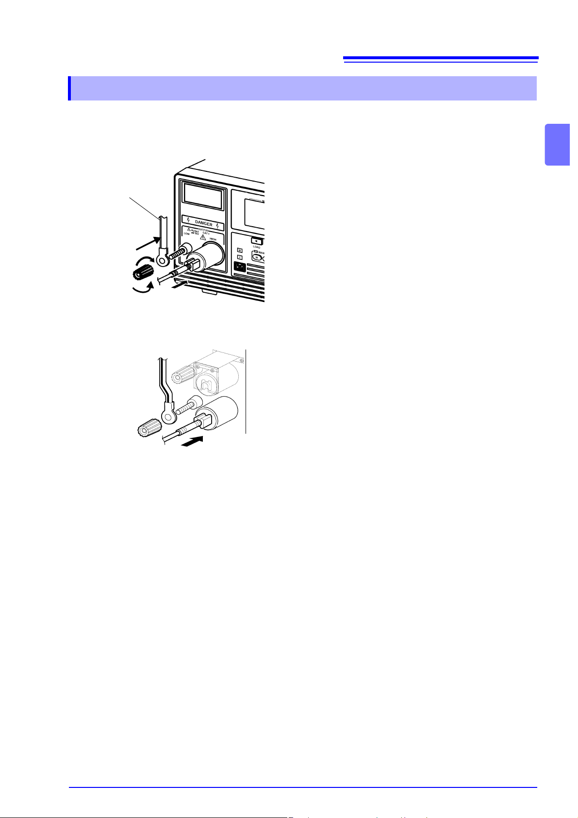
2.4.2 When not using the Contact Check Function
When not using the Contact Check Function, connect the test lead as follows.
23
2
The H.V. Test Lead
(low voltage side)
2
3
1
When the back terminal is used
5
4
1. Remove the LOW voltage output terminal
by turning it counterclockwise.
2. As shown in the left figure, insert the plug
on the H.V. Test Lead (low voltage side).
3. Secure the LOW voltage output terminal
by turning it clockwise.
4. Connect the plug on the H.V. Test Lead
(high voltage side) to the HIGH voltage
output terminal.
5. Connect in the same way when using the
voltage output terminal s on the back of the
instrument as well.
6. Connect the test lead of the LOW voltage
output terminal to the tested object.
Ensure the connection is secure so that it
will not come off during the test.
7. Connect the test lead of the HIGH voltage
output terminal to the tested object as
well.
Page 30
24
2.5 Turning the Power On and Off
2.5 Turning the Power On and Off
Before turning the instrument on, make sure the supply voltage matches
that indicated on the its power connector. Connection to an improper supply voltage may damage the instrument and present an electrical hazard.
To avoid dam aging the power cord, grasp the plug, not the cord, when unpl ugging it from the power outlet.
• Allow 10 minutes warming up after powering on.
The Remote Control Box, extern al I/O device, RS- 232C interface, and GP-IB
interface are active only when they are connected prior to startup. If these
devices are connected after the power is turne d on, thus causing a malfunction.
• After the power has been switched off, wait for about 5 minutes before turning
on the power again.
Page 31

Turning Power On
Front panel
25
2.5 Turning the Power On and Off
1. Turn the power switch to on ( ).
2. The “3174” (model name) and software
version are displayed on the screen.
Model name
Software version
(This diagram shows version 1.00.)
State of interface
"rS.0": RS-232C 9600 bps
"rS.1": RS-232C 19200 bps
"G.XX": GP-IB address XX
3. When the lamp is lit (it does not
light up in the Double Action mode), the
keys are ready for operation.
Action" (p. 81)
"6.1.3 Double
2
Turning Power Off
Front panel
1. For safety reasons, check the following.
• Test has completed
•The DANGER lamp is off.
• The lamp is lit.
2. Turn the power switch to off ( ).
Page 32

26
2.6 Pre-test Check
2.6 Pre-test Check
For safety reasons, check the following before starting test.
START key, STOP key
For safety reasons, switch off the power and pull the electric plug from the
socket before carrying out the check.
1. Press the center of the START key and STOP key in the front panel slowly with
your finger to confirm the feel of the key clicking. Pressing the side of the key will
make it difficult to feel the click.
(The feel of the c lick will be easier to unders tand when y ou press the key a f ew
times or compare it with the STOP key.)
* Feel of the click
When you press the key slowly, you will feel an initial resistance which seems to
be preventing the key from going down further. Press the key harder and you will
feel the clicking of the key.
Breaking current
2. The key is working properly if you feel the click.
3. The key may be damaged if you do not feel the click.
Contact your dealer or Hioki representative.
Before starting the withstanding test, check whether electric current has been
shut out when the pre-set voltage is outputted.
Recommended Insulation: High voltage-high insulat ion flat chip resist ors
GS series (from KOA Corporation) or similar
products
Note the usage voltage and power.
1. Prepare a resistor with a resistance smaller than that of the calculation result
from the test-voltage value and tes t upper- limit tes t value (breaki ng curr ent) that
are preset in the withstand -voltage test. When selecting the resistance, ensure
that the maximum volta ge usage is higher than the test voltage and the rate d
power is higher than the value which is calculated from the test voltage and
resistance values.
(Test-voltage)
(Test-voltage) < Maximum usage voltage of pre-set resistance
Square of test-voltage
÷ (Breaking current) > Resistance
÷ Resistance < Rated power of pre-set resistance
2. Set an upper-limit test value.
3. Connect the resistor that you prepared to the test lead.
4. Start the test. Confirm that the current is cut off whe n the preset voltage is out-
put. (i.e., make sure the instrument is in the FAIL state).
Page 33

Measured resistance
1. Prepare a resista nce with a val ue which is hig her than t he lo wer-limit te st val ue
2. Set a test voltage.
3. Connect the resistor that you prepared to the test lead.
27
2.6 Pre-test Check
Before starting the in sulat ion-res ista nce test , chec k th at the resi stance va lue for
measurement is the same as the pre-set value.
Recommended Insula tion: High voltage-high insulation flat chip resistors
GS series (from KOA Corporation) or similar
products
Note the usage voltage and power.
but close to it. W hen selec ting the re sist ance, ens ure that th e max imum volta ge
usage is higher than the test voltage and the rated power is higher than the value
which is calculated from the test voltage and resistance values.
(Test-voltage) < Maximum usage voltage of pre-set resistance
Square of test-voltage
÷ Resistance < Rated power of pre-set resistance
2
4. Make sure that the resistance measured matches the resistor that you prepared.
Inter-lock
If the Inter-lock fun ction is set, m ake sure the Inter-lock functi on works proper ly
before starting test.
See "8.3 Inter-lock Function" (p. 111)
Confirming the Contact Check Function
Check whether the Contact Check Function is functioning properly.
For safety reasons, carry out the check only after removing the high voltage
probe on the voltage output terminal side from the instrument.
1. Set the upper-limit and lower-limit voltages of the Contact Check Function.
Withstand-voltage test : "3.1.7 Setting the Confirmation Voltage used for
Insulation-resistance test : "4.1.5 Setting the Confirmation Voltage used for
2. Connect the low voltag e side for probe for Contact Check and lo w voltage side
for probe for voltage ou tput termin al side afte r removing the high v oltage pro be
on the voltage output terminal side.
upper and lower-limits for Contact Check" (p. 38)
upper and lower-limits for Contact Check" (p. 55)
3. Start testing and confirm “ ” appears immediately. Then,
the test is stopped wit h an error number display. T his is the correct functio n of
the contact check.
If the test is comp let ed and either " ", " " , " " or
" " appears, the Contact Check Function is not ON or the instrument is
defective.
4. Start the test after separatin g the low v oltage si de pr o be for Con tac t Che ck from
the low voltage side of the voltage output terminal side probe.
Confirm that there i s a beeping sou nd from the inst rument and /
(Err4) appears. If the test starts, this coul d mean that the Contact Check
Function is OFF or there is a malfunction.
Page 34

28
2.6 Pre-test Check
Self-testing of the Contact Check Function
After finishing laying ou t the wires for the test, hold down the SHIFT key and
press the START key to start the Contact Check self-testing (The wire layout for
the test is the actual test wire layout or the wire layout used d uring the pre-test
check).
1. Connect the instrument to the tested object following the instructions in "Chapter
2 Testing Arrangements " ( p. 17) in this manual. Connection used in the pr e- test
checks will work as well.
2. Set the test conditions (test voltage, upper and lower e lectric current li mits or
insulation-resis tance upper and l ower limits) fol lowing the ins tructions in "Chapter 3 Withstand- Voltage Test" (p. 29), "Chapter 4 Insulation- Resistance Test"
(p. 47) in this manual.
3. Check that the surrounding is clear the n in the READY status, hold down the
SHIFT key and press the START key. Contact Check self-testing will start. The
test-frequency and initial voltage for r amp-up parts will display “CC”. Pressing
the SHIFT and START keys in status other than READY will be ignored.
4. During the self-testing, the following will be checked and if no abnormality is
detected, “ ” wi ll be indicated and the inst ru men t wi ll r etu rn to RE ADY s tatus.
If an abnormality is detected, an error n umber (see "11.3 Error I ndication" (p.
197)) will be indicated followed by “ ”.
1. Test voltage check
Check if the output voltage is similar to the pre-set test voltage
Judgement includes error margin of the instrument’s voltmeter
2. Check for volta ge in excess of upper- limit Contact Check voltage for H side
terminal
The instrument will intentionally output a voltage higher than the pre-set Contact Check upper-limit voltage to check for excess upper-limit voltage.
This test will not be carr ied out if the Contact Check upper-limit value is n ot
set (during OFF)
3. Check for voltage below lower-limit Contact Check voltage for H side terminal
The instrument will intentiona lly outpu t a voltage l ower than the pre-set Contact Check lower-lim it voltage to check for volta ge below the lower-limit vo ltage.
This test will not be carr ied out if the Contact Check low er-limit value is not
set (during OFF)
• Take note that checks for the L side Contact Check will not be carried out. Be
sure to carry out the check for the L side using the procedures used for pretest check for the Contact Check Function.
• As the upper-limit vo ltage for Contact Chec k is 5. 00 kV, the judgment may be
inaccurate if the test voltage is set at 5.00 kV.
• As the lower-limit voltage for Contact Chec k is 0.2 0 kV, the judgment may be
inaccurate if the test voltage is set at 0.20 kV.
Page 35

29
Withstand-
Voltage Test Chapter 3
This chapter describes how to set withstand-voltage test conditions
and the proper testing procedure. Read "Chapter 2 Testing
Arrangements" (p. 17), and make the necessary preparations for
testing.
Refer to "Chapter 5 Automa tic Test" (p. 69) for carrying out withstanding and
insulation-resistance tests consecutively.
To prevent electric sho ck, whe n the DANGER lamp is lit or during the test,
never touch the voltage output terminals, test lead, or the tested object.
3
Tested object
• To prevent electric shocks, do not connect to or remove the test lead
from the tested object when there is a voltage supply during the test.
There is a danger of a voltage higher than the pre-set voltage being supplied due to the stabilization function of the voltage output. When this
happens, the instrument may malfunction due to the noise produced.
• The instrument and peripheral electrical devices may not function properly when the tested object’s insulation is broken or when the test lead s
are not connected properly. When this happens, connect a ferrite core or
a resistor to the test lead on the hi gh voltage side. Be careful of a dip in
the test voltage caused by the rated power, withstanding voltage and
resistor when choosing a resistor.
• Wear insulated gloves and confirm that automatic control is off before
changing the tested object or touching the test lead and tested object
directly.
• To in crease test efficienc y, this instrument can be controlled by EXT I/O
or RS-232C and GP-IB and can start tests automatically. As a result, there
is a danger of electric shock accidents. Measures to prevent people from
coming near the instrument or the tested object unintentionally must be
taken when starting the instrument automatically.
• When the tested objec t in use shows dependen cy on voltage (impedance of
ceramic condenser, etc.), the wavefo rms of the output v oltage may become
distorted. The tested object may malfunction depending on the distortion of the
waveforms.
• When the tested object in use possesses an induc tivity like a coil, a voltage
higher than the pre-se t voltage may appear transitionally, causing damage in
the tested object.
Page 36

30
Select the Withstand-voltage test mode
W
Set test conditions
"3.1.1 Setting the Test-Voltage Value" (p. 32)
"3.1.2 Setting the Upper (Lower) Limit Value" (p. 33)
"3.1.3 Setting the Test Time Timer" (p. 34)
"3.1.4 Setting the Ramp-up (Ramp-down) Time Timer" (p. 35)
"3.1.5 Setting the Test-Frequency" (p. 36)
"3.1.6 Setting the Initial voltage for ramp-up" (p. 37)
Starting a test
Press the START key to start a test. (p. 40)
START
Displaying the test result
PASS
Test result (p. 42)
Page 37

31
3.1 Setting the Test-Conditions
3.1 Setting the Test-Conditions
For safety reasons, be sure to carry out pre-test check (p. 26) before setting the test conditions.
Setting the test conditions.
Pre-set test conditions can be retrieved to carry out the test.
See "7.2 Loading the Test Conditions" (p. 102)
3
Test setting
state
When lights up on the screen, pressi ng the / key will change the
status to the test conditions status. The test voltage will flash ( will go off).
Set the test conditions in this status.
When Double Action is set, / key is enabled even when is not lit.
test-voltage
value
upper-limit for Contact Check voltage
lower-limit for Contact Check voltage
upper-limit
test value
(Initial voltage for ramp-up)
lower-limit
test value
test-time
ramp-up time
ramp-down time
test-frequency
If the item is not nee ded in the test, se t it to OFF using the ON/OFF key. However, the test-voltage value, the upper-limit test value, and the test-frequency
cannot be set to OFF.
Pre-set test conditions can be saved. (p. 99)
The initial voltage for ramp-up is displayed only when ramp-up time is set.
• In the test setting state, the test cannot start . Test will only start when
lights up.
• Indicates the voltage for the output te rminal in Test-voltage v alue in READY
and test status.
When lights up, READY for EXT I/O turns Lo at the same time.
•
Page 38

32
3.1 Setting the Test-Conditions
3.1.1 Setting the Test-Voltage Value
Set a test-voltage value. When the test is started, the pre-set voltage will be supplied to the tested object from the voltage output terminal via the test lead.
The test will not start if th e load is large and the out put voltage does not re ach
±30 V of the set test-voltage. ( flashes.)
If the output voltage fai ls to rea ch ±30 V of the test -vol tage wit hin app roxi mately
5 seconds after completion of the ramp-up time, the instrument will change to the
FAIL state and the test will be terminated.Also, if the output voltage deviates
from test-voltage and does not re turn to ±30 V of the set value with in 5 se co nds ,
the test is terminated.
1.
2.
When is lit on the screen, press the key to get to the test conditions mode.
* When Double Action is set, / key is enabled even when is not lit.
Press the / keys to set the test-voltage value.
or
<Ex.> Set to 0.3 kV.
Setting range: 0.20 to 5.00 kV (The value changes by 0.01 kV.)
To change the value by 0.1 kV, while holding down the SHIFT key, press /
keys.
3.
Press the STOP key to complete the setting value.
The instrument reverts to the READY state.
STOP
To continue to the setting for the next item, press the key.
• The output voltage can be re st rict ed to prevent accidents caused by imp roper
settings. (When the default is set to 5.00 kV.)
See"6.1.5 Output-Voltage Restricting" (p. 83)
• Note that the instrument do es not start test if the test-voltage valu e is greater
than the output-voltage restricting value.
See"6.1.5 Output-Voltage Restricting" (p. 83)
• The tested object may damage if a v ol tage high er than necessary is supplied.
Be careful when setting the output voltage to ensure that the teste d object
does not receive a voltage higher than necessary.
• The tested object m ay dam age if a voltage is supplie d l ong er than necessary.
Be careful when setting the test time.
• Refer to relevant safety regulations and laws when setting the test voltage
value.
Page 39

3.1 Setting the Test-Conditions
3.1.2 Setting the Upper (Lower) Limit Va lue
Set a upper-limit test v alue and a lower -limit te st value. For example, when the
upper-limit (lower-limit) test value is set at 10 mA, a “
when
a current less than (more than) 10 mA is supplied to the tested object. If no
lower-limit test value is required, set it to “OFF” using the ON/OFF key. However,
the upper-limit test value cannot be set to OFF.
33
PASS” will be shown
1.
2.
3.
4.
or
or
Press the key t o move t he flas hin g cursor to t he uppe r-li mit test value.
is lit.
Press the / keys to set the upper-limit test value.
<Ex.> Set to 0.2 mA.
Setting range: 0.1 to 20.0 mA (The value changes by 0.1 mA.)
To change the val ue by 1 mA , wh il e h old ing do wn the SHIFT key, press /
keys.
Press the key to move the flashing cursor to the lower-limit test value.
is lit.
Press the / keys to set the lower-limit test value.
3
5.
STOP
Setting range: 0.1 to 19.9 mA (The value changes by 0.1 mA.)
<Ex.> Set to 0.1 mA.
If no lower-limit test value is required, set it to “OFF” using the ON/OFF key.
<Ex.> Set to OFF.
Press the STOP key to complete the setting value.
The instrument reverts to the READY state.
To continue to the setting for the next item, press the key.
• The electric current range will be decided by the lower-limit test value (10 mA-
range for “lower-li mit test value ≤ 10.0 mA”, and 20 mA-range for “lower-lim it
test value > 10.0 mA”)
• The setting resolution of the upper (lower)-limit test value is 0.1 mA.
• The current measurement res olution during a tes t depends on the se t upper-
limit test value: 0.01 mA at 0.10 mA to 10.00 mA and 0.1 mA at 10.1 mA to
20.0 mA.
• If the set lower-limit test value is greater than the upper-limit test value,
unable to get out of setting screen. In such a case, correct the upper- or
lower-limit test value.
• A lower-limit test value is not necessary in the withstanding test but pre-setting
it will allow the instrument to be used for simple Contact Checks.
Page 40

34
3.1 Setting the Test-Conditions
3.1.3 Setting the Test Time Timer
When the test tim e t ime r is s et, the te st wil l auto mat ic al ly run and s top whe n the
time is up. If no test-time timer is required, set it to “OFF” using the ON/OFF key.
1.
2.
or
Press the key to move the flashing curs or to the test-time timer.
Press the / keys to set the test-time timer.
<Ex.> Set to 0.3 s.
Setting range: 0.3 to 999 s
• When the set time scale is 0.3 s to 99.9 s
The value changes by 0.1 s. To change the value by 1 s, while holding down
the SHIFT key, press /
• When the set time scale is 100 s to 999 s
The value changes by 1 s. To ch ange the v alue b y 10 s, while holdin g down
the SHIFT key, press /
If no test-time timer is required, set it to “OFF” using the ON/OFF key.
keys.
keys.
3.
Set to OFF .
Press the STOP key to complete the setting value.
The instrument reverts to the READY state.
STOP
To continue to the setting for the next item, press the key.
• The setting resolution of the t est-time timer is 0.1 s between 0.3 and 99.9 s,
and becomes 1 s between 100 and 999 s.
• If a test-time timer has been set, the reduction tim er will operate during the
test.
• If the test-time timer is set to OFF, the time elapsed during the test is displayed. When this time exce eds 999 s, "- - -" will appea r, but the test will continue.
Page 41

3.1 Setting the Test-Conditions
3.1.4 Setting the Ramp-up (Ramp-d own) Time Timer
Ramp-up time means the time to increase the voltage until it reaches the set
test-voltage value set in the "Setting the Test-Voltage Value" (p.32). Ramp-down
time means the time to dec rease the voltage upon comp letion of the test time.
When the ramp-u p t ime a nd ra mp-do w n tim e are set, the test voltage durin g t he
test can be controlled.
flashes during th e ramp-up time an d the ramp-down time.If no ramp-up
(ramp-down) time timer is required, set it to “OFF” using the ON/OFF key.
1.
Press the key to move the flashing cursor to the ramp-up time timer.
35
3
2.
3.
4.
Press the / keys to set the ramp-up time timer.
or
<Ex.> Set to 0.1 s.
Setting range: 0.1 to 99.9 s (The value changes by 0.1 s.
If no ramp-up time timer is required, set it to “OFF” using the ON/OFF key.
Press the key to move the flashing cursor to the ramp-down time
timer.
Press the / keys to set the ramp-down time timer.
or
<Ex.> Set to 0.1 s.
Setting range: 0.1 to 99.9 s (The value changes by 0.1 s.)
5.
STOP
If no ramp-down time timer is required, set it to “OFF” using the ON/OFF key.
Press the STOP key to complete the setting value.
The instrument reverts to the READY state.
To continue to the setting for the next item, press the key.
• During the ramp-down time, screening using the upper- or lower-limit test
value is invali d.
• A ramp-up time of 0.1 seconds is always inserted even when the ramp-up
time timer is set to OFF.
• Ramp-down time will not be inserted during a forced termination.
• Due to the response time of the ci rcui t, sometimes immediately after the w ithstand voltage test has started, both the time taken for the output voltage to
reach initial voltage of r amp-up and the time taken for the outp ut voltage to
reach the accurate tes t voltage after the ramp-up time ha s ended, may take
longer, depending on the loads. As a result, the actual test t ime will be; time
taken for the output voltage to reach the ini tial vo ltage level + setting ramp-up
time + time taken for the output voltage to reach the accurate test voltage level
+ test time + ramp-down time.
Page 42

36
3.1 Setting the Test-Conditions
3.1.5 Setting the Test-Frequency
In the withstand-voltage test, the test-frequency (50 Hz/ 60 Hz AC) can be
selected.
1.
2.
3.
Press the key to move the flashing curs or to the test-frequency.
Press the / keys to set the test-frequency.
or
<Ex.> Set to 50 Hz AC.
Setting range: 50 Hz/ 60 Hz AC
Press the STOP key to complete the setting value.
The instrument reverts to the READY state.
STOP
To continue to the setting for the next item, press the key.
Page 43

3.1 Setting the Test-Conditions
3.1.6 Setting the Initial voltage for ramp-up
When setting the vo lta ge-r ai sing ti me (ramp-up time), the initial value can be s et
by setting it as a p roportion of the test voltag e. The default v alue is 0.0 a nd the
initial voltage for ramp-up is 0 V.
37
1.
2.
Press the key to move the flashing cursor to the Initial voltage for
ramp-up.
3
In the frequency di sp la y, a d oub le- di gi t v ol tage rati o ( p ro porti on of t est voltage)
will be shown to indicate the ramp-up initial voltage setting.
Press the / keys to set the Initial voltage for ramp-up.
or
<Ex.> Set the initial voltage as 0.1 times the test voltage
3.
Setting range: 0.0 to 1.0 (The value changes by 0.1.)
• Setting is not possible when the ramp-up time is OFF.
• When the test is started, a voltage indi cated by the test voltage mu ltipl ied by
the voltage ratio will be outpu tted. After that, it wi ll use the pre-s et “ramp-up
time” to rise almost linearly until the test voltage is achieved.
Press the STOP key to complete the setting value.
The instrument reverts to the READY state.
STOP
To continue to the setting for the next item, press the key.
• Setting is not possible if the ramp-up time timer is not set.
• If the voltage calculated from a pro por ti on of th e in iti al voltage and t he pre- se t
voltage is less than 100 V, the initial voltage will be 100 V.
• Due to the response time of the ci rcui t, sometimes immediately after the w ithstand voltage test has started, both the time taken for the output voltage to
reach initial voltage of r amp-up and the time taken for the outp ut voltage to
reach the accurate tes t voltage after the ramp-up time ha s ended, may take
longer, depending on the loads. As a result, the actual test t ime will be; time
taken for the output voltage to reach the ini tial vo ltage level + setting ramp-up
time + time taken for the output voltage to reach the accurate test voltage level
+ test time + ramp-down time.
Page 44

38
.
3.1 Setting the Test-Conditions
3.1.7 Setting the Confirmation Voltage used for upper and lower-limits for Contact Check
Confirmation Voltage used for upper and lower-limits for Contact Check.
Contact Check can be carried out by measuring the terminal voltage of the
tested object. W hen this functio n is pre-set, test ab normalities ca n be detected
whenever the output vo ltage deviates from the pre-set ranges. The setting for
the upper or lower limit v oltage confirmati on is the same as that us ed for the H
side terminal Contact Chec k, but setting either the upper li mit or the lower limit
will also automatically allow for Contact Checks on the L side terminals.
By measuring the voltage on the H side terminals of the tested object, checks on
whether an accur ate voltage is supplied to t he tes t t er mi nals or n ot (w heth er th e
test lead is properl y connected or not: Contact Check ) can be ca rri ed o ut. W he n
a value outside the range of the pre-set terminal voltage is achieved, an error
number will show and the test will terminate.
When Contact Check Function is not in use, press the ON/OFF key to set to
"OFF".
1.
2.
Press the key to move the flashing cursor to the upper-limit confirmation voltage for Conta ct Check.
Press the / keys to set the upper-limit confirmation voltage for Contact Check.
or
<Ex.> Set to 0.4 kV
Setting range: 0.20 to 5.00 kV (The value changes by 0.01 kV.)
To change the value by 0.1 kV, while holding down the SHIFT key, press /
keys.
If no upper-limit confirmation voltage for Contact Check is required, set it to
“OFF” using the ON/OFF key.
3.
Press the key to move the flashing cursor to the lower-limit confirmation voltage for Contact Check.
Page 45

39
.
3.1 Setting the Test-Conditions
4.
5.
or
STOP
Press the / keys to set the lower-limit confirmation voltage for Contact Check.
<Ex.> Set to 0.2 kV
Setting range: 0.20 to 5.00 kV (The value changes by 0.01 kV.)
To change the value by 0.1 kV, while holding down the SHIFT key, press /
keys.
If no lower-limit confirmation voltage for Contact Check is required, set it to
“OFF” using the ON/OFF key.
Press the STOP key to complete the setting value.
The instrument reverts to the READY state.
To continue to the setting for the next item, press the key.
• A value for the Contact Check up per-limit co nfirmation voltage whic h is lower
than the test voltage o r a l owe r-l im it vo ltage which is higher than the test voltage can be set but during this time, pressing the START key will not start the
test.
• When contact error is detected, the following errors will be displayed and the
test will terminate.
Contact error at the L side terminal
Err4
Err5 Test voltage setting lower than the lower-limit confirmation voltage
(wrong setting)
Err6 Output measurement voltage lower than the lower-limit confirmation
voltage (output abnormality)
Err7 Contact voltage(p. 22) lower than the lower-limit confirmation voltage
(measurement-type malfunction, contact error)
Err8 Pre-set voltage higher than the upper-limit confirmation voltage
(wrong setting)
Err9 Output voltage higher than the upper-limit confirmation voltage
(output-type or measurement-type malfunction)
* Test for Err6 and Err7 will not be carri ed out during ramp-up and ramp-
down.
* When FAIL hol d is no t set, an err or mes sage will appe ar fo r abo ut 0.3 sec-
onds before returning to READY mode.
3
• To prevent ramp-up function and fluctuations in output voltage loads, carry out
the HIGH side terminal Contact Check only after the output voltage has
reached the test voltage value.
• As the upper-limit voltage for Contact Che ck is 5 .00 kV, the judgment may be
inaccurate if the test voltage is set at 5.00 kV.
• As the lower-limit voltage for Co ntact Check is 0.20 kV, the judgment may be
inaccurate if the test voltage is set at 0.20 kV.
• Setting the voltages for the upper-limit and lower-limit Contact Check after taking into account the error margin of this instrument is recommended.
• The detected voltage for the C ontact Check is the average d etected value.
Therefore, if the waveform dis tortions are large, the margins of error from the
test voltage display will also be large.
Page 46

40
3.2 Starting a Test
3.2 Starting a Test
Carry out the test after finishing setting the test conditions (p. 31).
For safety reasons, key lock is recommended. All keys except the START key
and STOP key are disabled while the key-lock function is active. (p. 79)
T o prevent electric shock, check the following before starting test.
Front panel
• When the tested objec t in use shows depend ency on voltage (impedance of
ceramic condens er, etc.), the waveforms of the output voltage may become
distorted. The tested object may malfunction depending on the distortion of the
waveforms.
• Continuous output of a high v oltage ma y h eat th e bottom of the instrument.
prevent from getting scalded, do not touch the bottom.
•The DANGER lamp is
OFF.
• The lamp is lit
(it is off in the Double
Action mode).
To
• There is a priority hierarchy for the START keys.
Priority hierarchy: Remote Control Box > E XT I/O > Front panel of the 3174
(3174-01)
Note that when a START key with a higher priority is in use, lower-priority
keys are disabled.
• When the tested obje ct in use possess es an inductivity l ike a coil, a voltage
higher than the pre- set voltage may appear tra nsitionally, causing damage i n
the tested object.
• The tested object may damage if a v ol tage high er than necessary is supplied.
Be careful when setting the output voltage to ensure that the teste d object
does not receive a voltage higher than necessary.
• The tested object m ay dam age if a voltage is supplie d l ong er than necessary.
Be careful when setting the test time.
Page 47

41
3.2 Starting a Test
Double action state
1.
2.
3.
( is lit)
STOP
START
will not be displayed because the default factory setting for this
instrument is Double Action.
is not lit.
Press the STOP key once in the beginning.
When the STOP key is pressed, will be shown for 0.5 seconds.
To start the test, press the START key when is shown.
The DANGER lamp on the front panel of instrument is lit.
3
• flashing on screen : Output voltage rising (within time shown on
ramp-up timer). (FAIL will display if the current
measurement value is higher than the upper-limit
test value.)
• lit up on screen : Output voltage has reached the test voltage. Test
starts.
•“UP”
•“dn”
• To forcibly terminate the test, press the STOP key.
If the DANGER lamp does not go off even after the test has finished, this
could mean that some voltage stronger than the safe voltage (about AC 30
V or DC 60 V) still remains in the voltage output terminal . To prevent electric shock, never touch the voltage output terminals.
Double Action can be released with the Option Setting.
In this case, will be displayed, and the test can be started by just pressing
the START key.
See "6.1.3 Double Action" (p. 81)
display : ramping up
display : ramping down
The instrument will immediately stop outputting a
voltage and switch to the READY state.
Test does not start
• When lower-limit test value ≥ upper-l imit test value,
out of setting screen
• When the output-voltage rest ricting val ue (optiona l function ) < test
voltage value, the test will not start.
See"6.1.5 Output-Voltage Restricting" (p. 83)
To change the output voltage during a test
See "6.6 Changing the Output Voltage during the withstanding test" (p. 91)
To set the upper-limit test voltage for safety reasons
(initial setting at 5.00 kV)
See "6.1.5 Output-Voltage Restricting" (p. 83)
.
unable to get
Page 48

42
3.3 Terminate the Test
3.3 Terminate the Test
When the test-time is set
Test will automatically stop when the test is carried out during the pre-set
test time.
Front panel
Off
When the test-time has not been set
Press the STOP key to termin ate the test.
Front panel
Off
Forcibly terminate
Pressing the STOP key during the test will forcibly stop the test.
Test forcibly stopped when / judgment is
shown ( all light up)
• During the test, if the output voltage deviates from test-voltage
and does not return to ±30 V of the set value within 5 seconds.
• If the output voltage does not reach ±30 V of the set test-voltage.
• If the output voltage fails to reach ±30 V of the test-voltage
within approximatel y 5 seconds after comp letion of the r amp-up
time.
or
• If the measured-current v alue exceeds the upp er- or lower-limit
test value during the test-time.
To show test results even when test is forcibly terminated
See "6.3 Evaluate even for forced termination of test" (p. 88)
To hold the value shown when test is forcibly terminated
See "6.2.3 STOP Hold" (p. 87)
Page 49

43
3.3 Terminate the Test
Never touch the voltage output terminals, test lead, or the tested object
until the DANGER lamp has gone off and the output voltage indicator
shows 0.00V.
Tested object
When a test object that contains a capacity component is subjected to a test, the
object might remain electrically charged, thereby causing an electric shock.
• The instrument does n ot return to the READY state until the DANGER lamp
goes out upon completion of the test. Until the instrument returns to the
READY state, no key operation is accepted.
• With an optional setting, the instrument can change to the READY state,
regardless of the DANGER lamp indication, upon completion of the test.
See"6.1.4 START Protection" (p. 82)
In such a case, the voltage output terminals may contain residu al electricity
even when the instrument is in the READY state.
3
Page 50

44
Front panel
•The DANGER lamp is
lit
le
3.4 Displaying the Test Result
3.4 Displaying the Test Result
Even following a test, there may be a residual voltage at the output terminal. Therefore, to prevent electric shock, check the following before touching the output-voltage termin al, test le ad, or tested o bject, make sure that
no high voltage is being applied between the output terminals.
The test result is displayed on the screen. ”PASS” or “FAIL” screening is c onducted based on whether a measured-current value exceeds the upper- or
lower-limit test value within the set test-time.
Display Test result
PASS wil l appear when the current measure ment value is
is lit
is lit
lower than the upper-limit test value and higher than the
lower-limit test value.
FAIL will appear when the current measurement value is
higher than the upper-limit test value or lower than the
lower-limit test value.
OFF.
• The lamp is
(it is off in the Doub
Action mode).
If the output voltage fails to reach ±30 V of the test volt age within approxi mately
5 seconds after the START key is pressed (or after the ramp-up time has
elapsed, if the ram p-up time has been set), the instrum ent returns a UPPER/
LOWER FAIL result.
In the following case s, tests are terminated, and , , and
light up:
• The output voltage does not reach ±30 V of the set test-voltage.
• During the test, the output voltage deviates from test-voltage and does not
return to ±30 V of the set value within 5 seconds.
Test voltage
Initial
voltage for
ramp-up
Ramp-up
time
Set test time
Ramp-down
time
0.03 kV AC
READY
TEST
flashes
TEST
DANGER is lit
TEST
flashes
PASS
Page 51

3.4.1 "PASS" Determination
Test is successful when lights up.
In the initial setting, will light up for about 0.3 seconds before retu rnin g to
READY mode.
To hold the display
See "6.2.1 PASS Hold" (p. 85)
45
3.4 Displaying the Test Result
3
When test time is set, PASS will appear when the test has completed.
If the ramp-down tim e is se t, the r eductio n timer starts c ounti ng down the ramp down time. Upon expiration of the time, the measurement result upon completion
of the test is displayed , and the instrument changes to the PASS state. In the
PASS state, is lit .
Page 52

46
Remaining test-time (test-time: ON)
F)
3.4 Displaying the Test Result
3.4.2 "FAIL" Determination
Test is unsuccessful when lights up. display will be retained.
(default condition)
When a current 1.5 time s higher than the upper- limit test value is flowing wh ile
performing a withstan d-voltage test, the voltag e is immediately blocked by the
insulation circu it, res ul tin g in an UP PE R F AI L. In s uch cas es , the m eas ur ed cu rrent value is not displayed correctly. The current value is not displayed, and
“- - - “ will appear.
Voltage-value in the FAIL state
V olt age out put t ime (test-time: OF
Current-value in the FAIL state
Indicates current measurement value
higher than the upper-limit test value
Indicates current measurement value
lower than the lower-limit test value
Indicates test abnormalities such as the
output voltage not reaching the set voltage.
To return to the READY stat e, press the STOP key, which will cancel the FA IL
Hold function.
To delete the held value shown when the test ended in FAIL.
See "6.2.2 FAIL Hold" (p. 86)
In normal tests, it takes abou t 100 ms for t he instrument to de tect FAIL unti l the
output voltage is OFF.
Test voltage
Initial
voltage for
ramp-up
READY
Ramp-up
time
TEST
flashes
Set test time
DANGER is lit
TEST
Ramp-down
time
※
0.03 kV AC
FAIL
UPPER/LOWER
TEST
※
flashes
Page 53

47
Insulation-
Resistance Test Chapter 4
This chapter describes how to set insulation-resistance test conditions and the proper testing procedure.Read "Chapter 2 Testing
Arrangements" (p. 17), and make the necessary preparations for
testing.
Refer to "Chapter 5 Automati c Test" (p. 69) for carrying out withstandi ng and
insulation-resistan ce tes ts cons ec utivel y .
To prevent electric sho ck, whe n the DANGER lamp is lit or during the test,
never touch the voltage output terminals, test lead, or the tested object.
Tested object
• To prevent electric shocks, do not connect to or remove the test lead
from the tested object when there is a voltage supply during the test.
There is a danger of a voltage higher than the pre-set voltage being supplied due to the stabilization function of the voltage output. When this
happens, the instrument may malfunction due to the noise produced.
• The instrument and peripheral electrical devices may not function properly when the tested object’s insulation is broken or when the test lead s
are not connected properly. When this happens, connect a ferrite core or
a resistor to the test lead on the hi gh voltage side. Be careful of a dip in
the test voltage caused by the rated power, withstanding voltage and
resistor when choosing a resistor.
• Wear insulated gloves and confirm that automatic control is off before
changing the tested object or touching the test lead and tested object
directly.
• To in crease test efficienc y, this instrument can be controlled by EXT I/O
or RS-232C and GP-IB and can start tests automatically. As a result, there
is a danger of electric shock accidents. Measures to prevent people from
coming near the instrument or the tested object unintentionally must be
taken when starting the instrument automatically.
4
• When the tested object in use possesses an induc tivity like a coil, a voltage
higher than the pre-se t voltage may appear transitionally, causing damage in
the tested object.
Page 54

48
Select the insulation-resistance test mode
I
Set test conditions
"4.1.1 Setting the Test-Voltage Value" (p. 50)
"4.1.2 Setting the Upper (Lower) Limit Value" (p. 51)
"4.1.3 Setting the Test Time Timer" (p. 53)
"4.1.4 Setting the Delay Time" (p. 54)
Starting a test
Press the START key to start a test. (p. 57)
START
Displaying the test result
PASS
Test result (p. 59)
Page 55

49
4.1 Setting the Test Conditions
4.1 Setting the Test Conditions
For safety reasons, be sure to carry out pre-test check (p. 26) before setting the test conditions.
Setting the test conditions.
Pre-set the insulation-resistance test termination mode for the optional functions.
See "6.7 Insulation-Res is t an ce Test Termination Mode" (p. 92)
Pre-set test conditions can be retrieved to carry out the test.
See "7.2 Loading the Test Conditions" (p. 102)
Test setting
state
When lights up on the screen, pressi ng the / key will change the
status to the test conditions status. The test voltage will flash ( will go off).
Set the test conditions in this status.
test-voltage value
contact check lower-limit voltage
If the item is not needed in the test, set it to OFF using the ON/OFF key. However, the test-voltage value and the lower-limit test value cannot be set to OFF.
Pre-set test conditions can be saved.
See "7.1 Saving the Test Conditions" (p. 99)
lower-limit
test value
upper-limit
test value
test-time
contact check upper-limit voltage
delay time
4
• In the test setting state, the test cannot start . Test will only start when
lights up.
• Indicates the voltage for the output te rminal in Test-voltage v alue in READY
and test status.
When lights up, READY for EXT I/O turns Lo at the same time.
•
Page 56

50
4.1 Setting the Test Conditions
4.1.1 Setting the Test-Voltage Value
Set a test-voltage value. When the test is started, the pre-set voltage will be supplied to the tested object from the voltage output terminal via the test lead. Select
from 500 V and 1000 V.
The test will not start if the load is lar ge and the outp ut volta ge does not r each a
level higher than the set test-voltage. ( flashes.)
If the output voltage dev iates from test-voltage and does not retu rn to a level
higher than the set voltage-value within 5 seconds, the test is terminated.
1.
2.
When is lit on the screen, press the key to get to the test conditions mode.
* will not be displayed during the Double Action setting.
Press the / keys to set the test-voltage value.
or
<Ex.> Set to 1000 V.
Set voltage: 500 V/ 1000 V
3.
Press the STOP key to complete the setting value.
The instrument reverts to the READY state.
STOP
To continue to the setting for the next item, press the key.
• The tested object may damage if a v ol tage high er than necessary is supplied.
Be careful when setting the output voltage to ensure that the teste d object
does not receive a voltage higher than necessary.
• The tested object m ay dam age if a voltage is supplie d l ong er than necessary.
Be careful when setting the test time.
• When the tested object faces a capacity load, the output voltage may become
higher than the pre-set voltage (set the pre-se t voltage 1.2 times lower under
a capacity load of more than 5 μF)
Page 57

4.1 Setting the Test Conditions
4.1.2 Setting the Upper (Lower) Limit Value
Set a upper-limit tes t value and a lo wer-limit test value. F or example, when t he
lower-limit (upper-limit) test value is set to 100 MΩ, a "PASS" will show if the
measurement resistan ce val ue is more tha n (o r be low ) 100 MΩ. If no uppe r-l imit
test value is required, set it to “OFF” using the ON/OFF key. However, the lowerlimit test value cannot be set to OFF.
51
1.
2.
3.
Press the key to move the flashing cursor to the lower-limit test value.
Press the / keys to set the lower-limit test value.
Refer to the next page for the Setting Resolution.
or
4
<Ex.> Set to 100 MΩ.
Guaranteed accuracy range: 0.5 MΩ to 2000 MΩ
Press / keys while holding down the SHIFT key, the value increase s or
decreases 10 times more rapidly than when the SHIFT key is not held down.
Press the key t o move t he flas hin g cursor to t he uppe r-li mit test value.
4.
5.
or
STOP
<Ex.> Set to 2000 MΩ.
Press the / keys to set the upper-limit test value.
Guaranteed accuracy range: 0.5 MΩ to 2000 MΩ
If no upper-limit test value is required, set it to “OFF” using the ON/OFF key.
<Ex.> Set to OFF.
Press the STOP key to complete the setting value.
The instrument reverts to the READY state.
To continue to the setting for the next item, press the key.
• If the set lower-limit test value is greater than the upper-limit test value,
unable to get out of setting screen. In such a case, correct the upper- or
lower-limit test value.
• A upper-limit test value is not ne cessary in the insulatio n-resistance test but
pre-setting it will allow the instrument to be used for simple Contact Checks.
Page 58

52
4.1 Setting the Test Conditions
Upper- or lower-value and Resolution
Setting range
(MΩ)
Setting resolution
(MΩ)
0.20 to 2.00 0.01
2.10 to 20.0 0.1
21.0 to 200 1
210 to 2000 10
Relationship between test voltage, lower-limit test values and
ranges, measurement ranges
Test voltage
(V)
500
1000
Lower-limit test
values (MΩ)
0.20 to 2.00 2 MΩ
Ranges Measurement
ranges (MΩ)
0.17 to 10.0
2.10 to 20.0 20 MΩ 1.70 to 100
21.0 to 200 200 MΩ 17.0 to 1000
210 to 2000 2000 MΩ
1.00 to 4.00 4 MΩ
170 to 2200
0.50 to 20.0
4.10 to 40.0 40 MΩ 3.40 to 200
41.0 to 400 400 MΩ 34.0 to 2000
410 to 2000 2000 MΩ
340 to 2200
*1
*2
*3
*2
*
1: 0.17 to 0.49 Outside confirmed range
*
2: 2001 to 2200 Outside confirmed range
*
3: 0.50 to 0.99 Outside confirmed range
• When the resistance value exceeds the measurement range, it is displayed as
"O.F." (overflow).
• When the set resistance value does not reach the measurement range, values
are displayed on the "U.F." (underflow).
• You can m ake the resistance measurem ent range a fixed range or an automatic range.
See"6.8 Auto-range for insulation-resistance test" (p. 95)
• In fixed range measurements, the upper and lower limit values that can be set
in the respective rang es ar e th e v alu es of t he m eas urem ent ra nge s wi thi n th e
reliable guaranteed range for each of the range.
When it is not poss ible to get out of the s etting screen, the up per-limit value
and the lower-limit val ue may be out of th e rang es sh own above. Conf irm the
setting value.
Page 59

4.1.3 Setting the Test Time Timer
When the test time tim er is se t, th e t est wi ll au toma tic al ly r un an d s top whe n t he
time is up. If no test-time timer is required, set it to “OFF” using the ON/OFF key.
53
4.1 Setting the Test Conditions
1.
2.
Press the key to mo v e the fla s h i n g cu rsor to the test-ti m e tim e r.
Press the / keys to set the test-time timer.
or
4
<Ex.> Set to 0.3 s.
Setting range: 0.3 to 999 s
• When the set time scale is 0.3 s to 99.9 s
The value changes by 0.1 s. To change the value by 1 s, while holding down
the SHIFT key, press / keys.
• When the set time scale is 100 s to 999 s
The value changes b y 1 s. To chan ge the val ue by 10 s, wh ile hol ding do wn
the SHIFT key, press / keys.
If no test-time timer is required, set it to “OFF” using the ON/OFF key.
3.
<Ex.> Set to OFF.
Press the STOP key to complete the setting value.
The instrument reverts to the READY state.
STOP
To continue to the setting for the next item, press the key.
• Screening is not conducte d for insulation-resistance tests when the test time
timer is set to O FF. However, if "Evaluate even for forced termin ation of tes t"
(p. 88) for an optional function is set, evaluation will be carried out when test is
forcibly terminated. Al so, the time ela psed during the test is displayed. When
this time exceeds 999 s, "- - -" will appear, but the test will continue.
• If a test-time timer has b een set, the reduction timer wi ll operate during the
test.
• When Auto Range is set (see "6.8 Au to-range for insulat ion-resistance test"
(p. 95)), it takes appr oximately 1.5 s for the range to sta bilize after the test
starts. When the set test time is shorter than this, test may end in
.
• If the test time is short, the output voltage may not reach the pres et test voltage, depending on the tested object.
• When testing a tested object which includes some capacity properties, set the
delay time and test time after factoring in the charging time by using the "Insulation-Resistance Test Termination Mode" (p. 92).
Page 60

54
4.1 Setting the Test Conditions
4.1.4 Setting the Delay Time
Time during which screening is not performed from the start of a test (delay time)
can be set. This is effective when a tested object contains a capacity component.
1.
2.
3.
Press the key to move the flashing curs or to the test-time timer.
Press the key again to display the delay time setting screen.
or
<Ex.> Set to 0.1 s.
Setting range: 0.1 to 99.9 s (The value changes by 0.1 s.)
To change the value by 1 s, while holdin g down the SHIFT key, press /
keys.
If no delay time is required, set it to “OFF” using the ON/OFF key.
Press the STOP key to complete the setting value.
The instrument reverts to the READY state.
STOP
To continue to the setting for the next item, press the key.
• After the delay time is se t, if it is turned O FF and turned ON again using th e
ON/OFF key, the delay time returns to the value set before OFF.
• Screening is not conducted for insulation-resistance tests when the tes t time
timer is set to OFF. However, if "Evaluate even for forced te rmination o f test"
(p. 88) for an optional function is set, evaluation will be carried out when test is
forcibly terminated.
• When some capacity propertie s are included to the te sted object, it may take
time for the meas urement v alue to be stabili zed. Set the dela y time appropriately to allow the ample time for the measurement value to stabilize.
Page 61

55
4.1 Setting the Test Conditions
4.1.5 Setting the Confirmation Voltage used for upper and lower-limits for Contact Check
Confirmation Voltage used for upper and lower-limits for Contact Check
Contact Check can be carried out by measuring the terminal voltage of the
tested object. Whe n this function i s pre-set, test abno rmalities can be detected
whenever the output volt age deviates from the pre-set ranges. The setti ng for
the upper or lower lim it voltage confirmati on is the same as t hat used for the H
side terminal Contact Che ck, but setting either the upper limit or the lower limit
will also automatically allow for Contact Checks on the L side terminals.
By measuring the voltage on the H side terminals of the tested object, checks on
whether an accurate voltage is supplied to the tes t terminal s or not (whet her the
test lead is prope rl y co nne cte d or n ot: Conta ct Chec k) ca n be c ar ried out. Wh en
a value outside th e range of the pre-set terminal vo ltage is achieved, an error
number will show and the test will terminate.
When Contact Check F unction is not in use, press the ON/OFF key to set to
"OFF".
4
1.
2.
Press the key to move the flashing cursor to the upper-limit confirmation voltage for Contact Check.
When measuring the insulation-resistance, the following values will
automatically be set when the upper-limit Contact Check voltage is set
to ON.
Test-voltage 500 V : Upper-limit voltage 600 V
Test-voltage 1000 V: Upper-limit voltage 1200 V
If no upper-limit confirmation voltage for Contact Check is required, set it to
“OFF” using the ON/OFF key.
Page 62

56
4.1 Setting the Test Conditions
3.
4.
Press the key to move the flashing cursor to the lower-limit confirmation voltage for Contact Check.
When measuring the insulation-resistance, the following values will
automatically be set when the lower -li mit Contact Check voltage is set to
ON.
Test-voltage 500 V : Lower-limit voltage 500 V
Test-voltage 1000 V: Lower-limit voltage 1000 V
If no lower-limit confirmation voltage for Contact Check is required, set it to
“OFF” using the ON/OFF key.
5.
STOP
Press the STOP key to complete the setting value.
The instrument reverts to the READY state.
To continue to the setting for the next item, press the key.
When contact error is detected, the following errors will be displayed and the test
will terminate.
Contact error at the L side terminal
Err4
Err6 Output measurement voltage lower than the lower -limit confirmation
voltage (output abnormality)
Err7 Contact voltage lower than the lower-limit confirmation voltage
(measurement-type malfunction, contact error)
Err9 Output voltage higher than the upper-limit confirmation volta ge
(output-type or measurement-type malfunction)
* When FAIL hold is not s et, an error mess age wi ll appe ar for abo ut 0.5 sec-
onds before returning to READY mode.
Page 63

4.2 Starting a Test
Carry out the test after finishing setting the test conditions (p. 49).
For safety reasons, ke y lock is recommended. All key s except the START key
and STOP key are disabled while the key-lock function is active.(p. 79)
T o prevent electric shock, check the following before starting test.
57
4.2 Starting a Test
Front panel
After measuring the insulation-resistance for a tested object which has
some capacity properties, t he capacitor of the tested obje ct may become
charged. The instrument will make use of the elect rical dischar ge function
to show a DANGER warning signal until the safety voltage is reached, but
if the electricity is not discharg ed properly, it may cause electrical shocks
or damages to other instruments.
• If a capacity load is applied to the tested object, the output voltage may exceed
the preset voltage, thereby damaging the equipment.
• Continuous output of a high voltage may heat the bottom of the instr ume nt. To
prevent from getting scalded, do not touch the bottom.
•The DANGER lamp is
OFF.
• The lamp is lit
(it is off in the Double
Action mode).
4
• There is a priority hierarchy for the START keys.
Priority hierarchy: Rem ote Control Box > EXT I /O > Front panel of the 31 74
(3174-01)
Note that when a START key with a higher priority is in use, lower-priority
keys are disabled.
• When measuring the insulation-r es istance for a t est ed obj ect w hich has so me
capacity properties, the ou tput voltage may di p bec au se s ome curr ent is used
to charge the capacitor, resulting in inaccurate measurement of the insulationresistance value. Carry out the test (PASS, F AIL) only when the output voltage
is stable and the delay time has been set.
Page 64

58
4.2 Starting a Test
Double action state
1.
2.
3.
( is lit)
will not be displayed because the default factory setting for this
instrument is Double Action.
is not lit.
Press the STOP key once in the beginning.
When the STOP key is pressed, will be shown for 0.5 seconds.
STOP
To start the test, press the START key when is shown.
The DANGER lamp on the front panel of instrument is lit.
START
• flashing on screen : Output voltage rising.
• lit up on screen : Output voltage has reached the test voltage. Test
starts.
• To forcibly terminate the test, press the STOP key.
The instrument will immediately stop out putting a voltage and switch to the
READY state.
If the DANGER lamp does not go off even after the test has finished , this
could mean that some voltage stronger than the safe voltage (about 30 V
AC or 60 V DC) still remains in the voltage output terminal. To prevent electric shock, never touch the voltage output terminals.
Test does not start
When lower-limit test value ≥ upper-limit tes t value,
out of setting screen
When the test time is not set, a test judgment will not appear. To forcibly te r-
minate the test, press the STOP key. A test judgement will not be carried out
when the test is forcibly terminated, but it is still possible to do so with the
optional function setting.
See "6.3 Evaluate even for forced termination of test" (p. 88)
.
unable to get
Page 65

4.3 Terminate the Test
Front panel
When the test-time is set
Test will automatically stop when the test is carried out during the pre-set
test time.
Front panel
Off
When the test-time has not been set
59
4.3 Terminate the Test
4
Press the STOP key to terminate the test.
Off
Forcibly terminate
Pressing the STOP key during the test will forcibly stop the test.
Test forcibly stopped when / judgment is
shown ( all light up)
• During the test, if the output voltage dev iates from test-voltage
and does not return to the set value within 5 seconds.
• If the output voltage does not reach the set test-voltage.
or
• When the test time timer is activated, and a resistance measurement value higher or lo wer than the upper and lo wer-limits test
values is reached during testing when “FAIL Completion” is set.
• When the test time timer is activated, and time continues to pass
when a resistance meas urement value high er or lower than the
upper and lower- limits tes t values is reach ed even w hen “Timer
Completion” is set.
• When the test time ti mer is activate d and “PASS Completion” is
set, duration of test time in the case when the resistance measurement value is beyond the upper or lower limit values.
To show test results even when test is forcibly terminated.
See "6.3 Evaluate even for forced termination of test" (p. 88)
To hold the value shown when test is forcibly terminated.
See "6.2.3 STOP Hold" (p. 87)
Page 66

60
4.3 Terminate the Test
Automatic discharge function
This instrument is equipped with a function to discharge residual electricity upon termination of the insulation-resistance test (discharge resistance: 800 kΩ).
Never touch the voltage output terminals, test lead, or the tested object
until the DANGER lamp goes out.
Tested object
When a test object that contains a capacity component is subjected to a test, the
object might remain electrically charged, thereby causing an electric shock.
The instrument automatically switches to the internal discharge circuit to discharge the test obje ct (the DANGER lamp is lit).When the voltage betwee n the
output terminals falls below the safety voltage (approximately 60 V DC), the
DANGER lamp goes out.The lar ger the capacity component of the test obj ect,
the more time is required to discharge the test object.
• The instrument does no t return to the READY state until the D ANGER lam p
goes out upon completion of the test. Until the instrument returns to the
READY state, no key operation is accepted.
• With an optional setting, the instrument can change to the READY state,
regardless of the DANGER lamp indication, upon completion of the test.
See"6.1.4 START Protection" (p. 82)
In such a case, the vo ltage output terminals may con tain residual electricity
even when the instrument is in the READY state.
Page 67

4.4 Displaying the Test Result
Even following a test, there ma y be a r esidual voltage at the output terminal. Therefore, to prevent electric shock, check the following before touching the output-voltage terminal, test lead, or te sted object, make sure that
no high voltage is being applied between the output terminals.
61
4.4 Displaying the Test Result
Front panel
The test result is displayed on the s creen. ”PASS” or “FAIL” screening is conducted according to the insulation-resistance test termination mode settings
based on whether a measure d-resistance value exceeded the upper- or lowerlimit value.
Display Test result
PASS will appe ar when the resi stance measurement val ue
is lit
is lit
is lower than the upper-lim it test value and higher than the
lower-limit test value.
FAIL will appear when the resistance measurement value is
higher than the upper-limit test value or lower than the
lower-limit test value.
•The DANGER lamp is
OFF.
• The lamp is lit
(it is off in the Double
Action mode).
4
If the output voltage fail s to reach the test voltage within approx imately 5 seconds after the START key is pressed, the instrument returns a UPPER/LOWER
FAIL result.
In the following cases, tests are terminated, and , , and
light up:
• If the output voltage does not reach the set test-voltage.
• During the test, if the o utput voltage de viates from tes t-voltage and does n ot
return to the set value within 5 seconds.
Page 68

62
4.4 Displaying the Test Result
4.4.1 "PASS" Determination
Test is successful when lights up. Under the settings in the insulation-
resistance t est t erm ina ti on mod e, whe n t he r e sis t ance me asu remen t value i s
higher than the lower-limit test value, and lower than the upper-limit test
value, a
PASS will show and the voltage output will stop.
Voltage-value in the PASS state Resistance-value in the PASS state
In the initial setting, will light up for about 0.3 seconds before returning to
READY mode.
To hold the display
See "6.2.1 PASS Hold" (p. 85)
See "6.7 Insulation-Resistance Test Termination Mode" (p. 92)
Installation Flow of PASS determination
(Timer stops: See "6.7 Insulation-Resistance Test Termination
Mode" (p. 92))
Test voltage
Set delay time
(Undetermined
period)
Time to
increase
the voltage
Set test time
Discharge
time
START
READY TEST
TEST
flashes
DANGER is lit
60 V DC
Time
PASS
Page 69

4.4.2 "FAIL" Determination
Test is unsuccessful when lights up. display will be retained.
(default condition)
The instrument switc hes to the FAIL s tate and stops ou tputting a voltage i f the
measured resistance value deviates from the upper or lower-limit test value.
63
4.4 Displaying the Test Result
Voltage-value in the FAIL state
When the FAIL status is retained, to return to the READY state, press the
STOP key, which will cancel the FA IL Hold function. In normal tests ,
from when the in stru men t a chi ev es a nd det ec ts a F AIL eva lu at ion t o t he time
when the output voltage becomes OFF depends on the size of the capacity
property of the tested object.
Resistance-value in the FAIL state
Indicates resistance measurement value
higher than the upper-limit test value
Indicates resistance measurement value
lower than the lower-limit test value
Indicates test abnormalities such as the
output voltage not reaching the set voltage.
the time
4
To delete the held value shown when the test ended in FAIL.
See "6.2.2 FAIL Hold" (p. 86)
See "6.7 Insulation-Resistance Test Termination Mode" (p. 92)
Page 70

64
e
4.4 Displaying the Test Result
Installation Flow of FAIL determination
(Timer stops: See "6.7 Insulation-Resistance Test Termination
Mode" (p. 92))
Test voltage
READY TEST
START
Set delay time
(Undetermined
period)
Time to
increase
the voltage
TEST
flashes
Set test time
Discharge
time
60 V DC
FAIL
(UPPER/LOWER)
Tim
DANGER is lit
• When the optional "Insulation-Resistance Measurement Range" function is
set to "1: Auto Range", it takes up to 1 .5 s to display the resi stance value.
When the test finishes before the preset test time, test m ay end in
.
• When a fixed range is set, “O.F.” will show when the value is beyond the
range’s measurements and “U.F.” will show when the value is lower than the
measurement range.
• During Auto Range evaluation “O.F.”, “U.F.” will be shown when the instru-
ment’s measurement ranges are exceeded.
Page 71

4.4 Displaying the Test Result
Minimum
Maximum
Minimum
Maximum
Minimum
Maximum
)
2200
2175
2199(O.F.)
2154
2199(O.F.)
2097
2199(O.F.)
2100
2086
2116
2057
2124
2025
2160
2000
1987
2015
1966
2019
1918
2043
1900
1883
1905
1863
1908
1829
1920
1800
1789
1811
1766
1815
1745
1826
1700
1688
1710
1679
1723
1639
1729
1600
1591
1607
1568
1612
1551
1612
1500
1492
1506
1480
1508
1457
1522
1400
1393
1406
1384
1408
1359
1412
1300
1292
1307
1287
1310
1270
1317
1200
1194
1299
1185
1207
1172
1210
1100
1095
1103
1090
1106
1080
1201
1000
996
1003
989
1003
976
1005
900
895
901
889
900
883
906
350
349
350
348
350
347
350
Resistance
Capacitance
0.5 μF
1 μF
2 μF
Minimum
Maximum
Minimum
Maximum
Minimum
Maximum
)
2000
1955
1985
1940
1999
1926
2023
1900
1857
1891
1844
1898
1818
1912
1800
1768
1787
1757
1793
1729
1814
1700
1677
1689
1661
1699
1635
1711
1600
1571
1590
1561
1595
1538
1605
1500
1477
1494
1466
1499
1454
1518
1400
1379
1394
1372
1398
1354
1409
1000
990
996
987
998
981
1004
900
890
898
887
898
881
903
800
792
799
791
799
784
801
180
178.8
179.1
178.7
179.1
179.1
180
Resistance
Capacitance
0.5 μF
1 μF
2 μF
4.4.3 Influence of capacity on the test result (reference data)
Test conditions
Test mode : Insulation-resistance test mode (Retrieve 100 s worth of data
every 0.1 s in RS-232C Communication)
Load : DECADE RESISTANCE BOX DR1551 0
Capacity load : 0.5 μF, 1.0 μF, 2.0 μF
Range : 2000 M-range (1000 V / 500 V)
400 M, 40 M, 4 M-range (1000 V)
200 M, 20 M, 2 M-range (500 V)
Note: The instrument spec ificatio ns are specific ations for the forward re sistance
loads.
The following fluctuations may occur when measuring the capacity loads.
2000 M-range (output voltage: 1000 V)
65
4
value (MΩ)
value (MΩ)
value (MΩ)
2000 M-range (output voltage: 500 V)
value (MΩ)
value (MΩ)
value (MΩ)
* 2001 M to 2200 M: Outside confirmed range
value (MΩ)
value (MΩ
value (MΩ)
value (MΩ)
value (MΩ)
value (MΩ)
value (MΩ)
value (MΩ
Page 72

66
Minimum
Maximum
Minimum
Maximum
Minimum
Maximum
)
2000
1941
1983(O.F.)
1901(U.F.)
1981(O.F.)
1829(U.F.)
1981(O.F.)
1900
1795
1905
1760
1866
1760
1981
1800
1697
1793
1729
1829
1671
1831
1700
1639
1699
1639
1699
1558
1761
1600
1533
1585
1509
1698
1486
1697
1500
1378
1486
1419
1486
1398
1535
1400
1359
1401
1340
1399
1303
1420
1000
971
991
971
1013
952
1002
900
880
906
880
906
865
906
800
786
799
779
799
773
807
700
689
700
684
705
684
7053534.7
34.9
34.8
34.9
Resistance
Capacitance
0.5 μF
1 μF
2 μF
34.9
Minimum
Maximum
Minimum
Maximum
Minimum
Maximum
)
1000
956
996
975
995
936(U.F.)
995
900
868
885
868
901
852
901
800
770
810
770
796
770
796
700
673
692
673
702
673
702
600
582
597
582
597
575
597
500
487
497
487
497
482
497
400
391
397
388
398
22
Resistance
Capacitance
2 μF
21.9
21.9
21.9
0.5 μF
1 μF
Minimum
Maximum
Minimum
Maximum
Minimum
Maximum
)
200
190.5
197.9
190.5
197.9
190.5
197.9
190
183.7
190.7
180.5
187.1
180.5
187.1
180
171.5
177.5
171.5
180.7
177.3
180.7
170
163.1
165.9
166.0
171.6
166.0
171.6
160
156.0
161.0
155.9
160.9
153.4
160.9
150
144.9
151.4
144.9
151.4
147.1
151.4
130
126.8
130.3
125.4
128.6
126.8
128.6
3.5
Resistance
Capacitance
1 μF
2 μF
0.5 μF
3.48
3.48
3.48
4.4 Displaying the Test Result
400 M-range
value (MΩ)
value (MΩ)
value (MΩ)
200 M-range
value (MΩ)
value (MΩ)
value (MΩ)
value (MΩ)
* Colored portion: outside scope of reliability.
value (MΩ)
value (MΩ)
value (MΩ)
value (MΩ)
value (MΩ)
value (MΩ
value (MΩ
value (MΩ)
ーー
40 M-range
value (MΩ)
value (MΩ)
* Colored portion: outside scope of reliability.
value (MΩ)
* Colored portion: outside scope of reliability.
value (MΩ)
value (MΩ)
value (MΩ
Page 73

Minimum
Maximum
Minimum
Maximum
Minimum
Maximum
)
100
95.6
99.3
97.6
99.5(O.F.)
97.4
99.4(O.F.)
90
87.6
89.2
87.5
89.1
87.5
90.7
80
78.3
82.1
77.0
80.7
77.1
80.8
70
67.0
68.9
68.9
69.9
67.1
69.9
60
58.6
60.0
59.4
60.1
59.4
60.1
50
49.2
49.7
49.2
49.7
48.7
49.2
1.8
1.79
1.79
1.79
0.5 μF
Capacitance
Resistance
value (MΩ)
2 μF
1 μF
Minimum
Maximum
Minimum
Maximum
Minimum
Maximum
)
20
19.91
19.92
19.54
19.92
19.14
19.89
19
18.47
19.16
18.80
19.18
18.46
19.16
18
17.87
17.94
17.86
17.90
17.52
18.16
17
16.88
16.95
16.88
16.95
16.41
16.68
16
15.87
15.91
15.91
15.94
15.43
16.17
12
11.91
11.95
11.91
11.95
11.89
12.05
1
1.00
1.00
1.00
Resistance
Capacitance
0.5 μF
1 μF
2 μF
Minimum
Maximum
Minimum
Maximum
Minimum
Maximum
)
10
9.80
10.00
9.80
10.00(O.F.)
9.80
10.00(O.F.)
9
8.81
8.96
8.65
9.12
8.65
9.11
8
7.87
8.12
7.75
7.87
7.75
8.12
7
6.93
7.02
6.74
6.92
6.74
6.92
6
5.97
6.04
5.97
6.04
5.90
6.04
2
1.99
2.00
1.99
2.00
1.99
2.00
0.5
Resistance
Capacitance
1 μF
2 μF
0.5 μF
0.50
0.50
0.50
67
4.4 Displaying the Test Result
20 M-range
value (MΩ)
value (MΩ)
4 M-range
value (MΩ)
value (MΩ)
value (MΩ)
value (MΩ)
* Colored portion: outside scope of reliability.
value (MΩ)
value (MΩ)
value (MΩ)
value (MΩ)
value (MΩ)
value (MΩ
value (MΩ
4
value (MΩ)
2 M-range
value (MΩ)
value (MΩ)
* Colored portion: outside scope of reliability.
value (MΩ)
* Colored portion: outside scope of reliability.
value (MΩ)
value (MΩ)
value (MΩ
Page 74

68
4.4 Displaying the Test Result
Page 75

69
10
Automatic Test Chapter 5
In the continuous test, withstand-voltage and insulation-resistance
tests are conducted successively. Read "Chapter 3 WithstandVoltage Test" (p. 29) and "Chapter 4 Insulation- Resistance Test"
(p. 47), and set the test conditions.
Set each test condition
Withstand-voltage test"3.1 Setting the Test-Conditions" (p. 31)
insulation-resistance test"4.1 Setting the Test Conditions" (p. 49)
Select the test mode
W→I
Starting a test
Withstand-voltage test
↓
Insulation-resistance test
START
I→W
Press the START key to start a test. (p. 71)
Insulation-resistance test
↓
Withstand-voltage test
5
8
9
Displaying the test result
11
PASS
付録
Test result (p. 73)
索引
Page 76

70
5.1 Setting the Test Conditions
5.1 Setting the Test Conditions
For safety reas o ns , be su r e to ca rr y ou t pr e -te st check (p. 26) before se tt ing the test conditions.
Setting the test conditions.
To set or change the test conditions, do so in the test setting mode for the
respective withstanding and insulation-resistance tests.
Withstand-voltage test : "3.1 Setting the Test-Conditions" (p. 31)
Insulation-resistance test : "4.1 Setting the Test Conditions" (p. 49)
• If the test time is set to OFF in the withstand-voltage mod e or in su lat ion -res i stance mode, the test mode with its time set to OFF is dis pl ay ed (OFF flashes)
upon startup of the test in th e Auto t est mode, an d the tes t canno t be started.
Return to withstand-voltage or insulation-resistance mode, and set the test
time to ON.
• When setting for the current or r esistance v alue is s et at lower-li mit tes t valu e
≥ upper-limit test valu e, each va lue wil l flash when the tes t starts and the set-
ting screen will freeze, making it impossible to get out.
• If the test-voltage value is greater than the output-voltage restricting value,
unable to get out of setting screen.
See"6.1.5 Output-Voltage Restricting" (p. 83)
Page 77

10
5.2 Starting a Test
Carry out the test after finishing setting the test conditions.
For safety reasons, ke y lock is recommended. All key s except the START key
and STOP key are disabled while the key-lock function is active.(p. 79)
To prevent electric shock, check the following before starting test.
71
5.2 Starting a Test
Front panel
• If a capacity load is applied to the tested object, the output voltage may exceed
the preset voltage, thereby damaging the equipment.
• Continuous output of a high voltage m ay hea t th e bo ttom of th e i ns trume nt. To
prevent from getting scalded, do not touch the bottom.
There is a priority hierarchy for the START keys.
Priority hierarchy: Remote Control Box > EXT I/O > Front panel of the 3174
(3174-01)
Note that when a START key with a higher prior ity is in use, lower-pr iority keys
are disabled.
•The DANGER lamp is
OFF.
• The lamp is lit
(it is off in the Double
Action mode).
5
8
9
11
付録
索引
Page 78

72
5.2 Starting a Test
Double action state
1.
2.
3.
( is lit)
will not be displayed because the default factory setting for this
instrument is Double Action.
is not lit.
Press the STOP key once in the beginning.
When the STOP key is pressed, will be shown for 0.5 seconds.
STOP
To start the test, press the START key when is shown.
The DANGER lamp on the front panel of instrument is lit.
START
In W → I mode, the test order is Withstand-voltage test → Insulation-resistance
test.
In I → W mode, the test order is Insulation-resistance test → Withstand-voltage
test.
• To forcibly terminate the test, press the STOP key.
The instrument will immediately stop out putting a voltage and switch to the
READY state.
If the DANGER lamp does not go off even after the test has finished , this
could mean that some voltage stronger than the safe voltage (about AC 30
V or DC 60 V) still remains in the voltage output terminal. To prevent electric shock, never touch the voltage output terminals.
Test does not start
• When lower-lim it test value
will flash when the test starts and the s etting screen will freeze,
making it impossible to get out.
• When the output-voltage restricting value (optional function) <
test voltage value, unable to get out of setting screen.
See"6.1.5 Output-Voltage Restricting" (p. 83)
≥ upper-limit test val ue, each value
To set the upper-limit test voltage for safety reasons
(initial setting at 5.00 kV)
See "6.1.5 Output-Voltage Restricting" (p. 83)
Page 79

10
5.3 Terminate the Test
Automatically stops when the withstanding test and insulation-resistance
test stop.
Front panel
Off
73
5.3 Terminate the Test
Forcibly terminate
Press the STOP key to terminate the test.
Test forcibly stopped when / judgment is
shown ( all light up)
In the withstand-voltage test:
• During the test, if the output vo ltage deviates from test-voltage
and does not return to ±30 V of the set value within 5 seconds.
• If the test voltage does not reach ±30 V of the set test-voltage.
In the insulation-resistance test:
• During the test, if the output vo ltage deviates from test-voltage
and does not return to the set value within 5 seconds.
• If the test-voltage does not reach the set test-voltage.
or
• In the withstand-voltage test, if the measured-current value
exceeds the upper- or lower-limit test value during the test-time.
• In the insulation-resistance tes t, when the te st time timer is activated, and a resistance measurement value higher or lower than
the upper and lower- limits test values is r eached during testi ng
when “FAIL Completion” is set.
• In the insulation-resistance test, whe n the test ti me timer i s activated, and time contin ues to pass when a resistance measurement value higher or lo wer than the upper and lo wer-limits test
values is reached even when “Timer Completion” is set.
• In the insulation-resis tance test, when the test ti me timer i s activated and “PASS Completion” is set, duration of test time in the
case when the resistance measurement value is beyond the
upper or lower limit values.
5
8
9
11
To hold the value shown when test is forcibly terminated.
See "6.2.3 STOP Hold" (p. 87)
付録
During consecutiv e testing, a test judgment in a forced termination cannot be
carried out.
索引
Page 80

74
5.3 Terminate the Test
Automatic discharge function
This instrument is equipped with a function to discharge residual electricity upon termination of the insulation-resistance test (discharge resistance: 800 kΩ).
Never touch the voltage output terminals, test lead, or the tested object
until the DANGER lamp goes out.
Tested object
When a test object that contains a capacity component is subjected to a test, the
object might remain electrically charged, thereby causing an electric shock.
The instrument automatically switches to the internal discharge circuit to discharge the test object ( the DANGER lamp is lit). When the volt age between th e
output terminals fal ls below the safety v oltage (approximately 30 V AC or 60 V
DC), the DANGER lamp goes out. The larger the capacity component of the test
object, the more time is required to discharge the test object.
•In W → I mode, the insulation-resistance tes t does not start up if the voltage
between the output terminals has not fallen below the safety voltage (approximately 30 V AC) upon completion of the withstand-voltage test.
•In I → W mode, the withstand-voltage test does not start until the voltage
between the output terminals has fallen below the safety voltage (approximately 60 V DC) upon completion of the insulation-resistance test.
• The instrument does no t return to the READY state until the DANGER lamp
goes out upon completion of the test. Until the instrument returns to the
READY state, no key operation is accepted.
• With an optional setting, the instrument can change to the READY state,
regardless of the DANGER lamp indication, upon completion of the test.
See"6.1.4 START Protection" (p. 82)
In such a case, the vo ltage output terminals may con tain residual electricity
even when the instrument is in the READY state.
Page 81

10
5.4 Displaying the Test Result
Even following a test, there ma y be a r esidual voltage at the output terminal. Therefore, to prevent electric shock, check the following before touching the output-voltage terminal, test lead, or te sted object, make sure that
no high voltage is being applied between the output terminals.
75
5.4 Displaying the Test Result
Front panel
Display Test result
is lit
is lit
In the following cases, tests are terminated, and , , and
light up:
In the withstand-voltage test:
• During the test, the output voltage deviates from test-voltage and does not
return to ±30 V of the set value within 5 seconds.
• If the test-voltage does not reach ±30 V of the set test-voltage.
In the insulation-resistance test:
• During the test, if the output voltage deviates from test-voltage and does not
return to the set value within 5 seconds.
• If the test-voltage does not reach the set test-voltage.
Both the withstand-voltage and insulation-resistance tests
were passed.
Either the withstand-voltage or insulation-resistance test
was failed.
•The DANGER lamp is
OFF.
• The lamp is lit
(it is off in the Double
Action mode).
5
8
9
When PASS hold and FAIL hold fo r optional functions ar e set, pressing the W
key or the I key when the test has stopped enables the respective tes t results to
be confirmed. Tests results for tests not carried out cannot be confirmed then.
See "6.2.1 PASS Hold" (p. 85)
See "6.2.2 F AIL Hold" (p. 86)
If the first test sh ows FAIL in the autom atic test mode, the next test will not be
carried out.
11
付録
索引
Page 82

76
5.4 Displaying the Test Result
5.4.1 "PASS" Determination
Test is successful when lights up.
will light up for about 0.3 seconds before returning to READY mode.
To hold the display
See "6.2.1 PASS Hold" (p. 85)
A PASS will be shown when both the withstanding and insulation-resistance
tests pass upon completion of the tests.
If the ramp-down tim e is set , the r educt ion ti mer star ts coun ting do wn the rampdown time. Upon expiration of the time, the measurement result upon completion
of the test is display ed, and the instrument change s to the PASS state. In the
PASS state, is lit.
Page 83

10
Flow of PASS determination
W → I
Test voltage
77
5.4 Displaying the Test Result
Initial
voltage for
ramp-up
START
READY
Ramp-up
time
TEST
flashes
Set test time
TEST
DANGER is lit
Ramp-down
time
0.03 kV AC
flashes
(Undetermined
Time to
increase
the voltage
TEST
Set delay time
period)
Set test time
TEST
DANGER is lit
Discharge
time
60 V DC
5
Time
PASS
I → W
Test voltage
Initial
voltage for
ramp-up
READY
the voltage
START
Set delay time
(Undetermined
period)
Time to
increase
TEST
flashes
Set test time
TEST
DANGER is lit
Discharge
time
60 V DC
TEST
flashes
Ramp-up
time
Set test time
TEST PASS
DANGER is lit
Ramp-down
time
PASS
8
9
0.03 kV AC
Time
11
付録
索引
Page 84

78
5.4 Displaying the Test Result
5.4.2 "FAIL" Determination
Test is unsucc ess ful wh en lights up. Similar to the wi thstand-voltage test
or insulation-resistance test FAIL state.
Withstand-voltage test : "3.4.2 "FAIL" Determination" (p. 46)
Insulation-resistance test : "4.4.2 "FAIL" Determination" (p. 63)
• When a current 1.5 times higher than the upper-limit test value is flowing while
performing a withstand-voltage test, the voltage is immediately blocked by the
insulation cir cuit, result ing i n an U PPER FAIL. In such cases, the c urrent value
is not displayed, and “- - - “ will appear.
• When the optional "Insulation-Resistance Measurement Range" function is
set to "1: Auto Range", it takes up to 1 .5 s to display the resi stance value.
When the insulation-r esistance test finishes before the preset test time, test
may end in .
• When a fixed range is set, “O.F.” will show when the value is beyond the
range’s measurements and “U.F.” will show when the value is lower than the
measurement range.
Page 85

6.1 Functions for carrying out the tests safely
Useful Functions Chapter 6
6.1 Functions for carrying out the tests safely
6.1.1 Key-loc k Function
It inactivates all keys except the START key and STOP key.
The KEYLOCK lamp is li t whil e the key -lock funct ion is a ctive. Us e thi s functi on
when you do not want to change the test mode or test settings.
Even when the key-lock function is activated, the START and STOP keys on the
remote control box and the signals on the external I/O terminal remain active.
79
Key-lock
LOCK
To switch to the KEY-LOCK state, press the LOCK key.
All keys except the
Canceling the key-lock
SHIFT
+
LOCK
To cancel the key-lock, press the LOCK key while holding down the
SHIFT key.
6
START key and STOP key are disabled.
Page 86

80
6.1 Functions for carrying out the tests safely
6.1.2 Momentary Out
See "Appendix2 List of Optional Functions" (p. A5)
The momentary out functi on allows the test only while the START key is held
down. Releasing the START key is equivalent to pr essing the STOP key and
ends the test.
To perform PASS/FAIL screening, hold down the START key until the preset test
time elapses. During the "6.3 Evaluate even for forced ter mination of test" (p.
88) setting, evaluation will take place when the START key is released.
The START key on the remote control box or the START s ignal via ex ternal I/O
has the same effect.
1.
2.
3.
4.
( is lit)
SHIFT
+
STOP
Make sure the lamp is lit on the screen.
* will not be displayed during the Double Action setting.
Press the STOP key while holding down the SHIFT key to display the
optional screen (page 1).
Press the key to move the flashing curs or to the posit ion of momentary
out
.
Press the / keys to select the mode.
5.
or
SHIFT
+
STOP
<Ex.> Momentary out is set to ON.
0: Momentary out is OFF (Initial setting)
1: Momentary out is ON
Press the STOP key while holding down the SHIFT key to complete the
setting value.
The instrument reverts to the READY state.
To continue to the setting for the next item, press the key.
There is a priority hierarchy for the START keys.
Priority hierarchy: Remote Control Box > EXT I/O > Front panel of the 3174
(3174-01)
Page 87

6.1.3 Double Action
See "Appendix2 List of Optional Functions" (p. A5)
Functions to prevent mishandling and to carry out the tests safely.
The test starts if the START key is pressed wi thin approximately 0.5 s of the
STOP key b ei n g pre s se d. N o rm al ly , pr es si ng t h e START key only starts the test.
However, when using the double action function, the STOP key must b e p re ssed
before pressing the START key. This function in creases testing sa fety by preventing operational errors.
only lights up for approximately 0.5 seconds after the STOP key is
pressed.
1.
( is lit)
Make sure the lamp is lit on the screen.
* will not be displayed during the Double Action setting.
81
6.1 Functions for carrying out the tests safely
2.
3.
4.
SHIFT
+
STOP
or
Press the STOP key while holding down the SHIFT key to display the
optional screen (page 1).
6
Press the key to move the flashing cursor to the position of double
action.
Press the / keys to select the mode.
<Ex.> Double action is set to ON.
0: Double action is OFF
1: Double action is ON (Initial setting)
5.
SHIFT
+
STOP
Press the STOP key while holding down the SHIFT key to complete the
setting value.
The instrument reverts to the READY state.
To continue to the setting for the next item, press the key.
• The double action function can be set in co mbinatio n with the momentary out
function. If settings are made in this way, press the START key within 0.5 sec-
onds after the STOP key is pressed to start a test. Hold down the START ke y
during the test.
• When STOP hold and Doubl e Action a re set simulta neously, the display during STOP hold will be the same as the display fo r Double Action. F irst, pres s
the STOP key once to release hol d, then start using the D ouble Action fu nction.
Page 88

82
6.1 Functions for carrying out the tests safely
6.1.4 START Protection
See "Appendix2 List of Optional Functions" (p. A5)
This is a function for prev entin g the i nstrumen t from startin g the n ext tes t dur ing
discharge time upon completion of each withstand-voltage or insulation-resistance test.
1.
2.
( is lit)
SHIFT
+
STOP
Make sure the lamp is lit on the screen.
* will not be displayed during the Double Action setting.
Press the STOP key while holding down the SHIFT key to display the
optional screen (page 1).
3.
4.
5.
6.
or
SHIFT
+
Press the key to move the flashing cursor to the position of page, and
then press the
Press the key to move the flashing cursor to the position of START
protection.
Press the / keys to select the mode.
0: START protection is OFF
1: START protection is ON (Initial setting)
Press the STOP key while holding down the SHIFT key to complete the
setting value.
The instrument reverts to the READY state.
/ keys to display the optional screen (page 2).
<Ex.> START protection is set to OFF.
STOP
To continue to the setting for the next item, press the key.
• If the START protection function is used for tests that are to be performed successively, such as tests in auto-test mode, the instrument does not proceed to
the next test until completion of discharge, as the discharging function is
enabled upon term ination of each tes t (in the meantime, no key operation is
accepted).
• Note that if "0: OFF" is sel ec ted, ev en wh en the i ns tr ume nt i s in REA D Y state
upon completion of the test, residu al electricity may remai n between the output terminals.
• During automatic test mode, p rotection k icks in and START for electricity discharge will not be accepted.
Page 89

6.1 Functions for carrying out the tests safely
6.1.5 Output-V oltage Restricting
See "Appendix2 List of Optional Functions" (p. A5)
Enable this function to set the upper-limit for the voltage to be output by this
instrument.
Set the value in the range o f 0.2 kV to 5.0 kV (in 0.1-kV steps , effective v alue).
Only available for withstanding test.
When the factory default is set to 5.0 kV.
83
1.
2.
3.
4.
( is lit)
SHIFT
+
STOP
Make sure the lamp is lit on the screen.
* will not be displayed during the Double Action setting.
Press the STOP key while holding down the SHIFT key to display the
optional screen (page 1).
Press the key to move the flashing cursor to the position of outputvoltage restricting.
Press the / keys to select the mode.
6
5.
or
SHIFT
+
STOP
<Ex.> Set to 3 kV.
Setting range: 0.2 to 5.0 kV (The value changes by 0.1 kV.)
(Initial setting: 5.0 kV)
Press the STOP key while holding down the SHIFT key to complete the
setting value.
The instrument reverts to the READY state.
To continue to the setting for the next item, press the key.
• If the set test voltage is greater than the vo ltage value set here, an err or will
occur upon startup of the test (the test-voltage value flashes), and it will not be
possible to conduct the test.
• If the test-voltage value that is load ed by loading a set value is g reater than
the set upper-limit, an error will occur upon startup of the test (the test-voltage
value flashes), and it will not be possible to conduct the test.
Page 90

84
6.2 Display Hold (Hold Function)
6.2 Display Hold (Hold Function)
There are 3 types of fu nctions, PASS Hold, FA IL hold, STOP hold, to hol d the
display.
Distinction between the PASS Hold, FAIL Hold, and STOP Hold
READY
Press the START key to start a test.
TEST
Press the STOP key to abort a test.
Determination at
forced termination
ON
Determination
FAIL
(withstand-voltage mode)
Determination (Insulation-resistance
FAIL
FAIL termination mode)
If the test-voltage deviates from the set
value.
Determination (Insulation-
PASS
resistance PASS termination mode)
Test time elapses.
Determination (Insulation-
FAIL
resistance timer termination mode)
Determination (Insulation-
PASS
resistance timer termination mode)
Determination
PASS
(withstand-voltage mode)
OFF
FAIL Determination
PASS Determination
STOP Hold
function
ON
OFF
OFF
READY
OFF
PASS Hold FAIL Hold
ON
Press the STOP key to inactivate the hold function.
ON
• If the test time is set to OFF in withstand-voltage mode, PASS screening is not
performed. In such a case , FAIL screening is performed or the test is terminated using the STOP key.
• In insulation-resistance mode, if the test time is set to OFF, PASS screening is
not performed. In such a case, the test is terminated using the STOP key.
• Even when the test time is set t o OFF dur ing t he withstandi ng and i nsulati onresistance tests, setting the instrum ent to the "6.3 Evaluate even for force d
termination of test " (p. 88 ) setting and press ing the STOP key will enable the
instrument to evaluate PASS or FAIL at the end of the test.
(A FAIL evaluation for the withstand-voltage test is acquired when FAIL is
shown.)
Page 91

6.2.1 PASS Hold
See "Appendix2 List of Optional Functions" (p. A5)
Retains the value shown when the test has ended and PASS is dis played. To
return to the READY state, press the STOP key, which will cancel the Hold.
When the PASS hold function is disabled, the test result is displayed for 0.3 seconds, and the instrument reverts to the READY state.
85
6.2 Display Hold (Hold Function)
1.
2.
3.
( is lit)
SHIFT
+
STOP
or
Make sure the lamp is lit on the screen.
* will not be displayed during the Double Action setting.
Press the STOP key while holding down the SHIFT key to display the
optional screen (page 1).
6
Press the / keys to select the setting PASS hold.
<Ex.> Select PASS hold.
0: PASS hold is not used (Initial setting)
1: PASS hold is used
4.
SHIFT
+
STOP
Press the STOP key while holding down the SHIFT key to complete the
setting value.
The instrument reverts to the READY state.
To continue to the setting for the next item, press the key.
Page 92

86
6.2 Display Hold (Hold Function)
6.2.2 FAIL Hold
See "Appendix2 List of Optional Functions" (p. A5)
Retains the value shown when the test has ended and FAIL is displayed. To
return to the READY state, press the STOP key, which will cancel the Hold.
When the FAIL hold fu nction is disabled, t he test result is displayed for 0.3 se conds, and the instrument reverts to the READY state.
See "6.5 Limiting the FAIL Hold Cancellation (FAIL mode)" (p. 90)
1.
2.
3.
4.
( is lit)
SHIFT
+
STOP
or
Make sure the lamp is lit on the screen.
* will not be displayed during the Double Action setting.
Press the STOP key while holding down the SHIFT key to display the
optional screen (page 1).
Press the key to move the flashing curs or to the position of FAIL hold.
Press the / keys to select the mode.
5.
SHIFT
+
STOP
<Ex.> Select Without FAIL hold.
0: FAIL hold is not used
1: FAIL hold is used (Initial setting)
Press the STOP key while holding down the SHIFT key to complete the
setting value.
The instrument reverts to the READY state.
To continue to the setting for the next item, press the key.
Page 93

6.2.3 STOP Hold
See "Appendix2 List of Optional Functions" (p. A5)
Retains the value w hen the test has been forcibly terminate d by pressing the
STOP key during the test. To return to the R EADY state, press the STOP key,
which will cancel the Hold.
If the Hold function is not s elected, the instrum ent switc hes to th e READY state
upon forced termination of the test.
When the "Evaluate even for forced termination of test" is set for the optional
function, this setting will be ignored.
87
6.2 Display Hold (Hold Function)
1.
2.
3.
4.
( is lit)
SHIFT
+
STOP
or
Make sure the lamp is lit on the screen.
* will not be displayed during the Double Action setting.
Press the STOP key while holding down the SHIFT key to display the
optional screen (page 1).
6
Press the key to move the flashing cursor to the position of STOP hold.
Press the / keys to select the mode.
5.
SHIFT
+
STOP
<Ex.> Select STOP hold.
0: STOP hold is not used (Initial setting)
1: STOP hold is used
Press the STOP key while holding down the SHIFT key to complete the
setting value.
The instrument reverts to the READY state.
To continue to the setting for the next item, press the key.
Page 94

88
6.3 Evaluate even for forced termination of test
6.3 Evaluate even for forced termination o f test
See "Appendix2 List of Optional Functions" (p. A5)
Under normal circumstances, the test result will not be shown when the test
is forcibly terminated. However, setting this function will allow for the test
result to be shown even when the test has been forcibly terminated.
1.
2.
( is lit)
Make sure the lamp is lit on the screen.
* will not be displayed during the Double Action setting.
Press the key to move the flashing cursor to the position of page, and
then press the / keys to display the optional screen (page 2).
3.
4.
5.
or
SHIFT
+
Press the key to move the flashing cursor to the position of judgment
when test has been forcibly terminated.
Press the / keys to select the mode.
<Ex.> Select ON for evaluation in a forced termination.
0: evaluation in a forced termination OFF
(No evaluation during a forced termination) (Initial setting)
1: evaluation in a forced termination ON
(
Evaluate even during forced termination)
Press the STOP key while holding down the SHIFT key to complete the
setting value.
The instrument reverts to the READY state.
STOP
To continue to the setting for the next item, press the key.
• In order to carry out evaluation whe n the tim er PASS/FAIL and all tests hav e
completed, the STOP hold setting is not valid.
• An / result will ap pea r und er the fo llo win g f or ce d te rm inations
(1) When the average measuremen t value, etc. is not comp letely proces sed immediat e-
ly after the start of a test, etc.
(2) When test abnormalities occur due to voltage instabilities
(3) When the measu rement current d oes not exceed the upper-limit during ramp-up and
ramp-down in a withstanding test
(4) When the range c an not be det erm ine d b y a uto -rang e i n th e d ela y d uri ng t he insula-
tion-resistance measurement.
• Evaluation will not be carried out in fo rced terminations note d in "Chapter 5
Automatic Test".
Page 95

89
6.4 Continue testing even after FAIL result is shown (Continuous Test Mode, Only Withstanding-
6.4 Continue testing even after FAIL result is
1.
2.
shown
( is lit)
SHIFT
+
(Continuous Test Mode, Only Withstanding-Test)
See "Appendix2 List of Optional Functions" (p. A5)
Set the instru ment to continue or disc ontinue the test when a NG test result is
shown.
Under this function, the test wi ll continu e with lightin g up next to UPP ER
or LOWER until the test time has run out, except for under the following conditions. When the test is con tinued under an NG result, the instrum ent will buzz
and stop the test under the following conditions.
(1) When a current highe r than about 24 mA (20 mA -range) or about 1 2 mA (10
mA-range) is detected in a withstanding test (UPPER FAIL).
(2) When broken wir e or poor conn ection is detec ted in Contact Chec k function
(Err message)
See"3.1.7" "4.1.5 Setting th e Confirma tion Voltage used for upper and lower-limit s for
Contact Check"
When FAIL hold is set, the test will hold when the test time has run out.
Make sure the lamp is lit on the screen.
* will not be displayed during the Double Action setting.
Press the STOP key while holding down the SHIFT key to display the
optional screen (page 1).
6
3.
4.
5.
STOP
or
Press the key to move the flashi ng cursor to the position of page, and
then press the
Press the key to move the flashing cursor to the position of Continuous Test Mode.
Press the / keys to select the mode.
/ keys to display the optional screen (page 2).
<Ex.> Select Continuous Test ON mode.
0: Continuous Test Mode OFF
(Test completes when an NG result is shown) (Initial setting)
1: Continuous Test Mode ON
(
Continue testing even when NG result is shown)
Page 96

90
6.5 Limiting the FAIL Hold Cancellation (FAIL mode)
6.
SHIFT
+
STOP
Press the STOP key while holding down the SHIFT key to complete the
setting value.
The instrument reverts to the READY state.
To continue to the setting for the next item, press the key.
When carrying out continuous test mode settin g, the maximum cur rent detected
and the timer will be displayed at the end of the test. Sometimes a current higher
than the maximum cu rrent displayed during testi ng may be displayed beca use
the display may not capture the fluctuations in current quick enough.
6.5 Limiting the F AIL Hold Cancellation (FAIL mode)
See "Appendix2 List of Optional Functions" (p. A5)
FAIL mode is a function enabli ng users to cancel the FAIL hold status only with
the STOP key on the main instrument.
1.
2.
( is lit)
SHIFT
Make sure the lamp is lit on the screen.
* will not be displayed during the Double Action setting.
Press the STOP key while holding down the SHIFT key to display the
optional screen (page 1).
3.
4.
+
STOP
or
Press the key to move the flashing cursor to the position of FAIL
mode.
Press the / keys to select the mode.
<Ex.> FAIL mode is set to ON.
0: FAIL mode is OFF
Cancellation of FAIL hold status is possible with all STOP functions) (Ini-
(
tial setting)
1: FAIL mode is ON (Cancellation of FAIL hold status is only possible with
STOP key on the main instrument.)
5.
SHIFT
+
STOP
Press the STOP key while holding down the SHIFT key to complete the
setting value.
The instrument reverts to the READY state.
To continue to the setting for the next item, press the key.
Page 97

6.6 Changing the Output Voltage during the withstanding test
6.6 Changing the Output Voltage during the
withstanding test
The output voltage ca n be changed and the withstandi ng condition can be confirmed during the withstanding test.
• To prevent electric shock, never touch the tested object or test lead.
• When changing the output voltage from RS-232C or GP-IB, it is difficult
to grasp the timing of vo ltage changes as the voltage chang es automa tically. As electric shock accidents can happen easily, take measures to
prevent people from coming near the instrument or the tested object
when changing the output voltage automatically.
• When the tested objec t in use shows dependen cy on voltage (impedance of
ceramic condenser, etc.), the wavefo rms of the output v oltage may become
distorted. The tested object may malfunction depending on the distortion of the
waveforms.
• When the tested object in use possesses an induc tivity like a coil, a voltage
higher than the pre-se t voltage may appear transitionally, causing damage in
the tested object.
• The tested object may damag e if a v oltage hig her than nec es sa r y is s uppl ie d.
Be careful when setting the output voltage to ensure that the tested object
does not receive a voltage higher than necessary.
• A contact error will occur w hen the output voltage is changed during th e test
and the contact check upper-limit voltage and lower-limit voltage are
exceeded.
91
6
When changing the voltage using the panel key
1. See "9.5 Interface Command "START"" (p. 186),
Effecting the output voltage change
2. S tar t the tes t.
3. Move on to the next key, tak ing care not to touch the tested o bject and test
lead during the test.
To increase the test voltage:
ON/OFF +
SHIFT + .....................Increasing the voltage by 100 V each
To decrease the test voltage:
ON/OFF +
SHIFT + .....................Decreasing the voltage by 100 V each
Note: Test voltage changed during output will not be saved
..................Increasing the voltage by 10 V each
..................Decreasing the voltage by 10 V each
To change the voltage in RS-232C and GP-IB
1. See "9.5 Interface Command "START"" (p. 186),
Effecting the output voltage change
2. S tar t the tes t.
3.
Send voltage setting command from RS-232C and GP-IB du ring testing
”:CONFigure:WITHstand:VOLTage voltage value (0.20kV to 5.00 kV)”
Note: Test voltage changed during output will not be saved
Page 98

92
6.7 Insulation-Resistance Test Termination Mode
6.7 Insulation-Resistance Test Termination
Mode
See "Appendix2 List of Optional Functions" (p. A5)
When performing an i nsulatio n-re sistanc e test, set whet her yo u want to con duct
the test for the set test time rega rdless of the decision , terminate the test when
PASS screening is p e rfor me d, o r termi nat e th e test when FAIL screening is pe rformed. (Insulation-resistance mode only.)
0: Test for set time (Timer Ended status mode) (Ini tial setting)
The test is only conducted for the set time, and the value is decided when the
test is terminated.
with no evaluati on.
1: Terminate test at PASS screening (PASS Ended status mode)
The test is terminated when PASS screening is conducted within the set time.
If PASS screening is not conducted within the set time, the test is terminated
when FAIL screening is conducted after the set time.
er is OFF, the tests will continue with no evaluation.
When the test time timer is OFF, the tests w ill continue
When the test time tim-
1.
2.
3.
( is lit)
SHIFT
+
STOP
2: Terminate test at FAIL screening (FAIL Ended status mode)
The test is terminated when FAIL screening is conducted within the set time
(excluding delay time). If FAIL screening is not conducted within the set time,
the test is terminated when PASS screening is conducted after the set time.
When the test ti me timer is OFF, the tests will continu e wit h no ev aluati on.
“6.4 Continuous Test Mode” setting will be ignored.
Make sure the lamp is lit on the screen.
* will not be displayed during the Double Action setting.
Press the STOP key while holding down the SHIFT key to display the
optional screen (page 1).
Press the key to move the flashing cursor to the position of page, and
then press the
/ keys to display the optional screen (page 2).
or
Page 99

93
6.7 Insulation-Resistance Test Termination Mode
4.
5.
6.
or
SHIFT
+
STOP
Press the key to move the flashing cur sor to the posi tion of insul ationresistance test termination mode.
Press the / keys to select the mode.
<Ex.> Select “Terminate test at FAIL screening”.
0: Test for set time (Initial setting)
1: Terminate test at PASS screening
2: Terminate test at FAIL screening
Press the STOP key while holding down the SHIFT key to complete the
setting value.
The instrument reverts to the READY state.
6
To continue to the setting for the next item, press the key.
• Any of the following settings is useful during a test on a tested object with
capacity properties.
(1) "0: Test for set time"
(2) "1: Terminate test at PASS scree ning", and set the delay time necess ary
for charging.
(3) "2: Terminate test at FAIL screening", and set the delay time necessary for
charging.
• When the test time is set to OFF, the setting of this mode is invalid. Press t he
STOP key to terminate the test.
Page 100

94
6.7 Insulation-Resistance Test Termination Mode
"0: Test for set time"
Test vol t ag e
Set delay time
(Undetermined
period)
Time to
increase the
voltage
START
READY
TEST
flashes
Set test time
TEST
DANGER is lit
Discharge
time
60 V DC
Time
PASS
/FAIL
"1: Terminate test at PASS screening"
Test voltage
READY
increase the
START
Set delay time
(Undetermined
period)
Time to
voltage
TEST
flashes
DANGER is lit
Discharge
time
PASS
※
60 V DC
READY
"2: Terminate test at FAIL screening"
Test voltage
Set delay time
(Undetermined
period)
Time to
increase the
voltage
Discharge
time
Test stops when PASS
evaluation is atta in ed
Set test time
Test stops when FAIL
evaluation is attained
Set test time
※
TEST
Time
START
READY FAIL
TEST
flashes
DANGER is lit
※
60 V DC
TEST※
Time
READY
 Loading...