

Page 1

QUICK START MANUAL
3169-20/21
CLAMP ON POWER
HiTESTER
Page 2

Page 3

Contents
i
Contents
Introduction .................................................................. 1
Safety Notes ................................................................ 1
1 Parts Names 3
1.1 Instrument Labels and Functions ....................... 4
1.2 Screen Names and Display Elements ................ 8
1.2.1 Screen Configuration ...........................................8
1.2.2 Common Display .................................................9
1.2.3 On-Screen Indicators .........................................10
2 Power Measurement 11
2.1 Outline .............................................................. 11
2.2 Measurement Procedure .................................. 13
2.3 Measurement Preparations .............................. 14
2.4 Connect to the Line to be Measured ................ 18
2.5 Perform Measurement ...................................... 26
1
2
3
4
5
6
7
8
9
10
11
APPX
IDX
Page 4

ii
Contents
Quick Start Manual
Page 5
Introduction
1
• The 3169-20/21 CLAMP ON POWER HiTESTER is supplied
with a instruction manual in addition to this manual. Please be
sure to read both manuals.
• This manual is a quick reference source with examples and information regarding the setting-up of and key operation for the
3169-20/21 CLAMP ON POWER HiTESTER for measurement
purposes.
• For current input with this device, a clamp-on sensor (optional) is
required. For details, refer to the instruction manual for the
clamp-on sensor you are using.
Safety Notes
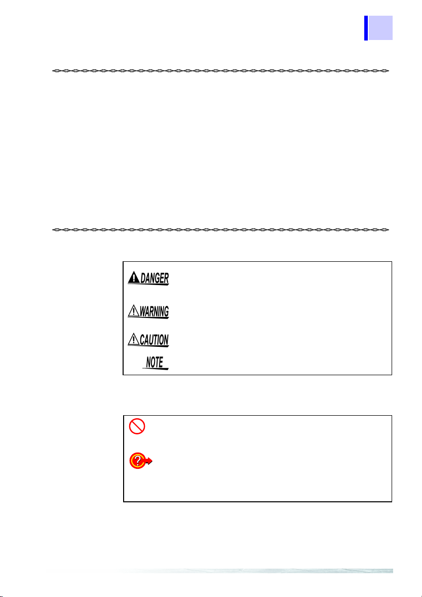
The following symbols in this manual indicate the relative importance of cautions and warnings.
Indicates that incorrect operation presents an
extreme hazard that could result in serious injury or
death to the user.
Indicates that incorrect operation presents a significant hazard that could result in serious injury or
death to the user.
Indicates that incorrect operation presents a possibility of injury to the user or damage to the product.
Advisory items related to performance or correct
operation of the product.
1
2
3
4
5
6
7
8
Other Symbols
❖
*
Indicates the prohibited action.
Indicates the reference.
Indicates quick references for operation and reme-
dies for troubleshooting.
Indicates terminology explained at the bottom of
the page.
9
10
11
Page 6

Quick Start Manual
2
Page 7
3
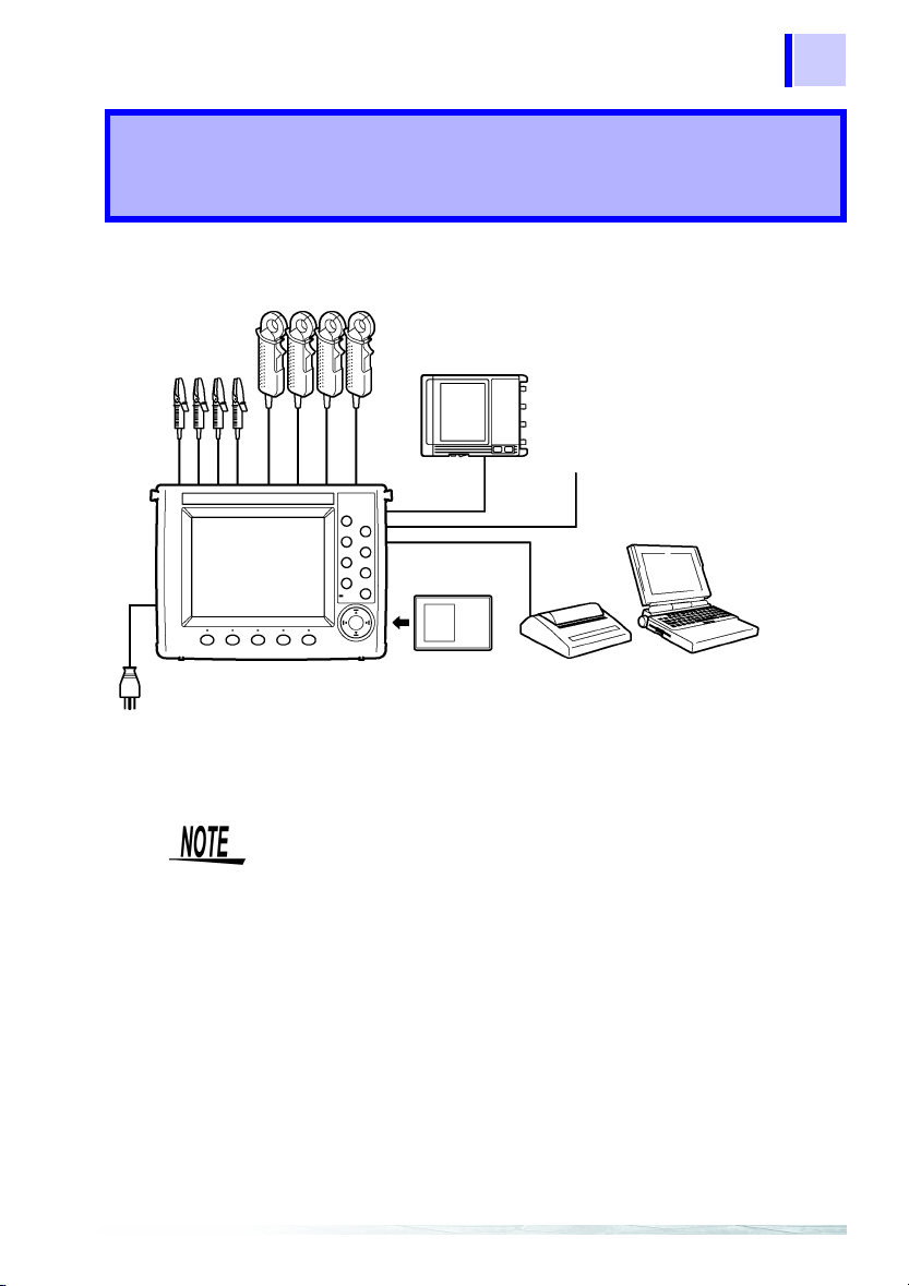
Parts Names
❖4 "Connecting to Lines to be Measured" (page 35)
❖11 "Using D/A Output (3169-21 only)"
(page 157)
Recorder, logger
D/A output
(3169-21)
PC card
❖7.2 "Using a PC Card"
(page 117)
❖3 "Measurement Preparations"
(page 25)
*: The RS-232C is connected to a printer or PC.
The reference pages referred to above are those in the instruction
manual.
EXT I/O
RS-232C
1
❖10 "Using the External Input/
Output Terminal" (page 151)
❖9 "Using the Instrument with
a Computer" (page 145)
PC
Printer
❖8 "Using a Printer"
(page 137)
1
2
3
4
5
6
7
8
9
10
11
Page 8
Quick Start Manual
4
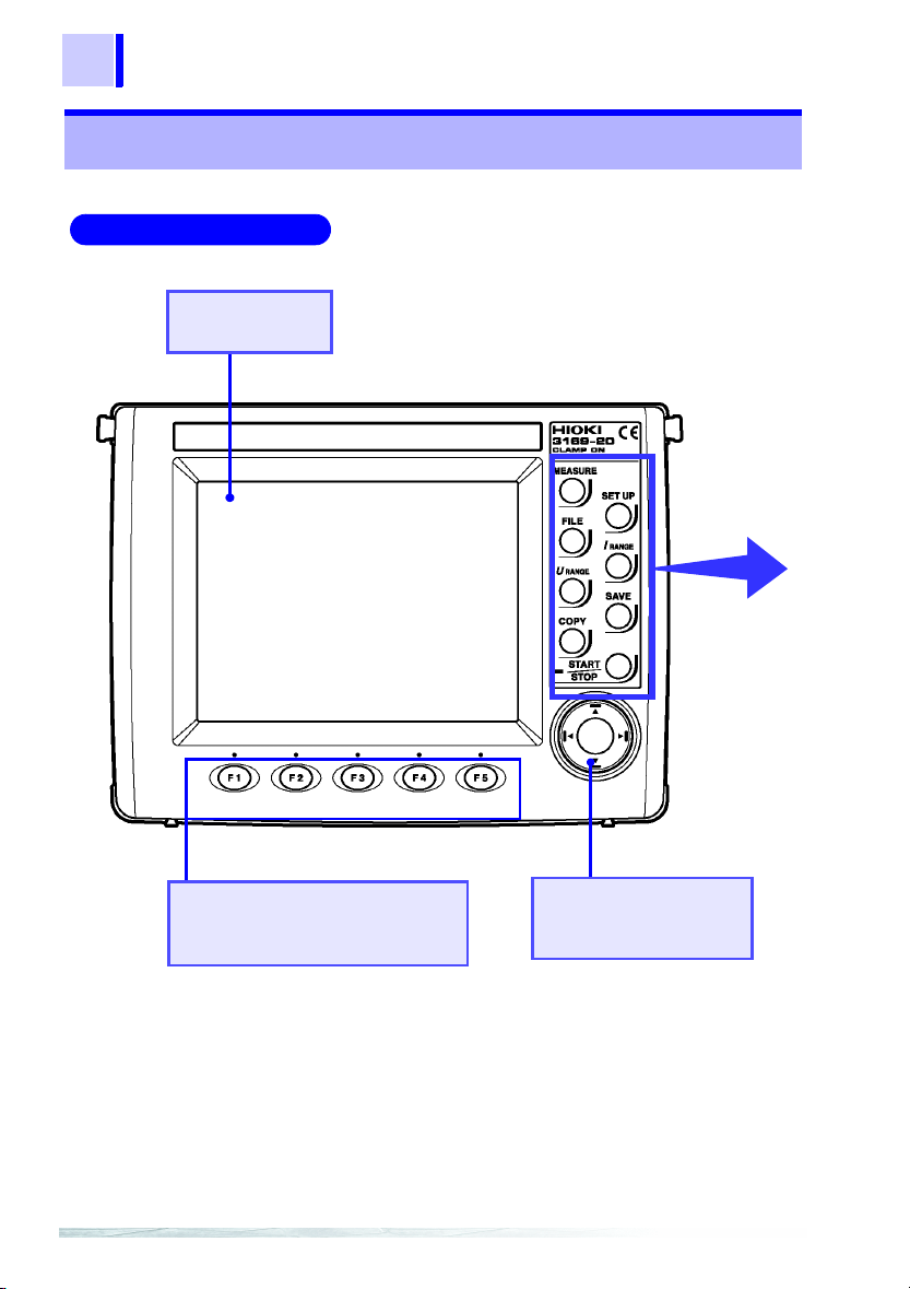
1.1 Instrument Labels and Functions
1.1 Instrument Labels and Functions
Front Panel
Display
5.7-inch STN LCD
Function (F1-F5) keys
Selects or switches the screens
and setting items.
Cursor key
These keys move the cursor on the screen.
Page 9
1.1 Instrument Labels and Functions
5
1
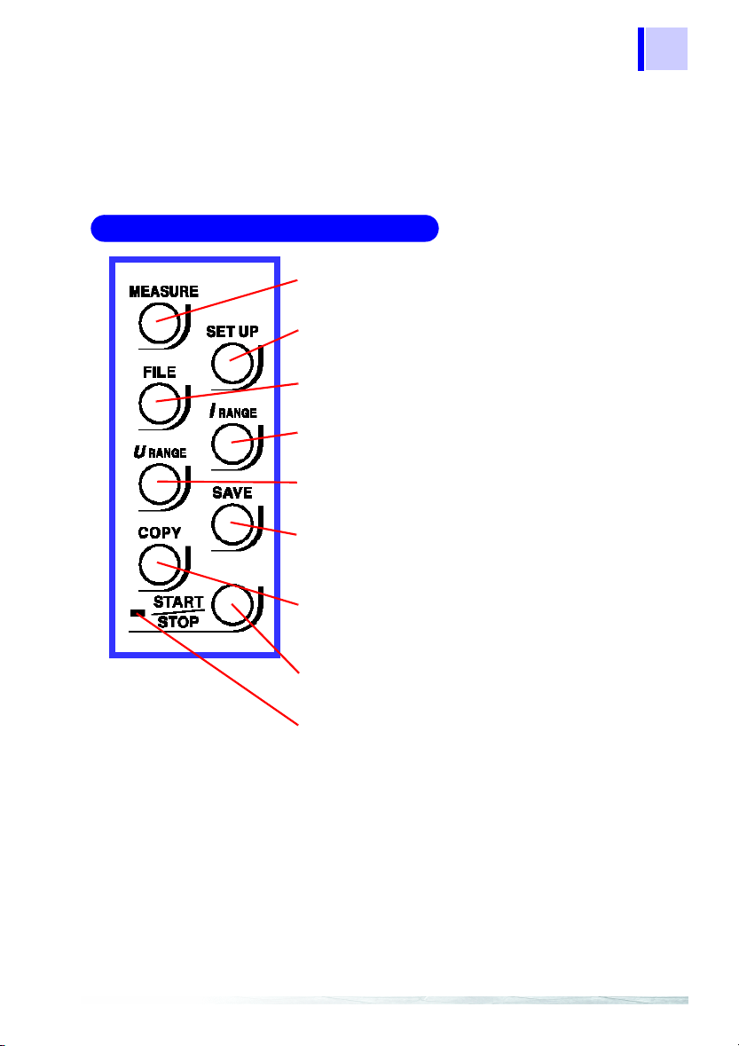
Front Panel Enhanced View
MEASURE key
Switches to a screen that displays measurements.
SET UP key
Switches to a screen that displays settings.
FILE key
Used to work on files.
I RANGE key
Sets the current measurement range for the circuit
to be measured on-screen.
U RANGE key
Sets the voltage measurement range.
SAVE key
Enables the manual saving of measurement data
on the PC card or in internal memory. Manual saving is not possible during time-series measurement.
COPY key
Outputs screen image data to the PC card, internal
memory, or a printer.
START/STOP key
Starts or stops time-series measurements including
integration measurement.
2
3
4
5
6
7
8
9
START/STOP LED
Flashes in green while the instrument is standing by
for time-series measurement, and lights in green
while the instrument is performing time-series measurement.
10
11
Page 10
Quick Start Manual
6
1.1 Instrument Labels and Functions
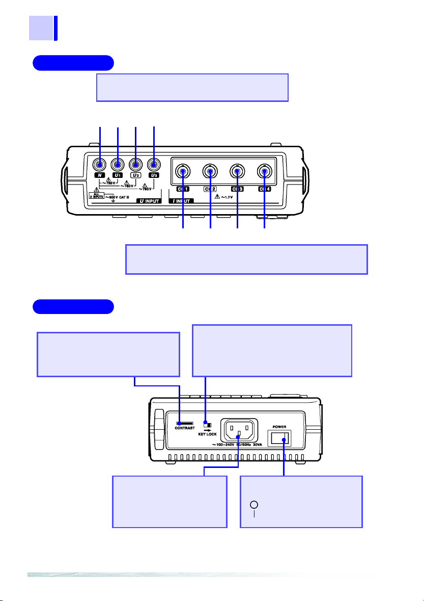
Top Panel
Left Panel
Voltage Input terminals
Connect the supplied 9438-03 VOLTAGE CORD.
Black Red Yellow Blue
NU1U2U
3
CH1 CH2 CH3 CH4
Current Input terminals
Connect an optional clamp-on sensor.
Contrast Control Knob
(CONTRAST)
Adjusts the contrast of the screen.
AC Power Inlet
Connects the power cord.
The supply voltage ranges
from 100 V to 240 V.
KEY LOCK switch
Sliding this switch in the direction of the
arrow disables all key operation except
the POWER switch.
POWER switch
Turns the instrument on and off.
: Power OFF
: Power ON
Page 11
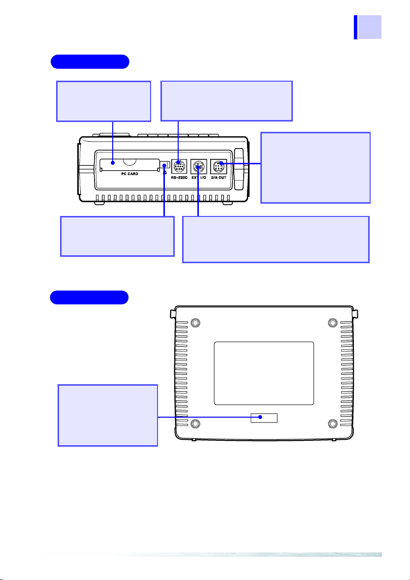
Right Panel
7
1.1 Instrument Labels and Functions
PC Card slot
A PC Card can be
inserted here.
Eject button
Press this button to eject a
PC Card from the slot.
Rear Panel
RS-232C Interface connector
Connects to a PC or printer using
an RS-232C cable.
D/A Output Terminal
(D/A OUT)
Installed in the 3169-21
only. Connects the supplied 9441 connection cable. Used for analog
output.
External Input/Output Terminal (EXT I/O)
Connects the optional 9440 connection cable.
Used to start and stop time-series measurement,
and control data storage on the PC card.
1
2
3
4
5
6
7
8
Number plate
Contains manufacturer’s ID
numbers. Please do not remove, as this information is
reguired for product management.
9
10
11
Page 12
Quick Start Manual
8
1.2 Screen Names and Display Elements
1.2 Screen Names and Display Elements
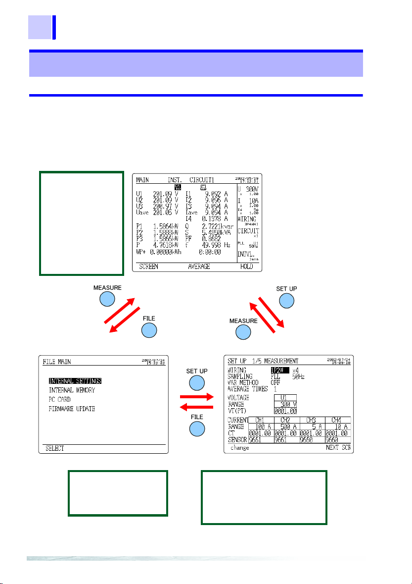
1.2.1 Screen Configuration
The screens are divided into three basic types: measurement
screens, setting screens, and file screens. Each screen is selected
using three panel keys:
Measurement screen
MAIN
POWER
INTEGRATE
DEMAND
ZOOM
HARMONIC LIST
HARMONIC GRAPH
WAVEFORM
WIRING CHECK
WIRING DIAGRAM
MEASURE, SET UP
, and
FILE
.
File screen
INTERNAL SETTINGS
INTERNAL MEMORY
PC CARD
FIRMWARE UPDATE
Setting screen
MEASUREMENT
DATA OUTPUT
SAVE, PRINT ITEMS
SYSTEM
D/A OUTPUT
(3169-21 only)
Page 13

1.2.2 Common Display
9
1.2 Screen Names and Display Elements
This section of the screen shows information common to all measurement screens (except the zoom screen and the wiring diagram
screen).
Common Display
Time
Range
Wiring
No. of circuits
Synchronization method
Interval
Time Displays the current time.
Range Displays the voltage range and current range of
Wiring Displays the wiring method set on the setting
No. of circuits Displays the number of circuits to be measured
Synchronization
method
Interval Displays the interval set on the setting screen.
the on-screen circuit. The VT(PT) ratio and CT
ratio are shown under these ranges. The current
range and CT ratio of I4 are shown only when
3P4W4I is set as the wiring method.
screen.
as set on the setting screen.
Displays the synchronization method and fre-
quency of the line to be measured as set on the
setting screen.
1
2
3
4
5
6
7
8
9
10
11
Page 14

Quick Start Manual
10
1.2 Screen Names and Display Elements
1.2.3 On-Screen Indicators
Goes on when the reactive-power-meter method is
ON.
Goes on when the displayed measurement is held.
Goes on when the medium for saving data is set to
PC card. Flashes when the PC card is accessed.
Goes on when the medium for saving data is set to
internal memory. Flashes when the internal memory
is accessed.
Goes on when the PC card or internal memory is full.
Goes on when the device to be connected to the RS232C is set to PC.
Goes on when the device to be connected to the RS232C is set to printer.
Goes on when the PLL is unlocked; the synchronization method is automatically switched over to the
fixed clock.
Goes on when the keys are locked.
Goes on when the voltage or current dynamic range
is exceeded.
Displayed when the range is exceeded.
U3* and I3* indicate that the data is obtained by calculating the 2-voltage, 2-current measurement results when 3P3W2M (three-phase, 3wire, 2-power-meter method) is selected.
❖
Instruction manual "Appendix" (page 195)
Page 15

2.1 Outline
11
Power Measurement
2.1 Outline
This chapter explains setting and measurement procedures using
the following conditions.
Measure the power of a Three-phase 3-wire line for 7 days.
Measurement location:
A Tree-phase 3-wire 200 V line of a switchboard (50 Hz, 50 A load)
Setting:
Time-series measurement start time: 2002/06/20 08:00
Time-series measurement stop time: 2002/06/27 08:00
Data is automatically output to the PC card at 5-minute intervals.
Average value (voltage, current, and power) and integrated power are
stored on the PC card. The reactive power-meter method is not used.
S
O
U
R
C
E
9438-03 VOLTAGE CORD
Upper side of the
3169-20/21
Red
A
Black
B
C
Yellow
2
L
O
A
D
9661 CLAMP ON SENSOR
1
2
3
4
5
6
7
8
3169-20/21
Face the arrow toward the Load
Instrument and Accessories Required for Measurement
Power cord
9438-03 VOLTAGE CORD
1 set (4 cords)(One each red, yellow,
blue, and black cords.)
9661 CLAMP ON SENSOR
x 2
PC card
9
10
11
Page 16

12
Quick Start Manual
2.1 Outline
Setting Screens under the Example Conditions
ÅîéûånóÒê›íËâÊñþÅî
<MEASUREMENT>
WIRING
2-power-meter method)
Number of circuits : X 1 (1 circuit)
SAMPLING : PLL
Measured frequency: 50 Hz
VAR METHOD : OFF
AVERAGE TIMES : 1
VOLTAGE RANGE : 300 V
VT (PT) : 0001.00
CURRENT RANGE : 50 A
CT : 0001.00
SENSOR : 9661
: 3P3W2M
(Three-phase 3-wire,
<DATA OUTPUT>
MEAS. START : TIME
MEAS. STOP : TIME
INTERVAL TIME : 5 min
SAVE IN... : PC CARD
DATA FILE NAME : INTEG
(2002/06/20 08:00)
(2002/06/27 08:00)
<SAVE, PRINT ITEMS>
NORM. MEAS.: ON
HARMONIC : OFF
INTEG. & DEM.: ON
INST. : OFF
AVE . : ON
MAX. : OFF
MIN. : OFF
Page 17

2.2 Measurement Procedure
2.2 Measurement Procedure
13
Measurement
Preparations
(page 14)
Connect to the
Line to be
Measured
(page 18)
Perform
Measurement
(page 26)
1. Connecting the Power Cord
2. Connecting the Voltage Cords
3. Connecting the Clamp-On Sensor
4. Inserting a PC Card
5. Turning the Power On
1. Setting the wiring details
2. Displaying the Wiring Diagram
3. Connectting the voltage cords and
clamp-on sensor to the line to be
measured
4. Checking the Wiring
1. Setting the measurement conditions
2. Confirm range
3. Start measurement
4. Stop measurement
1
2
3
4
5
6
7
8
9
Shutdown Procedure
1. Disconnect the voltage cords and
clamp-on sensor from the measured
line.
2. Turn off the power to the 3169-20/
21.
3. Disconnect the power cord from the
AC outlet.
4. Remove the PC card from the 3169-
20/21 and analyze the saved data
on PC.
10
11
Page 18

Quick Start Manual
14
2.3 Measurement Preparations
2.3 Measurement Preparations
1. Connecting the Power Cord
• Before turning the product on, make sure the source voltage matches that indicated on the product's power connector. Connection to an improper supply voltage may damage
the product and present an electrical hazard.
• To avoid electric shock and ensure safe operation, connect
the power cable to a grounded (3-contact) outlet.
Connect the power cord to
1.
the AC power inlet.
Plug the power cord into the
1
2.
AC mains outlet.
2
Page 19

2.3 Measurement Preparations
2. Connecting the Voltage Cords
15
Connect the voltage cords to the product first, and then to
the active lines to be measured. Observe the following to
avoid electric shock and short circuits.
• Voltage cord should only be connected to the secondary
side of a breaker, so the breaker can prevent an accident if
a short circuit occurs. Connections should never be made
to the primary side of a breaker, because unrestricted current flow could cause a serious accident if a short circuit
occurs.
• Do not allow Do not allow the voltage cable clips to touch
two wires at the same time. Never touch the edge of the
metal clips. Never touch the edge of the metal clips.
• Voltage input terminals U
terminal and are not insulated. To avoid the risk of electric
shock, do not touch the terminals.
• For safety reasons, when taking measurements, only use the
9438-03 VOLTAGE CORD provided with the product.
• The supplied voltage cords consist of one each red, yellow, blue
and black cords. Connect only the cords actually needed for
measurement. Cords not being used for measurement should
be disconnected.
Black
Red
Voltage input terminals
Yellow
, U2, and U3 are common to the N
1
Connect the 9438-03 VOLTAGE
CORD to the voltage input terminals of the 3169-20/21.
1
2
3
4
5
6
7
8
9
Insert plugs all the
way in.
10
11
Page 20

Quick Start Manual
16
2.3 Measurement Preparations
3. Connecting the Clamp-On Sensor
Connect the clamp-on sensors to the product first, and then
to the active lines to be measured. Observe the following to
avoid electric shock and short circuits.
• Clamp sensor should only be connected to the secondary
side of a breaker, so the breaker can prevent an accident if
a short circuit occurs. Connections should never be made
to the primary side of a breaker, because unrestricted current flow could cause a serious accident if a short circuit
occurs.
• When the clamp sensor is opened, do not allow the metal
part of the clamp to touch any exposed metal, or to short
between two lines, and do not use over bare conductors.
• To prevent damage to the product and sensor, never connect or disconnect a sensor while the power is on.
• The current input terminals of the 3169-20/21 are not insulated. To avoid the risk of electric shock, only use the specified optional clamp-on sensor.
Red
Yellow
3169-20/21 Current input
terminal
connector guide pins
When disconnecting the BNC connector, be sure to release the
lock before pulling the connectors apart. Forcibly pulling the connector without releasing the lock, or pulling on the cable, can
damage the connector.
Current input terminas
BNC plug slots
Lock
Connect the 9661 CLAMP ON
SENSOR to the current input terminals of the 3169-20/21.
Align the slots in the BNC plug
with the guide pins on the connector at the instrument side, then
push and turn the plug clockwise.
(to unplug the connector, push the
plug and turn it counterclockwise
before pulling it apart.)
Page 21

4. Inserting a PC Card
17
2.3 Measurement Preparations
Use only PC Cards sold by HIOKI. Compatibility and performance are not guaranteed for PC cards made by other manufacturers. You may be unable to read from or save data to
such cards.
• The PC card or the instrument can be damaged if the card is
inserted forcefully in the wrong direction.
• Never eject a PC card while it is being accessed by the instrument. Data on the PC card may be lost.
❖
Instruction manual 7.2 "Using a PC Card" (page 117)
5. Turning the Power On
Before turning the product on, make sure the source voltage
matches that indicated on the product's power connector.
Connection to an improper supply voltage may damage the
product and present an electrical hazard.
Open the cover and insert the
PC card with the arrow facing
up and in the direction of the PC
card slot, as far as it will go.
Turn the POWER switch ON ( | ).
1
2
3
4
5
6
7
8
Screen after the
power is turned on
(Self-test screen)
As soon as the power is turned on,
the self-test screen appears. Upon
completion of the self test, display
switches to the measurement screen.
Model No. of the
product
Version No.
Internal memory
test result
9
10
11
Page 22

Quick Start Manual
18
2.4 Connect to the Line to be Measured
2.4 Connect to the Line to be Measured
1. Setting the wiring details
Set the 3169-20/21 to measure a three-phase 3-wire 200 V line (50
Hz, 50 A load) using the 9661 CLAMP ON SENSOR (500 A rated).
(1) Set the
wiring
to "3P3W2M."
NEXT
SCR
change
Press the
Press the
screen.
Move the cursor to "
Press the
F5
key to display the setting screen.
SET UP
(NEXT SCR) key to display the measurement setting
(change) key to display the selection window.
F1
WIRING
."
select
Select "
using the cursor key.
Press the
3P3W2M
"(Three-phase 3-wire, 2-power-meter method) by
(select) key.
F1
Page 23

2.4 Connect to the Line to be Measured
(2) Make sure the number of circuits to be measured is set to
"X1 (1 circuit)."
When multiple circuits of the same voltage system (the same transformer) are to be measured, use a preset between X2 (2 circuits)
and X4 (4 circuits).
19
1
2
3
1P2W X1 (1 circuit), X2 (2 circuits),
1P3W X1 (1 circuit), X2 (2 circuits)
3P3W2M X1 (1 circuit), X2 (2 circuits)
3P3W3M,3P4W,
3P4W4I
(3) Make sure the synchronization method
(4) Make sure the frequency of the line to be measured is set to "50
Hz."
(5) Make sure the reactive power-meter method is "OFF."
X3 (3 circuits), X4 (4 circuits)
X1 (1 circuit) only
(sampling)
is set to "PLL."
4
5
6
7
8
9
10
11
Page 24

Quick Start Manual
20
2.4 Connect to the Line to be Measured
(5) Make sure the displayed data averaging times is set to "1."
(6) Set the voltage range to "300 V."
Move the cursor to "
Select "
-
300 V
VOLTAGE RANGE
" using the function keys.
+
(7) Make sure the VT (PT) ratio is set to "1."
Set the VT (PT) ratio, if necessary.
(Example)
When the primary voltage is 6.6 kV and the secondary voltage is
110 V, the VT ratio is 60 (6600 V/110 V). In this case, as the rated
measurement voltage is 110 V, set the voltage range to 150 V.
."
Page 25

2.4 Connect to the Line to be Measured
(8) Make sure "9661" is selected as the clamp-on sensor to be used.
21
1
(9) Set the current range to "50 A."
Move the cursor to "
Select "
-
+
Selectable current ranges vary according to the clamp-on sensor
used.
Clamp-On Sensor and Current Range:
9660, 9695-03 5 A, 10 A, 50 A, 100 A
9661 5 A, 10 A, 50 A, 100 A, 500 A
9667-5 kA (5000 A range) 5 kA
9667-500 A (500 A range) 500 A
9669 100 A, 200 A, 1 kA
9694 0.5 A, 1 A, 5 A
9695-02 0.5 A, 1 A, 5 A, 10 A, 50 A
" using the function keys.
50A
CURRENT RANGE
2
3
4
."
5
6
7
8
9
(10) Make sure the CT ratio is set to "1."
Set the CT ratio, if necessary.
(Example)
When the primary current is 100 A and the secondary current is 5
A, the CT ratio is 20 (100 A/5 A). In this case, as the rated measurement current is 5 A, set the current range to 5 A.
10
11
Page 26

Quick Start Manual
22
2.4 Connect to the Line to be Measured
2. Displaying the Wiring Diagram
SCREEN
select
Press the
Press the
Move the cursor to "
Press the F1 (select) key; the wiring diagram will appear.
MEASURE
(SCREEN) key to display the selection window.
F1
key to display the measurement screen.
WIRING DIAGRAM
."
Page 27

2.4 Connect to the Line to be Measured
3. Connectting the voltage cords and clamp-on
sensor to the line to be measured
23
(Example)
Connect the 9438-03 voltage cords and the 9661 clamp-on sensor
to the line to be measured, while referring to the wiring diagram.
We recommend that the color of a voltage cord be matched to that
of the attached input-cord label used for the same channel.
9438-03 VOLTAGE CORD
S
O
U
R
C
E
Red
A
Black
B
C
Yellow
O
S
Source
9661 CLAMP ON SENSOR
Input cord label (Red)
Input cord label (Yellow)
D
A
O
L
E
C
R
U
Conductor
Current flow
direction arrow
Face the arrow toward the Load
L
O
A
D
Load
The arrows on the
clamp indicating the
direction of current
flow should point toward the load side.
1
2
3
4
5
6
7
8
9
Clip securely to metal parts
such as connection screws
or bus bars at the power
side.
10
OK
11
Clamp around only one conductor. Measurement is not possible if the clamp is placed around two
lines in a single-phase circuit, or three lines in a
three-phase circuit.
Page 28

Quick Start Manual
24
2.4 Connect to the Line to be Measured
4. Checking the Wiring
SCREEN
select
Press the
Press the
Move the cursor to "
Press the
The connection status is shown by the voltage, current vectors,
and the connection check result.
If the wiring check result is not "
MEASURE
(SCREEN) key to display the selection window.
F1
(select) key.
F1
key to display the measurement screen.
WIRING CHECK
."
," check the wiring.
OK
The wiring check function may indicate improper connection
("NG") even when the actual wiring is correct, or vice versa.
Check the vectors and measurement data as well.
Page 29

2.4 Connect to the Line to be Measured
The wiring check result is NG.
25
The voltage input
is NG.
The current input
is NG.
The voltage phase
is NG.
The current phase
is NG.
The phase difference (I-U) is NG.
The voltage balance is NG.
• Do the voltage clips grip the wires properly?
• Is the voltage cord properly inserted into the
voltage input terminal of the 3169-20/21?
• Is the clamp-on sensor securely inserted
into the current input terminals?
• Is the set current range too large for the
input level?
• Are the voltage cords connected to the correct terminals?
• Does the arrow of the clamp-on sensor point
to the load side?
• Is the clamp-on sensor connected to the correct terminals?
• Are the voltage cords and clamp-on sensor
properly connected?
• Does the arrow of the clamp-on sensor point
to the load side?
• Is the power factor of the line to be measured too low, such as 0.5 or less?
• Does the connection method of the line to be
measured differ from that set?
• Do the voltage clips grip the wires properly?
• Is the voltage cord properly inserted into the
voltage input terminal?
1
2
3
4
5
6
7
8
9
10
11
Page 30

Quick Start Manual
26
2.5 Perform Measurement
2.5 Perform Measurement
1. Setting the measurement conditions
DATA OUTPUT
• Measurement start:
2002/06/20 08:00
• Measurement stop:
2002/06/27 08:00
• Data is automatically output to the
PC card at 5-minute
intervals.
• Data file name:
INTEG
SAVE, PRINT ITEMS
Saves the average
value (voltage, Current, and Power) and
integrated power on a
PC card
(1) Set the measurement start time to "2002/06/20 08:00."
Before setting the measurement start time, make sure the current
date and time displayed on the screen are correct.
❖
Instruction manual 5.5.7 "Setting the Clock" (page 92)
NEXT
SCR
Press the
Press the
screen.
SET UP
F5
key to display the setting screen.
(NEXT SCR) key to display the data-output setting
Page 31

2.5 Perform Measurement
27
Move the cursor to "
TIME
(2) Set the measurement stop time to "2002/06/27 08:00."
Press the F2 (TIME) key.
MANUAL Measurement starts when the START/STOP key is pressed
TIME Measurement starts at the time set by users.
JUST Measurement will begin as soon as the internal clock reaches
❖
Instruction manual 5.3.1 "Setting the Time-Series Measurement Start
Method" (page 69)
Move the cursor to the measurement start time.
Set the measurement start time to "
-
function keys. (Cursor : Moves left to next digit; Cursor :
Moves right to next digit)
+
If F3 (AUTO) key is pressed when the cursor is at the measurement start time, the start time will be set to a date and time close
to the current time.
(default setting).
a time that is evenly divisible by the set interval.
+
MEAS. START
Decrements the number.
Increments the number.
."
2002/06/20 08:00
1
2
3
4
" using the
5
6
7
Move the cursor to "
Press the
TIME
MANUAL Measurement stops when the START/STOP key is pressed
TIME Measurement stops at the time set by users.
TIMER Measurement stops when the duration set by the users has
-
Move the cursor to the measurement stop time and set it to "
06/27 08:00
+
(TIME) key.
F2
."
MEAS. STOP
(default setting).
elapsed. 1 second to 8784 hours
."
8
9
10
11
2002/
Page 32

Quick Start Manual
28
2.5 Perform Measurement
(3) Set the interval time to "5 minutes."
change
select
Move the cursor to "
Press the
Select "
Press the
Interval setting
1/2/5/10/15/30/60
minutes
1/2/5/10/15/30
seconds
All wave
(change) key to display the selection window.
F1
" using the cursor key.
5 min
(select) key.
F1
Storable Data According to Interval Setting
/100/200/
500 ms
INTERVAL TIME
Normal mea-
surement data
Yes Yes Yes
Yes Yes No
Yes
(Instantaneous
values only)
Binary data
."
integrated power/
demand measure-
ment data
No No
Harmonic mea-
surement data
(4) Make sure the medium for saving data to is set to "PC card."
Page 33

2.5 Perform Measurement
(5) Set the data output file name to "INTEG."
29
change
input
BS
enter
Move the cursor to "
Press the
Enter "
rection, press the
delete one letter.
Press the
• The file is saved as "INTEG.csv" on the PC card.
• If a filename is not specified or a file with the same name exists
on the PC card, the file will automatically be named
"69MEASXX" (XX: 00 to 99).
(change) key to display the selection window.
F1
INTEG
(enter) key.
F3
DATA FILE NAME
" using the cursor and F1 (input) key. To make a cor-
(BS) key. Pressing the F2 key once will
F2
."
1
2
3
4
5
6
7
8
9
10
11
Page 34

Quick Start Manual
30
2.5 Perform Measurement
(6) Set the data output items
NEXT
SCR
ON
Press the F5 (NEXT SCR) key to display the save/print items setting screen.
256 or less
7 days or more
Move the cursor to "
Press the
Turn ON "
(ON) key.
F1
" and "
AVE .
NORM. MEAS.
INTEG. & DEM.
."
" in a similar way.
All other items shall be turned OFF.
• Check the storable time. This indicates the length of time for
which the currently installed PC card stores data. If the storable time is shorter than the measurement time (7 days),
delete unnecessary files from the PC card or replace it with a
larger-capacity PC card.
• If the number of output is greater of equal to 256, all of the data
may not be read into common spreadsheet software.
• For details on settings for harmonics measurement-data output, see 5.4.4 "Setting Harmonic Measurement-data Output
Items" (page 82) of the instruction manual.
Page 35

2. Confirm range
31
2.5 Perform Measurement
Press the
Press the
range.
If you press the
sufficient margin, in consideration of fluctuations in the load current of the line to be measured.
MEASURE
U RANGE
I RANGE
3. Start measurement
Press the
Press the
mode (LED blinking).
The 3169-20/21 will automatically start measurement (LED
remaining ON) at the measurement start time.
Switch Over to Another Screen.
SCREEN
Press the F1 (SCREEN) key to display the selection window.
MEASURE
START/STOP
key to display the measurement screen.
key or
I RANGE
Key, it selects a current range with a
key to display the measurement screen.
key to place the 3169-20/21 in standby
key to select an appropriate
1
2
3
4
5
6
7
8
select
Select a screen to be viewed using the cursor key.
Press the
(select) key.
F1
9
10
11
Page 36

Quick Start Manual
32
2.5 Perform Measurement
4. Stop measurement
The 3169-20/21 will automatically stop measurement at the stop
time. The measurement data "INTEG.csv" has been saved on the
PC card.
Interrupt Measurement.
Press the
the time-series measurement?
yes
Press the F1 (yes) key.
All measurement data before the interruption is saved on the PC
card if the measurement is interrupted.
START/STOP
key. The message "
" is displayed for you to confirm.
Do you want to stop
Shutdown Procedure
1. Disconnect the voltage cords and clamp-on sensor from the
measured line.
2. Turn off the power to the 3169-20/21.
3. Disconnect the power cord from the AC outlet.
4. Remove the PC card from the 3169-20/21 and analyze the
saved data on PC.
Page 37

HIOKI 3169-20/21 CLAMP ON POWER HiTESTER
Quick Start Manual
Publication date: October 2003 Revised edition 2
Edited and published by HIOKI E.E. CORPORATION
Technical Support Section
All inquiries to International Sales and Marketing Department
81 Koizumi, Ueda, Nagano, 386-1192, Japan
TEL: +81-268-28-0562 / FAX: +81-268-28-0568
E-mail: os-com@hioki.co.jp
URL http://www.hioki.co.jp/
Printed in Japan 3169A983-02
• All reasonable care has been taken in the production of this
manual, but if you find any points which are unclear or in error,
please contact your supplier or the International Sales and
Marketing Department at HIOKI headquarters.
• In the interests of product development, the contents of this
manual are subject to revision without prior notice.
• Unauthorized reproduction or copying of this manual is prohibited.
Page 38

HEAD OFFICE
81 Koizumi, Ueda, Nagano 386-1192, Japan
TEL +81-268-28-0562 / FAX +81-268-28-0568
E-mail: os-com@hioki.co.jp / URL http://www.hioki.co.jp/
HIOKI USA CORPORATION
6 Corporate Drive, Cranbury, NJ 08512, USA
TEL +1-609-409-9109 / FAX +1-609-409-9108
3169A983-02 03-10H
Printed on recycled paper
 Loading...