

Page 1

3158
Instruction Manual
AC WITHSTANDING
VOLTAGE HiTESTER
Mar. 2019 Revised edition 12
3158A981-12 19-03H
EN
Page 2

Page 3

Contents
Inspection i
Safety Notes
Notes on Use
Contents and Indications of This Manual
iv
vi
Chapter 1 Overview 1
1.1 Product Introduction 2
1.2 Names and Functions of Parts
Chapter 2 Testing Arrangements 7
2.1 Connecting the Protective Ground Terminal 7
2.2 Wearing rubber gloves
2.3 Connecting the External I/O Connector
2.4 Power Cord Connection
2.5 Powering On and Off the Unit
2.6 Connecting the 9615 H.V. TEST LEAD
2.7 Connecting the REMOTE CONTROL BOX
2.8 Installation of the Unit
10
11
12
14
15
ii
3
8
9
2.9 Connection to the Measured Equipment
2.10 Startup Inspection
16
17
Chapter 3 Testing Method 19
3.1 State of the 3158 and Preset Parameters 20
3.2 Making Testing Arrangements (in READY State)
3.2.1 Selecting an Output-Voltage Range 23
3.2.2 Key-lock Function 23
3.2.3 Initial Settings for Optional Functions 24
3.3 Setting the "SETTING" State 25
3.3.1 Setting the Comparative Voltage Value 26
3.3.2 Setting the Upper (Lower) Level Value 27
3.3.3 Setting the Test Time 28
3.3.4 Examples of Settings 29
3.4 Starting a Test 32
3.4.1 Setting the Output Voltage 33
3.4.2 Executing a Test 35
22
3158A981-12
3.4.3 Screening in "TEST State" 37
3.5 PASS or FAIL Determination 38
3.5.1 "PASS" State 38
3.5.2 Screening in "PASS" State 39
Page 4

3.5.3 "FAIL" State 40
3.5.4 Screening in "FAIL" State 43
Chapter 4 Optional Functions 45
4.1 PASS Hold Function 48
4.2 FAIL Hold Function
4.3 Hold Function
4.4 Momentary Out
4.5 Double Action
4.6 FAIL Mode
4.7 RS Command [START]
4.8 Inter-lock Function
4.9 Voltage Comparator Position
4.10 Example of Optional Function Settings
4.11 Example of Optional Functions Use
49
50
52
53
54
55
56
57
58
59
Chapter 5 Saving/Loading Preset Values 61
5.1 Saving Preset Values 62
5.1.1 Procedure for Saving Data 63
5.1.2 Example of Saving 64
5.2 Loading Preset Values 66
5.2.1 Procedure for Loading Data 67
5.2.2 Example of Loading 68
Chapter 6 External Interface 71
6.1 External I/O Terminal 71
6.1.1 Signal Line 72
6.1.2 Example of Input Signal Connection 74
6.1.3 Example of Output Signal Connection 76
6.1.4 Inter-lock Function 78
6.1.5 Timing Chart of External I/O Terminal 80
6.2 Buzzer 83
Chapter 7 RS-232C Interface 85
7.1 Specifications 85
7.2 Connection Method
7.3 Command Transfer Methods
7.4 Command
7.5 Transmission and Response Formats
86
87
89
100
7.6 Command Summary
101
Page 5

Chapter 8 Maintenance and Inspection 103
8.1 Maintenance 104
8.2 Fuse Replacement
8.3 Troubleshooting
8.4 Displaying Errors
8.5 Resetting the System
8.6 External Dimensions
105
106
107
107
108
Chapter 9 Specifications 109
9.1 Basic Specifications 109
9.2 General Specifications
113
Appendix APPENDIX1
9613 REMOTE CONTROL BOX (SINGLE) APPENDIX1
9614 REMOTE CONTROL BOX (DUAL) APPENDIX2
9615 H.V. TEST LEAD (Standard Accessory) APPENDIX3
Table of Optional Functions APPENDIX4
Page 6

Page 7

────────────────────────────────────────────────────
Introduction
Thank you for purchasing the HIOKI "3158 AC WITHSTANDING VOLTAGE
HiTESTER". To obtain maximum performance from the product, please read this
manual first, and keep it handy for future reference.
Inspection
When you receive the product, inspect it carefully to ensure that no damage
occurred during shipping. In particular, check the accessories, panel switches, and
connectors. If damage is evident, or if it fails to operate according to the
specifications, contact your dealer or Hioki representative.
i
NOTE
Checking the main unit and accessories
Main unit
"3158 AC WITHSTANDING VOLTAGE HiTESTER."
Accessories
Verify that the following standard accessories are complete.
(1) Instruction Manual
(2) Spare fuse (built into the power inlet)
(3) Grounded three-core power cord
(4) 9615 H.V. TEST LEAD
(High voltage and return side )
Shipment of the unit
If reshipping the unit, preferably use the original packing.
Warranty
HIOKI cannot be responsible for losses caused either directly or indirectly by the
use of the 3158 with other equipment, or if ownership is transferred to a third party.
1
1
1
1
Before using the product, make sure that the insulation on the test leads is
undamaged and that no bare conductors are improperly exposed. Using the
product in such conditions could cause an electric shock, so contact your
dealer or Hioki representative for repair.
────────────────────────────────────────────────────
Introduction
Page 8
ii
────────────────────────────────────────────────────
Safety Notes
DANGER
Thisproduct is designed to comply with IEC 61010 Safety Standards, and
has been thoroughly tested for safety prior to shipment. However,
mishandling during use could result in injury or death, as well as damage
to the product. However, using the product in a way not described in this
manual may negate the provided safety features.
Be certain that you understand the instructions and precautions in the
manual before use. We disclaim any responsibility for accidents or
injuries not resulting directly from product defects.
This manual contains information and warnings essential for safe operation of the
product and for maintaining it in safe operating condition. Before using the
product, be sure to carefully read the following safety notes.
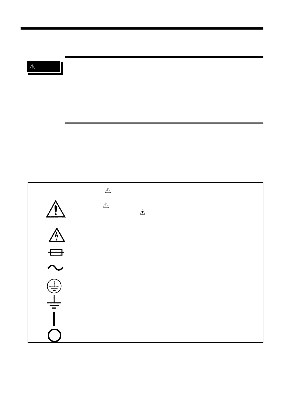
Safety symbols
・
The
should refer to a corresponding topic in the manual (marked with
the
・
In the manual, the
information that the user should read before using the product.
symbol printed on the product indicates that the user
symbol) before using the relevant function.
symbol indicates particularly important
Indicates that dangerous voltage may be present at this terminal.
Indicates a fuse.
Indicates AC (Alternating Current).
Indicates a protective conductor terminal.
Indicates a functional earth terminal.
Indicates the ON side of the power switch.
Indicates the OFF side of the power switch.
────────────────────────────────────────────────────
Introduction
Page 9
iii
────────────────────────────────────────────────────
The following symbols in this manual indicate the relative importance of cautions
and warnings.
DANGER
WARNING
CAUTION
NOTE
DANGER
Indicates that incorrect operation presents an extreme hazard that
could result in serious injury or death to the user.
Indicates that incorrect operation presents a significant hazard
that could result in serious injury or death to the user.
Indicates that incorrect operation presents a possibility of injury to the
user or damage to the product.
Advisory items related to performance or correct operation of the product.
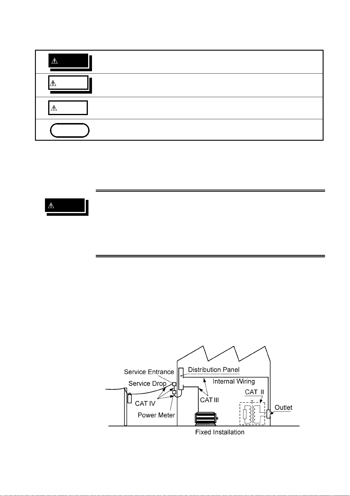
Measurement categories
To ensure safe operation of measuring instruments, IEC 61010 establishes safety
standards for various electrical environments, categorized as CAT II to CAT IV, and
called measurement categories.
・
Using a measuring instrument in an environment designated with a
higher-numbered category than that for which the instrument is rated
could result in a severe accident, and must be carefully avoided.
・
Never use a measuring instrument that lacks category labeling in a
CAT II to CAT IV measurement environment. Doing so could result in
a serious accident.
CAT II: Whe n directly me as ur ing t he electrical outlet receptacles of t he p ri mar y
electrical circuits in e qui pme nt connected to a n AC electrical outlet by a power
cord (portable tools, household appliances, etc.)
CAT II I : When measuring the pr imary electrical circuits of heavy equipment (fixed
installati ons) connected directly to the distr ibuti on panel, and feeders from the
distribution panel to outlets
CAT IV: Wh en mea sur ing t he circuit from t he service drop to t he service entranc e, an d to
the power met er and prim ary o verc urrent protection device (di stribution panel)
────────────────────────────────────────────────────
Introduction
Page 10
iv
────────────────────────────────────────────────────
Notes on Use
Follow these precautions to ensure safe operation and to obtain the full benefits of
the various functions.
DANGER
WARNING
To avoid any life-threatening electric shock accidents, ensure that the
following rules are observed.
・
The AC Withstanding Voltage Hitester is a dangerous product which
discharges high voltages. To prevent getting electrocuted, always
wear high-voltage protective rubber gloves when carrying out any
operation.
・
Be careful when using the product and ensure that you do not touch
this product, any tested object that is connected or any H.V. TEST
LEAD, etc.
・
To avoid electric shock, do not remove the cover panel. The internal
components of the product carry high voltages and may become very
hot during operation.
・
Vinyl shield on 9615 H.V. TEST LEAD alligator clip is not high voltage
insulated. DO NOT touch when high voltage is applied.
・
To avoid electric shock, be sure to connect the protective ground
terminal to a grounded conductor.
・
The unit is constructed so as to be connected to a ground line via a
three-core power cord that is supplied with the unit. To avoid
electric shock and ensure safe operation, connect the power cable to
a grounded (3-contact) outlet.
・
Before turning the product on, make sure the source voltage matches
that indicated on the product's power connector. Connection to an
improper supply voltage may damage the product and present an
electrical hazard.
・
To avoid electric shock, do not allow the product to get wet, and do
not use it when your hands are wet.
・
This product should be installed and operated indoors only, between
0℃and 40℃and 80%RH max. Do not use the unit in direct sunlight,
dusty conditions, or in the presence of corrosive gases.
・
Replace the fuse only with one of the specified characteristics and
voltage and current ratings. Using a non-specified fuse or shorting
the fuse holder may cause a life-threatening hazard.
Fuse type: 250VT8AL(3158-01
250VT4AL(3158-03 to 3158-05
)
)
────────────────────────────────────────────────────
Introduction
Page 11

v
────────────────────────────────────────────────────
・
CAUTION
Do not insert a board other than optional interface boards into the Interface
slot. The unit software or calibration data may be lost.
・
To avoid electrocution, turn off the power to all devices before pluggingor
unplugging any of the interface connectors.
・
To avoid damaging the power cord, grasp the plug, not the cord, when
unplugging the cord from the power outlet.
・
To avoid damaging test leads, do not kink or pull on the leads.
・
Keep in mind that, in some cases, conductors to be measured may be hot.
・
Take care not to block the ventilation openings on the sides of the unit.
・
For safety reasons, only use the 9615 H.V. TEST LEAD for measurement.
・
To avoid damage to the product, protect it from vibration or shock during
transport and handling, and be especially careful to avoid dropping.
・
In the event that the equipment malfunctions in any manner during use,
turn off the power immediately, and contact your dealer or HIOKI
representative.
・
To avoid electric shock, do not exceed the lower of the ratings shown on
the instrument and test leads.
NOTE
・
Do not use the unit near any device which generates strong electromagnetic
radiation or near a static electrical charge, as these may cause errors.
・
This instrument may cause interference if used in residential areas. Such use
must be avoided unless the user takes special measures to reduce
electromagnetic emissions to prevent interference to the reception of radio and
television broadcasts.
────────────────────────────────────────────────────
Introduction
Page 12

vi
────────────────────────────────────────────────────
Contents and Indications of This Manual
Chapter 1: Overview
Describes an overview, features, and the names and functions of the parts of the
unit.
Chapter 2: Testing Arrangements
Describes particulars of testing arrangements.
Chapter 3: Testing Method
Describes procedures for setting, testing, and test results judgment.
Chapter 4: Optional Functions
Describes procedures for setting optional functions.
Chapter 5: Saving/Loading Preset Values
Describes procedure for saving and loading test values.
Chapter 6: External Interface
Describes use of the external I/O and REMOTE CONTROL BOX.
Chapter 7: RS-232C Interface
This chapter explains the testing procedure using RS-232C.
Chapter 8: Maintenance and Inspection
Covers the maintenance and inspection, fuse replacement, and ultimate disposal.
Chapter 9: Specifications
Contains the unit specifications such as the general specifications, measurement
accuracy, etc. of the unit.
Appendix:
Covers the options of the unit.
────────────────────────────────────────────────────
Introduction
Page 13

1
────────────────────────────────────────────────────
Chapter 1
1
Overview
3
4
5
6
7
8
9
10
11
12
13
14
A
────────────────────────────────────────────────────
Page 14

2
────────────────────────────────────────────────────
1.1 Product Introduction
(1) Easy testing conforming to standards
The unit allows pressure tests based on a wide variety of standards to be conducted.
The timer function and the comparative screening function using upper- and lowerlevel values provide accurate test results. The unit does not operate until the output
voltage preset using the voltage adjustment knob is within±5% (output voltage
1kV:±50 V) of the comparative voltage value, thus further ensuring accurate
readings.
(2) Fluorescent indicator
The large, easy-to-read fluorescent display permits q uick checking of the testing
state and result.
(3) Analog Voltage Measurement
The voltage is digitally displayed on the fluorescent indicator. This value can also
be checked on the analog voltmeter.
(4) Zero-Toggle Switch
This function ensure that test voltage can be toggled on and off only at a sine wave
zero crossings, to prevent damage to the device under test if it happens to be faulty.
(5) Saving testing set values
This unit is provided with a function for saving the set values used in a test,
allowing quick switching between different testing set values to meet a variety of
standards and regulations. Up to 20 values may be saved.
The values i mmediately prior to a power shutdown are saved in the unit. These
values are valid at the next startup.
(6) REMOTE CONTROL BOX
The 9613 REMOTE CONTROL BOX (SINGLE) or the 9614 REMOTE CONTROL
BOX (DUAL) can be connected to the external switch terminal to perform 3158
start/stop control.
(7) External I/O
The external I/O terminal generates signals according to the state of the 3158. It
can be used to feed signals for the start and stop key.
(8) RS-232C interface as a standard feature
Automatic testing and saving of the test results are possible with the use of a
computer.
≦
────────────────────────────────────────────────────
1.1 Product Introduction
Page 15
3
────────────────────────────────────────────────────
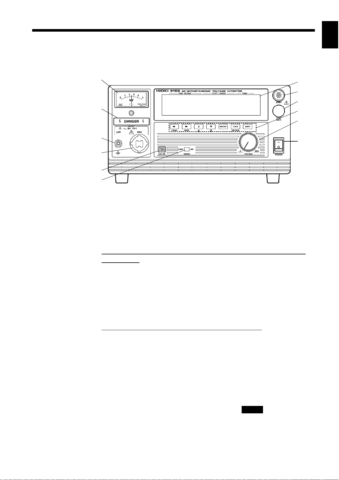
1.2 Names and Functions of Parts
Front panel
1
7
8
9
2
10
11
1
3
4
3
4
5
6
1 Analog voltmeter
Indicates output voltage.
2 Danger Lamp
This lamp lights to warn that voltage is present between the terminals during
testing.
When the DANGER lamp is lit, never touch the HIGH terminal, probe, or
tested object.
3LOWTerminal
The LOW terminal is a low-voltage terminal for voltage outputs. It has the same
electric potential as the unit body.
4 HIGH Terminal
The HIGH terminal is a high-voltage terminal for voltage outputs. A high voltage
is generated between this terminal and the LOW terminal.
When the DANGER lamp is lit, never touch this terminal.
12
5
6
7
8
9
10
11
5 External Switch Terminal
Used for the signal line for the remote-control box.
6 Range Selection switch
Used to switch among output-voltage ranges.
7 VFD ( Vacuum Fluorescent Display )
Displays various kinds of information, such as test state and results.
8 START key
Used to start a test. This key functions only when the READY lamp is lit.
9 STOP key
Normally used to terminate a test.
────────────────────────────────────────────────────
1.2 Names and Functions of Parts
12
13
14
A
Page 16
4
────────────────────────────────────────────────────
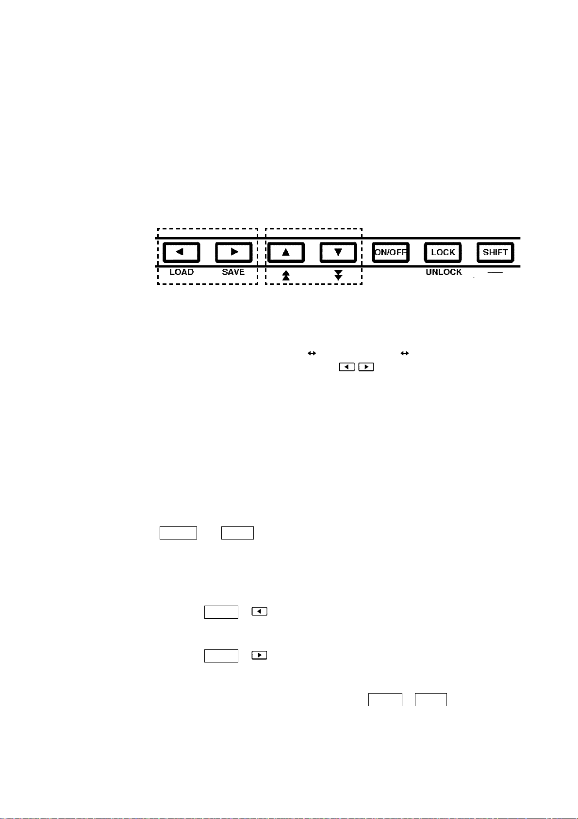
10 Rubber keys
The seven rubber keys include six function keys and a SHIFT key.
The six function keys offer a variety of settings, used in combination with the
SHIF T key.
11 Output Voltage Knob
Sets the output voltage.
12 Main power switch
Powers the 3158 on or off.
Rubber keys
1 2 3 4 5
1 Left/Right cursor key
Moves the flashing cursor. The switching range is preset before shipment:
Preset Comparative voltage value
To display the flashing cursor, press the
Upper limit Value Test time.
/ keys. The cursor appears,
displaying the preset comparative voltage value.
2 Up/Down cursor key
Changes the position at which the flashing cursor appears.
3 ON/OFF key
Switches on/off the set value for the position of the flashing cursor.
However, this key can't perform the switching on/off of the preset Upper level
Value. If turned off, the set value is not used in testing.
4 LOCK key
Used to lock the keys. When pressed, the LOCK key disables all keys except the
START
key,
STOP
key, and Key Lock Cancel key. See 3.2.2, "Key-lock
Function."
5 SHIFT key
Used in combination with other keys.
(1)
Displaying the Preset-data loading screen
Press
SHIFT
information, see Chapter 5, "Saving/loading the Parameters Set."
(2)
Displaying the Preset-data saving screen
Press
SHIFT
information, see Chapter 5, "Saving/Loading Preset Values."
(3)
Disabling the key lock function
To disable the key lock function, press the
+ keys to display the Preset-data loading screen. For more
+ keys to display the Preset-data saving screen. For more
SHIFT+LOCK
keys.
────────────────────────────────────────────────────
1.2 Names and Functions of Parts
Page 17

5
────────────────────────────────────────────────────
Rear panel
1
2
3
4
1 Fuse Holder
Contains a power fuse.
1
5
3
6
4
5
6
2 Power inlet
Connect the grounded three-core power cord supplied here. Integrated with a fuse
holder.
3 RS-232C terminal
Used for remote control with RS-232C.
4 Protective ground terminal
Used to earth a protective ground wire. Be sure to make grounding connections
before starting a test.
5 Buzzer adjustment knob
Used for buzzer sound adjustment. Two knobs are provided: one for PASS
screening and one for FA IL screening.
6 External I/O terminal
For output of 3158 state and input of start and stop signals.
7
8
9
10
11
12
13
────────────────────────────────────────────────────
1.2 Names and Functions of Parts
14
A
Page 18

6
)
)
────────────────────────────────────────────────────
9615 H.V. TEST LEAD
1
High-voltage side(red
2
1
Low-voltage side(black
3
1 Alligator clip
Connect to a test point on the tested object.
Vinyl shield on 9615 H.V. TEST LEAD alligator clip is not high voltage
insulated. DO NOT touch when high voltage is applied.
2 High-voltage output plug
Connect to the HIGH terminal on the unit.
3 Low-voltage output plug
Connect to the LOW terminal on the unit.
REMOTE CONTROL BOX
9613 REMOTE CONTROL BOX (SINGLE)
1
4
3
2
9614 REMOTE CONTROL BOX (DUAL)
1
2
1OPERATEswitch
Used to enable remote-control operation. When this switch is ON, the START and
STOP keys for remote control are active. Changing this switch during testing will
forcibly terminate the test.
2 START key
Works in the same manner as the
REMOTE CONTROL BOX (DUAL), the two START switches must be pressed.
START
key on the unit. With the 9614
4
3
2
3 STOP key
Works in the same manner as the
during a test or when a voltage is being output.
STOP
key on the unit. The STOP key is ON
4 Switch signal-line plug
Connect to the external switch terminal on the unit.
────────────────────────────────────────────────────
1.2 Names and Functions of Parts
Page 19

7
────────────────────────────────────────────────────
Chapter 2
1
2
Testing Arrangements
2.1 Connecting the Protective Ground Terminal
・
WARNING
To avoid electric shock, be sure to connect the protective ground
terminal to a grounded conductor.
・
To avoid electric shock, connect the protective ground terminal to a
grounded conductor before making any other connections.
(1) Using a Phillips-head screwdriver, remove the protective ground terminal from
the rear of the unit.
(2) Connect an electric wire with a sufficient current capacity to the protective
ground terminal, and secure the wire using a Phillips-head screwdriver.
(3) Ground the other end of the wire.
3
4
5
6
7
8
9
10
11
12
13
14
A
────────────────────────────────────────────────────
2.1 Connecting the Protective Ground Terminal
Page 20

8
────────────────────────────────────────────────────
2.2 Wearing rubber gloves
DANGER
To avoid any life-threatening electric shock accidents, ensure that the
following rules are observed.
・
The AC Withstanding HiTester is a dangerous product which
discharges high voltages. To prevent getting electrocuted, always
wear high-voltage protective rubber gloves when carrying out any
operation.
・
Be careful when using the product and ensure that you do not touch
this product, any tested object that is connected or any H.V. Test
Lead, etc.
1. To avoid electrocution, always wear high-voltage protective rubber gloves when using
this product.
2. Contact your dealer or Hioki representative to help you look for high-voltage protective
rubber gloves.
────────────────────────────────────────────────────
2.2 Wearing rubber gloves
Page 21

9
────────────────────────────────────────────────────
2.3 Connecting the External I/O Connector
・
Always turn both devices OFF when connecting and disconnecting an
WARNING
interface connector. Otherwise, an electric shock accident may
occur.
・
To avoid electric shock or damage to the equipment, always observe
the following precautions when connecting to external I/O.
(1) Always turn off the power to the instrument and to any devices to
be connected before making connections.
(2) Be careful to avoid exceeding the ratings of external I/O signal.
2
4
5
Connect the external I/O connector before turning on the power. If the external I/O
connector is installed or removed following startup, malfunction may result.
(1) Make sure that the power switch is turned off.
(2) Insert the external I/O connector into the external I/O terminal.
(3) Secure the external I/O connector using the hooks of the external I/O terminal.
Hook of the external I/O terminal
6
7
8
9
10
11
NOTE
────────────────────────────────────────────────────
・
For the specifications of the external I/O connector, see 6.1, "External I/O
Terminal."
・
If the optional "Inter-lock" function is set to "1: Set," set Pin 10 of the external
I/O terminal to "Lo" before starting a test. "Err. 0" will be indicated until "Lo" is
set. For details, see 6.1.4, "Inter-lock Function."
2.3 Connecting the External I/O Connector
12
13
14
A
Page 22

10
────────────────────────────────────────────────────
2.4 Power Cord Connection
・
The rated power voltage for the 3158 varies depending on the
WARNING
Supply voltage indicated on the rear panel
settings of the unit. Before turning on the power, make sure that the
voltage of the power supply being used matches the supply voltage
indicated on the rear panel of the unit.
・
The unit has no protective ground terminal other than the power
inlet, and is connected to a ground line via a three-core power cord
that is supplied with the unit. In order to preent electric shock,
always connect the unit to a properly grounded power outlet using
the power cord provided.
(1) Be sure that the main power switch is turned to OFF.
(2) Connect the grounded three-core power cord provided to the power inlet on the
back of the unit.
(3) Insert the plug into the grounded outlet.
────────────────────────────────────────────────────
2.4 Power Cord Connection
Page 23

11
────────────────────────────────────────────────────
2.5 Powering On and Off the Unit
WARNING
NOTE
Before turning the product on, make sure the source voltage matches
that indicated on the product's power connector. Connection to an
improper supply voltage may damage the product and present an
electrical hazard.
・
The settings immediately prior to power shutdown are saved. The unit restarts
with these settings, even following a power interruption. When settings are
modified, however they are only saved after running a test.
・
Allow 5 minutes warming up after powering on.
・
The remote-control box, external I/O device, and RS-232C interface are active only
when they are connected prior to startup. If these devices are connected after the power
is turned on, the protective function may be activated, thus causing a malfunction.
Powering on the unit
(1) Turn the main power switch to ON(l).
Main power switch
2
3
4
5
6
7
8
(2) The model name and version number are displayed as below:
(3) When the READ Y lamp is lit (it does not light up in the Double Action mode),
the keys are ready for operation.
The model name is displayed. The version number is displayed.
"Version 1.00" is displayed.
Powering off the unit
(1) Following a test, make sure the analog voltmeter is at 0 kV, the DANGER lamp
is OFF, and the READY lamp is lit.
(2) Turn the voltage adjustment knob counterclockwise until the output reaches
0 kV. Do not turn OFF the Main Power switch when a voltage is being
output, as the unit may be damaged as a result.
)
(3) Turn OFF
(
the Main Power switch.
Output voltage knob
9
10
11
12
13
14
Main power switch
────────────────────────────────────────────────────
2.5 Powering On and Off the Unit
A
Page 24

12
────────────────────────────────────────────────────
2.6 Connecting the 9615 H.V. TEST LEAD
DANGER
WARNING
To avoid any life-threatening electric shock accidents, ensure that the
following rules are observed.
・
The AC Withstanding Voltage HiTester is a dangerous product which
discharges high voltages. To prevent getting electrocuted, always
wear high-voltage protective rubber gloves when carrying out any
operation.
・
Be careful when using the product and ensure that you do not touch
this product, any tested object that is connected or any H.V. TEST
LEAD, etc.
To prevent electrical shock, turn off the power unit and tested object,
make sure that there is no high voltage being applied to the output,
confirm the following 3 items, and connect the 9615 H.V. TEST LEAD.
(1) The analog voltmeter reads 0 kV.
(2) The DANGER lamp is OFF.
(3) The TEST lamp is OFF.
・
Before connecting the 9615 H.V. TEST LEAD, be sure to check its
insulation for tearing and metal exposure.Using the product in such
conditions could cause an electric shock, so contact your dealer or
Hioki representative for repair.
・
To avoid electric shock, make sure the 9615 H.V. TEST LEAD is
securely connected before starting a test, as a loose test lead can
cause a hazard when a voltage is output.
────────────────────────────────────────────────────
2.6 Connecting the 9615 H. V. TEST LEAD
Page 25

13
────────────────────────────────────────────────────
(1) Remove the LOW terminal by turning it counterclockwise.
Low terminal
(2) As shown in the figure, insert the plug on the low-voltage test lead.
(3) Secure the LOW terminal by turning it clockwise.
(4) Connect the plug on the high-voltage test lead to the HIGH terminal.
Plug on the low-voltage test lead
2
4
5
6
7
Plug on the high-voltage test lead
8
9
10
11
12
13
14
────────────────────────────────────────────────────
2.6 Connecting the 9615 H. V. TEST LEAD
A
Page 26
14
────────────────────────────────────────────────────
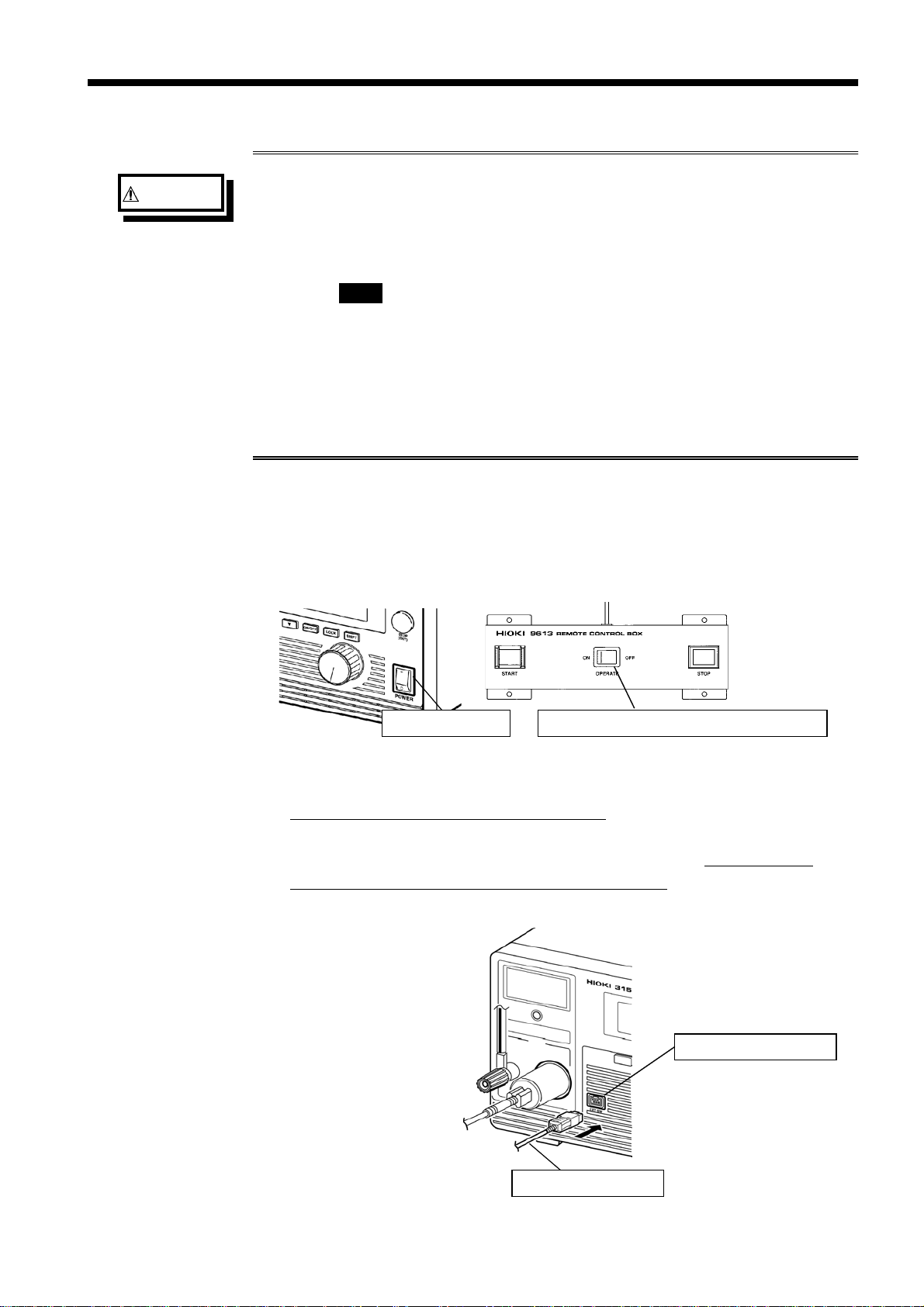
2.7 Connecting the REMOTE CONTROL BOX
・
To prevent electrical shock, turn off the power unit and tested object,
WARNING
make sure that there is no high voltage being applied to the output,
confirm the following 3 items, and connect the remote-control box.
(1) The analog voltmeter reads 0 kV.
(2) The DANGER lamp is OFF.
(3) The TEST lamp is OFF.
・
To prevent malfunctions, do not remove the REMOTE CONTROL BOX
following startup. Before removing it, be sure to turn OFF the power.
・
To avoid electric shock, when using the REMOTE CONTROL BOX,
provide safety measures to keep the output-voltage terminal, tested
object, and H.V. TEST LEAD out of contact with one another when
they are in the TEST state.
Connection of the remote-control box (9613/9614) enables start/stop operations to
be performed easily.
(1) Make sure the Main Power switch and OPERATE switch on the remote-control
box are OFF.
Main power switch OPERATE switch on the remote-control box
(2) Insert the switch signal-line plug into the external switch terminal.
Check the direction of the switch signal line.
(3) Turn ON the OPERATE switch of the remote-control box. The OPERATE
switch can be turned ON/OFF even following startup.
External switch terminal
Switch signal-line plug
────────────────────────────────────────────────────
2.7 Connecting the REMOTE CONTROL BOX
Page 27
15
────────────────────────────────────────────────────
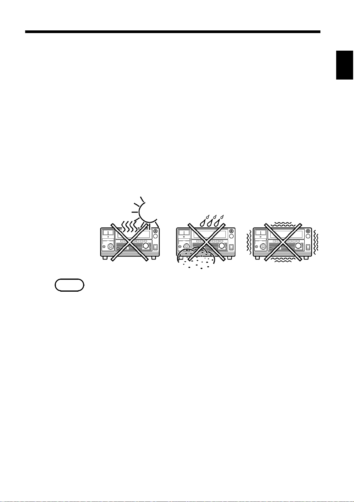
2.8 Installation of the Unit
Install the unit on a stable surface using the four rubber feet on the bottom of the
unit.
Install on a stable surface using the four stands on the bottom of the unit.
(1) Temperature 0to40℃,23±5℃recommended for high-precision
measurements.
(2) Humidity 80 %RH max. (no condensation)
(3) Avoid the following locations:
・
Subject to direct sunlight.
・
Subject to high levels of dust, steam, or corrosive gases (Avoid using the
equipment in an environment containing corrosive gases (e.g., H
and CI
cyanides, and formalins)).
・
Subject to vibrations.
・
In the vicinity of equipment generating strong electromagnetic fields.
) or substances that generate harmful gasses (e.g., organic silicones,
2
S, SO2,NI
2
2
4
,
2
5
6
7
8
NOTE
9
Noise from the unit may affect peripheral equipment.
10
11
12
13
14
A
────────────────────────────────────────────────────
2.8 Installation of the Unit
Page 28
16
────────────────────────────────────────────────────
2.9 Connection to the Measured Equipment
DANGER
To avoid any life-threatening electric shock accidents, ensure that the
following rules are observed.
・
The AC Withstanding Voltage HiTester is a dangerous product which
discharges high voltages. To prevent getting electrocuted, always
wear high-voltage protective rubber gloves when carrying out any
operation.
・
Be careful when using the product and ensure that you do not touch
this product, any tested object that is connected or any H.V. TEST
LEAD, etc.
・
Make sure that no high voltage is being applied to the output,
confirm the following items, and connect the H.V. TEST LEAD.
(1) The analog voltmeter reads 0 kV.
(2) The DANGER lamp is OFF.
(3) The TEST lamp is OFF.
・
In the TEST state, never touch the output-voltage terminal, H.V. TEST
LEAD, or tested object.
・
Even following a test, there may be a residual voltage at the output
terminal. Therefore, before touching the output-voltage terminal, H.V.
TEST LEAD, or tested object, make sure that no high voltage is being
applied between the output terminals.
NOTE
・
If the HIGH and LOW voltage output terminals short-circuit or a dielectric
breakdown occurs in the tested object during the test, noise will be generated and
such noise may lead to a malfunction of this unit or of a nearby electronic device.
If this problem occurs, connect a ferrite core or a resistor to the H. V. TEST
LEAD (high voltage side).
When using a resistor, choose one appropriate for the power rating and withstand
voltage. Also, be alert to any drop in test voltage.
Beware of electric shock when connecting the resistor.
・
Do not the test lead and the EXT/IO cable arranged closely to each other.
Doing so may lead to a ma l functio n of the external control due to a noise.
Additionally, if the test lead touches to other metallic parts, it may cause an
increase in leakage current.
Prevent the test lead from coming into contact with other parts as much as possible .
(1) Make sure the analog voltmeter is at 0 kV and the DANGER lamp is OFF, and
the TEST lamp is OFF.
(2) Connect the LOW terminal probe to the tested object. Fasten the probe securely
to prevent it from loosening during a t est.
(3) Following the procedure described above, connect the HIGH terminal probe to
the tested object.
────────────────────────────────────────────────────
2.9 Connection to the Measured Equipment
Page 29

17
────────────────────────────────────────────────────
2.10 Startup Inspection
To ensure safe testing, check the following before starting operation:
Breaking current
(1) Calculate the resistance based on the output voltage to be set and the upper level
value, and then provide a resistor suitable for the resistance.
(Output voltage÷Upper-level value (Breaking current) = Resistance)
A high-voltage resistor with a power rating larger than the power calculated
from the output voltage and resistance is recommended.
2
÷
((Output voltage)
Ex.)
For the case that the output voltage is 2 kV and the upper level value is 4 mA,
Resistance value=2 kV/4mA=0.5 M
Rated power=(2 kV)
the 16 W resistor ((Rated power) x 2)) is recommendable to leave a margin.
Resistance<Power rating)
Ω
2
/
0.5 M
Ω=
8W
Example high-voltage resistor:
KOA Corp.'s GS Series High Voltage High Resistance Thick Film Resistor
(2) Set an upper-level value.
(3) Connect the resistor to the test lead.
(4) Increase the output voltage beyond the set value, and make sure the current is
cut off (i.e., make sure the unit is in the FAIL state).
Analog voltmeter
(1) Before turning on the power, make sure the analog voltmeter is at 0 kV.
(2) If the voltage reading is not at zero, adjust the value to zero using a slotted
screwdriver.
Inter-lock
If the Inter-lock function is set, make sure the Inter-lock function works properly
before starting operation.
Key inspection
(1) Turn off the power, and unplug the power cord from the power outlet.
(2) For both the START and STOP keys on the front panel of the unit, press the
center of the key, and make sure you feel it click. The click is less noticeable
when the edges of the keys are pressed.
* Clicking
When a key is pressed slowly, there is a moment of slight resistance and a
feeling that the key cannot be pressed any further. When the key is pressed
further after this point, a clicking sensation can be felt.
(3) If you do not feel a click, the key may be broken.
────────────────────────────────────────────────────
2.10 Startup Inspection
Page 30

18
────────────────────────────────────────────────────
────────────────────────────────────────────────────
2.10 Startup Inspection
Page 31

19
────────────────────────────────────────────────────
Chapter 3
1
DANGER
Testing Method
This chapter describes the procedural flow for testing, making settings, and proper
testing procedure.
Read Chapter 2, "Testing Arrangements" and make the necessary arrangements for
testing.
SHIFT+STOP
Press
Setting the optional functions allows testing under various conditions.
For more information, see Chapter 4, "Optional Functions."
To avoid any life-threatening electric shock accidents, ensure that the
following rules are observed.
・
The AC Withstanding HiTester is a dangerous product which
discharges high voltages. To prevent getting electrocuted, always
wear high-voltage protective rubber gloves when carrying out any
operation.
・
Be careful when using the product and ensure that you do not touch
this product, any tested object that is connected or any H.V. Test
Lead, etc.
keys to display the Optional function setting screen.
3
5
6
7
8
9
10
11
NOTE
────────────────────────────────────────────────────
Note that the output waveform may be distorted when con ducting an AC
withstand voltage test for a voltage-dependent device or object (e.g., ceramic
capacitor). Excessively large distortion may damage the device or tested object.
When the device or tested object is a capacitive load, resonance may occur (when
conducting an AC withstand voltage test) with the coil inductance of the output
high-voltage transformer, depending on the capacitance value. This condition may
generate several tens of volts at the voltage output terminal before the test is
started. If the
set it bac k to the desired voltage after starting the test.
START
key is disabled, reset the output voltage knob to zero, then
12
13
14
A
Page 32

20
(1) (2) (3) (4) (5) (6) (7) (8) (9)
────────────────────────────────────────────────────
3.1 State of the 3158 and Preset Parameters
The 3158 is in one of the following five states:
READY state
「READY 状態」
Output voltage range
The unit is ready for starting a test. The READY lamp is turned on.
To enter TEST state, press the
START
Key-lock Function
key while in READY state.
Setting items
Output voltage range
Key-lock Function
Refer to 3.2.1
Refer to 3.2.2
Setting the optional functions allows testing under various conditions.
SHIFT+STOP
Press
Setting optional functions
Refer to Chapter 4
keys to display the Optional Function Setting screen.
(1) PASS Hold Function
(2) FAIL Hold Function
(3) Hold Function
(4) Momentary Out
(5) Double Action
(6) FAIL Mode
(7) RS Command
(8) Inter-lock Function
(9) Voltage Comparator
Position
SETTING state
「READY 状態」
To switch to the SETTING state, press the / keys. In this state, test
parameters can be set.
To terminate the test settings and return to the READY state, press the
STOP
Comparative voltage value
Setting items
────────────────────────────────────────────────────
3.1 State of the 3158 and Preset Parameters
key, which will finalize the settings.
Upper (Lower) level value Test time
Comparative voltage value
Upper (Lower) level value
Test time
Refer to 3.3.1
Refer to 3.3.2
Refer to 3.3.3
Page 33

21
────────────────────────────────────────────────────
"TEST" state
「READY 状態」
When the unit is in the TEST state, the TEST lamp is lit. This indicates that a test is in
progress. The measured-voltage value is compared with the comparative-voltage value set in the
SETTING state. If the measured-voltage value deviates from the comparative-voltage range, the
unit shifts to the FAIL state. The measured-current value is compared with the upper- and
lower-level values. If the measured-current value deviates from these values, the unit shifts to
the FAIL state and the test is terminated. When the preset test time has elapsed, if there have
been no deviations, the unit shifts to the PASS state.
Refer to 3.4.3
1
3
5
Key operation in the TEST status
"PASS" state
「READY 状態」
PASS indicates that the measured object passed the test set in READY state. The PASS
lamp is turned on. The PASS state screen is displayed for about 0.5 second before
switching to READY state.
The PASS state can be maintained if the PASS Hold function is disabled in the optional
settings. To return to the READY state, press the
Hold function.
"FAIL" state
「READY 状態」
READY indicates that the tested object failed to pass the test set in the READY state. The
FAIL lamp will light up, accompanied by UPPER if the measured value exceeds the upper-
level value, or by LOWER if the measured value is below the lower-level value. If the
measured value deviates from the comparative-voltage range, the FAIL lamp will light up,
accompanied by both UPPER and LOWER. The FAIL-state screen is displayed for 0.5
seconds, and the unit then switches to the READY state. The FAIL state can be maintained
if the FAIL Hold function is disabled in the optional settings. To return to the READY
state, press the
Refer to 3.5.1
Refer to 3.5.3
STOP
key, which will cancel the FAIL Hold function.
Forced ending
STOP
Press the
key, which will cancel the PASS
STOP
key.
6
7
8
9
10
11
12
13
14
────────────────────────────────────────────────────
3.1 State of the 3158 and Preset Parameters
A
Page 34

22
(1)
(2) (3)
(4)
(5)
────────────────────────────────────────────────────
3.2 Making Testing Arrangements (in READY State)
In the READY state, the unit is always ready to start a test. The unit can be shifted
to the SETTING state only when it is in the READY state.
The
READY
setting data and the setting of optional functions are made following the READY
state.
lamp remains lit to indicate READY state. Saving and loading for
(1) Measured voltage value
Indicates the voltage value being output. In the READY state, the value
indicates at 0 kV.
(2) Upper level value icon and Lower level value icon
The symbol
appears when the upper level value is set, and the symbol
appears when the lower level value is set.
(3) Upper (Lower) level value
Indicates Upper (Lower) level value.
(4) Test time
Indicates the preset test time. "OFF" is indicated when no test-time setting has
been made.
(5) Output voltage range
Indicates the output-voltage range selected using the Range Selection switch
Analog voltmeter
Indicates the voltage value being output. In the READY state, the value remains at
0 kV.
Danger lamp
Indicates that a voltage is being output. This lamp remains lit as long as a voltage
of at least 0.0 3 kV is being applied to the output terminal. It does not light up in
the READY state.
External I/O
_________
The READY
_________
The READY
────────────────────────────────────────────────────
3.2 Making Testing Arrangements (in READY State)
signal is ON when READY is lit on the fluorescent indicator.
signal is turned OFF when READY is not lit.
Page 35

23
────────────────────────────────────────────────────
3.2.1 Selecting an Output-Voltage Range
1
WARNING
The output voltage set using the output-voltage knob nearly doubles
when the output-voltage range is changed from 2.5 kV to 5.0 kV.
Conversely, if the range is changed from 5.0 kV to 2.5 kV, the output
voltage is reduced by approximately half. After changing the outputvoltage range, be sure to reset the output voltage using the outputvoltage knob.
In the READY state, change the output-voltage range (2.5 kV/5.0 kV) using the
Range Selection switch. When the output-voltage range is shifted, RANGE flickers.
This change is effective for the next test.
Flashing
3
5
6
7
8
Range Selection switch Output voltage knob
NOTE
If you turn the output-voltage knob fully clockwise, the voltage may exceed the set
output-voltage range.
3.2.2 Key-lock Function
It inactivates all keys except the
The KEYLOCK lamp is lit while the key-lock function is active.
To switch to the KEYLOCK state, press the
function, press the
SHIFT
The output-voltage set using the output-voltage knob will not become invalid.
key.
LOCK
START
key in the Key-lock state while holding down the
key,
STOP
LOCK
key, and the range switch.
key. To cancel the key-lock
9
10
11
12
13
14
NOTE
────────────────────────────────────────────────────
Even when the key-lock function is activated, the
remote control box and the signals on the external I/O terminal remain active.
3.2 Making Testing Arrangements (in READY State)
START
and
STOP
keys on the
A
Page 36

24
(1) (2) (3) (4) (5) (6) (7) (8) (9)
────────────────────────────────────────────────────
3.2.3 Initial Settings for Optional Functions
SHIFT+STOP
Press
function setting screen.
Setting the optional functions allows testing under various conditions.
Settings can be made for the following eight optional functions. One number is
assigned to each function. Settings are made by changing the number by using the
/ keys.
For more information on the settings, see Chapter 4, "Optional Functions."
keys while in READY state to display the Optional
The optional functions of the 3158 are factory-preset to the following settings:
Setting item Initial setting
(1) PASS Hold Function
(2) FAIL Hold Function
(3) Hold Function
(4) Momentary Out
(5) Double Action
(6) FAIL mode
(7) RS Command [Start]
(8) Inter-lock Function
(9) Voltage Comparator Position
0: PASS not held
1: FAIL held
0: Not held
0: Not set
0: Not set
0: Not set
0: Not set
0: Not set
0: Start test
────────────────────────────────────────────────────
3.2 Making Testing Arrangements (in READY State)
Page 37

25
────────────────────────────────────────────────────
3.3 Setting the "SETTING" State
To change settings, switch to the SETTING state. In the READY state, press the
/ keys. The flashing cursor will then appear at the position where the
comparative voltage is indicated to show that the unit is in the SETTING state. The
READY light will go out. In the SETTING state, a test will not start even if the
START
the READY state.
key is pressed. To start a test, complete the test settings and then return to
1
3
Voltage measurement value
READY state
READY
SETTING state
試験設定状態
■
Setting procedure
In the SETTING state, set test values while moving the flashing cursor using the
The flashing cursor will move between the comparative-voltage value, the upperlevel value, the lower-level value, and the test time, in that order. If the value
indicated by the flashing cursor is not needed in the test, turn it OFF using the
ON/OFF
状態
Comparative voltage value
/ keys.
key. The upper-level value, however, cannot be turned OFF.
5
6
7
8
9
10
In the SETTING state, a test will not start even if the
finalize the test settings, press the
READY state. Note that the unit will not return to the READY state if the set
lower-level value is greater than the upper-level value. In such a case, correct the
settings and then press the
NOTE
────────────────────────────────────────────────────
A voltage being measured is displayed in the READY sate. In the SETTING state,
the comparative voltage value is displayed. Note that the display of the comparative
voltage value does not mean that the voltage is being output.
STOP
STOP
keytoreturntotheREADYstate.
key, which will return the unit to the
START
3.3 Setting the "SETTING" State
keyispressed.To
11
12
13
14
A
Page 38

26
────────────────────────────────────────────────────
3.3.1 Setting the Comparative Voltage Value
If a comparative-voltage value is to be set, value settings must be made. Once a
comparative-voltage value is set, a test will not start until the output voltage reaches
the comparative-voltage r ange, which is±5% of the comparative-voltage value
(output voltage:≦1kV:±50 V). TEST will flicker until the value reaches the
value range. If the value fails to reach the value range within approximately five
seconds, FAIL will light along with UPPER and LOWER and the test will quit
with the FAIL judgment. Also, in the same way the test will quit with the FAIL
judgment if it is outside of the standard voltage range during the test. If a
comparative-voltage value is not to be used, press the
ON/OFF
setting for that value OFF. Any voltage value can then be output in the TEST state.
key to turn the
Comparative voltage value: 3.50 kV
Comparative voltage value: OFF
(1) If no flashing cursor is displayed in the READY state, press either the
/
key to display the cursor while the comparative voltage value is l it.
(2) Change the comparative voltage value using the
changes in 0.01 kV increments. To change the value by 0.10 kV, press
/ keys. The value
SHIFT
+ / keys.
The comparative voltage value can be set from 0.00 kV to 5.00 kV.
If a comparative voltage value is not to be used, press the
ON/OFF
key to turn
the setting for that value OFF.
(3) When settings are complete, press the
(4) In the READY state, press the
START
STOP
key.
key to output the measured voltage. If
the value fails to reach the value range within approximately five seconds, the
unit returns to the READY state. During those five seconds, use the outputvoltage knob to set the output voltage to the comparative-voltage value.
(5) When the output voltage is equal to the comparative-voltage value, terminate the
settings for the comparative-voltage value.
NOTE
If the test time is set to OFF, the settings for the comparative-voltage value will
become invalid. Therefore, when the output-voltage settings are made, it is advisable
to set the test time to OFF.
You can select whether you want to check the output-voltage when the test starts or ends.
・
(Starting a test with default settings:) (See Section 4.9)
────────────────────────────────────────────────────
3.3 Setting the "SETTING" State
Page 39

27
────────────────────────────────────────────────────
3.3.2 Setting the Upper (Lower) Level Value
Upper (Lower) level value: 20 mA
(1) If the flashing cursor does not appear in the READY state, display the cursor at
the position where the Upper-Level Value (Lower-Level Value) is indicated by
pressing the
(2) Set the upper (lower) level value using the
The upper (lower)-level value will change by 0.1 mA (by 1 mA at 10 mA to 120
mA). While holding down the
(lower)-level value will change by 1.0 mA (by 10 mA at 10 mA to 120 mA).
If no lower level value is required, turn off the
can not be turn off.
(3) When settings are complete, press the
/ keys.
SHIFT
/ keys.
key, press the / keys. The upper
STOP
ON/OFF
key.
key. Upper level value
1
3
5
6
7
NOTE
Lower level value: 1.0 mA
Lower level value: OFF
・
The setting resolution of the upper (lower)-level value is 0.1 mA at 0.1 mA to 9.9
mA, and 1 mA at 10 mA to 120 mA.
・
The current measurement resolution during a test depends on the set upper-level
value: 0.01 mA at 0.1 mA to 8.0 mA, 0.1 mA at 8.1 mA to 32 mA, and 1 mA at
33 mA to 120 mA.
・
If the set lower-level value is greater than the upper-level value, the unit will not
return to the READY state even when the
correct the upper- or lower-level value.
・
The electric current range will be decided by the upper-limit test value (2 mArange for "upper-limit test value≦2.0 mA", 8 mA-range for "2.0 mA<upperlimit test value≦8.0 mA", 32 mA-range for "8.0mA<upper-limit test value≦32
mA", 120 mA-range for "32 mA<upper-limit test value")
STOP
key is pressed. In such a case,
8
9
10
11
12
13
14
A
────────────────────────────────────────────────────
3.3 Setting the "SETTING" State
Page 40

28
────────────────────────────────────────────────────
3.3.3 Setting the Test Time
Test Time: 60.0s
Test Time: OFF
NOTE
(1) If the flashing cursor does not appear in the READY state, display the cursor at
the position where the Test Time is indicated by pressing the
(2) Set the test time using the
/ keys.
/ keys.
With time set the time changes in 0.1 s increments (1 s increments when the set
time scale is 100 s to 999 s).
With time set at 0.5 s to 9 9.9 s, press
SHIFT
+ / keys. The time
changes in 1.0 s increments (10 s increments when the set time scale is 100 s to
999 s).
Settings may be made along a scale ranging from 0.5 s to 999 s (in gradations of
0.1 s for the range 0.5 s to 99.9 s and 1 s for the range 100 s to 999 s).
If no testing time is required, turn off the
(3) When settings are complete, press the
・
If a test time has been set, the reduction timer will operate during the test.
・
If the test time is set to OFF, the time elapsed during the test is displayed. When
ON/OFF
STOP
key.
key.
this time exceeds 999 s, "_" will appear, but the test will continue.
・
If the test time is set to OFF, the comparative-voltage value becomes ineffective.
────────────────────────────────────────────────────
3.3 Setting the "SETTING" State
Page 41

29
────────────────────────────────────────────────────
3.3.4 Examples of Settings
NOTE
The settings immediately prior to power shutdown are saved. The unit restarts with
these settings, even following a power interruption. When settings are modified,
however they are only saved after running a test.
The following shows an example of a test at a comparative-voltage value of 2.00 kV
and an upper-level value of 20 mA, with the lower-level value set to OFF, at a test
time of 60.0 s. The 3158 is in the READY state.
Values currently set
Comparative voltage
value
Upper level value 120 mA Upper level value 20 mA
Lower level value 40 mA Lower level value OFF
Test time 120 s Test time 60.0 s
OFF Comparative voltage
Values to be set
2.00 kV
value
(1) Changing to the SETTING state
Press the / keys to switch to the SETTING state. The READY light will
go out, and the flashing cursor will be displayed at the position where the
comparative-voltage value is indicated.
In the READY state, a measured-voltage value is displayed. In the SETTING
state, the display changes to the comparative-voltage value (in this example,
OFF).
────────────────────────────────────────────────────
3.3 Setting the "SETTING" State
Page 42

30
────────────────────────────────────────────────────
(2) Setting the comparative-voltage value
The comparative-voltage value is initially set to OFF. It must be changed to ON
before the value is changed. To do so, press the
ON/OFF
key.
The comparative-voltage value in the OFF state is displayed. In this example,
the value is 1.50 kV.
Using the
To change the value by 0.01 kV, press
To change the value by 0.10 kV, press
/ keys, set the comparative voltage value to 2.0 0 kV.
/ keys.
SHIFT
+ / keys.
(3) Setting an upper-level value
Press the
key to move the flashing cursor to the upper-level value.
In this example, switch from 120 mA to 20 mA using the
To change the upper level value by 1 mA, press
To change the upper level value by 10 mA, press
(4) Setting a lower-level value
Using the
key, move the flashing cursor to the lower level value.
/ keys.
SHIFT
/ keys.
+ / keys.
────────────────────────────────────────────────────
3.3 Setting the "SETTING" State
Page 43

31
────────────────────────────────────────────────────
The lower-level value is set at 40 mA. Turn it OFF, as it is not needed. To
change to OFF, press the
ON/OFF
key.
(5) Setting the test time
Using the
key, move the flashing cursor to the test time.
In this example, change the test time from 120 s to 60.0 s.
(6) Changing to the READY state
To conduct a test using these settings, switch to the READY state. To return to
the READY state, press the
STOP
key, which will finalize the test settings. In
the READY state, the displayed comparative-voltage value is replaced with a
measured-voltage value, and READY lights up.
The new parameters following setting are shown below:
Comparative voltage value 2.00 kV
Upper level value 20 mA
Lower level value OFF
Test time 60.0 s
Press the
START
key while in this state. The unit enters TEST state to begin
testing.
────────────────────────────────────────────────────
3.3 Setting the "SETTING" State
Page 44

32
────────────────────────────────────────────────────
3.4 Starting a Test
The flowchart below explains how a test is carried out.
Setting the "READY"state
READY
「
状態」での設定
Output Voltage Range
Refer to 3.2.1
Key-lock Function
Optional Function
Setting the "SETTING"state
Comparative Voltage Value
Upper (Lower) level value
Test Time
Setting the "Output voltage"
READY
「
Before starting a test, make output voltage settings using the output-voltage knob.
A voltage is output during output-voltage setting using the output-voltage knob. Never touch the HIGH
terminal, test lead, or tested object.
Starting a Test
READY
「
Press the
TEST and the DANGER lamp are lit in the TEST state.
If a comparative-voltage value has been set, the test will not start until the output voltage is within±5%
of the comparative-voltage value (output voltage:≦1 kV:±50 V).
状態」での設定
状態」での設定
START
key when READY is lit. The unit will change to the TEST status and a test will start.
Refer to 3.4.1
Refer to 3.4.2
Refer to 3.2.2
Refer to Chapter 4
Refer to 3.3.1
Refer to 3.3.2
Refer to 3.3.3
Determination
READY
「
状態」での設定
Refer to 3.5
PASS/FAIL screening is conducted based on whether a measured-current value exceeds the
upper- or lower-level value. The test is failed (FAIL) if, with a comparative-voltage value set, the
output-voltage value fails to reach the comparative-voltage range within 5 seconds after the
START
key is pressed, or if the output-voltage value deviates from the comparative-voltage
range.
────────────────────────────────────────────────────
3.4 Starting a Test
Page 45

33
────────────────────────────────────────────────────
3.4.1 Setting the Output Voltage
DANGER
To avoid any life-threatening electric shock accidents, ensure that the
following rules are observed.
・
The AC Withstanding HiTester is a dangerous product which
discharges high voltages. To prevent getting electrocuted, always
wear high-voltage protective rubber gloves when carrying out any
operation.
・
Be careful when using the product and ensure that you do not touch
this product, any tested object that is connected or any H.V. Test
Lead, etc.
・
Make sure that no high voltage is being applied to the output,
confirm the following items, and output voltage.
(1) The analog voltmeter reads 0 kV.
(2) The DANGER lamp is OFF.
(3) The READY lamp is lit (it is off in the Double Action mode).
・
A voltage is output during output-voltage setting using the
outputvoltage adjustment knob. Never touch the HIGH terminal, H.V.
TEST LEAD, or tested object.
Before starting a test, make output voltage settings using the output-voltage knob . If
a comparative-voltage value has already been set, press the
output voltage within 5 seconds after pressing the
successful, the test switches to the FAIL state.
START
START
key. If the setting is not
key and set an
(1) In accordance with the instructions given in 2.9, "Connection to the Measured
Equipment," connect the probe to the tested object.
(2) Make sure the analog voltmeter is at 0 kV, the DANGER lamp is OFF, and the
unit is in the READY state.
(3) Set the output-voltage range using the Range Selection switch.
(4) Press the
(5) Set an output voltage using the output-voltage knob. The output-voltage knob
increases the output voltage when turned clockwise, and decreases the voltage
when turned counterclockwise. The maximum value is 2.5 kV or 5.0 kV,
depending on the output-voltage range set in Step (3). The output voltage is
displayed on the analog voltmeter and the fluorescent indicator.
(6) Upon completion of the output-voltage settings, press the
output.
START
key. TEST will light up and a voltage will be output.
STOP
key to stop the
────────────────────────────────────────────────────
3.4 Starting a Test
Page 46

34
────────────────────────────────────────────────────
Set an output voltage using
the output-voltage knob.
Range Selection Switch Output voltage knob
NOTE
If you turn the output-voltage knob fully clockwise, the voltage may exceed the set
output-voltage range.
■
Rated time for output voltages (at an ambient temperature of 40℃)
The transformer capacity of the unit is approximately half the rated output. Use the
unit within the rated time. If the rated time is exceeded, the un it may overheat and
thereby cause the thermal fuse for the internal circuit to blow out.
Current measurement range Maximum test time Pause
I ≦60 mA Continuous None
60 mA < I ≦100 mA 30 minutes 30 minutes
100 mA < I ≦ 120 mA 10 minutes 30 minutes
・
NOTE
If the test time is set to OFF, the comparative-voltage value becomes ineffective,
thereby facilitating output-voltage adjustments.
・
The output-voltage range can only be changed in the READY state. The range
cannot be changed in other states, even using the Range Selection switch.
The Double Action increases the safety of testing by preventing operational errors.
Refer to Section 4.5 Double Action
────────────────────────────────────────────────────
3.4 Starting a Test
Page 47

35
────────────────────────────────────────────────────
3.4.2 Executing a Test
DANGER
To avoid any life-threatening electric shock accidents, ensure that the
following rules are observed.
・
The AC Withstanding HiTester is a dangerous product which
discharges high voltages. To prevent getting electrocuted, always
wear high-voltage protective rubber gloves when carrying out any
operation.
・
Be careful when using the product and ensure that you do not
touch this product, any tested object that is connected or any H.V.
Test Lead, etc.
・
Make sure that no high voltage is being applied to the output,
confirm the following items, and output voltage.
(1) The analog voltmeter reads 0 kV.
(2) The DANGER lamp is OFF.
(3) The READY lamp is lit (it is off in the Double Action mode).
・
A voltage is output during output-voltage setting using the
outputvoltage adjustment knob. Never touch the HIGH terminal,
H.V. TEST LEAD, or tested object.
・
When the
on the analog voltmeter and the fluorescent indicator is being
output. Never touch the HIGH terminal, test lead, or tested object.
and DANGER lamps are lit, the voltage displayed
TEST
CAUTION
NOTE
・
For output, the unit uses a high-voltage transformer that boosts the
power voltage. If an unstable power voltage is used to operate the unit,
the tested object may be damaged by the distortion of the output-voltage
waveform and by the output of a voltage higher than the preset voltage.
・
If a capacity load is applied to the tested object, the output voltage may
exceed the preset voltage, thereby damaging the equipment.
・
Continuous output of a high voltage may heat the bottom of the unit.
Take special care when handling the unit (e.g. transporting the unit).
Priority for control of the
the START switch on the REMOTE CONTROL BOX, the external I/O, and the
front panel of the unit. Connecting the switch signal line plug on the REMOTE
CONTROL BOX disables the
start signal for the external I/O.
(1) Press the
status and a test will start. TEST and the DANGER lamp are lit in the TEST
state.
(2) If a comparative-voltage value has been set, the test will not start until the
output voltage is within±5% of the comparative-voltage value (output voltage:
≦
1kV:±50 V).
START
START
key when READY is lit. The unit will change to the TEST
key is in the following order:
START
key on the front panel of the unit and the
────────────────────────────────────────────────────
3.4 Starting a Test
Page 48

36
────────────────────────────────────────────────────
(3) In a test with a comparative-voltage value set, the test is forcibly terminated
when the output voltage deviates by±5% from the comparative-voltage value
(output voltage:≦1kV:±50 V). In such a case, UPPER, LOWER,and
FAIL will light up. Reset the output voltage and restart the test.
To terminate the test, press the
STOP
key. The unit will immediately stop
outputting a voltage and switch to the READY state. In such a case, no screening is
conducted.
The Hold function can be used to hold the value that was effective at the time of forced
・
termination of the test. Refer to Section 4.3 Hold Function.
When a comparative-voltage value is set, the FAIL Hold function enables the unit to forcibly
・
terminate the test when the output voltage deviates from the comparative-voltage range. The
most recently set value is held. Refer to Section 4.2 FAIL Hold Function.
You can select whether you want to check the output-voltage when the test starts or ends.
・
(Starting a test with default settings:) Refer to Section 4.9 Voltage Comparator Position
The Double Action increases the safety of testing by preventing operational errors.
・
Refer to Section 4.5 Double Action
────────────────────────────────────────────────────
3.4 Starting a Test
Page 49

37
(1)
(2) (3)
(4)
(5)
────────────────────────────────────────────────────
3.4.3 Screening in "TEST State"
(1) Measured voltage value
Indicates the voltage value being output.
(2) Upper level value icon and Lower level value icon
The symbol
appears when the upper level value is set, and the symbol
appears when the lower level value is set.
(3) Measured current value
Represent the value of a current flowing between the HIGH a nd LOW terminals.
(4) Test time elapsed
When the testing time is set, countdown starts from the time set, and is
displayed. When the testing time is set to OFF, the time elapsed after the start
of the test is displayed.
If the elapsed test time exceeds 999 s, "_" is displayed, but the voltage
continues to be output.
(5) Output voltage range
Indicates the output-voltage range selected using the Range Selection switch
(6) TEST
Remains lit during the test. TEST flickers for up to five seconds at the start of a
test and when the output voltage exceeds the comparative-voltage range.
Analog voltmeter
Indicates the voltage value being output.
Danger lamp
Indicates that a voltage is being output. This lamp remains lit as long as a voltage
of at least 0.0 3 kV is being applied to the output terminal. It does not light up in
the READY state.
External I/O
_______
The TEST
_________
The H.V.ON
signal is turned ON when TEST on the fluorescent indicator lights up.
signal is turned on when the DANGER lamp lights up. The two
signals are turned OFF at the same time. At the start of a test, the unit waits for up
to five seconds for the output voltage to switch to the comparative-voltage range.
During this period, TEST flickers but the TEST
________
L-FAI L
signals are turned ON when the output-voltage value deviates from the
_______
_________
signal is ON. The U-FAIL
and
comparative-voltage value range when UPPER, LOWER,andFAIL are lit.
────────────────────────────────────────────────────
3.4 Starting a Test
Page 50

38
g
p
g
────────────────────────────────────────────────────
3.5 PASS or FAIL Determination
3.5.1 "PASS" State
WARNING
Even when a test has been terminated, there may still be voltage in
the output-voltage terminal when the DANGER lamp is lit. Before
touching the output-voltage terminal, test lead, or tested object, make
sure the analog voltmeter is at 0 kV, the DANGER lamp is OFF, and
the TEST lamp is OFF.
When the preset test time has elapsed, the unit switches to the PASS state and
immediately stops outputting a voltage. If the test time has not been set, PASS
screening is not performed. To the test, press the
STOP
key, which will forcibly
terminate the test.
The PASS state is held using the PASS Hold function.
・
Refer to Section "4.1 PASS Hold Function".
■
Flow of PASS determination
Output voltage
Comparative
volta
evalue
Testingtime when it set u
Time
Flashin
(1) Press the
START
key to start a test.
(2) If a comparative-voltage value has been set, TEST flickers until the output
voltage switches to the comparative-voltage range. When the output voltage
switches to that range, TEST remains lit and the reduction timer begins
counting down the test time.
(3) A voltage is output until the test time elapses. (If the measured-current value deviates
from the upper- and lower -le vel values , the unit switches to the FAIL state.
(4) When the preset test time has elapsed, the unit stops outputting a voltage and
switches to the PASS state. PASS lights up in the PASS state.
NOTE
If a comparative-voltage has not been set, TEST does not flicker.
If the optional "Voltage Comparator Position" function is set to "1: End of test
time", TEST does not flicker.
────────────────────────────────────────────────────
3.5 PASS or FAIL Determination
Page 51

39
(1)
(2) (3)
(4)
(5)
(6)
────────────────────────────────────────────────────
3.5.2 Screening in "PASS" State
(1) Measured voltage value
Indicates the voltage in the PASS state.
(2) Upper level value icon and Lower level value icon
The symbol
appears when the upper level value is set, and the symbol
appears when the lower level value is set.
(3) Measured current value
Indicates the value of the current flowing between the HIGH a nd LOW terminals
in the PASS state.
(4) Test completion time
Displays the time in which the test has been completed. In PASS state, 0.0s is
displayed.
(5) Output voltage range
Indicates the output-voltage range selected using the Range Selection switch.
(6) PASS
Indicates that the unit is in the PASS state.
Analog voltmeter
Indicates the voltage being output. The PASS Hold function cannot be used on the
analog voltmeter.
Danger lamp
Indicates that a voltage is being output. This lamp remains lit as long as a voltage
of at least 0.0 3 kV is being applied to the output terminal. It does not light up in
the READY state.
External I/O
_______
The PASS
long as the PASS state is held, the PASS
turned OFF when the
remains in the output-voltage terminal following termination of a test, the H.V.ON
signal remains ON. When the DANGER lamp goes out, the H.V.ON
signal is turned ON when PASS on the fluorescent indicator is lit. As
PASS
_______
signal remains ON. The PASS
light on the fluorescent indicator goes out. If voltage
_______
signal is
_________
_________
signal is
immediately turned OFF.
────────────────────────────────────────────────────
3.5 PASS or FAIL Determination
Page 52

40
────────────────────────────────────────────────────
3.5.3 "FAIL" State
WARNING
Even when a test has been terminated, there may still be voltage in
the output-voltage terminal when the DANGER lamp is lit. Before
touching the output-voltage terminal, test lead, or tested object, make
sure the analog voltmeter is at 0 kV, the DANGER lamp is OFF, and
the TEST lamp is OFF.
If the measured voltage deviates from the upper- or lower-level value during the test,
the unit switches to the FAIL state and immediately stops outputting a voltage. The
FAIL state can be divided into UPPER FAIL and LOWER FAIL states.
・
UPPER FAIL indicates that the measured voltage has exceeded the upper-level
value.
・
LOWER FAIL indicates that the measured voltage has dropped below the lowerlevel value.
(When the lower-level value is set to OFF, LOWER FAIL is ineffective.)
With a comparative voltage value set, if the output voltage deviates from the
comparative-voltage range, the unit switches to the FAIL state and UPPER,
LOWER,andFAIL light up.
The FAIL state is held using the FAIL Hold function. Refer to Section "4.2 FAIL Hold Function".
・
────────────────────────────────────────────────────
3.5 PASS or FAIL Determination
Page 53

41
g
)
p
g
────────────────────────────────────────────────────
Flow of FAIL determination
Output voltage
Comparative
volta
evalue
Testingtime when it set u
Time
NOTE
(1) Press the
START
Flashin
key to start a test.
UPPER/LOWER
(2) When a comparative-voltage value has been set, TEST flickers until the output
voltage switches to the comparative-voltage range. Once the output voltage
switches to this range, TEST lights up and the reduction timer begins counting
down the test time.
(3) A voltage continues to be output until the test time elapses. If the measured
current deviates from the upper- or lower-level value during this period, the unit
switches to the FAIL state.
(4) Once a switch is made to the FAIL state, FAIL lights up, together with UPPER
or LOWER. The unit stops outputting a voltage and the reduction timer stops.
・
If the current generated is several times as large as the upper-level value, for
example when the test object is short-circuited and etc., a circuit promptly cuts
off the high voltage, thereby switching the unit to UPPER FAIL before measuring
the current.
・
If a comparative-voltage has not been set, TEST does not flicker.
If the optional "Voltage Comparator Position" function is set to "1: End of test
time", TEST does not flicker.
────────────────────────────────────────────────────
3.5 PASS or FAIL Determination
Page 54

42
g
g
A
g
p
g
────────────────────────────────────────────────────
FAIL Screening Using the Comparative-Voltage Value
Output voltage
Comparative
volta
evalue
pproximately 5 seconds
Time
Flashin
(1) Press the
START
key to start a test.
(2) TEST will flicker until the output voltage switches to the comparative-voltage
range.
(3) If the output voltage fails to switch to this range in 5 seconds, the unit switches
to the FAIL state and stops outputting a voltage.
(4) In the FAIL state, UPPER, LOWER,andFAIL light up to indicate that an
improper voltage has been output.
Output voltage
Comparative
volta
evalue
Testingtime when it set u
Time
Flashin
(1) Press the
START
key to start a test.
(2) TEST will flicker until the output voltage switches to the comparative-voltage
range. When the output voltage switches to this range, TEST lights up and the
subtraction timer begins counting down the test time.
(3) If the output voltage deviates from the comparative-voltage range during the test,
the unit immediately stops outputting a voltage and the test is terminated.
(4) In the FAIL state, UPPER, LOWER,andFAIL light up to indicate that an
improper voltage has been output.
NOTE
・
If the optional "Voltage Comparator Position" function is set to "1: End of test
time", since the unit shifts to the TEST state whenever voltage is output, TEST
does not flash before the output-voltage value reaches the comparative-voltage
value range.
・
If the optional "Voltage Comparator Position" function is set to "1: End of test
time", this function checks whether the output voltage is within the standard
voltage range only when the test is terminated.
────────────────────────────────────────────────────
3.5 PASS or FAIL Determination
Page 55

43
(1)
(2) (3)
(4)
(5)
(6)
────────────────────────────────────────────────────
3.5.4 Screening in "FAIL" State
(1) Measured voltage value
Indicates the voltage in the FAIL state
(2) Upper level value icon and Lower level value icon
The symbol
appears when the upper level value is set, and the symbol
appears when the lower level value is set.
(3) Measured current value
Indicates the current flowing between the HIGH and LOW terminals in the FAIL
state
(4) Test completion time
Indicates the time when the unit switched to the FAIL state. If the test time has
been set, the remaining test time is displayed. If the test time is set at OFF, the
period of time during which a voltage is output is displayed.
(5) Output voltage range
Indicates the output-voltage range selected using the Range Selection switch
(6) FAIL
Indicates that the unit is in the FAIL state. FAIL lights up with UPPER to
indicate UPPER FAIL, and with LOWER to indicate LOWER FAIL. If the
output voltage deviates from the comparative-voltage range and switches the
unit to the FAIL state, UPPER, LOWER,andFAIL light up.
Analog voltmeter
Indicates the voltage being output. The analog voltmeter is not held even if the
FAIL Hold function is disabled.
Danger lamp
Indicates that a voltage is being output. This lamp remains lit as long as a voltage
of at least 0.0 3 kV is being applied to the output terminal. It does not light up in
the READY state.
External I/O
_________
The U-FAIL
fluorescent indicator. If the output voltage deviates from the comparative-voltage
range, both the U-FAIL
_________
L-FAIL
_________
L-FAIL
signals remain ON as long as the FAIL state is held. The U-FAIL
signal are turned OFF when the FAIL light on the fluorescent indicator
goes out. If voltage remains in the output-voltage terminal following the termination
of a test, the H.V.ON
_________
H.V.ON
signal is immediately turned OFF.
_________
or L-FAI L
_________
_________
signal is turned ON when FAIL lights up on the
_________
and L-FAIL
signals are turned ON. Both the U-FAIL
_________
_________
and
and
signal remains ON. When the DANGER lamp goes out, the
────────────────────────────────────────────────────
3.5 PASS or FAIL Determination
Page 56

44
────────────────────────────────────────────────────
────────────────────────────────────────────────────
3.5 PASS or FAIL Determination
Page 57

45
────────────────────────────────────────────────────
Chapter 4
Optional Functions
1
2
4
5
6
7
8
9
10
11
12
13
────────────────────────────────────────────────────
14
A
Page 58

46
(1) (2) (3) (4) (5) (6) (7) (8) (9)
────────────────────────────────────────────────────
Setting the optional functions allows testing under various conditions.
Settings can be made for the following eight optional functions. One number is
assigned to each function. Settings are made by changing the number by moving
the cursor key.
Since improper settings can produce inaccurate results, this chapter explains the
correct way to make settings. Please read it carefully.
Entering the Optional function setting screen
SHIFT+STOP
Press
function setting screen.
keys while in READY state to display the Optional
Setting optional functions
Use the / keys to move the flashing cursor to the target function.
Use the
To complete the optional settings, press
the READY state.
Press the
state without finalizing settings.
The following describes the numbers corresponding to the functions. For additional
information, see Appendix 4, "Table of Optional Functions."
(1) PASS Hold Function
This function retains PASS state to help verify the value screened in the test.
Selection
(2) FAIL Hold Function
This function retains FAIL state to help verify the value screened in the test.
Selection
(3) Hold Function
Enable this function to hold the current state when testing is interrupted by the
STOP
/ keys to set a value at the flashing cursor location.
SHIFT+STOP
STOP
key to abort the setting process. The unit reverts to the READY
0: Not held (initial setting) 1: Held
0: Not held 1: Held (initial setting)
key.
keys. The unit reverts to
Selection
0: Not held (initial setting) 1: Held
(4) Momentary Out
The momentary OUT function allows current output only while the
held down.
The
START
key on the remote control or the START signal via external I/O has
the same effect.
Selection
────────────────────────────────────────────────────
0: Not set (initial setting) 1: Set
START
key is
Page 59

47
────────────────────────────────────────────────────
(5) Double Action
Enable this function to allow testing to start only when the
within about 0.5 seconds after the
Selection
(6) FAIL Mode
Enable this function to restrict hold release to the
Selection
(7) RS Command [START]
Turn this function on to enable the RS-232C START command.
Selection
(8) Inter-lock Function
Enable this function to activate the external I/O interlock terminals.
Selection
(9) Voltage Comparator Position
When the voltage comparator is set to ON for a withstand voltage test, select
whether you want to use the voltage comparator when starting and during the test,
or only when terminating the test.
0: Not set (initial setting) 1: Set
0: Not set (initial setting) 1: Set
0: Not set (initial setting) 1: Set
0: Not set (initial setting) 1: Set
STOP
key.
STOP
START
key on the main unit.
key is pressed
1
2
4
5
6
7
Selection
0: Start test (initial setting) 1: End test
8
9
10
11
12
13
────────────────────────────────────────────────────
14
A
Page 60

48
────────────────────────────────────────────────────
4.1 PASS Hold Function
This function retains the value for the PASS state on test completion.
To inactivate the hold function, press the
STOP
READY state.
If the PASS hold function is not selected, the test result is displayed for about 0.5
second before the unit reverts to the READY state.
Setting procedure
key. The unit reverts to the
(1) Press
SHIFT+STOP
keys while in READY state to display the Optional
function setting screen.
(2) Use the
/ keys to move the flashing cursor to the position shown in the
figure.
(3) Use the
/ keys to set a value at the flashing cursor location.
0: Not held (Initial setting)
1: Held
(4) To complete the optional settings, press
reverts to the READY state.
SHIFT+STOP
keys. The unit
────────────────────────────────────────────────────
4.1 PASS Hold Function
Page 61

49
────────────────────────────────────────────────────
4.2 FAIL Hold Function
1
This function retains the value for the FAIL state on test completion.
To inactivate the hold function, press the
READY state.
If the FAIL hold function is not selected, the test result is displayed for about 0.5
second before the unit reverts to the READY state.
Setting procedure
(1) Press
(2) Use the
(3) Use the
SHIFT+STOP
function setting screen.
/ keys to move the flashing cursor to the position shown in the
figure.
/ keys to set a value at the flashing cursor location.
0: Not held
1: Held (Initial setting)
keys while in READY state to display the Optional
STOP
key. The unit reverts to the
2
4
6
7
8
(4) To complete the optional settings, press
reverts to the READY state.
SHIFT+STOP
9
keys. The unit
10
11
12
13
14
A
────────────────────────────────────────────────────
4.2 FAIL Hold Function
Page 62

50
────────────────────────────────────────────────────
4.3 Hold Function
Enable this function to hold the current state when testing is interrupted by the
STOP
To inactivate the hold function, press the
READY state.
If the Hold function is not selected, the unit switches to the READY state upon
forced termination of the test.
key.
STOP
key. The unit reverts to the
(1) Press
SHIFT+STOP
keys while in READY state to display the Optional
function setting screen.
(2) Use the
/ keys to move the flashing cursor to the position shown in the
figure.
(3) Use the
/ keys to set a value at the flashing cursor location.
0: Not held (Initial setting)
1: Held
(4) To complete the optional settings, press
reverts to the READY state.
SHIFT+STOP
keys. The unit
────────────────────────────────────────────────────
4.3 Hold Function
Page 63

51
────────────────────────────────────────────────────
Distinction between the PASS Hold Function, FAIL Hold Function, and
■
Hold Function
・
With a comparative-voltage value set, if the output voltage deviates from the
comparative-voltage range, the unit switches to the FAIL state.
・
If the test time is set to OFF, PASS screening is not performed. In such a case,
FAIL screening is performed or the test is terminated using the
Press the
START
key to start a test.
STOP
key.
1
2
3
Press the
The output voltage deviates from
the comparative-voltage range
Test time elapses.
STOP
determination
determination
key to abort a test. Hold function
OFF OFF
OFF
4
ON
6
7
8
9
FAIL HoldPASS Hold
10
ON ON
Press the
────────────────────────────────────────────────────
STOP
key to inactivate the hold function.
4.3 Hold Function
11
12
13
14
A
Page 64

52
────────────────────────────────────────────────────
4.4 Momentary Out
The momentary out function allows current output only while the
held down. Releasing the
START
key is equivalent to pressing the
and ends the test.
To perform PASS/FAIL screening, hold down the
START
time elapses.
The
START
key on the remote control or the START signal via external I/O has
the same effect.
Setting procedure
(1) Press
SHIFT+STOP
keys while in READY state to display the Optional
function setting screen.
(2) Use the
/ keys to move the flashing cursor to the position shown in the
figure.
(3) Use the
/ keys to set a value at the flashing cursor location.
START
STOP
key is
key
key until the preset test
NOTE
0: Not set (Initial setting)
1: Set
(4) To complete the optional settings, press
SHIFT+STOP
keys. The unit
reverts to the READY state.
Priority for control of the
START
key is in the following order: the switch on the
REMOTE CONTROL BOX, the external I/O, and the front panel of the unit.
────────────────────────────────────────────────────
4.4 Momentary Out
Page 65

53
────────────────────────────────────────────────────
4.5 Double Action
1
If the Double Action function is set, READY will not light up in the READY state.
READY only lights up for approximately 0.5 seconds after the
pressed. While READY is lit, press the
Action function is set, the
increases the safety of testing by preventing operational errors.
Setting procedure
(1) Press
(2) Use the
(3) Use the
SHIFT+STOP
function setting screen.
/ keys to move the flashing cursor to the position shown in the
figure.
/ keys to set a value at the flashing cursor location.
STOP
keys while in READY state to display the Optional
START
key must be pressed once. Thus, this function
key to start a test. If the Double
STOP
key is
2
4
6
7
8
NOTE
0: Not set (Initial setting)
1: Set
(4) To complete the optional settings, press
reverts to the READY state.
The Double Action function can be set in combination with the Momentary-Out
function. If settings are made in this way, press the
after the
the test.
STOP
key is pressed to start a test. Hold down the
SHIFT+STOP
START
keys. The unit
key within 0.5 seconds
START
key during
9
10
11
12
13
14
────────────────────────────────────────────────────
4.5 Double Action
A
Page 66

54
────────────────────────────────────────────────────
4.6 FAIL Mode
Enable this function to restrict hold release to the
Setting procedure
(1) Press
SHIFT+STOP
keys while in READY state to display the Optional
function setting screen.
(2) Use the
/ keys to move the flashing cursor to the position shown in the
figure.
(3) Use the
/ keys to set a value at the flashing cursor location.
0: Not set (Initial setting)
1: Set
STOP
key on the main unit.
(4) To complete the optional settings, press
reverts to the READY state.
SHIFT+STOP
keys. The unit
────────────────────────────────────────────────────
4.6 FAIL Mode
Page 67

55
────────────────────────────────────────────────────
4.7 RS Command [START]
When RS-232C is used for control, settings can be made to specify whether to
accept the test start command ":STAR."
If "1: Set" is selected, a test is started when the ":STAR" c ommand is received.
If "0: Not set" is selected, this command is disregarded.
Setting procedure
NOTE
(1) Press
SHIFT+STOP
keys while in READY state to display the Optional
function setting screen.
(2) Use the
/ keys to move the flashing cursor to the position shown in the
figure.
(3) Use the
/ keys to set a value at the flashing cursor location.
0: Not set (Initial setting)
1: Set
(4) To complete the optional settings, press
SHIFT+STOP
keys. The unit
reverts to the READY state.
Unless the control program on your PC is complete, select "0: Not set."
────────────────────────────────────────────────────
4.7 RS Command [START]
Page 68

56
────────────────────────────────────────────────────
4.8 Inter-lock Function
Settings can be made to specify whether to use the Inter-lock function with the
external I/O terminal.
If "0: Not set" is selected, the Inter-lock function is cancelled regardless of the state
of Pin 10 on the external I/O terminal.
If "1: Set" is selected, the Inter-lock function may be disabled, depending on the
state of Pin 10 of the external I/O terminal. For the Inter-lock function, see 6.1.4,
"Inter-lock function."
Setting procedure
NOTE
(1) Press
SHIFT+STOP
keys while in READY state to display the Optional
function setting screen.
(2) Use the
/ keys to move the flashing cursor to the position shown in the
figure.
(3) Use the
/ keys to set a value at the flashing cursor location.
0: Not set (Initial setting)
1: Set
(4) To complete the optional settings, press
SHIFT+STOP
keys. The unit
reverts to the READY state.
____________
The Inter-lock function can be set only when INT.LOCK
(Pin 10) of the external
I/O terminal is set at Lo. If the terminal is set at Hi, "0: Not set" remains effective
even if the
/ keys are pressed.
────────────────────────────────────────────────────
4.8 Inter-lock Function
Page 69

57
────────────────────────────────────────────────────
4.9 Voltage Comparator Position
When performing a voltage test, you can select whether you want to view the
output-voltage when the test starts, or when the test ends.
If "0: Start test" is selected, the Voltage Comparator function is active immediately
before and during the withstand voltage test.
If "1: End test" is selected, the Voltage Comparator function is only active when the
withstand voltage test ends.
Setting procedure
NOTE
(1) Press
SHIFT+STOP
keys while in READY state to display the Optional
function setting screen.
(2) Use the
/ keys to move the flashing cursor to the position shown in the
figure.
(3) Use the
/ keys to set a value at the flashing cursor location.
0: Not test(Initial setting)
1: End test
(4) To complete the optional settings, press
SHIFT+STOP
keys. The unit
reverts to the READY state.
When the Voltage Comparator function is set to OFF or the Voltage Comparator
function is set to ON but the timer is set to OFF, the Voltage Comparator function
is disabled and optional settings are ineffective.
────────────────────────────────────────────────────
4.9 Voltage Comparator Position
Page 70

58
────────────────────────────────────────────────────
4.10 Example of Optional Function Settings
Assume that the 3158 is in the READY state, with the PASS Hold function and
FAIL Hold function disabled. The following example shows how to activate the two
functions:
(1) While holding down the
SHIFT
key, press the
STOP
keytoswitchtothe
Optional Function Setting screen.
(2) The first and second figures from the left are set at "0: Not held," as the PASS
Hold function and the FAIL Hold function are inactive. Change the numbers to
"1."
The flashing cursor is at the PASS Hold function. Press the
/ keys to set
it to "1: Hold." This setting enables the PASS Hold function.
(3) Next, activate the FAIL Hold function. Press the
key once to move the
flashing cursor to the FAIL Hold function.
(4) Using the
/ keys, select "1: Hold." This setting enables the FAIL Hold
function.
(5) While holding down the
SHIFT
key, press the
STOP
key to finalize the new
settings for the optional functions. Following finalization, the unit returns to the
READY state.
────────────────────────────────────────────────────
4.10 Example of Optional Function Settings
Page 71

59
────────────────────────────────────────────────────
4.11 Example of Optional Functions Use
The following describes how 3158 optional functions are used in testing. Varying
combinations of optional functions are available for testing.
(1) Testing to check test results, using the 3158
Optional function settings
Optional function Selection
PASS Hold Function 1: Held
FAIL Hold Function 1: Held
■
Advantages of these settings
PASS or FAIL state is held, allowing inspection of test results.
(2) Safe testing by remote control
Optional function settings
Optional function Selection
PASS Hold Function 1: Held
FAIL Hold Function 1: Held
Momentary Out 1: Set
FAIL Mode 1: Set
■
Advantages of these settings
・
PASS or FAIL state is held, allowing inspection of test results.
・
Hold down the
START
key during the test, as the Momentary-OUT function is
set. The 9614 REMOTE CONTROL BOX (DUAL) must be operated with both
hands during the test. This prevents high-voltage devices such as the probe and
tested device from being touched by hand.
・
The FAIL Hold function must be cancelled using the
STOP
key on the unit, as
the FAIL mode is set. The use of the FAIL mode enables the FAIL state to be set.
────────────────────────────────────────────────────
4.11 Example of Optional Functions Use
Page 72

60
────────────────────────────────────────────────────
────────────────────────────────────────────────────
4.11 Example of Optional Functions Use
Page 73

61
────────────────────────────────────────────────────
Chapter 5
1
2
Saving/Loading Preset
Values
3
4
5
7
8
9
10
11
12
13
14
A
────────────────────────────────────────────────────
Page 74

62
(1) (2) (3)
(4)
(5) (6)
────────────────────────────────────────────────────
5.1 Saving Preset Values
The following describes a function used to save values set in the READY state. Up
to twenty parameters may be saved. To retrieve saved data, follow the procedures
described in Section 5.2, "Loading Preset Values."
(1) Comparative voltage value
Shows the preset comparative voltage value for the set data being displayed.
(2) Upper level value icon and Lower level value icon
The symbol
appears when the upper level value is displayed, and the symbol
appears when the lower level value is displayed.
(3) Upper and Lower level values
Shows upper and lower level values for the data being displayed.
(4) Test time
Shows the test time for the data being displayed.
(5) SAVE
Shows that the screen appearing is for saving the data (the save screen).
(6) File number
This value indicates the file number for the data containing the preset
comparative voltage value, upper level value, lower level value, and the test time
currently displayed.
────────────────────────────────────────────────────
5.1 Saving Preset Values
Page 75

63
────────────────────────────────────────────────────
5.1.1 Procedure for Saving Data
To select a preset value to be saved, the unit must be in the READY state. Preset
values cannot be changed in the save screen.
The following four parameters may be saved:
(1) Comparative voltage value
(2) Upper level value
(3) Lower level value
(4) Test time
(1) Displaying the save screen
With the target preset value displayed in the READY state, press
keys to shift to the save screen.
In the save screen, the saved data for the file number replaces the target value
displayed in the READY state.
The first saved data displayed is the last data from the previous save screen.
SHIFT
+
1
2
3
5
NOTE
(2) Selecting a file to save
The new data overwrites the previous data. Look for the saved data to be
deleted, using the
and lower level values.
(3) Saving and canceling data
When the saved data to be deleted is displayed, press
deletes the saved data and saves the value set in the READY state.
After the saving the data, the unit reverts to the READY state.
Press the
data.
For c omparative voltage, the test lower limit, and test time, both ON/OFF settings
and set values used (when on) are saved.
STOP
/ keys. Use the / keys to switch between upper
SHIFT
key to revert to the READY state without saving the target
+ keys. This
7
8
9
10
11
12
────────────────────────────────────────────────────
5.1 Saving Preset Values
13
14
A
Page 76

64
────────────────────────────────────────────────────
5.1.2 Example of Saving
The following example shows how to save in File No.3. We assume that the 3158
is in the READY state.
(1) In the READY state, set the preset value to save. For more information on
making these settings, see Chapter 3, "Testing Method."
In this example, settings are made as follows:
Comparative voltage value 2.00 kV
Upper level value 20 mA
Lower level value OFF
Test time 60.0 s
(2) Press
SHIFT
+ keys to bring up the save screen.
In the save screen, the value set in the READY state is replaced by the saved
data being displayed. The first saved data displayed is the last data item from
the previous save screen. This example shows "File No.1."
The new data overwrites the previous data. Use the
/ keys to select the
data to be overwritten. The new data in this example is to be saved in File
No.3.
In this status, the preset upper test valve can be checked by using the
keys.
/
In this example, File No. 1 contains the following settings.
Comparative voltage value 4.50 kV
Upper level value 40 mA
Lower level value 3mA
Test time 10.0 s
────────────────────────────────────────────────────
5.1 Saving Preset Values
Page 77

65
────────────────────────────────────────────────────
(3) Use the / keys to select File No.3.
This example shows File No. 1. Press the
(4) Use the
In this example, File No. 3 contains the following settings.
Comparative voltage value OFF
Upper level value 100 mA
Lower level value 15 mA
Test time 8.0 s
/ keys to check upper and lower level values.
key twice to display File No.3.
1
2
3
5
7
(5) To save the data, press
state. Once saved, the value set in the READY state is retained in File No.3.
Note that File No.3, shown in Step (4) above, is deleted.
To abort the save procedure, press the
the save procedure and reverts to the READY state.
SHIFT
+ keys. The unit reverts to the READY
STOP
key at Step (4). The unit halts
8
9
10
11
12
13
────────────────────────────────────────────────────
5.1 Saving Preset Values
14
A
Page 78

66
(1) (2) (3)
(4)
(5) (6)
────────────────────────────────────────────────────
5.2 Loading Preset Values
The following describes how to load saved data. Twenty preset values may be
saved. Use this function to instantly change a preset value.
(1) Comparative voltage value
Shows the preset comparative voltage value for the set data being displayed.
(2) Upper level value icon and Lower level value icon
The symbol
appears when the upper level value is displayed, and the symbol
appears when the lower level value is displayed.
(3) Upper and Lower level values
Shows upper and lower level values for the data being displayed.
(4) Test time
Shows the test time for the data being displayed.
(5) LOAD
Shows that the screen appearing is for loading the data (the load screen).
(6) File number
This value indicates the file number for the data containing the preset
comparative voltage value, upper level value, lower level value, and the test time
currently displayed.
────────────────────────────────────────────────────
5.2 Loading Preset Values
Page 79

67
────────────────────────────────────────────────────
5.2.1 Procedure for Loading Data
Before loading, carefully read Section 5.1, "Saving Preset Values" and prepare the
data to be saved. The following are factory-set data.
1
2
Comparative voltage value OFF(0.00 kV
Upper level value 0.2 mA
Lower level value OFF(0.1 mA
Test time 0.5 s
The following four parameters may be loaded:
(1) Comparative voltage value
(2) Upper level value
(3) Lower level value
(4) Test time
(1) Displaying the load screen
To load the saved data, Press
to the load screen.
In the load screen, a number for saved data equal to the file preset replaces the
target value displayed in the READY state.
The first saved data displayed is the last data from the previous load screen.
(2) Selecting a file to save
Look for the saved data to be loaded, using the
Use the
/ keys to switch between upper and lower level values
SHIFT
+ keys in the READY state to shift
)
)
/ keys.
3
5
7
8
9
NOTE
(3) Loading and canceling data
When the saved data to be loaded is displayed, press
loads the saved data and the unit reverts to the READY state.
Press the
data.
For c omparative voltage, the test lower limit, and test time, both ON/OFF settings
and set values used (when on) are saved.
STOP
key to revert to the READY state without loading the target
SHIFT
+ keys. This
10
11
12
13
14
A
────────────────────────────────────────────────────
5.2 Loading Preset Values
Page 80

68
────────────────────────────────────────────────────
5.2.2 Example of Loading
The following example shows how to load File No.3. We assume that the 3158 is
in the READY state.
(1) Press
SHIFT
+ keys to bring up the load screen.
In the load screen, the value set in the READY state is replaced by the saved
data being displayed. The first saved data displayed is the last data item from
the previous load screen. This example shows "File No.1."
In this status, the preset lower level valve can be checked by using the
keys.
In this example, File No. 1 contains the following settings.
/
Comparative voltage value 3.50 kV
Upper level value 60 mA
Lower level value OFF
Test time 20.0 s
(2) Use the
This example shows File No. 1. Press the
────────────────────────────────────────────────────
5.2 Loading Preset Values
/ keys to select File No.3.
key twice to display File No.3.
Page 81

69
────────────────────────────────────────────────────
(3) Use the / keys to check upper and lower level values.
In this example, File No. 3 contains the following settings.
Comparative voltage value OFF
Upper level value 20 mA
Lower level value 1.0 mA
Test time 4.0 s
(4) To load the data, press SHIFT +
state. To abort the load procedure, press the
keys. The unit reverts to the READY
STOP
key.
1
2
3
5
7
8
9
10
11
12
13
────────────────────────────────────────────────────
5.2 Loading Preset Values
14
A
Page 82

70
────────────────────────────────────────────────────
────────────────────────────────────────────────────
5.2 Loading Preset Values
Page 83

71
────────────────────────────────────────────────────
Chapter 6
1
2
6.1 External I/O Terminal
Both output signals regarding the status of the 3158 (e.g., READY state) and input
signals to the
I/O terminal, located at the back of the unit.
An inter-lock terminal is provided to ensure safety. All signal lines are insulated
internally with a photocoupler. A power voltage of 15 V (0.1 A), i nsulated from the
internal supply, is output from the external I/O terminal. This voltage can be used as
external power. If the unit power capacity is insufficient, add an external power
supply.
START
key and the
External Interface
STOP
key are controlled through the external
3
4
6
8
NOTE
______
When
EXT-E
remote-control box is active.
________
When EXT-E
disabled. If you use the remote control box, the START s ignal for the external I/O
terminal is disabled. The priority hierarchy for the
When a
disabled:Priority: Remote control box > External I/O > Front panel of the unit.
of the external I/O terminal is at LO, EXT lights up when the
of the external I/O terminal is at LO, the unit
START
START
key with a higher priority is in use, lower-priority keys are
START
keys is given below.
key is
9
10
11
12
13
14
A
────────────────────────────────────────────────────
6.1 External I/O Terminal
Page 84

72
・・・
・・・
・・・
・・・
────────────────────────────────────────────────────
6.1.1 Signal Line
Use the following external I/O connectors or their equivalents:
Connector of the 3158 main unit: 57GE-40360-751-FA(DDK Ltd.)
Compatible connector : 57-30360 (DDK Ltd.)
57E-30360 (DDK Ltd.)
57F-30360 (DDK Ltd.)
57FE-30360 (DDK Ltd.)
External I/O connector pin numbering
18
36
Pin
number
1 OUT READY
2 OUT L-FAIL
3 OUT U-FAIL
4 OUT PASS
5 OUT TEST
6 OUT H.V.ON
7 IN EXT-E
8 IN START
9 IN STOP
10 IN INT.LOCK
11 OUT NC 29 OUT NC
12 OUT NC 30 OUT NC
13 OUT NC 31 OUT NC
14 OUT NC 32 OUT NC
15 IN ISO.COM 33 OUT ISO.DCV
16 IN ISO.COM 34 OUT ISO.DCV
17 IN ISO.COM 35 OUT ISO.DCV
18 IN ISO.COM 36 OUT ISO.DCV
I/O Signal line name
_______
______
______
______
_____
_______
______
_______
______
__________
1
19
Pin
number
19 OUT NC
20 OUT NC
21 OUT NC
22 OUT NC
23 OUT NC
24 OUT NC
25 OUT NC
26 OUT NC
27 OUT NC
28 OUT NC
I/O Signal line name
────────────────────────────────────────────────────
6.1 External I/O Terminal
Page 85

73
────────────────────────────────────────────────────
Function of the signal line
Signal line
name
-----------------------
READY
---------------------
L-FAIL
---------------------
U-FAIL
---------------------
PASS
---------------------
TEST
________
H.V.ON
_______
EXT-E
________
START
______
STOP
___________
INT.LOCK
---------------------
ISO.COM
---------------------
ISO.DCV
I/O Function
_____
OUT
_____
OUT
_____
OUT
_____
OUT
_____
OUT
_____
OUT
OUT
LO in the READY state
LO in the FAIL state at LOWER (minimum value)
LO in the FAIL state at UPPER (maximum value)
LO in the PASS state
LO in the TEST state
LO when a voltage is generated in the output terminal
At LO, the external I/O input signal is active.
____________
INT.LOCK
IN
Changing this switch during testing will forcibly terminate
the test.
LO is equivalent to pressing the unit
IN
provides the same functions.
LOW is equivalent to pressing the unit
IN
provides the same functions.
Inter-lock function terminal. This signal is always active
regardless of the status of the EXT-E
When connected to ISO.COM, this terminal cancels the Interlock function, enabling the unit to function properly. When
IN
disconnected, the terminal disables all keys.
To activate the Inter-lock function, set the optional Inter-lock
function to "1: Set."
Use this terminal for a protective device against electric
shock that uses an area sensor or the like. See Section 6.1.4.
Generates an internal GND for the unit.
IN
Used temporarily to activate the external I/O function. Note
that the signal line is not insulated.
Outputs a power voltage of 15 V (0.1 A), insulated from the
internal power supply.
remains active regardless of this signal.
START
_______
terminal.
STOP
key and
key and
1
2
3
4
6
8
9
10
────────────────────────────────────────────────────
6.1 External I/O Terminal
11
12
13
14
A
Page 86

74
────────────────────────────────────────────────────
6.1.2 Example of Input Signal Connection
The unit can be controlled externally using the external I/O input signal. Provide a
connector that conforms to the External I/O Specifications.
To enable the external I/O signal, set the EXT-E signal (Pin 7) to Lo. Connect the
EXT-E signal to ISO.COM for the GND signal (Pins 15 to 18), which is insulated
from the unit's internal power supply. (The EXT indicator on the display screen
lights.)
EXT I/O Input signals Specifications
Input signals
Max. testing voltage
HIGH level voltage
LOW level voltage
Input signals
Photocoupler
Active low input ( photocoupler isolated )
30 VDC
15 VDC or more, open
5 VDC or less ( -6 mA typ )
START, STOP, EXT-E, INTERLOCK
ISO.DCV
2.2 kΩ
External I/O Terminal
(1) Control using the external switch (example)
To control the START and STOP signals using a relay or switch, make
connections as shown below: (Connect the EXT-E signal (Pin 7) and ISO.COM
(Pins 15 to 18) to enable external I/O signals.)
ISO.DCV
Photocoupler
NOTE
2.2 kΩ
ISO.COM
For connection to the input signal, provide a circuit that protects the relay and
External I/O Terminal
External Switch
switch from chattering to prevent malfunctioning.
────────────────────────────────────────────────────
6.1 External I/O Terminal
Page 87

75
────────────────────────────────────────────────────
(2) Control using the transistor (example)
For control using a transistor or FET, make connections as shown below.
Design the signals so that 6 mA is absorbed into each of the signals. (Connect
the EXT-E signal (Pin 7) and ISO.COM (Pins 15 to 18) to enable external I/O
signals.)
ISO.DCV
Photocoupler
2.2 kΩ
ISO.COM
External I/O Terminal
I
1
2
3
4
6
8
9
10
11
12
13
14
────────────────────────────────────────────────────
6.1 External I/O Terminal
A
Page 88

76
y
────────────────────────────────────────────────────
6.1.3 Example of Output Signal Connection
The output signal becomes Lo depending on the condition of the unit. Prepare a
connector that conforms to the External I/O Specifications.
To enable the external I/O signal function, set the EXT-E signal (Pin 7) to Lo.
Connect the EXT-E signal to ISO.COM for the GND signal (Pins 15 to 18). An
output example is presented in 6.1.5, "Timing Chart of External I/O Terminal."
■
EXT I/O Output signals Specifications
Output signal Open collector output
Max. load 30 VDC
Max. output current 100 mADC per signal
Output saturation voltage 1.5 VDC or less
Output signals HV-ON, TEST, PASS, UFAIL, LFAIL, READY
ISO.DCV
Photocoupler
External I/O Terminal
ISO.COM
(1) Controlling the relay (example)
To link the relay to an external device, make connections as shown below. Use
of the power supply ISO.DCV (Pins 33 to 36, 15 VDC 0.1 A) will facilitate the
connections.
ISO.DCV
Photocoupler
ISO.DCV
Rela
External I/O Terminal
ISO.COM
NOTE
・
A signal can absorb up to 100 mA.
・
When connecting an inductive load such as a relay, connect the diode in parallel
with the coil.
────────────────────────────────────────────────────
6.1 External I/O Terminal
Page 89

77
────────────────────────────────────────────────────
NOTE
(2) Obtaining a signal level (example)
To obtain a signal level, make connections as shown below. In addition, check
the output current.
ISO.DCV
Photocoupler
ISO.COM
The output signal status upon power-on may be undetermined. Care should be taken
in the operation of equipment connected to the external I/O.
ISO.DCV
External I/O Terminal
1
2
3
4
6
8
9
10
11
12
13
14
────────────────────────────────────────────────────
6.1 External I/O Terminal
A
Page 90

78
────────────────────────────────────────────────────
6.1.4 Inter-lock Function
The inter-lock function is used to cut off output from the 3158 in combination with
other devices, including external equipment. This function cuts off output from the
3158, and disables all key operations.
NOTE
Setting the inter-lock function
(1) Connect Pin 10 INT.LOCK
____________
on the external I/O t erminal to ISO.COM (Pins 15
to 18), and set the pin to Lo.
(2) In Optional Functions, set "Inter-lock" to "1: Set."
・
The INT.LOCK terminal is always active, regardless of the status of the EXT-E
terminal.
・
If "0: Not set" is selected for "Inter-lock" in Optional Functions, the inter-lock
function is inactive, regardless of the status of the INT.LOCK terminal. The
function is set at "0: Not set" by default. If the inter-lock function is to be used,
be sure to select "1: Set."
Using the inter-lock function
The inter-lock function is active when the INT.LOCK terminal is open, with the
following displayed:
To disable the function, connect the INT.LOCK terminal to ISO.COM and set it to
Lo. The unit changes to READY status once the inter-lock function is disabled.
────────────────────────────────────────────────────
6.1 External I/O Terminal
Page 91

79
────────────────────────────────────────────────────
Connections for the inter-lock function (example)
For example, to ensure the safety of workers, the unit and the tested object are
placed in a box so that they are not in contact with each other. The door of the box
cover is also equipped with a switch that works in combination with the inter-lock
function. If a connection is made to the switch, the inter-lock function is enabled
when the box cover is opened. When the cover is closed, the function is disabled,
making the unit ready for testing.
All keys are inactive provided that the inter-lock function is active. As a result,
once the unit is mounted in the box, the settings cannot be changed. In such a case,
connect the setting adjustment switch the door switch such that these switches are
arranged in parallel, as shown below:
ISO.DCV
Photocoupler
Door switch
2.2 kΩ
1
2
3
4
6
ISO.COM
Settingadjustment switch
8
9
10
11
12
13
────────────────────────────────────────────────────
6.1 External I/O Terminal
14
A
Page 92

80
────────────────────────────────────────────────────
6.1.5 Timing Chart of External I/O Terminal
(1) Timing chart at time of start of testing
When a test begins, the READY
_________
and H.V.ON
_______
The TEST
signal become LO.
signal changes at the same time TEST on the fluorescent indicator
__________
signal becomes HI, and the TEST
changes. If the comparative-voltage value has been set, the TEST
LO when TEST is flickering.
40 ms min.
_______
START
100 ms min.
Voltage Output
_______
READY
_____
TEST
_______
H.V.ON
80 msmin.
______
signal
_______
signal becomes
______
PASS
_______
U-FAIL
______
L-FAIL
When running a test immediately after modifying test settings, voltage output
response time is less than 300 ms.
────────────────────────────────────────────────────
6.1 External I/O Terminal
Page 93

81
────────────────────────────────────────────────────
(2) Timing chart during a test decision
The figure shows the timing chart of the unit in PASS state after a test. In PASS
state, the TEST
The H.V.ON
_______
_________
signal indicates HI.
signal remains at LO provided that the voltage between the output
terminals remains unc hanged, as the signal is synchronized with the DANGER
lamp. Once the voltage reaches 0, the signal changes to HI.
_______
The PASS
display. If the PASS hold function is enabled, the PASS
signal changes according to the
PASS
indicator on the fluorescent
_______
signal continues to
indicate LO until the function is disabled.
When the Hold function is disabled or the unit automatically returns to the READY
state, the PASS
Voltage Output
_______
READY
_______
_________
signal becomes HI and the READY
signal becomes LO.
_____
TEST
_______
H.V.ON
______
PASS
_______
U-FAIL
______
L-FAIL
With UPPER-LOWER FAIL, which is activated when the output voltage fails to
reach the comparative-voltage value, the U-FAIL
Even in the FAIL state, when UPPER FAIL is activated, the U-FAIL
becomes LO. Similarly, with LOWER-FAIL, the L-FAIL
450 ms < t < 550 ms
_________
and L-FAIL
_________
_________
signals are at LO.
_________
signal
signal becomes LO. When
the FAIL Hold function is set, the signal remains at LO until the Hold function is
disabled. When the Hold function is disabled or the unit automatically returns to the
READY state, the PASS
_______
_________
signal becomes HI and the READY
signal becomes LO.
────────────────────────────────────────────────────
6.1 External I/O Terminal
Page 94

82
4
────────────────────────────────────────────────────
(3) Timing chart at forced termination
When the
STOP
key is pressed to forcibly terminate testing, the unit does not
change to either PASS or FAIL status, as test screening is not performed. In this
case, the signal becomes HI. In the absence of status indicators
(READY/TEST/FAIL/PASS) -- in the SETTING state, when set values are being
saved or loaded, or when settings are being made for the optional functions -- all
signals become HI.
0 ms min.
_______
START
80 ms min.
Voltage Output
_______
READY
_____
TEST
80 ms min.
_______
H.V.ON
______
PASS
_______
U-FAIL
______
L-FAIL
────────────────────────────────────────────────────
6.1 External I/O Terminal
Page 95

83
────────────────────────────────────────────────────
6.2 Buzzer
A buzzer sounds during PASS or FAIL screening and in the event of an error due to
improper key operations. Two buzzer volume adjustment knobs are provided on the
rear panel: one for PASS screening and one for FAIL screening. Volume
adjustments can be made using the knobs.
Tools required for adjustment
No. 0 Phillips screwdriver or 3-mm slotted screwdriver
(1) Check the analog voltmeter and the DANGER lamp to make sure a voltage is
not being output.
(2) Using a No. 0 Phillips screwdriver or 3-mm slotted screwdriver, adjust the
volume adjustment knob. To increase the volume, turn the knob clockwise. To
decrease it, turn it counterclockwise.
NOTE
Decrease
Increase
If an excessive force is placed on the volume adjustment knob, it may be fractured.
During screening, the length of time the buzzer sounds depends on the settings for
the PASS and FAIL hold. For more about the PASS hold setting, see "4.1 PASS
Hold Function," and for more about the FAIL hold setting, see "4.2 FAIL Hold
Function."
PASS hold setting PASS buzzer
PASS not held Approx. 0.5 s
PASS held Until held status is reset
FAIL hold setting FAI L buzzer
FAIL not held Approx. 0.5 s
FAIL held Until held status is reset
────────────────────────────────────────────────────
6.2 Buzzer
Page 96

84
────────────────────────────────────────────────────
────────────────────────────────────────────────────
6.2 Buzzer
Page 97

85
────────────────────────────────────────────────────
Chapter 7
1
2
7.1 Specifications
The RS-232C settings of 3158 are as follows. Since the 3158 settings are fixed and
cannot be changed, these settings must be matched on the computer side.
RS-232C Settings
Transmission mode Start-stop synchronization, full duplex
Transfer rate 9600 bps
Data length 8 bit
Parity None
Stop bit 1 bit
Hand shake No x flow, hardware flow control
Delimiter CR, CR + LF for reception
RS-232C Interface
CR + LF for transmission
3
4
5
6
7
8
9
10
No hardware flow control. RTS is connected with CTS in the 3158.
Electrical Characteristics
Input voltage level +5 V to +15 V ON
-15 V to -5 V OFF
Out put voltage
(load resistance 3 kΩ to 7 kΩ)
Connector
Pin arrangement of interface connector ( D-sub 9 Pin male )
The signal lines of the 315 8's RS-232C connector are as follows.
Pin number signal I/O Contents
────────────────────────────────────────────────────
+5 V to +9 V ON
-9 V to -5 V OFF
2 RxD IN Incoming data
3 TxD OUT Outgoing data
5 GND GND Signal ground
Other pins are not used
7.1 Specifications
11
12
13
14
A
Page 98

86
────────────────────────────────────────────────────
7.2 Connection Method
Use a cross cable for connection to the PC. If the hardware flow control signal
(RTS and CTS) is not used, the 3158 will not perform hardware flow control.
RTS is connected with CTS in the 3158.
3158
RxD
TxD
RTS
CTS
GND
3158
RxD
TxD
RTS
CTS
GND
Computer
RxD
TxD
RTS
CTS
GND
Computer
RxD
TxD
RTS
CTS
GND
Connecting cable
Connector on cable side: D-Sub 9 Pin female
Connection: Reverse connection
Connection to Computer
(1) Connect the 3158 to the computer using a cross cable.
(2) Perform the RS-232C settings on the computer side. For details on how to make
the settings, refer to the instruction manual for the computer.
3158
────────────────────────────────────────────────────
7.2 Connection Method
Page 99

87
────────────────────────────────────────────────────
7.3 Command Transfer Methods
1
NOTE
The command is issued from the computer.
When the 3158 receives the incoming command from the computer, it executes the
processing specified by the command.
When 3158 has completed processing of the command, it always returns a response
to the computer.
When the computer has confirmed the response, it sends the next command.
RMT lights up on the screen during interface communication.
・
Every time the computer has sent a command, a response is always returned.
Make sure that the computer only sends the next command after it has received
the response to the previous command issued from the 3158.
If multiple commands are sent consecutively, the 3158 may not execute the
commands, or command errors may occur.
・
There is a need to add ":" to the front of the command except standard commands
in the instrument.
2
3
4
5
7
NOTE
Command Format
The 3158 commands have the following structure.
+
Command
The command and the parameter are separated by " " ( one character space )
If there is no parameter, send the delimiter after the command.
The command may consist of both upper and lower case letters.
Make sure to use one character space as the separator between the command and
the parameter.
(1) When the command contains a parameter
:CONF:CUPP5.0(+delimiter)
The command format consists of the command ":CONF:CUPP" followed by
the separator "".Then follows the parameter "5.0". Following the
parameter comes the delimiter.
(2) When the command contains no parameter
:STOP ( + delimiter )
The command format consists of the command ":STOP" immediately followed
by the delimiter.
The meaning of the delimiter is to separate commands and data. When the 3158
receives the delimiter, it starts analysis of the command.
Parameter+Delimiter
9
10
11
12
13
14
A
────────────────────────────────────────────────────
7.3 Command Transfer Methods
Page 100

88
────────────────────────────────────────────────────
Response format
When a command is sent to 3158 processes the command. When processing is
completed, 3158 always returns a response.
(1) When there is no information from 3158,
OK ( + delimiter )
(2) When there is information from 3158 (measurement values, etc.),
Response character string related to the command ( +delimiter )
(3) When the command contained an error,
CMDERR(+delimiter) : Command error
EXEC ERR ( + delimiter ) : Execution error
(4) When the command contained an Transmission error,
TIME OU T ERR ( + delimiter ):
Time out error (When the delimiter is not transmitted for
approximately 10 seconds)
SI0 ERR : Serial Transmission error
Parameters
The 3158 uses parameters composed of decimal numbers. There are three different
formats for decimal data: NR1, NR2, and NR3. Each has two values: one with a
code and one without it. A value without a code is regarded as a positive number.
If a number exceeds the accuracy resolution of the 3158, the value is rounded up or
down.
NR1 format: Integer data
+12, -23, 34
NR2 format: Fixed point numbers
+1.23, -23.45, 3.456
NR3 format: Floating point numbers.
+1E-2, -2.3E+4
The format that contains all three formats is referred to as the "NRf format." In the
3158, a format is specified for each command. For details, see 7.5, "Transmission
and Response Formats."
Delimiter
Depending on transmission direction, the delimiter is as follows.
From computer to 3158: CR or CR + LF
From 315 8 to computer: CR + LF
────────────────────────────────────────────────────
7.3 Command Transfer Methods
 Loading...