

Page 1

99 Washington Street
Melrose, MA 02176
Phone 781-665-1400
Toll Free 1-800-517-8431
Visit us at www.TestEquipmentDepot.com
INSTRUCTION MANUAL
For...は専用機種。複数の場合は「/」で区切る。不要の場合はとる。
形名を入力。 複数の場合は「/」で区切る。
3157
3157-01
品名を入力。
AC GROUNDING
HiTESTER
August 2012 Revised edition 16 3157A981-16 12-08H
Page 2

Contents
Introduction i
Inspection
Safety Notes
Notes on Use
Contents and Indications of this Manual
Chapter 1 Overview
1.1 Product Introduction 1
1.2 Features of the 3157
1.3 Names and Functions of Parts
ii
iv
vi
1
Chapter 2 Testing Arrangements 9
2.1 Power Cord Connection 9
2.2 Powering on and off the Unit
2.3 Probe Connection
2.4 Short Bar Connection
2.5 Connecting the REMOTE CONTROL BOX
2.6 Installation Site and Position
2.7 Connection to the Measured Object
2.8 Connection to the 3155 LEAK CURRENT HiTESTER
2.9 Pre-operation Inspection
10
11
12
13
14
15
16
17
i
2
3
Chapter 3 Testing Method 19
3.1 Procedural Flow for Testing and Setting Parameters 20
3.2 Making Testing Arrangements (in READY State)
3.2.1 Setting Output Current Values 23
3.2.2 Setting the Maximum (Minimum) Test Value
3.2.3 Setting the Testing Time
3.2.4 Setting the Output Current Frequency
(in READY State)
3.2.5 Setting the Test Data Count (in READY State)
3.3 Initial Settings for Optional Functions 26
3.4 Zero Adjustment Function
3.5 Key-lock Function
3.6 Examples of Settings
3.7 Starting a Test
3.8 Testing (in TEST State)
3.9 Screening (in PASS State)
3.10 Screening (in FAIL State)
22
23
24
25
25
27
28
29
31
34
35
36
Chapter 4 Optional Functions 37
4.1 Switching the Output Current Frequency 40
4.2 PASS/FAIL Hold Function
4.3 HOLD Function
4.4 Setting the Minimum Test Value
41
42
44
Page 3

4.5 Endless Timer Function 45
4.6 Test Data Count Function
4.7 Buzzer Setting
4.8 Changing the Current Value in TEST State
4.9 Momentary OUT
4.9.1 Trigger Operation with Switching Probe 50
4.9.2 Momentary OUT Operation with Switching Probe
46
47
48
49
52
4.10 Setting the Test Mode 55
4.10.1 Soft Start Mode 55
4.10.2 Normal Mode
4.10.3 Continuous Test Mode
57
58
4.11 Printer Output 60
4.12 Example of Optional Function Settings
4.13 Example of Optional Functions Use
62
64
Chapter 5 Saving/loading Preset Values 67
5.1 Saving Preset Values 67
5.1.1 Procedure for Saving Data 68
5.1.2 Example of Saving
5.2 Loading Preset Values 71
5.2.1 Procedure for Loading Data 72
5.2.2 Example of Loading
69
73
Chapter 6 External I/O 75
6.1 Signal Line 76
6.2 Timing Chart of External I/O Terminal
80
Chapter 7 Maintenance, Inspection and Ultimate Disposal 83
7.1 Maintenance and Inspection 83
7.2 Fuse Replacement
7.3 Troubleshooting
7.4 Displaying Errors
7.5 Resetting the System
7.6 Ultimate Disposal (Removal of the Lithium Battery)
7.7 External Dimensions
84
85
85
86
87
88
Chapter 8 Specifications 89
8.1 Basic Specifications 89
8.2 General Specifications
91
Appendix APPENDIX1
Appendix 1 Options APPENDIX1
Appendix 1.1 9442 PRINTER APPENDIX1
Appendix 1.2 Probe
Appendix 1.3 9613 REMOTE CONTROL BOX (SINGLE)
Appendix 1.4 9614 REMOTE CONTROL BOX (DUAL)
Appendix 1.5 Interface Board
Appendix 2 Table of Optional Functions APPENDIX4
Appendix 3 Standards
APPENDIX2
APPENDIX2
APPENDIX3
APPENDIX3
APPENDIX5
Index INDEX 1
Page 4

────────────────────────────────────────────────────
Introduction
Thank you for purchasing the HIOKI "3157 AC GROUNDING HiTESTER". To
obtain maximum performance from the product, please read this manual first, and
keep it handy for future reference.
Inspection
When you receive the product, inspect it carefully to ensure that no damage
occurred during shipping. In particular, check the accessories,and connectors. If
damage is evident, or if it fails to operate according to the specifications, contact
your dealer or Hioki representative.
i
NOTE
Checking the main unit and accessories
Main unit
"3157 AC GROUNDING HiTESTER"
Accessories
Verify that the following standard accessories are complete.
(1) Instruction Manual
(2) Spare fuse (built into the power inlet)
(3) Grounded three-core power cord
(4) Short bar (installed between the SOURCE and SENSE terminals)×2
The 9296 CURRENT PROBE and 9297 CURRENT APPLY PROBE are not
included. Please purchase separately according to your needs.
Shipment of the unit
Use the original packing materials when reshipping the product, if possible.
Warranty
HIOKI cannot be responsible for losses caused either directly or indirectly by the
use of the 3157 with other equipment, or if ownership is transferred to a third party.
────────────────────────────────────────────────────
Introduction
Page 5
ii
────────────────────────────────────────────────────
Safety Notes
DANGER
This product is designed to comply with IEC 61010 Safety Standards,
and has been thoroughly tested for safety prior to shipment. However,
mishandling during use could result in injury or death, as well as
damage to the product. Using the product in a way not described in
this manual may negate the provided safety features.
Be certain that you understand the instructions and precautions in the
manual before use. We disclaim any responsibility for accidents or
injuries not resulting directly from product defects.
This manual contains information and warnings essential for safe operation of the
product and for maintaining it in safe operating condition. Before using the product,
be sure to carefully read the following safety notes.
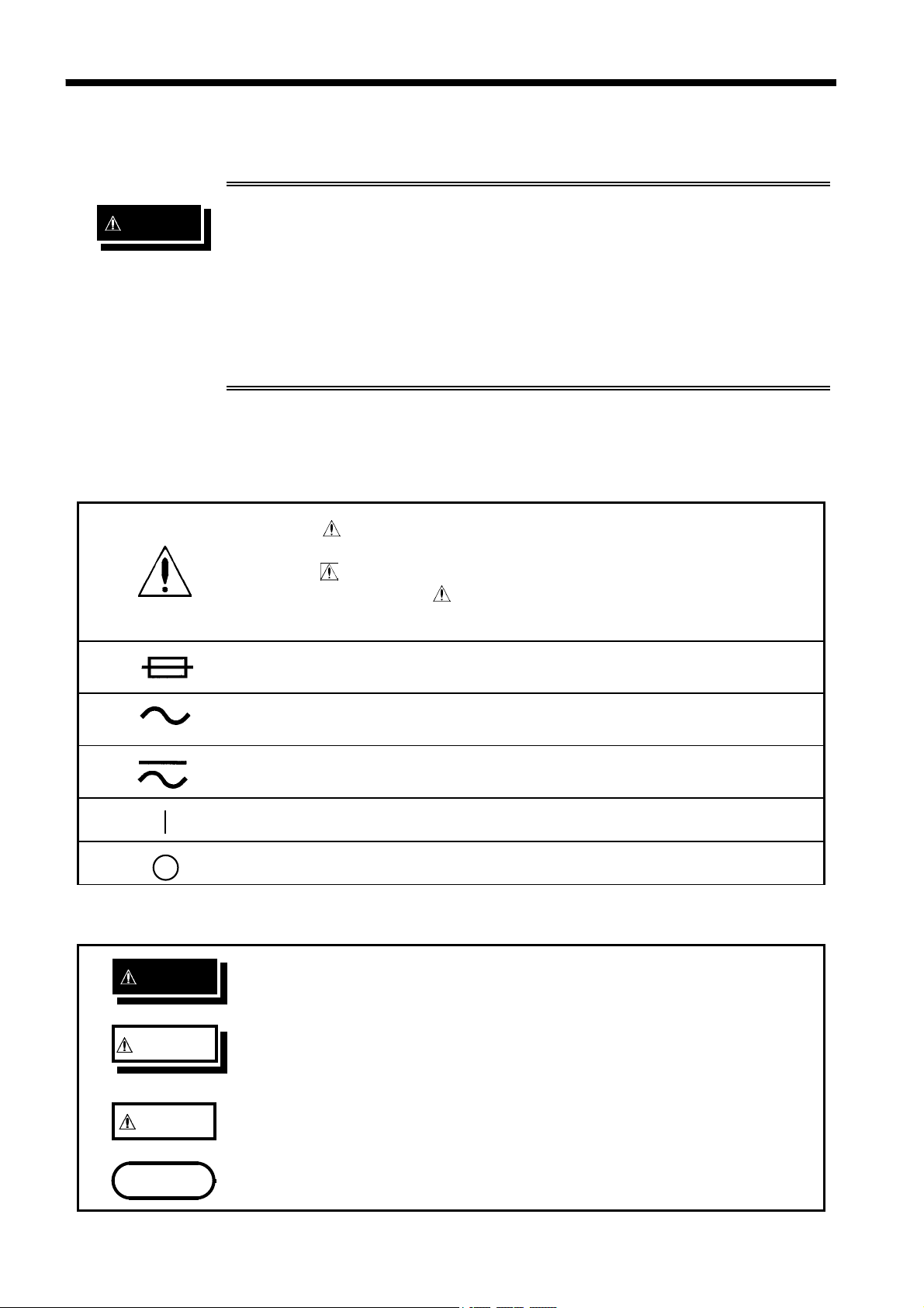
Safety symbols
・
The
should refer to a corresponding topic in the manual (marked with
the
・
In the manual, the
information that the user should read before using the product.
symbol printed on the product indicates that the user
symbol) before using the relevant function.
symbol indicates particularly important
DANGER
WARNING
CAUTION
Indicates a fuse.
Indicates AC (Alternating Current).
Indicates both DC (Direct Current) and AC (Alternating Current).
Indicates the ON side of the power switch.
Indicates the OFF side of the power switch.
The following symbols in this manual indicate the relative importance of cautions
and warnings.
Indicates that incorrect operation presents an extreme hazard that
could result in serious injury or death to the user.
Indicates that incorrect operation presents a significant hazard that
could result in serious injury or death to the user.
Indicates that incorrect operation presents a possibility of injury to
the user or damage to the product.
NOTE
────────────────────────────────────────────────────
Safety Notes
product.
Advisory items related to performance or correct operation of the
Page 6
iii
────────────────────────────────────────────────────
We define measurement tolerances in terms of rdg. (reading) and dgt. (digit) values,
with the following meanings:
rdg. (displayed or indicated value)
The value currently being measured and indicated on the measuring product.
dgt. (resolution)
The smallest displayable unit on a digital measuring product, i.e., the input value
that causes the digital display to show a "1".
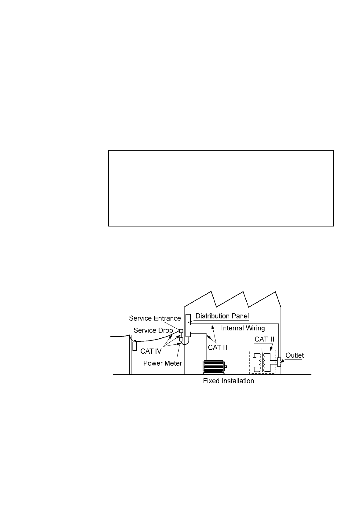
Measurement categories
To ensure safe operation of measurement product, IEC 61010 establishes safety
standards for various electrical environments, categorized as CAT II to CAT IV, and
called measurement categories.
CAT II Primary electrical circuits in equipment connected to an AC electrical
outlet by a power cord (portable tools, household appliances, etc.)
CAT II covers directly measuring electrical outlet receptacles.
CAT III Primary electrical circuits of heavy equipment (fixed installations)
connected directly to the distribution panel, and feeders from the
distribution panel to outlets.
CAT IV The circuit from the service drop to the service entrance, and to the power
meter and primary overcurrent protection device (distribution panel).
Using a measurement product in an environment designated with a higher-numbered
category than that for which the product is rated could result in a severe accident,
and must be carefully avoided.
Use of a measurement instrument that is not CAT-rated in CAT II to CAT IV
measurement applications could result in a severe accident, and must be carefully
avoided.
────────────────────────────────────────────────────
Safety Notes
Page 7

iv
────────────────────────────────────────────────────
Notes on Use
Follow these precautions to ensure safe operation and to obtain the full benefits of
the various functions.
WARNING
Before turning the product on, make sure the source voltage
matches that indicated on the product's power connector.
Connection to an improper supply voltage may damage the product
and present an electrical hazard.
To avoid electrical accidents and to maintain the safety specifications
of this instrument, connect the power cord provided only to a 3contact (two-conductor + ground) outlet.
To avoid electric shock, do not remove the cover panel. The internal
components of the product carry high voltages and may become very
hot during operation.
To avoid electric shock, do not allow the product to get wet, and do
not use it when your hands are wet.
Replace the fuse only with one of the specified characteristics and
voltage and current ratings. Using a non-specified fuse or shorting
the fuse holder may cause a life-threatening hazard.
(Fuse type: 250 V T3.15 AL)
To avoid electric shock when measuring live lines, wear appropriate
protective gear, such as insulated rubber gloves, boots and a safety
helmet.
────────────────────────────────────────────────────
Notes on Use
Page 8

v
────────────────────────────────────────────────────
・
CAUTION
Before using the product, make sure that the insulation on the
probes(9296 or 9297) is undamaged and that no bare conductors are
improperly exposed. Using the product in such conditions could cause an
electric shock, so contact your dealer or Hioki representative for repair.
・
For safety reasons, only use the optional 9296 or 9297 probe for
measurement.
・
This product should be installed and operated indoors only, between 0
and 40
・
Do not store or use the product where it could be exposed to direct
and 90%RH max.
sunlight, high temperature or humidity, or condensation. Under such
conditions, the product may be damaged and insulation may deteriorate
so that it no longer meets specifications.
・
To avoid electrocution, turn off the power to all devices before plugging or
unplugging any of the interface connectors.
・
To avoid damaging the output cable, grasp the connector, not the cable,
when unplugging the cable from the product.
・
To avoid damaging probes (especially where the leads connect to the
probes), do not kink or pull on the leads.
・
Keep in mind that, in some cases, conductors to be measured may be
hot.
・
Avoid obstructing the ventilation holes on the sides of the 3157, as it could
overheat and be damaged, or cause a fire.
・
To avoid damage to the product, protect it from vibration or shock during
transport and handling, and be especially careful to avoid dropping.
・
Do not insert a board other than optional interface boards into the
Interface slot. The unit software or calibration data may be lost.
・
In the event that the equipment malfunctions in any manner during use,
turn off the power immediately, and contact your dealer or HIOKI
representative.
・
NOTE
Do not use the product near a device that generates a strong electromagnetic field
or electrostatic charge, as these may cause erroneous measurements.
・
This product may cause interference if used in residential areas. Such use
must be avoided unless the user takes special measures to reduce
electromagnetic emissions to prevent interference to the reception of radio
and television broadcasts.
────────────────────────────────────────────────────
Notes on Use
Page 9

vi
────────────────────────────────────────────────────
Contents and Indications of this Manual
Chapter 1: Overview
Describes an overview, features, and the names and functions of the
parts of the unit.
Chapter 2: Testing Arrangements
Describes particulars of testing arrangements.
Chapter 3: Testing Method
Describes procedures for setting, testing, and test results judgement.
Chapter 4: Optional Functions
Describes procedures for setting optional functions.
Chapter 5: Saving/loading Preset Values
Describes procedure for saving and loading test values.
Chapter 6: External I/O
Describes use of the external I/O.
Chapter 7: Maintenance, Inspection and Ultimate Disposal
Covers the maintenance and inspection, fuse replacement, and ultimate
disposal.
Chapter 8: Specifications
Contains the unit specifications such as the general specifications,
measurement accuracy, etc. of the unit.
Appendix:
Covers the options of the unit and standards.
Indications in the Instruction Manual
Indicates that settings can be made for optional functions.For more information, see
Chapter 4, "Optional Functions."
In this Instruction Manual, the flashing area of the screen is represented in reverse
mode.
In this figure, for example, the current value of 25.0 A flashes.
────────────────────────────────────────────────────
Contents and Indications of this Manual
Page 10

1
────────────────────────────────────────────────────
Chapter 1
Overview
1.1 Product Introduction
The HIOKI "3157 AC GROUNDING HiTESTER" is designed for protection circuit
testing of a wide range of electrical equipment, including industrial machinery,
medical equipment, and measuring instruments.
Using a constant current system, the HIOKI 3157 provides stable output current.
The unit is capable of accurate four-terminal measurement. The comparator
function, timer function, and screening function permit simple testing, conforming
to technical standards and regulations.
────────────────────────────────────────────────────
1.1 Product Introduction
Page 11

2
────────────────────────────────────────────────────
1.2 Features of the 3157
(1) Simple testing procedures conforming to technical standards
This unit incorporates a constant current method to provide stable output current.
Voltage drop is measured with four terminals. The 3157 is also equipped with a
function timer and a screening function, using maximum and minimum values,
allowing straightforward testing in conformance with applicable technical standards.
(2) Test data counting function
This function enables test point counting for measured objects that have large
numbers of test points.
(3) Soft-start function
By constantly monitoring current fluctuations, this function checks that the probe is
connected to the measured object. The function also prevents sparking when the
probe is connected to a test point after measurement begins.
(4) Compact and lightweight
With a compact lightweight design, the unit is highly portable and well-suited to
maintenance measurement.
(5) Fluorescent indicator
The large, easy-to-read fluorescent display permits quick checking of the testing
state and result.
(6) Probe
The 3157 is equipped with an alligator-clip probe (the 9296 CURRENT
PROBE) and a switching probe (the 9297 CURRENT APPLY PROBE).
To improve testing efficiency, the push switch on the switching probe
starts testing and inactivates result-checking mode.
(7) Saving testing set values
This unit is provided with a function for saving the set values used in a test,
allowing quick switching between different testing set values to meet a variety of
standards and regulations. Up to 20 values may be saved.
(8) Interface
By using the optional 9593-02 RS-232C and 9518-02 GP-IB INTERFACE boards,
the user can perform automatic testing and save the test results by means of a PC.
Test results can be printed on the optional 9442 PRINTER. Connecting with the
optional 3155 LEAK CURRENT HiTESTER enables testing and the test results can
be saved and printed together with the 3155 leakage current test results.
(9) External I/O
The external I/O terminal generates signals according to the state of the 3157.
It can be used to feed signals for the start and stop key.
────────────────────────────────────────────────────
1.2 Features of the 3157
Page 12
3
────────────────────────────────────────────────────
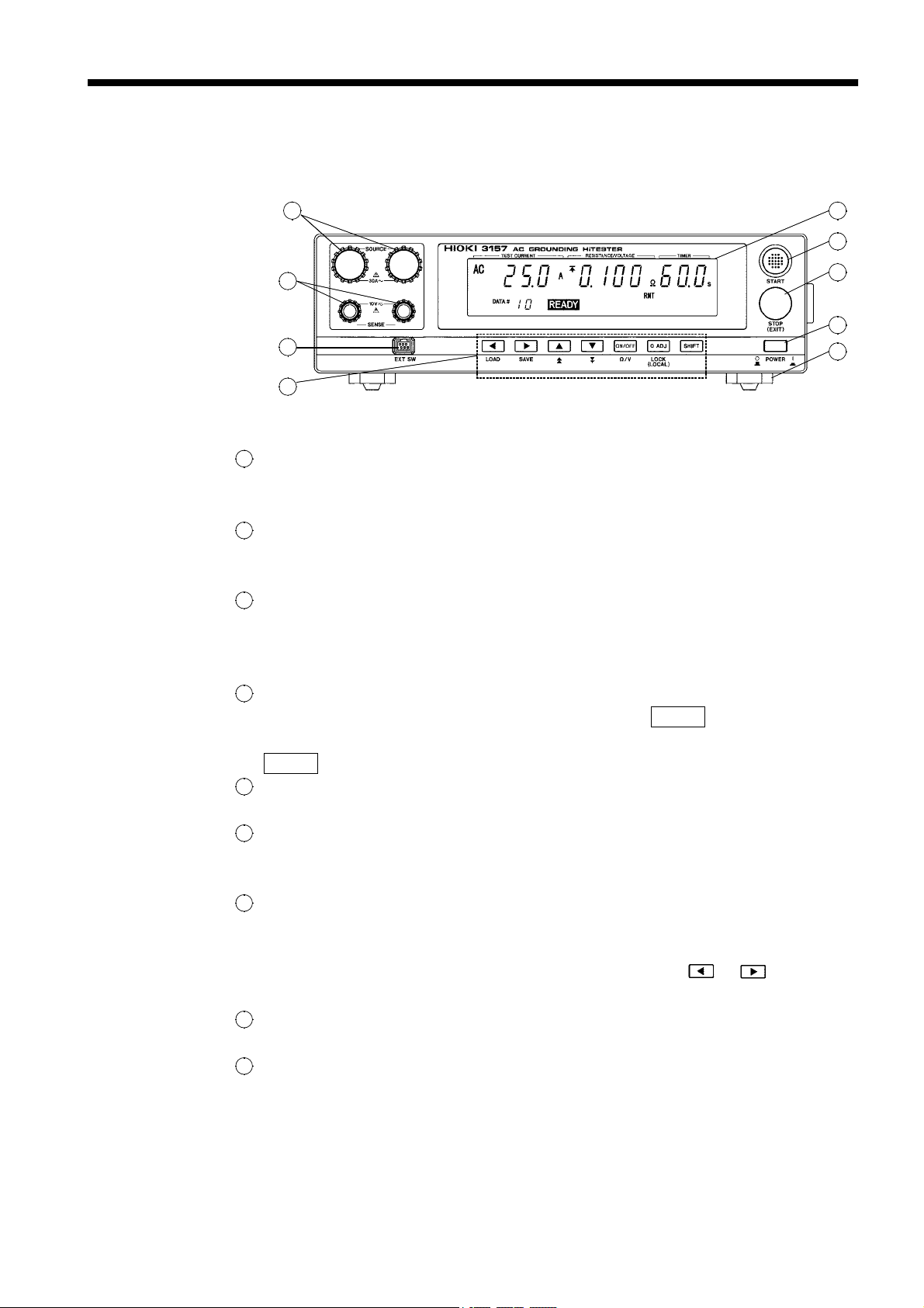
1.3 Names and Functions of Parts
Front panel
1
5
6
2
3
4
1
Current output terminal
Providing current during a test, this terminal serves as the SOURCE terminal for
four-terminal measurement.
2
Voltage measurement terminal
Used to measure voltage. This terminal serves as the SENSE terminal for
four-terminal measurement.
3
External switch terminal
Used for the switch signal line connected to the switching probe (the 9297
CURRENT APPLY PROBE), the 9613 REMOTE CONTROL BOX(SINGLE) or
the 9614 REMOTE CONTROL BOX(DUAL).
4
Rubber keys
The seven rubber keys include six function keys and a
SHIFT
key.
The six function keys offer a variety of settings, used in combination with the
SHIFT
5
Fluorescent indicator
key.
Displays various kinds of information, such as test state and results.
6
START key
Used to start a test. On starting a test with a preset value, the unit enters TEST
mode. The test starts whether or not the flashing cursor is displayed.
7
STOP key
・
Used to perform forcible ending of a test.
・
Pressing the STOP key when the flashing cursor is displayed causes it to
disappear. To display the flashing cursor again, press the
or key. The
cursor appears, displaying the preset current value.
8
Main power switch
Powers the 3157 on or off.
9
Stand
The 3157 can be tilted up by using this stand.
7
8
9
────────────────────────────────────────────────────
1.3 Names and Functions of Parts
Page 13
4
────────────────────────────────────────────────────
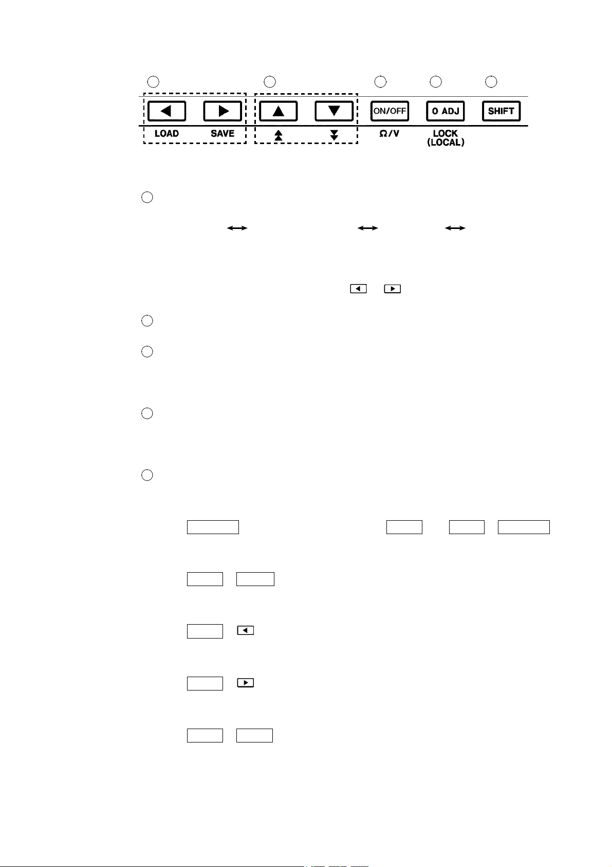
Rubber keys (in READY state)
1 2 3 4 5
1
Left/Right cursor key
Moves the flashing cursor. The switching range is preset before shipment: Preset
current value
Frequency.
The key can be set to shift to the minimum test value and the test data count, when
these values are set with the optional functions.
To display the flashing cursor, press the
displaying the preset current value.
2
Up/Down cursor key
Changes the position at which the flashing cursor appears.
3
ON/OFF (Ω/V) key
Switches on/off the set value for the position of the flashing cursor.
However, this key can't perform the switching on/off of the preset current value. If
turned off, the set value is not used in testing.
4
Zero Adjustment key
Use this key to perform zero adjustment within the effective range of adjustment.
The zero adjustment function is active when the 0ADJ lamp is lit.
For zero adjustment procedure, see Section 3.4, "Zero Adjustment Function."
5
SHIFT key
Used in combination with other keys.
Maximum Test Value Testing time Output
or key. The cursor appears,
(1) Switching between voltage and resistance indicators
Press
ON/OFF
(Ω/V) while holding down the
SHIFT
key (
(Ω/V)) to switch between voltage and resistance indicators.
(2) Setting the key lock
Press
SHIFT
+
0ADJ
(LOCK) key to activate key-lock mode.
For more information, see Section 3.5, "Key-lock Function."
(3) Displaying the Preset-data loading screen
Press
SHIFT
+ to display the Preset-data loading screen.
For more information, see Chapter 5, "Saving/loading Preset Values."
(4) Displaying the Preset-data saving screen
Press
SHIFT
+ to display the Preset-data saving screen.
For more information, see Chapter 5, "Saving/loading Preset Values."
(5) Displaying the Optional function setting screen
Press
SHIFT
+
STOP
to display the Optional function setting screen.
For more information, see Chapter 4, "Optional Functions."
SHIFT
+
ON/OFF
────────────────────────────────────────────────────
1.3 Names and Functions of Parts
Page 14
5
────────────────────────────────────────────────────
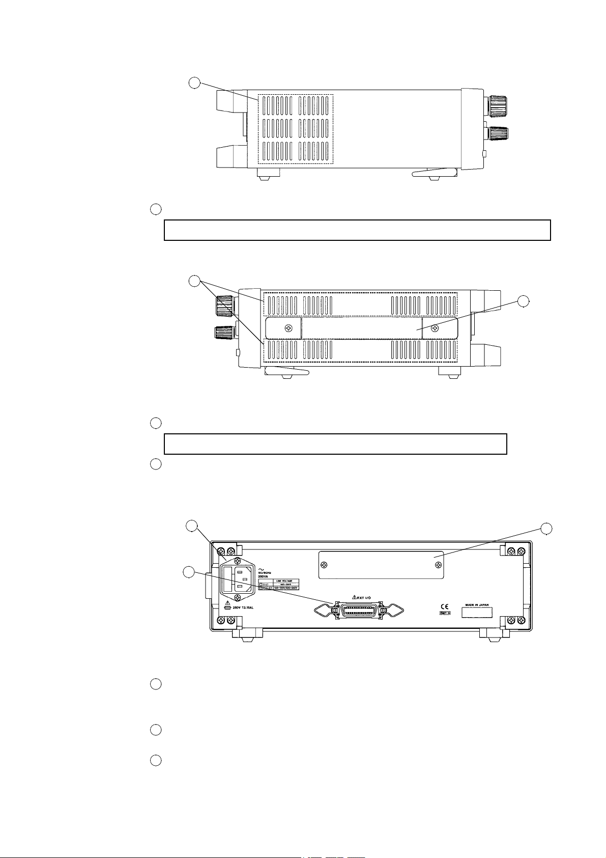
Left side view
1
1
Air outlet
Never touch the air outlet. The air outlet is provided with an internal cooling fan.
Right side view
1
2
Rear panel
1
Air inlet
Never touch the air inlet. Air for cooling is drawn through this opening.
2
Handle
This is used for transporting the 3157.
1
2
1
Power inlet
Connect the grounded three-core power cord supplied here. Integrated with a fuse
holder.
2
External I/O terminal
For output of 3157 state and input of start and stop signals.
3
Interface slot
Expansion slot for installation of the optional 9593-02 RS-232C INTERFACER or
9518-02 GP-IB INTERFASE board.
3
────────────────────────────────────────────────────
1.3 Names and Functions of Parts
Page 15
6
────────────────────────────────────────────────────
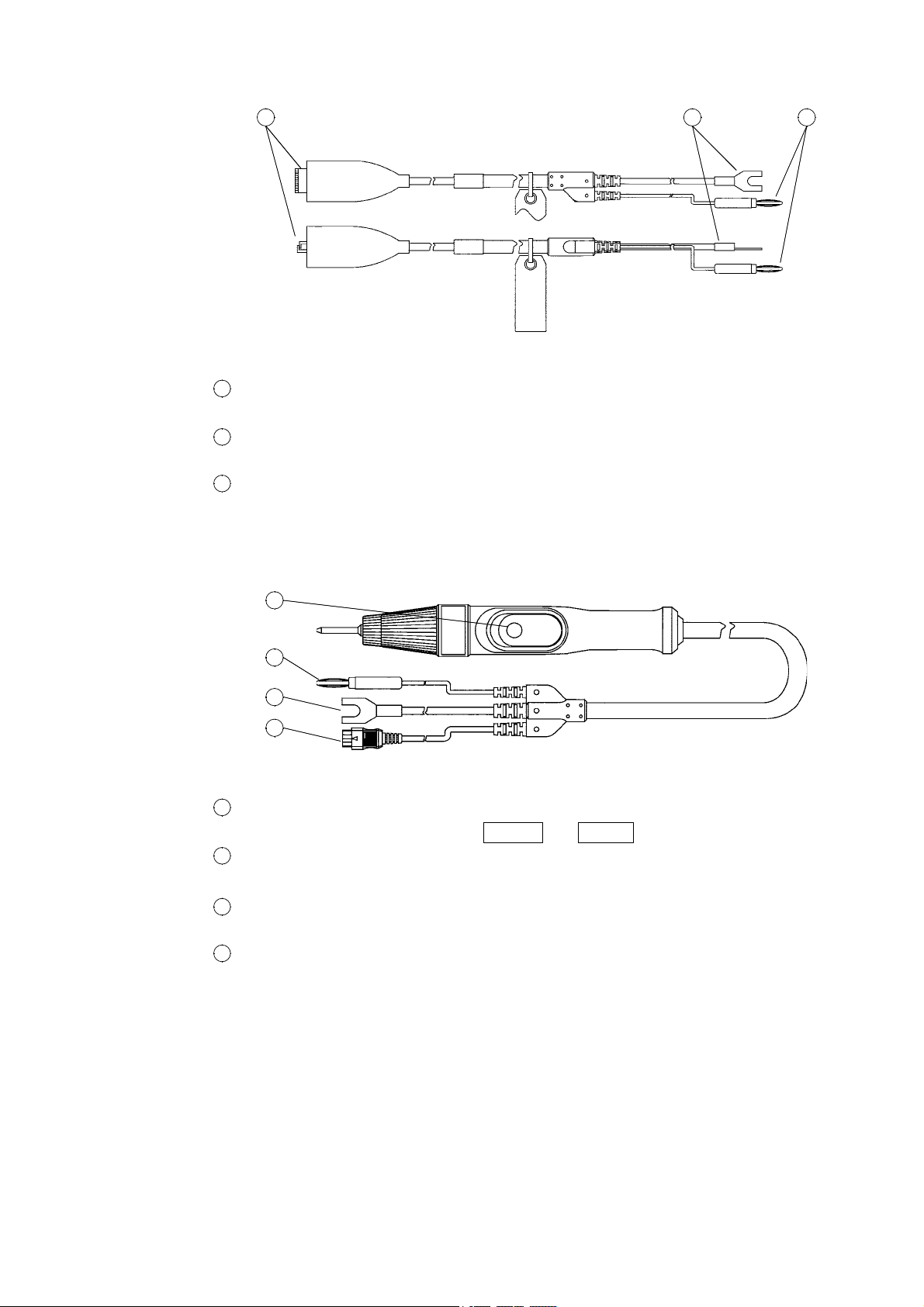
9296 CURRENT PROBE
1 2 3
1
Alligator clip
Clipped to the measured object.
2
Current output plug
Connected to the unit's current output terminal.
3
Banana-type voltage measurement plug
Connected to the unit's voltage measurement terminal.
9297 CURRENT APPLY PROBE
1
2
3
4
1
Push switch
External switch equivalent for the
2
Banana-type voltage measurement plug
Connected to the unit's voltage measurement terminal.
Current output plug
3
Connected to the unit's current output terminal.
Switch signal line plug
4
Connected to the unit's controller terminal.
START
and
STOP
keys.
────────────────────────────────────────────────────
1.3 Names and Functions of Parts
Page 16
7
────────────────────────────────────────────────────
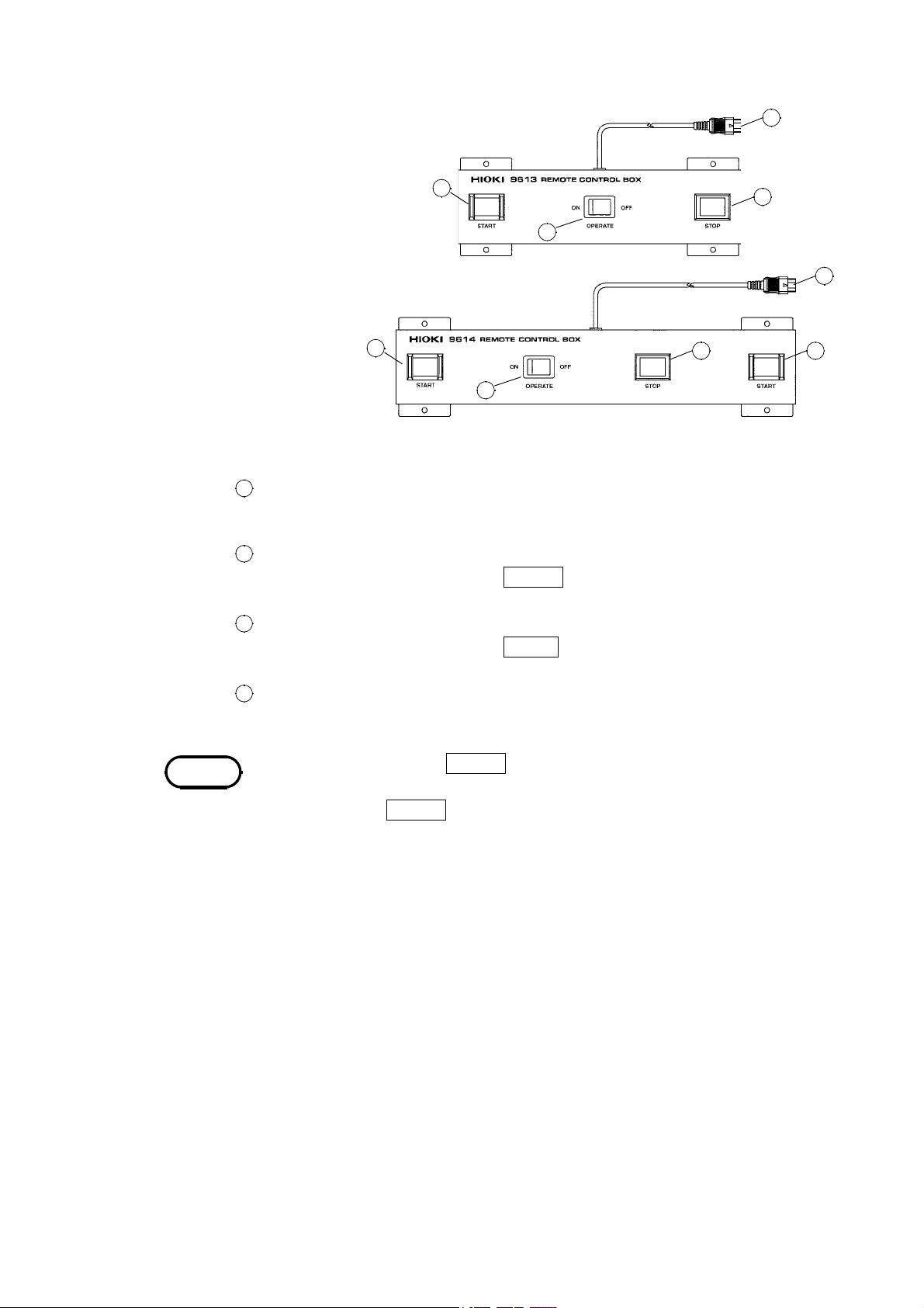
REMOTE CONTROL BOX
9613 REMOTE CONTROL BOX (SINGLE)
2
1
4
3
9614 REMOTE CONTROL BOX (DUAL)
OPERATE switch
1
2
1
3 2
Used to enable remote-control operation. When this switch is ON, the START and
STOP keys for remote control are active.
2
START key
Works in the same manner as the
START
key on the unit. With the 9614 dual
remote-control box, the two START switches must be pressed.
3
STOP key
Works in the same manner as the
STOP
key on the unit. The STOP key is ON
during a test or when a voltage is being output.
4
Switch signal line plug
Connect to the external switch terminal on the unit.
4
NOTE
Priority for control of the
START
key is in the following order: the external switch,
the external I/O, and the front panel of the unit. Connecting the switch signal line
plug disables the
START
key on the front panel of the unit and the start signal for
the external I/O.
────────────────────────────────────────────────────
1.3 Names and Functions of Parts
Page 17
9
────────────────────────────────────────────────────
Chapter 2
Testing Arrangements
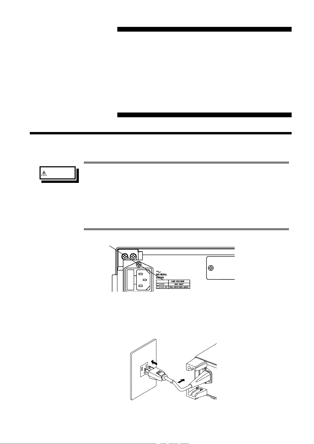
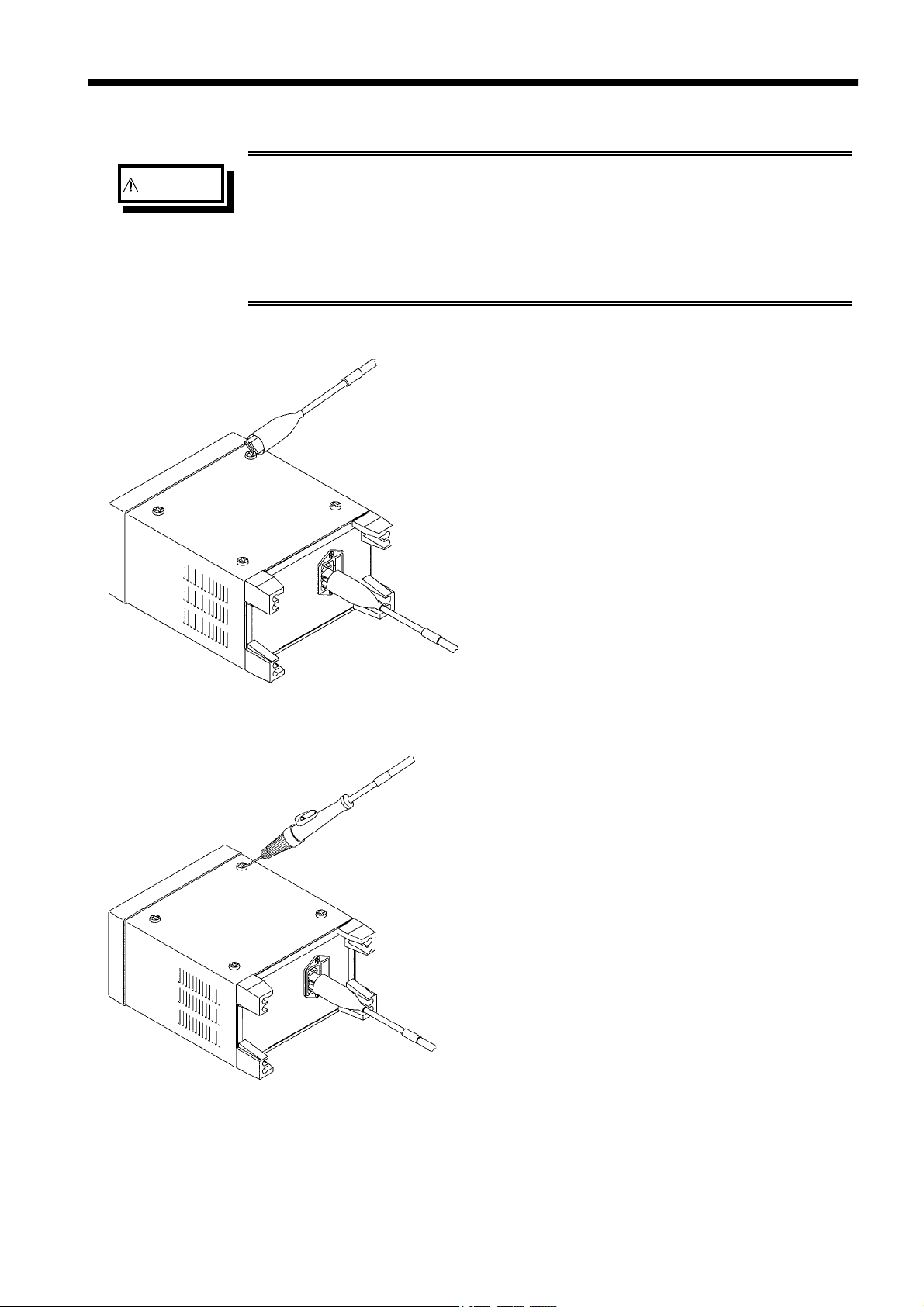
2.1 Power Cord Connection
WARNING
The 3157 and the 3157-01 use different rated power voltages. Before
turning the product on, make sure the source voltage matches that
indicated on the product's power connector. Connection to an
improper supply voltage may damage the product and present an
electrical hazard.
To avoid electric shock and ensure safe operation, connect the
power cable to a grounded (3-contact) outlet.
Supply voltage indicated on the rear panel
(1) Be sure that the main power switch is turned to OFF.
(2) Connect the grounded three-core power cord provided to the power inlet on the back
of the unit.
(3) Insert the plug into the grounded outlet.
────────────────────────────────────────────────────
2.1 Power Cord Connection
Page 18
10
────────────────────────────────────────────────────
2.2 Powering on and off the Unit
WARNING
NOTE
Before turning the product on, make sure the source voltage matches
that indicated on the product's power connector. Connection to an
improper supply voltage may damage the product and present an
electrical hazard.
・
Allow 10 minutes warming up after powering on.
・
To use the external controller, the external I/O terminal, and the interface, you
must connect them before startup. Only devices or peripherals connected before
startup are activated. Connection following startup may lead to operational or
equipment failure.
For connection procedures, see Section 2.3, "Probe Connection" for the external
controller, Chapter 6, "External I/O" for the external I/O terminal, and the
instruction manual accompanying the interface for each interface.
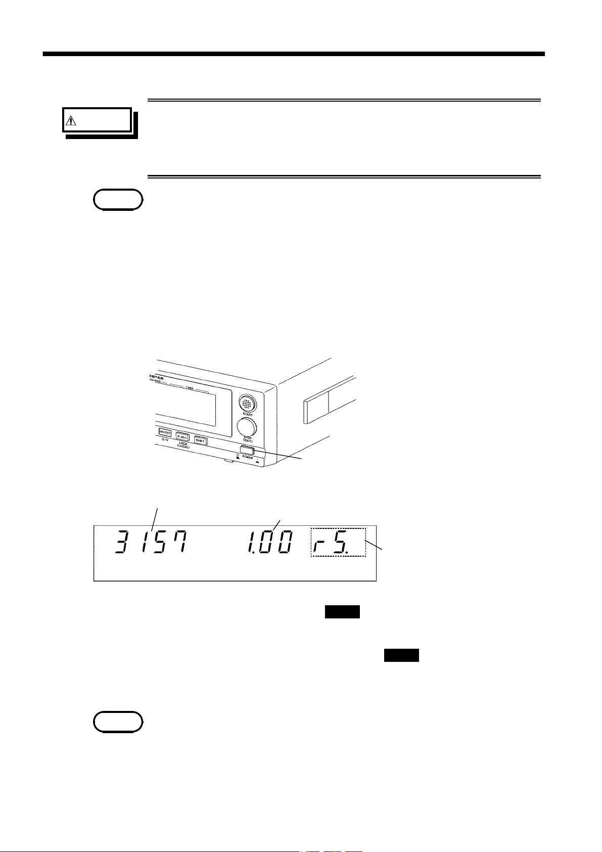
Powering on the unit
(1) Turn the main power switch to ON(l).
(2) The model name and version number are displayed as below:
The model name is displayed.
(3) The unit enters READY state five seconds after startup.
Key operation is disabled unless the
Powering off the unit
After the testing has finished, being sure that the
the main power switch on the back of the unit to OFF.
Note that the unit may be damaged if the main power switch is turned to OFF while
the unit is outputting current.
NOTE
The current settings are all preserved when the unit is next turned on. If there has
been a power failure or other malfunction of the power supply, the settings in effect
at the time the malfunction occurred are preserved.
Main power switch
The version number is displayed.
"Version 1.00" is displayed.
READY
lamp is lit.
Indicates active interfaces.
G.01: 9518-02 GP-IB INTERFACE
rS: 9593-02 RS-232C INTERFACE
rS.P: 9442 PRINTER
READY
lamp is turned on, turn
────────────────────────────────────────────────────
2.2 Powering on and off the Unit
Page 19
11
────────────────────────────────────────────────────
2.3 Probe Connection
WARNING
To avoid shock and short circuits, turn off all power before
connecting probes.
To avoid electrical accidents, confirm that all connections are secure.
The increased resistance of loose connections can lead to
overheating and fire.
The 9296 CURRENT PROBE (with alligator clip) and 9297 CURRENT APPLY
PROBE are available as optional probes. Connect two sets of the 9296 or a single
combined set of 9296 and 9297.
You can use a custom-built probe. If you do use a custom-built probe, make sure
the wire/cable used for it has sufficient current capacity (AWG 12/cross-sectional
2
area 3.5 mm
min.)
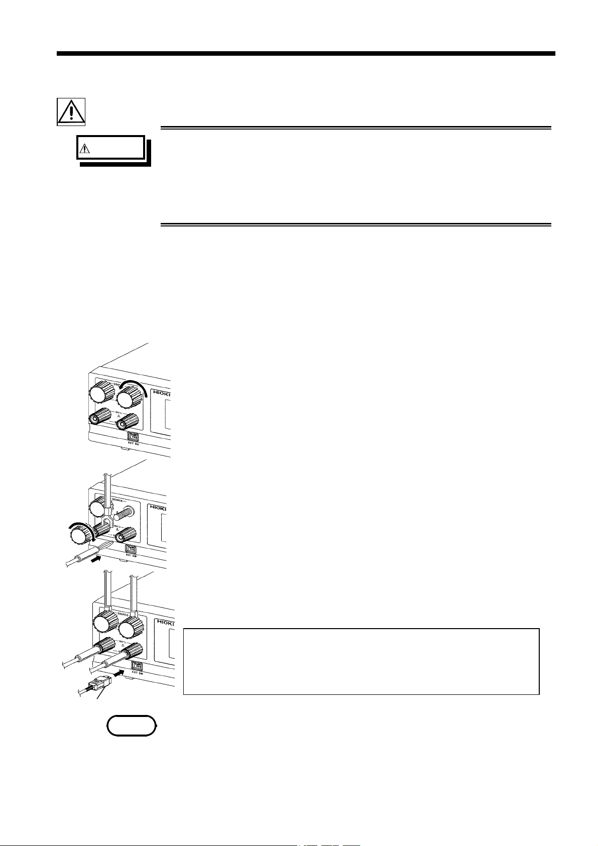
(1) Rotate the current output terminal counter-clockwise to open.
(2) Connect the current output plug as shown in the figure on the left.
(3) Rotate the current output terminal clockwise to close.
(4) Insert the banana-type voltage measurement plug into the voltage
measurement terminal.
(5) With the 9296 CURRENT PROBE, be sure to connect the probe to the other
terminals using the same procedure.
To use the 9297 CURRENT APPLY PROBE, insert the switch signal line
plug into the external switch terminal.
To use the push switch on the 9297 CURRENT APPLY PROBE, use the
・
current output terminal and the voltage measurement terminal on the right,
as shown in the figure.
Make sure the switch signal line plug is correctly oriented. If the plug is
・
dislocated during testing, the unit will enter READY state.
Switch signal line plug
・
NOTE
To activate the push switch, connect the switch signal line plug to the external
switch terminal before startup. For more information on the push switch, see
Section 4.9, "Momentary OUT."
・
The 9297 CURRENT APPLY PROBE can be used unless it is connected to the
external switch terminal. In this case, the push switch cannot be used.
────────────────────────────────────────────────────
2.3 Probe Connection
Page 20
12
────────────────────────────────────────────────────
2.4 Short Bar Connection
WARNING
To avoid shock and short circuits, turn off all power before
connecting probes.
To avoid electrical accidents, confirm that all connections are secure.
The increased resistance of loose connections can lead to
overheating and fire.
In a test using two terminals, be sure to use the current output
terminal. Use of the voltage measurement terminal may lead to the
terminal overheating, resulting in burns or equipment damage.
When connecting a probe incompatible with four-terminal measurement, or when
measuring with two terminals, connect the short bar between the voltage measurement
terminal (the SENSE terminal) and the current output terminal (the SOURCE
terminal). Connect to both the voltage measurement terminal and the current output
terminal. In this case, be sure to connect the probe to the current output terminal.
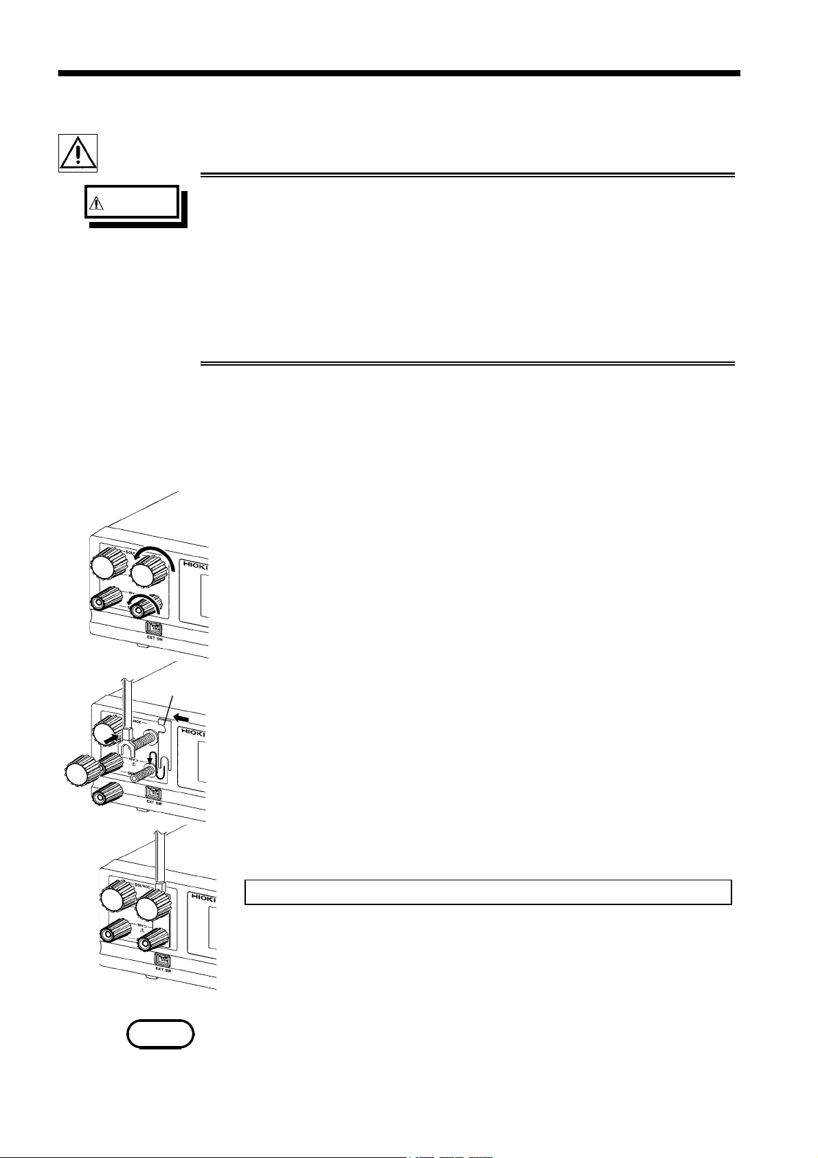
Short bar
(1) Rotate the current output terminal and the voltage measurement terminal
counter-clockwise to open.
(2) Connect the probe and short bar as shown in the figure on the left.
(3) Rotate the current output terminal and the voltage measurement terminal
clockwise to close. Be sure to connect the other terminals using the same
procedure.
In a test using two terminals, be sure to use the current output terminal.
*The figure on the left shows how to connect the probe and the shortbar to the
terminals on the right. The shortbar can be connected to the terminals on the
left in the same manner.
NOTE
Measurement with two terminals will be affected by a voltage drop in the probe,
leading to inaccurate results. Before beginning a test, perform zero adjustment (see
Section 3.4, Zero Adjustment Function).
────────────────────────────────────────────────────
2.4 Short Bar Connection
Page 21
13
────────────────────────────────────────────────────
2.5 Connecting the REMOTE CONTROL BOX
WARNING
NOTE
To avoid shock and short circuits, turn off all power before connecting
probes.
To prevent malfunctions, do not remove the remote-control box following startup.
Before removing it, be sure to turn OFF the power.
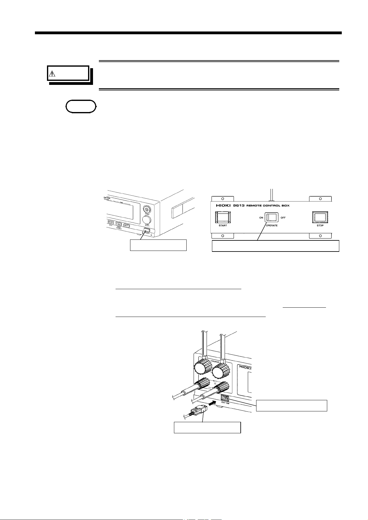
Connection of the remote-control box (9613/9614) enables start/stop operations to
be performed easily.
(1) Make sure the Main Power switch and OPERATE switch on the remote-control
box are OFF.
Main power switch
OPERATE switch on the remote-control box
(2) Insert the switch signal line plug into the external switch terminal.
Check the direction of the switch signal line.
(3) Turn ON the OPERATE switch of the remote-control box. The OPERATE
switch can be turned ON/OFF even following startup.
External switch terminal
Switch signal line plug
────────────────────────────────────────────────────
2.5 Connecting the REMOTE CONTROL BOX
Page 22
14
────────────────────────────────────────────────────
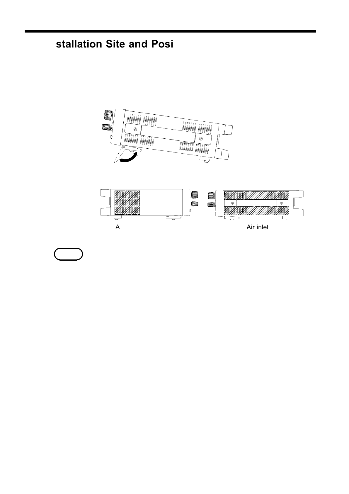
2.6 Installation Site and Position
Place on a stable, flat surface, using the four-footed stand. Orienting the unit
vertically will block its air outlet, greatly increasing the risk of overheating. In
positioning the unit, make sure the air inlet and outlet are kept open.
Stand
Left side view Right side view
NOTE
Air inletAir outlet
・
Do not insert the foreign objects into the air inlet or outlet.
・
Do not apply strong downward pressure with the stand extended. Damage to the
stand will result.
・
Magnetic fields generated by the unit may affect CRT displays. During testing,
keep the current probe away from such subjects.
────────────────────────────────────────────────────
2.6 Installation Site and Position
Page 23
15
────────────────────────────────────────────────────
2.7 Connection to the Measured Object
WARNING
To avoid burns, never touch the output current terminal, probe tip, or
contact point while testing (i.e., in TEST state).
Take particular care to avoid touching the tip of the current
application probe, which may be quite hot when operating, due to its
small surface area.
(1) Connecting using two 9296 units
Connect one 9296 to the protection ground terminal
on the measured object.
Connect the other 9296 to the test point. Connect
the probe firmly to prevent disconnection during
testing.
During current output, take care to ensure that
adjacent probes do not touch, as this may result in a
short-circuit.
(2) Connecting using a single combined set of
9296 and 9297
Connect the 9296 to the protection ground terminal
on the measured object.
Connect the 9297 to the test point. Connect the
probe firmly to prevent disconnection during testing.
During current output, take care to ensure that
adjacent probes do not touch, as this may result in a
short-circuit.
────────────────────────────────────────────────────
2.7 Connection to the Measured Object
Page 24
16
)
)
)
)
)
)
AB(
)
)
)
)
)
)
)
)
AB(
)
)
)
────────────────────────────────────────────────────
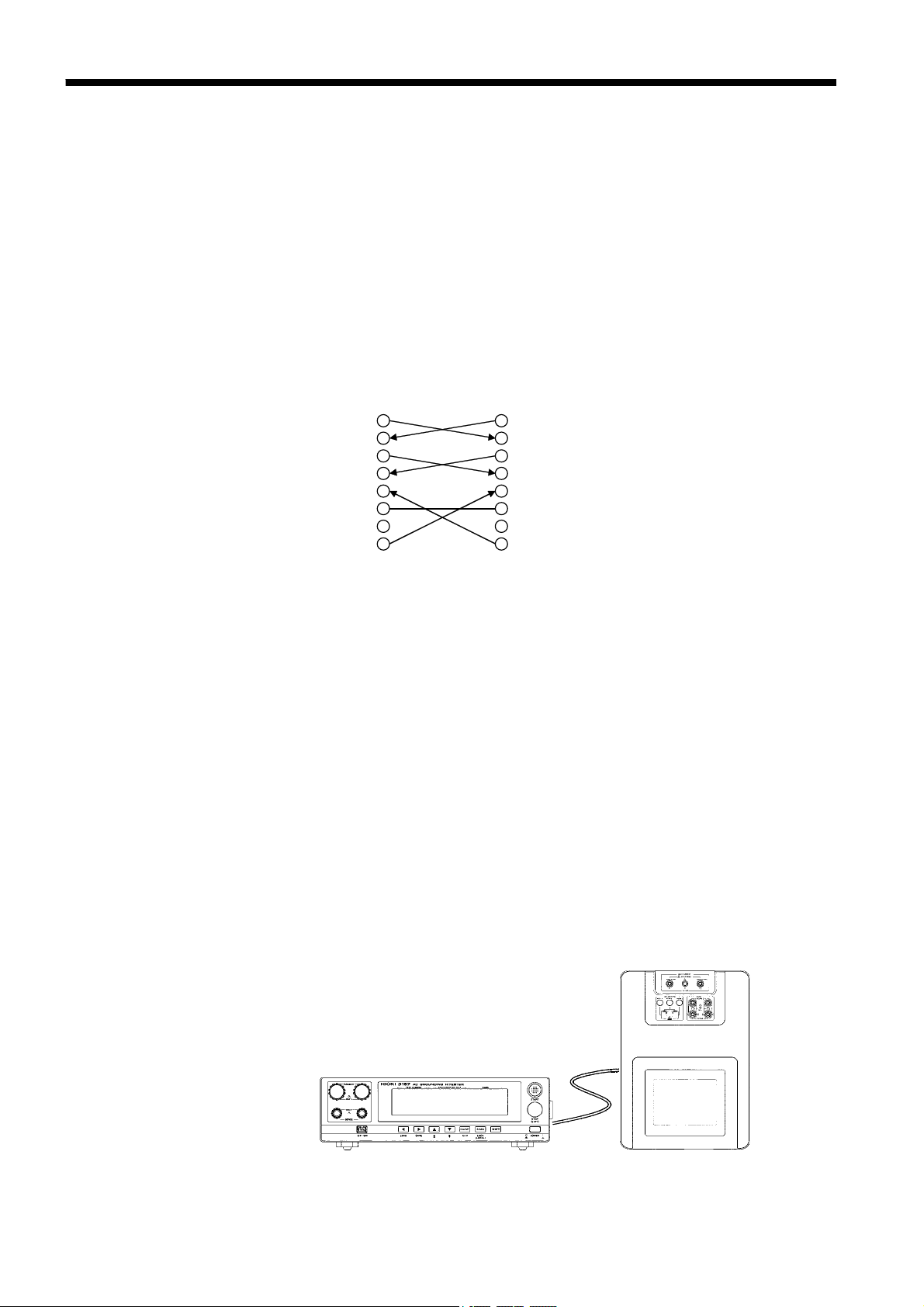
2.8 Connection to the 3155 LEAK CURRENT HiTESTER
Attaching optional 9593-02 RS-232C INTERFACE to 3157 enables testing when
connected with 3155.
3155 sends command to 3157 to start testing and receives test results when the
3157 testing is complete. The test results can be saved and printed together with
the 3155 leakage current test results.
For usage for the 3155, see 3155 (-01) Instruction Manual.
When connecting 3155 with 3157 (9593-02), use connection cable as specified
below.
3157(9593-02
GND
2
3
4
5
6
7
8
20
BA(TxD
BB(RxD
CA(RTS
CB(CTS
CC(DSR
CF(DCD
CD(DTR
3155
3
BA(TxD
2
BB(RxD
7 CA(RTS
CB(CTS
8
CC(DSR
6
GND
5
CF(DCD
1
CD(DTR
4
Specification: D-subminiature 25-pin male to D-subminiature 9-pin female
connectors, with "crossed" data connections
Settings
(1) Leave power OFF for both 3155 and 3157 while connecting each RS-232C
connector with the RS-232C cable.
(2) Turn the power ON for both 3155 and 3157.
(3) Set up 3157 test settings. Measurement does not start unless the following
conditions are met.
1. Test settings
・
Unit of the maximum and minimum test values: Resistance
・
Test time: ON
・
Maximumtestvalue:ON
When the optional minimum test value setting function is ON.
・
Minimumtestvalue:OFF
2. Optional function setting
Endless timer function: Not set
────────────────────────────────────────────────────
2.8 Connection to the 3155 LEAK CURRENT HiTESTER
Page 25
17
e
────────────────────────────────────────────────────
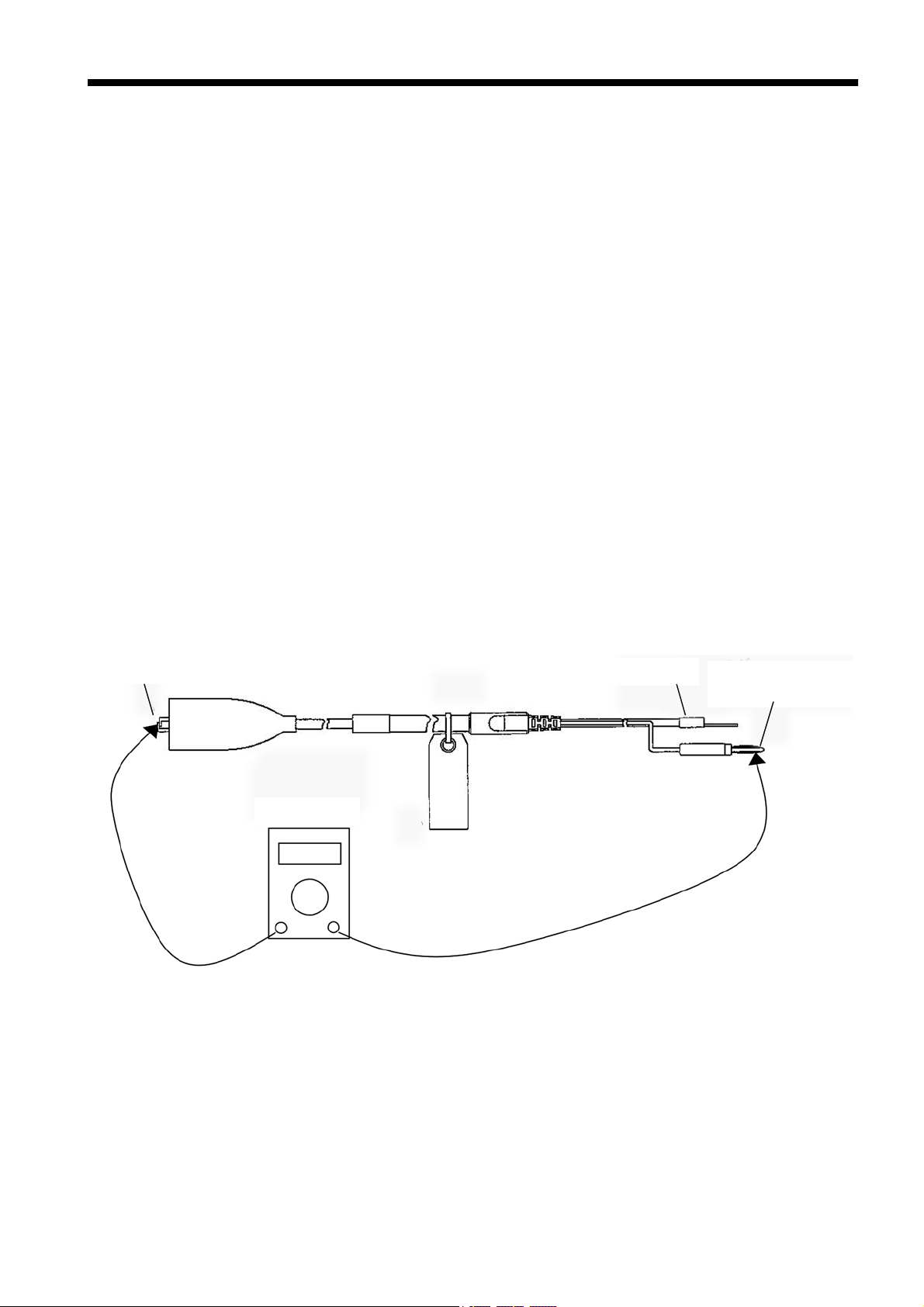
2.9 Pre-operation Inspection
By using the optional two sets of the 9296 CURRENT PROBEs or using each of
the 9296 and the 9297 CURRENT APPLY PROBE, the user can perform fourterminal measurement. In this case, the damage on the cable connecting to the
voltage measurement terminal (the SENSE terminal) will affect the measurement
values.
The 3157 cannot detect the open circuit of this voltage measurement cable when
performing four-terminal measurement. So, please follow the pre-operation
inspection below.
Prepare the follows.
・
9296 CURRENT PROBE or 9297 CURRENT APPLY PROBE
・
Resistance measuring device (e.g. tester)
For the 9296, measure the resistance between the alligator clip and the banana-type
voltage measurement plug. For the 9297, measure the resistance between the tip of
the probe and the banana-type voltage measurement plug.
Perform measurement on the two PROBEs to be used for four-terminal
measurement and make sure the resistance values to be under 1Ω and the wires are
not broken.
(The sketch below shows for the 9296 CURRENT PROBE.)
Alligator clip
Tester or etc.
Current output plug
Banana-type voltag
measurement plug
────────────────────────────────────────────────────
2.9 Pre-operation Inspection
Page 26

19
────────────────────────────────────────────────────
Chapter 3
Testing Method
This chapter describes the procedural flow for testing, making settings, and proper
testing procedure.
Read Chapter 2, "Testing Arrangements" and make the necessary arrangements for
testing.
Press
Setting the optional functions allows testing under various conditions.
For more information, see Chapter 4, "Optional Functions."
SHIFT
+
STOP
to display the Optional function setting screen.
────────────────────────────────────────────────────
Page 27
20
────────────────────────────────────────────────────
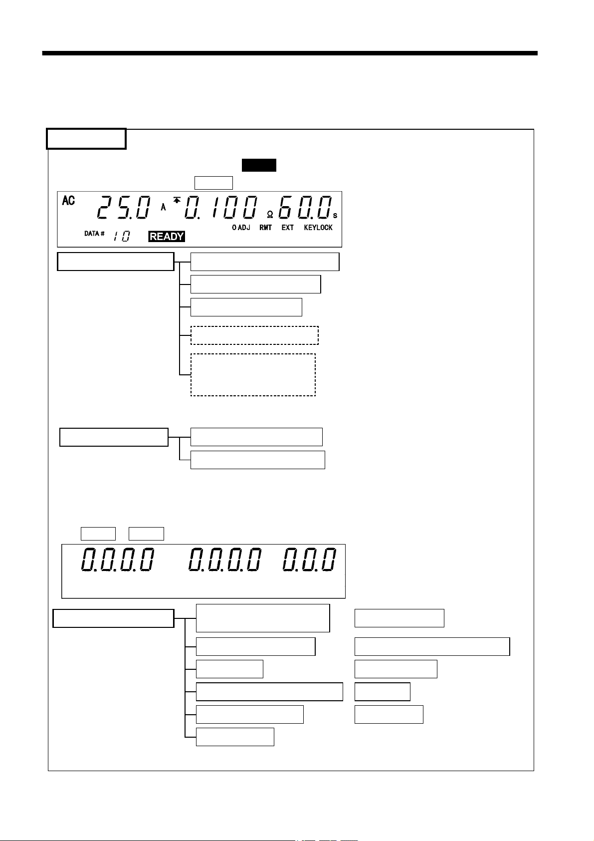
3.1 Procedural Flow for Testing and Setting Parameters
The 3157 is in one of four states:
READY state
The unit is ready for starting a test. The READY lamp is turned on.
To enter TEST state, press the
Setting in READY state
Setting other functions
START
Setting the output current value
Setting the maximum value
Setting the testing time
Setting the minimum value
Setting the output current
frequency or changing the
test count value
Performing zero adjustment
Setting the key-lock function
key while in READY state.
Settings can't be made if the endless timer is set at
"1: Set."
The minimum value can be set if the minimum
test value is set at "1: Set."
The output current frequency can be set only if
the test count value is set at"0: Not set."
Otherwise, setting and display of the test
count value are enabled.
Setting the optional functions allows testing under various conditions.
Press
────────────────────────────────────────────────────
3.1 Procedural Flow for Testing and Setting Parameters
SHIFT
Setting optional functions
+
STOP
to display the Optional Function Setting screen.
Switching the output current
frequency
PASS/FAIL hold function
Hold function
Setting the minimum test value
Endless timer function
Test data count
Setting the buzzer
Changing currents in TEST state
Momentary OUT
Test mode
Printer output
Page 28
21
────────────────────────────────────────────────────
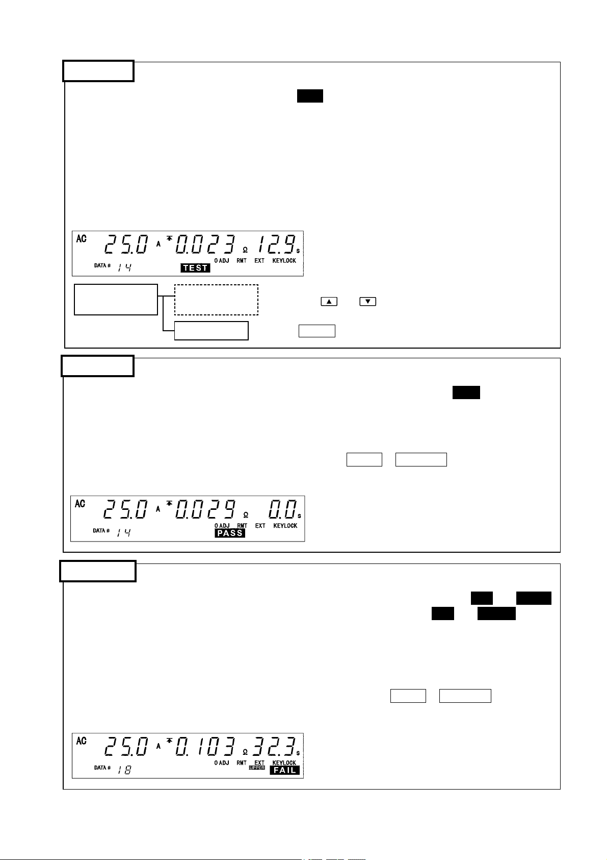
TEST state
This state indicates that a test is underway. The TEST lamp is turned on. The current preset in the
READY state is output.
The current output value, a decrease in voltage, and resistance are measured and displayed.
The measured values are compared against the comparator values preset in the READY state.
If the measured value deviate from the comparator value, the unit enters FAIL state and halts
measurement.
If the preset testing time completes without the measured value deviating from the comparator value, the
unit enters PASS state.
Key operation in
the TEST status
Changing output
current values
Forced ending
The output current value can be made changeable by
pressing the
"1: Changeable" in TEST status.
Press the STOP key.
and keys if the current is set to
PASS state
PASS indicates that the measured object passed the test set in READY state. The
on. The PASS state screen is displayed for about 1 second before switching to READY state.
Enabling the PASS hold function in the optional settings makes it possible to retain the PASS state. To
check the test results, enable the PASS/FAIL hold function.
To switch the display between resistance and voltage, press
SHIFT
+
ON/OFF
state (see Section 4.2, "PASS/FAIL Hold Function").
PASS
lamp is turned
(Ω/V) while in PASS
FAIL state
FAIL indicates that the measured object failed the test set in READY state. Both the
lamps light when the measured value exceeds the maximum test value. Both
FAIL
and
FAIL
LOWER
and
UPPER
lamps
light when the measured value drops below the minimum test value. The FAIL state screen is displayed
for about 1 second before switching to READY state.
Enabling the FAIL hold function in the optional settings makes it possible to retain the
FAIL state. To check the test results, enable the PASS/FAIL hold function.
To switch the display between resistance and voltage, press
SHIFT
+
ON/OFF
(Ω/V) while
in FAIL state (see Section 4.2, "PASS/FAIL Hold Function").
────────────────────────────────────────────────────
3.1 Procedural Flow for Testing and Setting Parameters
Page 29
22
────────────────────────────────────────────────────
3.2 Making Testing Arrangements (in READY State)
Make testing arrangements in READY state, including test parameter settings, keylocking, and zero adjustment. Saving and loading for setting data and the setting of
optional functions are made following the READY state. The READY lamp remains
lit to indicate READY state.
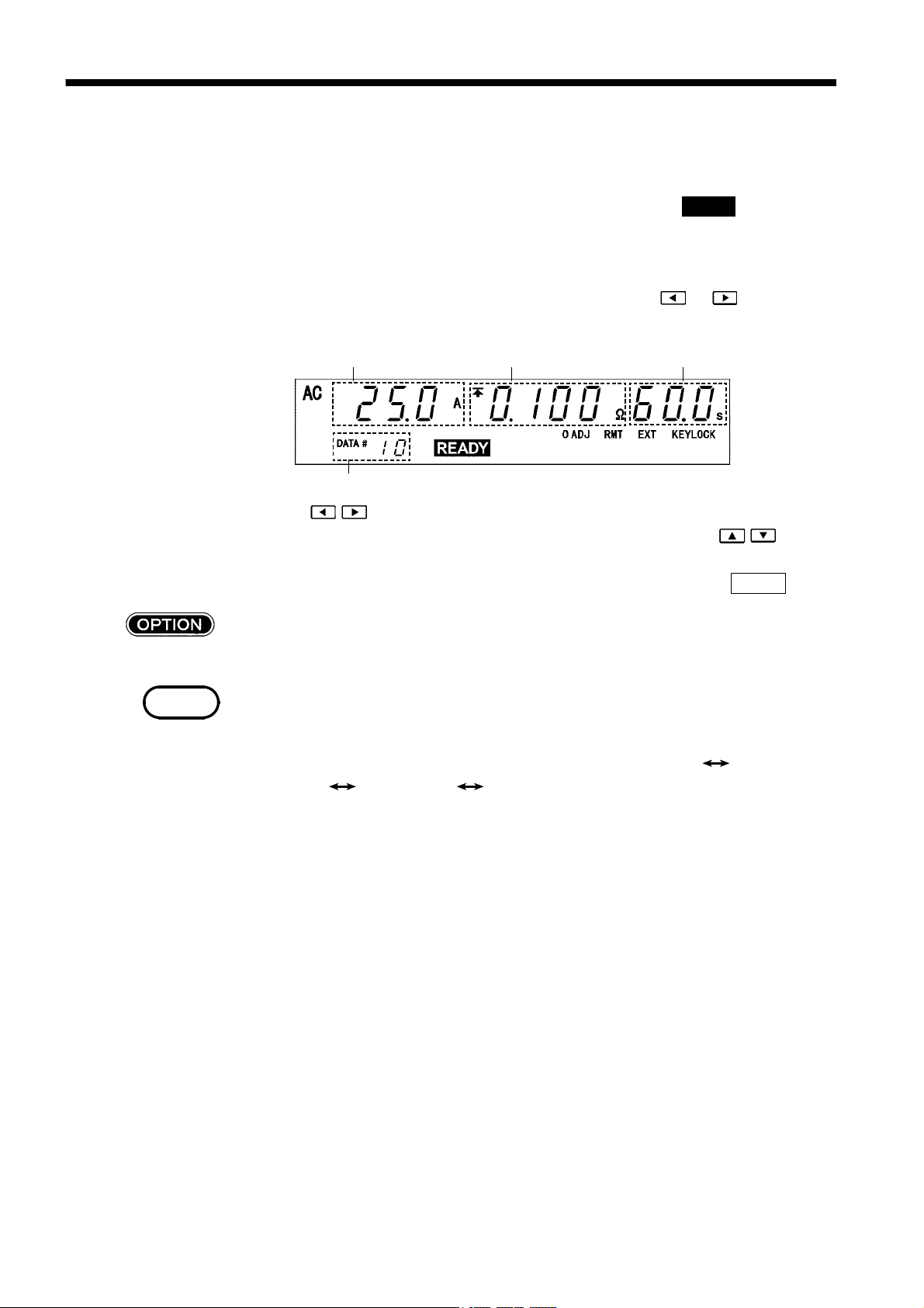
Starting and completing settings
Display the flashing cursor to change set values. Press the
display the flashing cursor with the output current value.
or key to
NOTE
Output current value
Output current frequency or test data count
Press the
/ keys to move the flashing cursor through different settings when
Maximum (minimum) test value
it is lit till the cursor reaches the value to be re-set. Then, press the
Testing time
/ keys to
change the settings.
To erase the flashing cursor, or when settings are complete, press the
STOP
key.
The set values can be printed using the printer output function (see Section4.11).
・
The value range that can be set on the flashing cursor depends on the minimum
test value, the state of the endless timer, and the test data count value on optional
settings.
The range set at the factory is as follows: Output current value
test value
・
If STOP signal (key, external I/O, communication) is input, you cannot perform
Testing time Output frequency.
Maximum
the test even though the READY lights.
────────────────────────────────────────────────────
3.2 Making Testing Arrangements (in READY State)
Page 30
23
────────────────────────────────────────────────────
3.2.1 Setting Output Current Values
(1) If no flashing cursor is displayed in the READY state, press either the key or
the
key to display the cursor while the output current value is lit.
(2) Change output current values using the
/ keys. The value changes in 0.1 A
increments.
To change the value by 1.0 A, press
SHIFT
+ / keys.
The output current value can be set from 3.0 A to 31.0 A.
(3) When settings are complete, press the
STOP
key.
The output current can be changed using the current changeability in TEST
State (see Section 4.8).
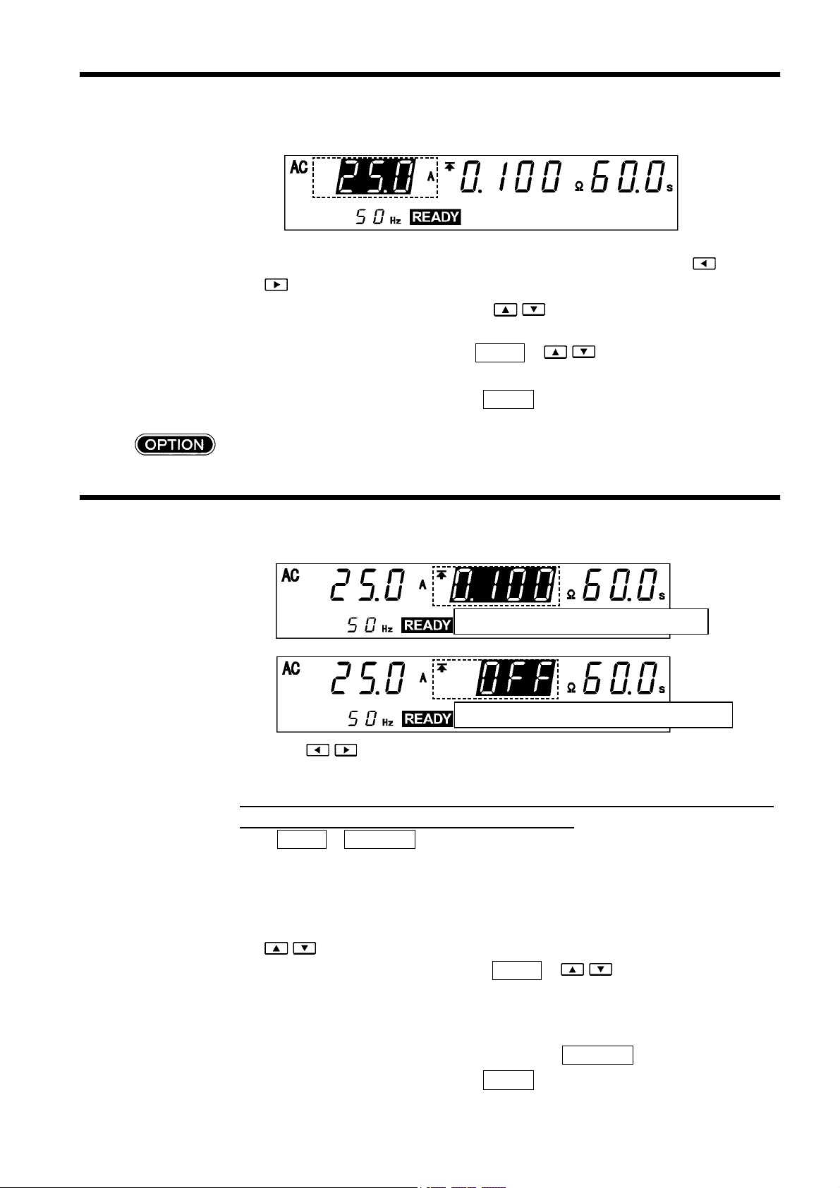
3.2.2 Setting the Maximum (Minimum) Test Value
The maximum resistance is displayed.
The maximum resistance is not displayed.
(1) Using the
/ keys, move the flashing cursor to the maximum test value.
(2) Switching between resistance and voltage indicators
The maximum test value can be set for both resistance and voltage. If both are set,
only the one displayed in READY state is activated.
Press
SHIFT
+
ON/OFF
(Ω/V) to switch between resistance and voltage
indicators. (This key operation is valid no matter where the flashing cursor is
located.)
(3) Setting the maximum test value
After selecting between the resistance and the voltage, set the maximum value using
the
To change the value by 0.010 Ω,press
/ keys.
SHIFT
+ / keys (0.10 V when the
voltage is displayed).
Resistance may be set from 0.000 Ω to 2.000 Ω, while voltage may be set from
0.00 V to 6.00 V.
If no maximum test value is required, turn off the
(4) When settings are complete, press the
────────────────────────────────────────────────────
3.2 Making Testing Arrangements (in READY State)
STOP
ON/OFF
key.
key.
Page 31

24
────────────────────────────────────────────────────
The minimum test value can be set using the minimum test value setting
function (see Section 4.4).
Once a minimum test value is set, both minimum and maximum values are
provided for resistance or voltage.
To set a minimum test value, activate the optional minimum test value setting
function.
The minimum resistance is displayed.
To set a minimum test value, do the same as when setting a maximum test value.
The minimum test value must be smaller than the maximum test value. Otherwise,
key is pressed.
NOTE
a test will not start when the
・
Four values may be set - the maximum and minimum test values for resistance
START
and maximum and minimum test values for voltage. However, the reference
value for testing is expressed in the unit displayed in TEST state. That is,
screening is conducted using the reference resistance when resistance is displayed,
and reference voltage when voltage is displayed.
・
A combination of resistance and voltage values (such as a maximum resistance
value and a minimum voltage value) can't be tested.
3.2.3 Setting the Testing Time
(1) Using the
(2) Set the testing time using the
With time set at 0.5 s to 99.9 s, the time changes in 0.1 s increments (1 s
increments when the set time scale is 100 s to 999 s).
With time set at 0.5 s to 99.9 s, press
s increments (10 s increments when the set time scale is 100 s to 999 s).
Settings may be made along a scale ranging from 0.5 s to 999 s (in gradations of
0.1 s for the range 0.5 s to 99.9 s and 1 s for the range 100 s to 999 s).
If no testing time is required, turn off the
/ keys, move the flashing cursor to the testing time.
/ keys.
SHIFT
The testing time is not displayed.
+ / . The time changes in 1.0
ON/OFF
key.
(3) When settings are complete, press the
────────────────────────────────────────────────────
3.2 Making Testing Arrangements (in READY State)
STOP
key.
Page 32

25
────────────────────────────────────────────────────
The endless timer function allows continuous testing regardless of the
testing time set (see Section 4.5).
NOTE
The test automatically stops after the lapse of 999 s while the testing time setting
can be disabled by using the
ON/OFF
key.
3.2.4 Setting the Output Current Frequency (in READY State)
If the optional test data count function is activated, the output current frequency is
not displayed in READY state. To display or modify the output current frequency
in READY state, change the setting for the test data count to "0: Not set."
(1) Using the
(2) Change the output current frequency (50/60 Hz) using the
(3) When settings are complete, press the
The frequency can also be changed using the output current frequency
switching function (see Section 4.1).
/ keys, move the flashing cursor to the testing time.
/ keys.
STOP
key.
NOTE
Changing the frequency in READY state automatically changes the contents of the
optional output current frequency switching function.
3.2.5 Setting the Test Data Count (in READY State)
The number of test data may be changed in the READY state.
For the test data count setting, see Section 4.6, "Test Data Count Function."
NOTE
(1) Using the
(2) Change the test data count using the
(3) When settings are complete, press the
If you make settings for the test data count, output frequency cannot be changed in
the READY state. To change output frequency, use the optional function setting
screen.
/ keys, move the flashing cursor to the test data count.
/ keys.
STOP
key.
────────────────────────────────────────────────────
3.2 Making Testing Arrangements (in READY State)
Page 33

26
────────────────────────────────────────────────────
3.3 Initial Settings for Optional Functions
Press
SHIFT
+
STOP
while in READY state to display the Optional function
setting screen.
Setting the optional functions allows testing under various conditions.
Settings can be made for the following eleven optional functions. One number is
assigned to each function. Settings are made by changing the number by using the
/ keys.
For more information on the settings, see Chapter 4, "Optional Functions."
1 2 3 4 5 6 7 8 9 10 11
The optional functions of the 3157 are factory-preset to the following settings:
Setting item Initial setting
1
Switching the output current
frequency
PASS/FAIL HOLD function
2
HOLD function
3
Setting the minimum test value
4
Endless timer function
5
Test data count
6
Setting the buzzer
7
Changing currents in TEST state
8
Momentary OUT
9
Test mode
10
Setting the printer output
11
0:50Hz
0: PASS not held, FAIL held
0: Not held
0: Not set
0: Not set
0: Not set
0: ON at screening, ON at error
0: Not changeable
0: Not set
0: Soft start mode
0: Not used
NOTE
・
To reset the system, turn on power while pressing the
SHIFT
key. Once the
system is reset, settings for the optional functions and the recorded parameters
will return to their default values (factory-preset values). For more information,
see Section 7.5, "Resetting the System."
・
If STOP signal (key, external I/O, communication) is input, you cannot perform
the test even though the READY lights.
────────────────────────────────────────────────────
3.3 Initial Settings for Optional Functions
Page 34

27
────────────────────────────────────────────────────
3.4 Zero Adjustment Function
Measurements may be affected by a voltage drop in the probe. Zero adjustment is
necessary for accurate measurement, especially when measuring with two terminals
using the short bar. The 0ADJ lamp is lit while the zero adjustment function is
active. Following zero adjustment, the probe's voltage drop is accounted for in
returning measurement data. Note that the zero adjustment function is automatically
disabled if the output current value is changed or when setting data is loaded.
Zero adjustment procedure
(1) Confirm that the unit is in READY state, then short-circuit the probe.
(2) Set an output current value. The value set must be the same as the one used in the
test.
(3) Press the
0ADJ
executed.
Note that a preset current is output during zero adjustment.
Zero adjustment is completed in about 3 seconds. On completion, the unit enters
READY state, and the 0ADJ lamp lights.
key; 0ADJ lamp starts flashing and then zero adjustment is
NOTE
Zero adjustment active
Zero adjustment completed
Zero adjustment is possible within a range equivalent to a resistance between 0.000
Ω and 0.100 Ω, on either the voltage or resistance indicator. If the measured value
falls outside this range, either the resistance value or the voltage value will blink,
and the unit will enter READY state.
Canceling zero adjustments
To disable zero adjustment function, press the
0ADJ
key while it is active. When
the zero adjustment function is inactivated, the 0ADJ lamp goes out, indicating that
the function is inactive. This function is automatically inactivated when the output
current value is changed or when setting data is loaded.
・
The zero adjustment function will not be inactivated, even if you change the
output current by selecting "1: Changeable" on the optional "Current
Changeability in TEST State." Note that if the zero adjustment function is active,
changing the output current value may produce inaccurate results.
・
Current outputs will soft-start during zero adjustment, regardless of the setting for
"Test mode" on the optional function (see Section 4.10.1, "Soft Start Mode").
────────────────────────────────────────────────────
3.4 Zero Adjustment Function
Page 35

28
────────────────────────────────────────────────────
3.5 Key-lock Function
This function is used to keep lock the current set values. It inactivates all keys
except the
START
key,
STOP
KEYLOCK lamp is lit while the key-lock function is active.
Setting and inactivating the key-lock function
To activate the key-lock function, press
To inactivate the key-lock function, press
active.
key, and the resistance/voltage switch. The
Key-lock indicator
SHIFT
SHIFT
+
0ADJ
+
0ADJ
.
while the function is
NOTE
NOTE
Even when the key-lock function is activated, the external switch and the start and
stop signals on the external I/O terminal remain active.
How to inactivate key-lock function in REMOTE state
Once interface communication starts in REMOTE state (the RMT lamp lights), all
keys except the
STOP
To inactivate the REMOTE state, press
key are inactivated.
SHIFT
Remote indicator
+
0ADJ
(LOCK).
Even in REMOTE state, the external switch and the start and stop signals on the
external I/O terminal remain active.
────────────────────────────────────────────────────
3.5 Key-lock Function
Page 36

29
────────────────────────────────────────────────────
3.6 Examples of Settings
Output current value set: 25.0 A, Maximum test value: 0.100 Ω, Testing time:
1minute.
Assume that "0: not set" is selected for "Minimum test value setting," "Timer
setting," and "Test data count" on the optional functions.
The following provides an example of changing set values.
Values currently set
Values to be set
Output current value 30.0 A Output current value 25.0 A
Maximum test value 0.050 Ω Maximum test value 0.100 Ω
Testing time 10.0 s Testing time 60.0 s
(1) Setting output current values
Using the
/ keys, move the flashing cursor to the output current value.
Using the / keys, set "Output current value" to 25.0 A.
To change the value by 1.0 A, press
In this example, press the
key five times while holding down the
SHIFT
+ / keys.
SHIFT
set the output current value to 25.0 A.
key to
(2) Setting the maximum test value
Using the
key, move the flashing cursor to the maximum test value.
In this example, "Maximum test value" is preset to the resistance value.
Using the
To change the value by 0.010 Ω,press
/ keys, set "Maximum test value" to 0.100 Ω.
SHIFT
+ / keys (0.10 V when the
voltage is displayed).
In this example, press the
key five times while holding down the
SHIFT
key to
set the maximum test value to 0.100 Ω.
────────────────────────────────────────────────────
3.6 Examples of Settings
Page 37

30
────────────────────────────────────────────────────
When the voltage indicator is displayed, or to set in a voltage value, first switch to
the resistance indicator, then set the maximum and minimum test values.
Press
SHIFT
+
ON/OFF
(Ω/V) to switch between resistance and voltage
indicators.
(3) Setting the testing time
Using the
key, move the flashing cursor to the testing time.
Using the / keys, set "Testing time" to 60.0 s.
To change the time by 1.0 s, press
SHIFT
+ / keys.
NOTE
The new parameters following setting are shown below:
Output current value 25.0 A
Maximum test value 0.100 Ω
Testing time 60.0 s
Press the
START
key while in this state. The unit enters TEST state to begin
testing.
Press the
STOP
key to finalize the test parameters. The flashing cursor
disappears.
Press the
or key to restore the flashing cursor and allow the test parameters
to be changed.
Even if "Minimum test value setting" on the optional function is active, you can get
the same results obtained in the example above by moving the flashing cursor to the
minimum test value and turning it off with the
ON/OFF
key.
Output current value: 25.0 A, Maximum test value: 0.100 Ω, Minimum test value:
OFF, Testing time: 60.0 s.
────────────────────────────────────────────────────
3.6 Examples of Settings
Page 38

31
────────────────────────────────────────────────────
3.7 Starting a Test
WARNING
NOTE
To avoid electrical accidents, confirm that all connections are secure.
The increased resistance of loose connections can lead to
overheating and fire.
To avoid burns, never touch the output current terminal, probe tip, or
contact point while testing (i.e., in TEST state).
Take particular care to avoid touching the tip of the current
application probe, which may be quite hot when operating, due to its
small surface area.
・
The soft start mode is active only with a load 0.200 Ω or less. If the load
exceeds this value, the state of connection of the probe is not known, and a test
cannot be started. In this case, set the test mode to normal mode.
・
Priority for control of the
START
key is in the following order: the external
switch, the external I/O, and the front panel of the unit. Connecting the switch
signal line plug disables the
START
key on the front panel of the unit and the
start signal for the external I/O.
Normally, the 9296 CURRENT PROBE should be connected to the protection ground
terminal on the equipment being tested. Connect the probe securely, so that it's not
easily dislodged. During current output, take care to ensure that adjacent probes do
not touch, as this may result in a short-circuit. In most cases, the 9297 CURRENT
APPLY PROBE is connected to a test point on the equipment being tested.
Starting a test
The test start procedure varies according to the test mode setting. The unit is
initially set to Soft start mode. For more information, see Section 4.10, "Setting the
Test Mode."
Depending on the output current value and the state of the test object, it will generally
takes about 2 seconds to output the set current. After a while, the output current
value equals the set current value
1 A, and the test screening function activates.
(1) Set the appropriate parameters in the READY state.
(2) Press the
START
key to start the test. If the probe is detached from the measured
object, the test will not start, and the unit will enter the stand-by state (as indicated
by a blinking
TEST
lamp). If this state continues for more than 30 seconds, the
unit returns to the READY state. The test begins when the probe is connected to
the measured object.
(3) The TEST lamp lights when the unit enters TEST state. While the TEST lamp is lit,
be careful not to cause electrical shock by touching the terminal or other parts
through which the current is passing.
(4) If the probe is detached from the measured object during testing, the FAIL lamp
lights together with the UPPER and the LOWER lamps, and the unit enters FAIL
state.
(5) To end the test normally, the probe must contact the measured object throughout the
test.
────────────────────────────────────────────────────
3.7 Starting a Test
Page 39

32
────────────────────────────────────────────────────
Forcible ending of a test
To perform forcible ending of a test, press the
STOP
key. This stops current
output, and the unit enters READY state. No screening operation is performed.
The value at which to forcibly end the test can be held using the hold function
(see Section 4.3).
Failure to start a test
The following cases may make prevent starting a test. In case of failure, check the
settings and reset parameters, if necessary.
(1) The maximum test value is lower than the minimum test value:
After the minimum test value flickers, the unit returns to the READY state. Reset
the maximum or minimum test values.
(2) The output current value is lower than the output current set value:
・
The probe can be disconnected from the tested equipment.
Never attempt to reconnect the probe before the unit returns to READY state.
Sparks may be given off. Before reconnecting, make sure the unit has returned to
READY state.
・
The load resistance may exceed the output capacity of this unit.
In this case, the
FAIL
lamp lights together with the
UPPER
and the
LOWER
lamps, and the unit enters FAIL state.
────────────────────────────────────────────────────
3.7 Starting a Test
Page 40

33
────────────────────────────────────────────────────
Measurement range
Load resistance
1.8
1.5
1.0
0.5
0
Measurement range
0
10 20 30
Open terminal voltage 6 V line
Maximum output power 130 VA line
At an output of 6 A,
6 (V) / 6 (A) = 1.0 (Ω)
from the 6 V line
At an output of 25 A,
130 (VA) / 25
2(A2
) = 0.208 (Ω)
from the 130 VA line
Output current (A)
────────────────────────────────────────────────────
3.7 Starting a Test
Page 41

34
────────────────────────────────────────────────────
3.8 Testing (in TEST State)
TEST state indicates that the unit is performing a test. Be careful not to cause
electrical shock by touching the terminal or other parts though which the current
(the value of which has been set in READY state) is passing.
31 2 4
5 6
1
Measured current value
Indicates the current value being output.
The output current can be changed using the current changeability in TEST
State (see Section 4.8).
2
Maximum value icon and minimum value icon
The symbol
appears when the maximum test value is set, and the symbol
appears when the minimum value is set.
Measured voltage value and measured resistance value
3
The measured voltage value is displayed if the voltage indicator is selected and the
measured resistance value is displayed if the resistance indicator is selected. Press
SHIFT
+
ON/OFF
(Ω/V) to switch between resistance and voltage indicators.
Only the indicators are switched. The maximum and minimum test values are not
changed.
Testing time elapsed
4
When the testing time is set, countdown starts from the time set, and is displayed.
When the testing time is set to OFF, the time elapsed after the start of the test is
displayed. Once elapsed testing time reaches 999 s, the unit completes the test and
returns to READY state. If either the maximum or minimum test value has been
set, the unit enters PASS state.
The endless timer function allows continuous testing regardless of the
testing time set (see Section 4.5).
5
Data count indicator
Lights when the optional test data count function is set to "1: Set."
Test data count (output current frequency)
6
5
Displays test data when the data count indicator described in
above is lit or the
output frequency.
────────────────────────────────────────────────────
3.8 Testing (in TEST State)
Page 42

35
────────────────────────────────────────────────────
3.9 Screening (in PASS State)
The unit enters PASS state when either the maximum or minimum test value is set,
and when the test is completed. The
displaying the value established at the end of the testing period. The PASS state
screen is displayed for about 0.5 second before the unit resumes READY state.
The PASS state is held using the PASS/FAIL HOLD function (see Section 4.2).
The test data count can be displayed using the test data count function (see Section
4.6).
The test result can be printed using the printer output function (see Section 4.11).
1 42 3
PASS
lamp lights while in PASS state,
5 6
1
Measured current value at the end of a test
Displays the current value being output at the end of the test.
2
Maximum value icon and minimum value icon
The symbol
appears when the maximum test value is set, and the symbol
appears when the minimum value is set.
Measured voltage value and measured resistance value at the end of a test
3
The measured voltage value is displayed if the voltage indicator is selected and the
measured resistance value is displayed if the resistance indicator is selected. Press
SHIFT
4
Test completion time
+
ON/OFF
(Ω/V) to switch between resistance and voltage indicators.
Displays the time in which the test has been completed. In PASS state, "0.0s"is
displayed.
Test data count indicator
5
Lights when the optional test data count function is set to "1: Set."
6
Test data count (output current frequency)
5
Displays test data when the data count indicator described in
above is lit or the
output frequency.
────────────────────────────────────────────────────
3.9 Screening (in PASS State)
Page 43

36
────────────────────────────────────────────────────
3.10 Screening (in FAIL State)
The unit enters FAIL state if the measured value deviates from the maximum (or
minimum) test value set.
The FAIL state indicates the time at which the measured value deviated from the
maximum (or minimum) value. The FAIL lamp lights together with the UPPER or
LOWER
the
lamp while in FAIL state (together with the
lamps if the set current cannot be output).
The FAIL state screen is displayed for about 1 second before the unit resumes
READY state.
The FAIL state is held using the PASS/FAIL HOLD function (see Section 4.2).
The test data count can be displayed using the test data count function (see Section
4.6).
The test result can be printed using the printer output function (see Section 4.11).
UPPER
and the
LOWER
4
5 6
1
Measured current value at the end of a test
31 2
Displays the current value being output at the end of the test.
Maximum value icon and minimum value icon
2
The symbol
appears when the maximum test value is set, and the symbol
appears when the minimum value is set.
Measured voltage value and measured resistance value at the end of a test
3
The measured voltage value is displayed if the voltage indicator is selected and the
measured resistance value is displayed if the resistance indicator is selected. Press
SHIFT
Test completion time
4
+
ON/OFF
(Ω/V) to switch between resistance and voltage indicators.
If the testing time is set in FAIL state, the testing time elapsed displays the set
testing time remaining.
When the testing time is set to OFF, the elapsed time is displayed.
Test data count indicator
5
Lights when the optional test data count function is set to "1: Set."
Test data count (output current frequency)
6
5
Displays test data when the data count indicator described in
above is lit or the
output frequency.
────────────────────────────────────────────────────
3.10 Screening (in FAIL State)
Page 44

37
────────────────────────────────────────────────────
Chapter 4
Optional Functions
Setting the optional functions allows testing under various conditions.
Settings can be made for the following eleven optional functions. One number is
assigned to each function. Settings are made by changing the number by moving
the cursor key.
Since improper settings can produce inaccurate results, this chapter explains the
correct way to make settings. Please read it carefully.
Entering the Optional function setting screen
Press
setting screen.
SHIFT
+
STOP
while in READY state to display the Optional function
1 2 3 4 5 6 7 8 9 10 11
Setting optional functions
Use the
Use the
To complete the optional settings, press
READY state.
Press the
state without finalizing settings.
/ keys to move the flashing cursor to the target function.
/ keys to set a value at the flashing cursor location.
SHIFT
STOP
key to abort the setting process. The unit reverts to the READY
+
STOP
. The unit reverts to the
────────────────────────────────────────────────────
Page 45

38
────────────────────────────────────────────────────
The following describes the numbers corresponding to the functions. For additional
information, see Section APPINDIX 2, "Table of Optional Functions."
1
Switching the output current frequency
Switches output current frequencies (50 Hz or 60 Hz).
When the test data count is at "0: Not set," the frequency is displayed in the
READY state.
Selection
2
PASS/FAIL hold function
0: 50 Hz, 1:60Hz
This function retains PASS and FAIL states to help verify the value screened
in the test.
Selection
0: PASS not held, FAIL held
1: PASS held, FAIL held
2: PASS not held, FAIL not held
3: PASS held, FAIL not held
3
Hold function
When the hold function is set in the following cases, the current state is
retained:
・
Following selection of only the test time, some time has elapsed without
setting the maximum or minimum test value.
・
Press the
Selection
4
Setting minimum test value
STOP
0: Not held, 1: Held
key to cancel the test in progress.
The minimum test value can be set as a test parameter.
Selection
5
Endless timer function
0: Not set, 1:Set
If this function is not selected, the test ends after 999 s, after which the test
time is set to OFF in the READY state. Select this function to continue until
it returns a FAIL state, or until you press the
Selection
6
Test data count function
0: Not set, 1:Set
STOP
key.
The test data count function can be preset.
This function counts the number of tests, and is used when testing a large
number of points for a single measured object.
Selection
0: Not set, 1:Set
────────────────────────────────────────────────────
Page 46

39
────────────────────────────────────────────────────
7
Buzzer setting
The buzzer ON/OFF may be set in the PASS, FAIL, error state, and other
states.
Selection
0: ON at screening, ON at error
1: OFF at screening, OFF at error
2: OFF at screening, ON at error
3: ON at screening, OFF at error
8
Changing the current value in TEST state
In TEST state, the current value can be changed during output by pressing the
/ keys.
Selection
9
Momentary OUT
0: Not changeable, 1: Changeable
The momentary OUT function allows current output only while the
key is held down. Once this function is set, working with the 9297
CURRENT APPLY PROBE requires different procedures.
Selection
0: Not set (Trigger operation),
1: Set (Momentary OUT operation)
10
Test mode
Soft start mode, normal mode and continuous test mode can be set.
For more information, see Section 4.10, "Test mode."
START
Selection
11
Printer output
0: Soft start mode, 1: Normal mode, 2: Continuous test mode
You can print test parameters and results with the optional 9442 PRINTER.
This printer offers the following two print modes.
Selection
0: Not used (Initial setting)
1: Automatically print for PASS/FAIL screening.
2: Print selectively when the PASS/FAIL state is held.
────────────────────────────────────────────────────
Page 47

40
────────────────────────────────────────────────────
4.1 Switching the Output Current Frequency
Changes the output current frequency. When the optional test data count function
is set to "1: Not set," the output current frequency set in the READY state is
displayed and can be changed. If you change the frequency in the READY state,
the output current frequency can be changed automatically in the optional function
setting screen.
Setting procedure
NOTE
(1) Press
SHIFT
+
STOP
while in READY state to display the Optional function
setting screen.
(2) Use the
/ keys to move the flashing cursor to the position shown in the
figure.
(3) Use the
/ keys to set a value at the flashing cursor location.
0: 50 Hz (Initial setting)
1:60Hz
(4) To complete the optional settings, press
SHIFT
+
STOP
. The unit reverts to the
READY state.
Setting the optional test data count function prevents display of the output current
frequency in the READY state. To display and change the frequency in the
READY state, set the test data count function to "1: Not set."
────────────────────────────────────────────────────
4.1 Switching the Output Current Frequency
Page 48

41
────────────────────────────────────────────────────
4.2 PASS/FAIL Hold Function
If the maximum or minimum value has been set, this function retains the value for
the PASS or FAIL state on test completion. If the PASS or FAIL hold function is
not selected, the test result is displayed for approximately 0.5 seconds for PASS and
approximately 1 second for FAIL before the unit reverts to the READY state.
To check test results, press the
SHIFT
+
ON/OFF
switch the display between resistance and voltage. The conditions at which the
settings are made do not change, even after switching.
To inactivate the hold function, press the
STOP
READY state.
Setting procedure
(Ω/V). This allows you to
key. The unit reverts to the
NOTE
(1) Press
SHIFT
+
STOP
while in READY state to display the Optional function
setting screen.
(2) Use the
/ keys to move the flashing cursor to the position shown in the
figure.
(3) Use the
/ keys to set a value at the flashing cursor location.
0: PASS not held, FAIL held (Initial setting)
1: PASS held, FAIL held
2: PASS not held, FAIL not held
3: PASS held, FAIL not held
(4) To complete the optional settings, press
SHIFT
+
. The unit reverts to the
STOP
READY state.
・
Even when the key-lock function is activated, to switch the display between
resistance and voltage, press
・
When continuous test mode is selected on the optional function, the PASS/FAIL
SHIFT
+
ON/OFF
(Ω/V).
hold function works somewhat differently. For more information, see Section
4.10.3, "Continuous Test Mode."
────────────────────────────────────────────────────
4.2 PASS/FAIL Hold Function
Page 49

42
────────────────────────────────────────────────────
4.3 HOLD Function
If a test is conducted with both the maximum test value and the minimum test value
turned off, the unit enters the READY state as soon as test time elapses (after the
lapse of 999 s if the testing time is set to OFF), or if the test is aborted with the
STOP
To check test results, press the
switch the display between resistance and voltage. The conditions at which the
settings are made do not change, even after switching.
To inactivate the hold function, press the
READY state.
Setting procedure
key. Select "1: Held" to retain the last value and to check test results.
SHIFT
+
STOP
ON/OFF
(Ω/V). This allows you to
key. The unit reverts to the
NOTE
(1) Press
SHIFT
+
STOP
while in READY state to display the Optional function
setting screen.
(2) Use the
/ keys to move the flashing cursor to the position shown in the
figure.
(3) Use the
/ keys to set a value at the flashing cursor location.
0: Not held (Initial setting)
1: Held
(4) To complete the optional settings, press
SHIFT
+
STOP
. The unit reverts to the
READY state.
・
Even when the key-lock function is activated, to switch the display between
resistance and voltage, press
・
When continuous test mode is selected on the optional function, the hold function
SHIFT
+
ON/OFF
(Ω/V).
works somewhat differently. For more information, see Section 4.10.3,
"Continuous Test Mode."
────────────────────────────────────────────────────
4.3 HOLD Function
Page 50

43
────────────────────────────────────────────────────
Differences between PASS/FAIL hold and hold functions
・
Unless the test reference value is set, PASS/FAIL screening is not performed.
・
If a test is conducted with both the maximum test value and the minimum test
value turned off, the unit enters the READY state as soon as test time elapses
(after the lapse of 999 s if the testing time is set to OFF). If the hold function is
set to "ON," the last value is retained. This function is disabled if you use the
endless timer.
Press the START key to start a test.
OFF
Press the STOP key to abort a test.
determination
HOLD function
ON
Test time elapses.
determination
Printer output setting
The test result is automatically printed with "1."
Test data count function setting
The number of test data is renewed with "1."
OFF
FAIL hold functionPASS hold function
ON ON
The PASS or FAIL state is held.
Printer output setting
The test result can be printed by
holding down the STOP
with "2."
key
The value at the time when
the test was aborted is held.
OFF
Press the STOP key to inactivate the hold function.
・
NOTE
To print test results with an optional 9442 PRINTER with the printer output
function set to "2," the unit must be in a PASS/FAIL hold state.
────────────────────────────────────────────────────
4.3 HOLD Function
Page 51

44
────────────────────────────────────────────────────
4.4 Setting the Minimum Test Value
If the minimum test value is set to "0: Not set," the flashing cursor does not move
to the minimum test value, thus disabling test settings.
If the minimum test value is set to "1: Set," both maximum and minimum test
values may be set.
Even selecting OFF with the
ON/OFF
in the test, but the flashing cursor will move to the minimum test value. Select "0:
Not set," unless the minimum test value is required.
These settings are saved or loaded along with the test data.
Setting procedure
key will not reflect the minimum test value
NOTE
(1) Press
SHIFT
+
STOP
while in READY state to display the Optional function
setting screen.
(2) Use the
/ keys to move the flashing cursor to the position shown in the
figure.
(3) Use the
/ keys to set a value at the flashing cursor location.
0: Not set (Initial setting)
1:Set
(4) To complete the optional settings, press
SHIFT
+
STOP
. The unit reverts to the
READY state.
・
The maximum and minimum resistance values and maximum and minimum
voltage values can be set independently. The value displayed just before you
enter the TEST state serves as the reference test value; if a resistance value is
displayed, the reference resistance value is used for screening. Similarly, the
voltage resistance value is used if a voltage value is displayed.
・
A combination of resistance and voltage values (e.g. the maximum resistance
value and the minimum voltage) is not possible.
────────────────────────────────────────────────────
4.4 Setting the Minimum Test Value
Page 52

45
────────────────────────────────────────────────────
4.5 Endless Timer Function
In setting the endless timer, if "1: Set" is selected, currents are continually output in
the TEST status regardless of the test time elapsed. In the READY state "- - -" is
displayed for the test time, and the cursor stops moving to "Test Time."
To end the test, the unit must enter the FAIL state or the
pressed.
These settings are saved or loaded along with the test data.
Setting procedure
STOP
key must be
(1) Press
SHIFT
+
STOP
while in READY state to display the Optional function
setting screen.
(2) Use the
/ keys to move the flashing cursor to the position shown in the
figure.
(3) Use the
/ keys to set a value at the flashing cursor location.
0: Not set (Initial setting)
1:Set
(4) To complete the optional settings, press
READY state.
SHIFT
+
During setting of the endless timer
. The unit reverts to the
STOP
NOTE
If the test time is set to OFF with the
ON/OFF
key instead of using the endless
timer function, the test is ended after the test time of 999 s.
────────────────────────────────────────────────────
4.5 Endless Timer Function
Page 53

46
────────────────────────────────────────────────────
4.6 Test Data Count Function
Use the test data count function to display the number of test data.
The test begins with "the number of test data: 1." The number increments by one
each time a test completes. Once the maximum number of data is attained,
counting restarts at "1."
Increase or decrease of the number of test data can be performed in the READY
state, except for the maximum number of test data which cannot be changed. To
change the number of test data in the READY state, see Section 3.2.5, "Setting the
Test Data Count."
Setting procedure
(1) Press
SHIFT
+
STOP
while in READY state to display the Optional function
setting screen.
(2) Use the
/ keys to move the flashing cursor to the position shown in the
figure.
(3) Use the
/ keys to set a value at the flashing cursor location.
0: Not set (Initial setting)
1:Set
(4) Setting the maximum number of test data Select "1: Set" to display the maximum
number of test data.
Maximum number of test data
In this example, the maximum number of test data is set at 17. Counting starts at 1
and ends at 17, after which the number reverts to 1.
To change the maximum number of test data, move the flashing cursor to the test
data count using the
using the
/ keys. To change the number by 10, press
/ keys. Change the maximum number of test data
SHIFT
+ /
keys. The maximum number may be set from 1 to 99.
(5) To complete the optional settings, press
SHIFT
+
STOP
. The unit reverts to the
READY state.
・
NOTE
The data can be renewed as the PASS or FAIL state shifts to the READY state.
To perform PASS/FAIL screening, you must set maximum and minimum test
values and the test time.
・
If the test is stopped with the
STOP
key without performing test screening, as in
the case of aborting a test, the number of test data is not renewed.
・
Output frequency cannot be changed in the READY state if you set the test data
count function. To change the frequency, make your settings in the Optional
function setting screen.
────────────────────────────────────────────────────
4.6 Test Data Count Function
Page 54

47
────────────────────────────────────────────────────
4.7 Buzzer Setting
The buzzer function is enabled in PASS or FAIL state, or when an error occurs with
setting or key operation.
When the buzzer is set to ON, the sound of the buzzer cannot be controlled. The
sound is disabled when the buzzer is set to OFF.
Setting procedure
NOTE
(1) Press
SHIFT
+
STOP
while in READY state to display the Optional function
setting screen.
(2) Use the
/ keys to move the flashing cursor to the position shown in the
figure.
(3) Use the
/ keys to set a value at the flashing cursor location.
0: ON at screening, ON at error (Initial setting)
1: OFF at screening, OFF at error
2: OFF at screening, ON at error
3: ON at screening, OFF at error
(4) To complete the optional settings, press
SHIFT
+
. The unit reverts to the
STOP
READY state.
During screening, the length of time the buzzer sounds depends on the settings for
the PASS and FAIL hold. For more about the PASS and FAIL hold setting, see "4.2
PASS/FAIL Hold Function."
PASS, FAIL hold setting PASS buzzer FAIL buzzer
PASS not held, FAIL held Approx. 0.5 s Until held status is reset.
PASS held, FAIL held Approx. 0.5 s Until held status is reset.
PASS not held, FAIL not held Approx. 0.5 s Approx.1s
PASS held, FAIL not held Approx. 0.5 s Approx.1s
────────────────────────────────────────────────────
4.7 Buzzer Setting
Page 55

48
────────────────────────────────────────────────────
4.8 Changing the Current Value in TEST State
Selecting "1: Changeable" makes it possible to change the output current value
during testing in 0.1 A increments, using the
1.0A,press
SHIFT
+ / keys.
The output current value can be set from 3.0 A to 31.0 A. The value cannot be
changed if the key-lock function remains active.
If the current value is changed in the TEST state, the current value set in the
READY state cannot be changed.
A current value set in the TEST state remains valid until the test is completed.
Selecting "0: Not changeable" disables changing the value, even if you press the
/ keys in the TEST state.
Setting procedure
/ keys. To change the value by
NOTE
(1) Press
SHIFT
+
STOP
while in READY state to display the Optional function
setting screen.
(2) Use the
/ keys to move the flashing cursor to the position shown in the
figure.
(3) Use the
/ keys to set a value at the flashing cursor location.
0: Not changeable (Initial setting)
1: Changeable
(4) To complete the optional settings, press
SHIFT
+
STOP
. The unit reverts to the
READY state.
・
Because the measured current value is displayed after an averaging operation,
there is a brief delay after you press the key before the display reflects the change.
・
The zero adjustment function will not be inactivated, even if you change the
output current. Note that if the zero adjustment function is active, changing the
output current value may produce inaccurate results.
────────────────────────────────────────────────────
4.8 Changing the Current Value in TEST State
Page 56

49
────────────────────────────────────────────────────
4.9 Momentary OUT
The momentary OUT function allows current output only while the
held down. Releasing the
START
key is equivalent to pressing the
START
STOP
and ends the test.
Keep the
START
key depressed until the test time elapses. After the test time
elapses, the unit enters the READY or PASS state, depending on the optional
settings. In either state, the next test will not begin even if the
START
key is held
down.
To start the next test, release, then press the
PASS or FAIL state, cancel the state with the
START
key. When the unit enters the
STOP
key.
If you set the momentary OUT function to "1: Set," a different procedure is required
with the
START
key, the START signal for the external I/O terminal and the 9297
CURRENT APPLY PROBE.
For the 9297 CURRENT APPLY PROBE, selecting "0: Not set" enables trigger
operation, and selecting "1: Set" enables the momentary OUT function.
Setting procedure
(1) Press
SHIFT
+
STOP
while in READY state to display the Optional function
setting screen.
key is
key
NOTE
(2) Use the
/ keys to move the flashing cursor to the position shown in the
figure.
(3) Use the
/ keys to set a value at the flashing cursor location.
0: Not set (Initial setting) (Trigger operation is performed with the 9297.)
1: Set (Momentary OUT operation)
(4) To complete the optional settings, press
SHIFT
+
. The unit reverts to the
STOP
READY state.
・
Priority for control of the
START
key is in the following order: the external
switch, the external I/O, and the front panel of the unit. Connecting the switch
signal line plug disables the
START
key on the front panel of the unit and the
start signal for the external I/O.
・
For the switching probe, you can select between "trigger operation" and
"momentary OUT operation." Note that a different switching procedure is
required for the operations.
・
When the optional continuous test mode is selected, the momentary OUT function
is automatically set to "0."
────────────────────────────────────────────────────
4.9 Momentary OUT
Page 57

50
────────────────────────────────────────────────────
4.9.1 Trigger Operation with Switching Probe
When in the READY state, the push switch performs the same functions as the
START
When not in the READY state, the push switch performs the same functions as the
STOP
the
If the optional PASS/FAIL state hold function is active, pressing the push switch in
either the PASS or FAIL state is equivalent to pressing the
actions canceling the hold state.
key.
key. Pressing the push switch in the TEST state is equivalent to pressing
STOP
key and ends the test.
STOP
key, with both
NOTE
For the switching probe, you can select between "trigger operation" and "momentary
OUT operation." Note that a different switching procedure is required for the
operations.
In setting "momentary OUT," select "1: Not set."
The push switch is turned ON at LO level and OFF at HI level in the timing chart.
Example 1 PASS/FAIL hold function: "1: PASS held, FAIL held"
Endless timer function: "0: Not set"
(1) When the tested sample passes the test:
1. To start the test, press the push switch while in the READY state.
2. The test is complete when the preset test time elapses. The unit enters the PASS
state. Since the PASS hold function is active, the PASS state is retained.
3. To release the hold state, press the push switch. The unit enters the READY
state.
4. To restart the test, press the push switch.
Preset test time
1. 2. 3. 4.
Switch: OFF
Switch: ON
────────────────────────────────────────────────────
4.9 Momentary OUT
Page 58

51
────────────────────────────────────────────────────
(2) When the test is aborted:
1. To start the test, press the push switch while in the READY state.
2. The test is aborted if the push switch is pressed before the preset test time
elapses, with the unit then entering the READY state.
3. To restart the test, press the push switch.
Preset test time
1. 2. 3.
Switch: OFF
Switch: ON
Example 2 PASS/FAIL hold function: "0: PASS not held, FAIL held"
Endless timer function: "0: Not set"
Hold function: "0: Not held"
(1) When the tested sample passes the test:
1. To start the test, press the push switch while in the READY state.
2. The test is complete when the preset test time elapses. The unit enters the PASS
state. Since the PASS hold function is inactive, the unit enters the READY state
in about 0.5 seconds.
3. To restart the test, press the push switch.
Preset test time
1. 2. 3.
Switch: OFF
Switch: ON
(2) When the tested sample fails the test:
1. To start the test, press the push switch while in the READY state.
2. The unit enters the FAIL state. Since the FAIL hold function is active, the FAIL
state is retained.
3. To release the hold state, press the push switch. The unit enters the READY
state.
4. To restart the test, press the push switch.
Preset test time
1. 2. 3. 4.
Switch: OFF
Switch: ON
────────────────────────────────────────────────────
4.9 Momentary OUT
Page 59

52
────────────────────────────────────────────────────
4.9.2 Momentary OUT Operation with Switching Probe
The momentary OUT function allows current output only while the push switch is
held down. Releasing the push switch is equivalent to pressing the
STOP
ends the test.
A test ends when the test time elapses, even if the push switch is held down.
Depending on the settings, the unit enters either the READY or PASS state. The
test also ends if the unit enters the FAIL state during testing, even if you hold down
the push switch.
If the optional PASS/FAIL state hold function is active, pressing the push switch in
either the PASS or FAIL state is equivalent to pressing the
STOP
key, with both
actions canceling the hold state.
key and
NOTE
For the switching probe, you can select between "trigger operation" and "momentary
OUT operation." Note that a different switching procedure is required for the
operations.
In setting "momentary OUT," select "1: Set."
The push switch is turned ON at LO level and OFF at HI level in the timing chart.
Example 1 PASS/FAIL hold function: "1: PASS held, FAIL held"
Endless timer function: "0: Not set"
(1) When the tested sample passes the test:
1. To start the test, press the push switch while in the READY state.
2. Hold down the push switch for the duration of the test. Releasing this switch
will abort the test.
3. The test is complete when the preset test time elapses. The unit enters the PASS
state. Since the PASS hold function is active, the PASS state is retained. In this
state, the push switch may be released. The same state is maintained.
4. To release the hold state, press the push switch. The unit enters the READY
state.
5. To restart the test, press the push switch.
Preset test time
1. 2. 3. 4. 5.
Switch: OFF
Switch: ON
────────────────────────────────────────────────────
4.9 Momentary OUT
Page 60

53
────────────────────────────────────────────────────
(2) When the test is aborted:
1. To start the test, press the push switch while in the READY state. The TEST
state is maintained as long as the push switch is held down.
2. The test is aborted if the push switch is released before the preset test time
elapses, with the unit then entering the READY state.
3. To restart the test, press the push switch.
Preset test time
1. 2. 3.
Switch: OFF
Switch: ON
Example 2 PASS/FAIL hold function: "0: PASS not held, FAIL held"
Endless timer function: "0: Not set"
Hold function: "0: Not held"
(1) When the tested sample passes the test:
1. To start the test, press the push switch while in the READY state.
2. Hold down the push switch for the duration of the test. Releasing this switch
will abort the test.
3. The test is complete when the preset test time elapses. The unit enters the PASS
state. Since the PASS hold function is inactive, the unit enters the READY state
in about 0.5 seconds. In this state, the push switch may be released. The same
state is maintained.
4. To restart the test, press the push switch.
Preset test time
1. 2. 3. 4.
Switch: OFF
Switch: ON
────────────────────────────────────────────────────
4.9 Momentary OUT
Page 61

54
────────────────────────────────────────────────────
(2) When the tested sample fails the test:
1. To start the test, press the push switch while in the READY state.
2. Hold down the push switch for the duration of the test. The unit enters the FAIL
state. Since the FAIL hold function is active, the FAIL state is retained. In this
state, the push switch may be released. The same state is maintained.
3. To release the hold state, press the push switch. The unit enters the READY
state.
4. To restart the test, press the push switch.
Preset test time
State of the unit
1. 2. 3. 4.
Push switch
START
(Start the test)
key
STOP
(Release the
hold state)
key
START
(Start the test)
key
────────────────────────────────────────────────────
4.9 Momentary OUT
Page 62

55
────────────────────────────────────────────────────
4.10 Setting the Test Mode
Soft start mode, normal mode and continuous test mode can be set.
Setting procedure
NOTE
(1) Press
SHIFT
+
STOP
while in READY state to display the Optional function
setting screen.
(2) Use the
/ keys to move the flashing cursor to the position shown in the
figure.
(3) Use the
/ keys to set a value at the flashing cursor location.
0: Soft start mode (Initial setting)
1: Normal mode
2: Continuous test mode
(4) To complete the optional settings, press
SHIFT
+
. The unit reverts to the
STOP
READY state.
When the continuous test mode is selected, the optional momentary OUT function is
automatically set to "0."
4.10.1 Soft Start Mode
NOTE
The soft start mode is active only with a load 0.200 Ω or less. If the load exceeds
this value, the state of connection of the probe is not known, and a test cannot be
started.
This function checks whether the probe is in contact with the measured object by
constantly monitoring the output current value. With this function selected, no
current is output if the test begins with a disconnected probe. When the probe
contacts the measured object, the test begins without sparks. The instant the probe
is detached from the measured object during testing, output current is halted, and
the unit enters the READY state.
(1) Set the appropriate parameters in the READY state.
(2) Press the
START
object, the test will not start, and the unit will enter the stand-by state (as indicated
by a blinking TEST lamp). If this state continues for more than 30 seconds, the
unit returns to the READY state. The test begins when the probe is connected to
the measured object.
(3) If the probe is detached from the measured object during testing, the FAIL lamp
lights together with the UPPER and the LOWER lamps, and the unit enters FAIL
state.
(4) To end the test normally, the probe must contact the measured object throughout the
test.
key to start the test. If the probe is detached from the measured
────────────────────────────────────────────────────
4.10 Setting the Test Mode
Page 63

56
────────────────────────────────────────────────────
Flow of operation in Soft start mode
Press the START key to start a test.
The unit enters the stand-by state
(as indicated by a blinking TEST lamp).
Is the probe
connected to the
measured object?
NO
YES
Press the STOP key to abort a test.
FAIL determination
・
The probe is detached from
・
the measured object.
Test time elapses.
determination
OFF OFF
PASS hold function
FAIL hold function
Press the STOP
・
to abort a test.
More than 30 seconds
・
elapse.
HOLD function
ON
key
OFF
ON ON
Press the
to inactivate the hold
function.
STOP
key
────────────────────────────────────────────────────
4.10 Setting the Test Mode
Page 64

57
────────────────────────────────────────────────────
4.10.2 Normal Mode
Select normal mode if the anticipated load resistance is 0.200 Ω or greater.
In normal mode, press the
START
function is in the stand-by state (as indicated by a blinking
START
key is pressed, the unit enters TEST state.
If the probe is detached from the measured object during testing, the FAIL lamp
lights together with the
UPPER
state.
The unit will not detect the connection state of the probe. To avoid occurrence of
sparks between the probe and the device being tested, make the connections before
pressing the
START
key.
Flow of operation in Normal mode
Press the START key to start a test.
key in READY state while the soft start
TEST
lamp). When the
and the
LOWER
lamps, and the unit enters FAIL
Press the STOP
・
FAIL determinatio
・
The probe is detached from
・
the measured object.
Test time elapses.
determination
OFF OFF
PASS hold function
ON ON
Press the
to inactivate the hold
function.
STOP
key
key to abort a test.
OFF
HOLD function
ON
FAIL hold function
NOTE
────────────────────────────────────────────────────
Select normal mode if the anticipated load resistance is 0.200 Ω or greater.
4.10 Setting the Test Mode
Page 65

58
────────────────────────────────────────────────────
4.10.3 Continuous Test Mode
Unlike the soft start mode, the continuous test mode places the unit into the hold
state if the probe is detached from the measured object, suspending output. To
restart the test, cancel the hold state and connect the probe to the measuring object.
(1) Set the appropriate parameters in the READY state.
(2) Press the
START
object, the test will not start, and the unit will enter the stand-by state (as indicated
by a blinking
unit returns to the READY state. The test begins when the probe is connected to
the measured object.
(3) If the probe is detached from the measured object during testing, the test is aborted.
The unit enters the hold state instead of the READY state.
To end the test normally, the probe must contact the measured object throughout the
test.
When the test finishes, the screening results will determine a state of PASS or
FAIL.
(4) Cancel the hold state. The unit enters the stand-by state (as indicated by a blinking
TEST lamp) preparatory to beginning a test. The values measured in the preceding
test are retained, even in this state.
key to start the test. If the probe is detached from the measured
TEST
lamp). If this state continues for more than 30 seconds, the
NOTE
Canceling hold state
HOLD ON: Press the
STOP
key and detach the probe from the measured object
(the reverse step is allowed).
HOLD OFF: Detach the probe from the measured object.
(5) Connect the probe to begin the next test.
(6) To enter the READY state after testing, press the
STOP
by state (as indicated by the blinking TEST lamp). If you press the
key in the TEST or stand-
STOP
while the unit is in the hold state, the unit will not enter the READY state. This is
because the action is interpreted as canceling the hold state.
・
The values measured in the test are retained by the PASS/FAIL hold function and
the hold function at the end of the testing if the unit is in continuous test mode.
Note that different settings require different methods of canceling.
・
The continuous test mode and the momentary OUT function are not compatible.
If continuous test mode is selected in test mode, the momentary OUT function is
automatically reset to "0."
key
────────────────────────────────────────────────────
4.10 Setting the Test Mode
Page 66

59
────────────────────────────────────────────────────
Flow of operation in Continuous test mode
Press the START key to start a test.
The unit enters the stand-by state (as
indicated by a blinking TEST lamp).
Is the probe
connected to the
measured object?
NO
YES
Press the STOP key to abort a test.
The probe is detached from the measured
object.
determination
Test time elapses.
determination
Press the STOP
・
to abort a test.
More than 30 seconds
・
elapse.
OFF
HOLD function
ON
key
OFF OFF
PASS hold function
ON ON
Detach the probe from the
measured object to inactivate
the hold function.
FAIL hold function
Press the
the probe from the measured object
to inactivate the hold function (the
reverse step is allowed).
STOP
key and detach
────────────────────────────────────────────────────
4.10 Setting the Test Mode
Page 67

60
────────────────────────────────────────────────────
4.11 Printer Output
You can print test parameters and results with the optional 9442 PRINTER. This
printer offers the following two print modes.
When "0: Not used" is selected, the printer will not print, even if connected.
When "1: Automatically print for PASS/FAIL screening" is selected, press the
STOP
The test results are printed automatically when the unit enters the PASS or FAIL
state, whether or not the state is retained.
When "2: Selectively print when the PASS/FAIL state is held" is selected, printing
begins about two seconds after the
hold state. Unless the
PASS/FAIL hold state without printing, and the unit reverts to the READY state.
To print the test results, you must make the appropriate settings to retain either the
PASS or FAIL state, using the PASS/FAIL hold function.
key for about two seconds in the READY state to print the test results.
key is pressed to cancel the PASS/FAIL
STOP
key cancels the
STOP
STOP
key is kept pressed, the
NOTE
Setting procedure
(1) Press
SHIFT
+
STOP
while in READY state to display the Optional function
setting screen.
(2) Use the
/ keys to move the flashing cursor to the position shown in the
figure.
(3) Use the
/ keys to set a value at the flashing cursor location.
0: Not used (Initial setting)
1: Automatically print for PASS/FAIL screening.
2: Print selectively when the PASS/FAIL state is held.
(4) To complete the optional settings, press
SHIFT
+
. The unit reverts to the
STOP
READY state.
・
The printer output settings apply only when the 9593-02 RS-232C INTERFACE
and the 9442 PRINTER are connected. Connect the 9593-02 and the 9442 before
starting up.
For more information on settings, see the accompanying manual and Appendix1,
"Options".
・
If the printer output function is set to "1: Automatically print for PASS/FAIL
screening" and the PASS/FAIL hold function to "PASS/FAIL not held," the PASS
or FAIL state may be verified on the printer, but not on screen.
If the continuous test mode and the test data count mode are set, you can continue
testing as the results print by keeping your hand on the probe.
・
The test parameters cannot be printed using the push switch on the 9297
CURRENT APPLY PROBE.
────────────────────────────────────────────────────
4.11 Printer Output
Page 68

61
────────────────────────────────────────────────────
Example of printing
Example of set value printing
Example of test result printing
Set value printing
SETTING
CURRENT
UPPER
LOWER
TIMER
MAX DATA #
Test result printing
HIOKI 3157
GROUNDING
HiTESTER
DATA #
JUDGEMENT Test result
RESISTANCE
CURRENT
Actual size
Shows test parameter printing.
Set current value and output current frequency
Maximum test value
Minimum test value
"---" is printed if the optional minimum test value setting
function is set to "0: Not set."
Testing Time
"---" is printed if the optional endless timer function is set to
"1: Set."
Maximum number of test data (Not printed for OFF)
Model name
This is printed if the test data count function is not used or
if the number of test data is 1.)
Number of test data and maximum number of test data
These are not printed if the test data count function is not
used.
PASS, UPPER FAIL or LOWER FAIL is printed. The
elapsed time and testing time are also printed for FAIL.
Measured resistance value and measured voltage value at the
end of a test
Measured current value and frequency at the end of a test
────────────────────────────────────────────────────
4.11 Printer Output
Page 69

62
────────────────────────────────────────────────────
4.12 Example of Optional Function Settings
We assume that the 3157 is in the READY state and that the minimum test value
setting function and the test data count function are inactive.
The following example shows how to set the number of test data to "5," after
activating the minimum test value setting and test data count functions.
Since the minimum test value setting function is disabled, the flashing cursor does
not move to the minimum test value. Because the test data count function is also
inactive, the output current frequency is displayed.
(1) Press
(2) To change the setting of the minimum test value, move the flashing cursor to the
fourth number from the left. In the optional function setting screen, the flashing
cursor will first appear at the leftmost position. Press the
move to the fourth number.
(3) "Minimum test value setting" is set to "0: Not set." Using the
change the setting to "1: Set."
SHIFT
+
STOP
to display the Optional function setting screen.
key three times to
/ keys,
────────────────────────────────────────────────────
4.12 Example of Optional Function Settings
Page 70

63
────────────────────────────────────────────────────
(4) Next, using the / keys, change "Test data count" from "0: Set" to "1: Not
set." In "Test data count," change the sixth number from the left to "1."
When "Test data count" is activated, the screen shifts to allow you to set a
maximum value for the number of test data. In this example, the current maximum
number is "1."
(5) To change the maximum number of test data to "5," move the flashing cursor by
using the
/ keys to the maximum value in "Number of test data."
Use the
this example, press the
(6) Press
/ keys to change the maximum value for the number of test data. In
key four times.
SHIFT
+
STOP
. This operation finalizes the optional settings, after which
the unit reverts to the READY state.
After "Test data count" is set, the output current frequency is replaced by "Number
of test data."
────────────────────────────────────────────────────
4.12 Example of Optional Function Settings
Page 71

64
────────────────────────────────────────────────────
4.13 Example of Optional Functions Use
The following describes how 3157 optional functions are used in testing. Varying
combinations of optional functions are available for testing.
(1) Testing to check test results, using the 3157
Optional function settings
Optional function Selection
PASS/FAIL hold function
Test data count function
Test mode
1
: PASS held, FAIL held
1
:Set
0
: Soft start mode
Advantages of these settings
・
PASS or FAIL state is held, allowing inspection of test results. Test results can
also be checked with the buzzer.
・
The number of tests can be counted using the test data count function.
・
The soft start function allows safe testing.
(2) Testing to check test results, using the printer
Optional function settings
Optional function Selection
PASS/FAIL hold function
Test data count function
Test mode
Printer output
2
: PASS not held, FAIL not held
1
:Set
0
: Soft start mode
1
: Automatically print for
PASS/FAIL screening.
Advantages of these settings
・
The test results are output to a printer, which is set to "Automatically print for
PASS/FAIL screening." The results will not appear on screen, since the PASS or
FAIL state is not held. This setting is useful when checking results after
performing a number of tests.
・
Once enabled, the test data count function allows you to print the total number of
test data. This permits inspection of failed items.
・
The soft start function allows safe testing.
────────────────────────────────────────────────────
4.13 Example of Optional Functions Use
Page 72

65
────────────────────────────────────────────────────
(3) Continuous test mode using the 9297 CURRENT APPLY PROBE
Optional function settings
Optional function Selection
PASS/FAIL hold function
Hold function
Test data count function
Test mode
Printer output
2
: PASS not held, FAIL not held
0
: Not held
1
:Set
2
: Continuous test mode
1
: Automatically print for
PASS/FAIL screening.
Advantages of these settings
・
This setting is useful when testing a device with more than one test point.
Connect the 9296 CURRENT PROBE to the protection conduction terminal and
apply the 9297 CURRENT APPLY PROBE to a test point. Since continuous test
mode is active, test results are displayed for the preset time period as long as the
probe is held against a test point.
・
In continuous test mode, a new test begins when the probe comes in contact with
the next test point. The PASS/FAIL hold function and the hold function must be
setto"Not held."
・
If the maximum number of test data is set to the number of tests, the number of
test data is reset to "1" after all test points are tested. This allows accurate
counting of test points.
・
Test results are sent to the printer after each device is tested.
────────────────────────────────────────────────────
4.13 Example of Optional Functions Use
Page 73

67
────────────────────────────────────────────────────
Chapter 5
Saving/loading Preset
Values
5.1 Saving Preset Values
The following describes a function used to save values set in the READY state. Up
to twenty parameters may be saved. To retrieve saved data, follow the procedures
described in Section 5.2, "Loading Preset Values."
1
5 6
1
Preset current value
Shows the preset current value for the set data being displayed.
Maximum value icon and minimum value icon
2
The symbol
appears when the minimum value is displayed.
Maximum and minimum test values
3
Shows maximum and minimum test values for the data being displayed.
Test time
4
Shows the test time for the data being displayed.
SAVE
5
Shows that the screen appearing is for saving the data (the save screen).
File number
6
This value indicates the file number for the data containing the preset current value,
maximum test value, minimum test value, and the test time currently displayed.
appears when the maximum test value is displayed, and the symbol
2
3 4
────────────────────────────────────────────────────
5.1 Saving Preset Values
Page 74

68
────────────────────────────────────────────────────
5.1.1 Procedure for Saving Data
To select a preset value to be saved, the unit must be in the READY state. Preset
values cannot be changed in the save screen.
The following six parameters may be saved:
1. Preset current value
2. Maximum test value
3. Minimum test value
4. Test time
5. Optional maximum test value setting function
6. Optional endless timer setting function
(1) Displaying the save screen
With the target preset value displayed in the READY state, press
SHIFT
to shift to the save screen.
In the save screen, the saved data for the file number replaces the target value
displayed in the READY state.
The first saved data displayed is the last data from the previous save screen.
+ key
NOTE
(2) Selecting a file to save
The new data overwrites the previous data. Look for the saved data to be deleted,
using the
/ keys. Press
SHIFT
+ / keys to increase the file number
by five.
Use the
/ keys to switch between maximum and minimum test values (these
keys are disabled if the saved data is set to "0: Not set" by the optional minimum
test value setting function).
(3) Saving and canceling data
When the saved data to be deleted is displayed, press
SHIFT
+ . This deletes
the saved data and saves the value set in the READY state.
After the SAVE lamp flashes, the unit reverts to the READY state.
Press the
・
Even if maximum and minimum test values for data to be saved are expressed in
STOP
key to revert to the READY state without saving the target data.
resistance, voltage values are also saved. The voltage value saved is the one
displayed when the display shifts between resistance and voltage in the READY
state. This process is reversed when data is represented in voltage.
Since information is also saved that determines whether the maximum and
minimum test values for the saved setting data is in resistance or in voltage, the
set value is displayed in the save screen. Since all of this data is loaded, the
screen also displays irrelevant values.
・
The minimum test value and test time are saved even if the optional minimum
test value setting function and endless timer functions are set to "0: Not set." If
these settings are modified after loading, the screen may display irrelevant values.
・
Even if it is preset, the zero adjustment value is not saved. This value is valid
when the unit reverts to the READY state from the save screen.
────────────────────────────────────────────────────
5.1 Saving Preset Values
Page 75

69
────────────────────────────────────────────────────
5.1.2 Example of Saving
The following example shows how to save in File No.3. We assume that the 3157
is in the READY state.
(1) In the READY state, set the preset value to save. For more information on making
these settings, see Chapter 3, "Testing Method."
In this example, settings are made as follows:
Preset current value 25.0 A
Maximum test value 0.100 Ω
Minimum test value OFF
Testing time 60.0 s
(2) Press
SHIFT
+ to bring up the save screen.
In the save screen, the value set in the READY state is replaced by the saved data
being displayed. The first saved data displayed is the last data item from the
previous save screen. This example shows "File No.1."
The new data overwrites the previous data. Use the
/ keys to select the data
to be overwritten. The new data in this example is to be saved in File No.3.
In this status, the preset minimum test valve can be checked by using the or
key.
In this example, File No. 1 contains the following settings.
Preset current value 10.5 A
Maximum test value 0.100 Ω
Minimum test value 0.014 Ω
Testing time 30.0 s
────────────────────────────────────────────────────
5.1 Saving Preset Values
Page 76

70
────────────────────────────────────────────────────
(3) Use the / keys to select File No.3.
This example shows File No. 1. Press the
key twice to display File No.3.
(4) Use the
/ keys to check maximum and minimum test values.
In this example, File No. 3 contains the following settings.
Preset current value 30.0 A
Maximum test value 3.00 V
Minimum test value 0.09 V
Testing time 8.0 s
(5) To save the data, press
SHIFT
+ . The unit reverts to the READY state. Once
saved, the value set in the READY state is retained in File No.3.
Note that File No.3, shown in Step (4) above, is deleted.
To abort the save procedure, press the
STOP
save procedure and reverts to the READY state.
key at Step (4). The unit halts the
────────────────────────────────────────────────────
5.1 Saving Preset Values
Page 77

71
────────────────────────────────────────────────────
5.2 Loading Preset Values
The following describes how to load saved data. Twenty preset values may be
saved. Use this function to instantly change a preset value.
1
2
3 4
5 6
1
Preset current value
Shows the preset current value for the set data being displayed.
Maximum value icon and minimum value icon
2
The symbol
appears when the minimum value is displayed.
Maximum and minimum test values
3
Shows maximum and minimum test values for the data being displayed.
Test time
4
Shows the test time for the data being displayed.
5
Load
Shows that the screen appearing is for loading the data (the load screen).
appears when the maximum test value is displayed, and the symbol
6
File number
This value indicates the file number for the data containing the preset current value,
maximum test value, minimum test value, and the test time currently displayed.
────────────────────────────────────────────────────
5.2 Loading Preset Values
Page 78

72
()
────────────────────────────────────────────────────
5.2.1 Procedure for Loading Data
Before loading, carefully read Section 5.1, "Saving Preset Values" and prepare the
data to be saved. The following are factory-set data.
Preset current value 25.0 A
Maximum test value 0.100 Ω (2.5 V)
Minimum test value OFF (OFF)
Testing time 60.0 s
Minimum test value setting Inactive
Testingtimesetting Active
:Voltage value
The following six parameters may be loaded:
1. Preset current value
2. Maximum test value
3. Minimum test value
4. Test time
5. Optional maximum test value setting function
6. Optional endless timer setting function
NOTE
(1) Displaying the load screen
To load the saved data, Press
SHIFT
+ key in the READY state to shift to the
load screen.
In the load screen, a number for saved data equal to the file preset replaces the
target value displayed in the READY state.
The first saved data displayed is the last data from the previous load screen.
(2) Selecting a file to save
Look for the saved data to be loaded, using the
Use the
/ keys to switch between maximum and minimum test values (these
/ keys.
keys are disabled if the saved data is set to "0: Not set" by the optional minimum
test value setting function).
(3) Loading and canceling data
When the saved data to be loaded is displayed, press
SHIFT
+ . This loads the
saved data and the unit reverts to the READY state.
Press the
・
Even if maximum and minimum test values for data to be saved are expressed in
STOP
key to revert to the READY state without loading the target data.
resistance, voltage values are also saved. The voltage value saved is the one
displayed when the display shifts between resistance and voltage in the READY
state. This process is reversed when data is represented in voltage.
Since information is also saved that determines whether the maximum and
minimum test values for the saved setting data is in resistance or in voltage, the
set value is displayed in the load screen. Since all of this data is loaded, the
screen also displays irrelevant values.
・
The minimum test value and test time are saved even if the optional minimum
test value setting function and endless timer functions are set to "0: Not set." If
these settings are modified after loading, the screen may display irrelevant values.
・
If data is loaded with the zero adjustment value set, the zero adjustment function
is automatically disabled. This value is valid when the unit reverts to the
READY state from the load screen without loading data.
────────────────────────────────────────────────────
5.2 Loading Preset Values
Page 79

73
────────────────────────────────────────────────────
5.2.2 Example of Loading
The following example shows how to load File No.3. We assume that the 3157 is
in the READY state.
(1) Press
SHIFT
+ to bring up the load screen.
In the load screen, the value set in the READY state is replaced by the saved data
being displayed. The first saved data displayed is the last data item from the
previous load screen. This example shows "File No.1."
In this status, the preset minimum test valve can be checked by using the
key.
In this example, File No. 1 contains the following settings.
Preset current value 12.5 A
Maximum test value 0.050 Ω
Minimum test value OFF
Testing time 20.0 s
or
(2) Use the
This example shows File No. 1. Press the
────────────────────────────────────────────────────
/ keys to select File No.3.
key twice to display File No.3.
5.2 Loading Preset Values
Page 80

74
────────────────────────────────────────────────────
(3) Use the / keys to check maximum and minimum test values.
In this example, File No. 3 contains the following settings.
Preset current value 30.0 A
Maximum test value 2.00 V
Minimum test value 0.10 V
Testing time 5.0 s
(4) To load the data, press
SHIFT
abort the load procedure, press the
+ . The unit reverts to the READY state. To
STOP
key.
────────────────────────────────────────────────────
5.2 Loading Preset Values
Page 81

75
────────────────────────────────────────────────────
Chapter 6
External I/O
Both output signals regarding the status of the 3157 (e.g., READY state) and input
signals to the
START
key and the
STOP
I/O terminal, located at the back of the unit.
All signal lines are internally insulated by the photocoupler. Prepare an external
power source (5 V to 24 VDC). The external I/O function can be temporarily used
since the internal power source (5 V) and GND are output from the external I/O
terminal. Care must be taken because the signal lines are not insulated when the
external I/O function is used.
key are controlled through the external
NOTE
_________
When
EXT-E
indicate that the external I/O is active.
___________
When
EXT-E
of the external I/O terminal is at LO, the EXT lamp lights to
of the external I/O terminal is at LO, the unit
START
key is
disabled. If you use an external switch, the START signal for the external I/O
terminal is disabled. The priority hierarchy for the
When a
START
key with a higher priority is in use, lower-priority keys are
START
keys is given below.
disabled:
Priority: External switch > External I/O > Front panel of the unit.
────────────────────────────────────────────────────
Page 82

76
・・・
・・・
・・・
・・・
────────────────────────────────────────────────────
6.1 Signal Line
The following external I/O connectors are used.
Connector of the 3157 main unit DDK Ltd.'s
57RE-40360-730B(D29
36-pin receptacle
Compatible connector DDK Ltd.'s 57-30360, 57E-30360,
57F-30360 and 57FE-30360
Hirose Electric's RC30-36P
36-pin
)
18
36
1
19
External I/O connector pin numbering
Pin number I/O Signal line name Pin number I/O Signal line name
1 OUT
2 OUT
3 OUT
4 OUT
5 OUT
6 OUT INT.GND 24 OUT INT.GND
7IN
8IN
9IN
10 OUT INT.GND 28 OUT INT.GND
11 IN EXT.DCV 29 OUT INT.DCV
12 IN EXT.DCV 30 OUT INT.DCV
13 IN EXT.DCV 31 OUT INT.DCV
14 IN EXT.DCV 32 OUT INT.DCV
15 IN EXT.COM 33 OUT INT.GND
16 IN EXT.COM 34 OUT INT.GND
17 IN EXT.COM 35 OUT INT.GND
18 IN EXT.COM 36 OUT INT.GND
_________
READY
________
L-FAIL
_________
U-FAIL
_______
PASS
_______
TEST
________
EXT-E
_________
START
_______
STOP
19 OUT INT.GND
20 OUT INT.GND
21 OUT INT.GND
22 OUT INT.GND
23 OUT INT.GND
25 OUT INT.GND
26 OUT INT.GND
27 OUT INT.GND
────────────────────────────────────────────────────
6.1 Signal Line
Page 83

77
────────────────────────────────────────────────────
Function of the signal line
Signal line name I/O Function
_________
READY
_________
L-FAIL
_________
U-FAIL
_______
PASS
_______
TEST
________
EXT-E
_________
START
_______
STOP
OUT
OUT
OUT
OUT
OUT
IN
IN
IN
LO in the READY state
LO in the FAIL state at LOWER (minimum value)
LO in the FAIL state at UPPER (maximum value)
LO in the PASS state
LO in the TEST state
When this signal becomes LO, the START signal on the
external I/O connector becomes valid.
LO is equivalent to pressing the unit
START
key and
provides the same functions. 100 ms min.
LO is equivalent to pressing the unit
provides the same functions. This signal is valid
regardless of EXT-E
__________
status. 50 ms min.
STOP
key and
EXT.DCV IN
EXT.COM IN
Terminal for supplying power from external equipment.
Use this to insulate the unit from external equipment.
Effective source voltage: 5 V to 24 VDC.
This terminal is used to input GND for the external
equipment.
Use this to insulate the unit from external equipment.
INT.DCV IN
Generates an internal source (5 VDC) for the unit.
Used temporarily to activate the external I/O function.
Note that the signal line is not insulated.
INT.GND IN
Generates an internal GND for the unit.
Used temporarily to activate the external I/O function.
Note that the signal line is not insulated.
The signal (
________
STOP
is valid regardless of
)
__________
EXT-E
status.
External I/O
The output signals are the open collector outputs of the photocouplers, and are
connected to the external DC power supply (EXT. DCV) via 4.7 kΩ pull-up
resistors.
The input signals are connected to the drive of the photocouplers, and are connected
to the external DC power supply (EXT. DCV) via 4.7 kΩ pull-up resistors.
────────────────────────────────────────────────────
6.1 Signal Line
Page 84

78
────────────────────────────────────────────────────
The insulation of the signal lines is for eliminating mutual influences between
the signals. Any external device which is connected to the 3157 unit should
always be properly protectively grounded. If proper connection to a protective
ground is not established, there is a danger of damage to the insulation.
The voltage of the external DC power supply to be connected to the EXT DCV
and EXT COM terminals should be from 5 V to 24 V. Do not supply DC
voltage greater than 24 V. If you do, there is a danger of damage to the unit.
Moreover, for driving the circuitry, connect any device which is capable of
providing an output current of more than 200 mA.
The relationship between the external DC power supply voltage, the voltage of the
output signals, and the current, is as shown in the following table:
External DC
power supply
voltage
5V 5V 0.9 V 1.1 V 1.2 V
12 V 12 V 0.9 V 1.1 V 1.2 V
24 V 24 V 0.9 V 1.1 V 1.2 V
High level
Output signals (internal pull-up resistors 4.7 kΩ)
Low level
Output current
10 mA
Output current
40 mA
Output current
60 mA max.
Direct connection of a circuit whose input voltage is regulated to a maximum of 0.8
V or the like is not possible.
In such a case, keep LO of input voltage below 0.8 V by incorporating a transistor
or a drive capable buffer circuit or the like.
Example of input signal connection
1.When using the internal power supply
Lay the signal lines (INT.DCV and EXT.DCV, INT.GND and EXT.COM) as follows.
2.When using the external power supply
Connect the external power supply to EXT.DCV and EXT.COM.
*Do not connect the external power supply to INT.DCV and INT.GND. It may
damage the product.
────────────────────────────────────────────────────
6.1 Signal Line
Page 85

79
────────────────────────────────────────────────────
Example of output signal connection
1.When using the internal power supply
Lay the signal lines (INT.DCV and EXT.DCV, INT.GND and EXT.COM) as follows.
2.When using the external power supply
Connect the external power supply to EXT.DCV and EXT.COM.
*Do not connect the external power supply to INT.DCV and INT.GND. It may
damage the product.
NOTE
・
When using the external I/O connector, provide the external DC power supply
between EXT.DCV and EXT.COM.
The output signal low level output current is a maximum of 60 mA. If a current
greater than this is required, you should connect a transistor circuit using a current
amplifier driven by an external power source or the like externally.
・
If no external DC power supply is available, use the internal DC power supply.
Connect INT.DCV to EXT.DCV and INT.GND to EXT.COM.
・
The internal DC power supply of 5 VDC is provided between INT DCV and INT
GND. The maximum current capacity is 100 mA. Do not connect any external
circuit whose current consumption is greater than 100 mA. INT GND is
grounded to the chassis of the 3157 unit.
・
The output signal status upon power-on may be undetermined. Care should be
taken in the operation of equipment connected to the external I/O.
・
Do not mix the external power supply with the internal power supply. It may
damage the product.
────────────────────────────────────────────────────
6.1 Signal Line
Page 86

80
────────────────────────────────────────────────────
6.2 Timing Chart of External I/O Terminal
(1) Timing chart at time of start of testing
When a test starts, the
LO.
_________
The
TEST
display, indicating LO at zero adjustment as well as during testing.
_________
The
TEST
signal changes according to the TEST indicator on the fluorescent
signal will indicate LO in the stand-by state (as indicated by a blinking
____________
READY
signal indicates HI and the
TEST lamp) if soft start or continuous test mode is active.
__________
READY
________
TEST
________
PASS
_________
U-FAIL
_________
L-FAIL
_________
TEST
signal indicates
(2) Timing chart during a test decision
The figure shows the timing chart of the unit in PASS state after a test. In PASS
state, the
The
display. If the PASS hold function is enabled, the
_________
PASS
_________
TEST
signal indicates HI.
signal changes according to the
PASS
indicator on the fluorescent
_________
signal continues to
PASS
indicate LO until the function is disabled.
If the hold function is disabled or if the unit automatically returns to READY state,
_________
the
In UPPER-LOWER FAIL state, which results when output currents remain below
the set value, both the
Likewise,inFAILstate,the
and the
signal indicates HI and the
PASS
____________
L-FAIL
signal indicates LO in LOWER FAIL state. If the FAIL hold
____________
U-FAIL
____________
U-FAIL
____________
READY
signal and the
signal indicates LO.
____________
L-FAIL
signal indicate LO.
signal indicates LO in the UPPER FAIL state,
function is enabled, the signals will continue to indicate LO until the function is
disabled.
If the hold function is disabled or if the unit returns automatically to READY state,
the signal will indicate HI, and the
____________
READY
signal will indicate LO.
────────────────────────────────────────────────────
6.2 Timing Chart of External I/O Terminal
Page 87

81
────────────────────────────────────────────────────
__________
READY
________
TEST
________
PASS
_________
U-FAIL
_________
L-FAIL
(3) Timing chart when testing is aborted
No test determination is returned if the
STOP
key is pressed to abort testing, or if
the testing duration passes without settings for maximum test value or minimum test
value. Under these conditions, the unit does not enter PASS or FAIL state, and
signals indicate HI. The signal lines also continue to indicate HI as long as this
state is held by the hold function.
All signal lines will indicate HI while set values are saved, loaded, or when no state
indicator (READY/TEST/FAIL/PASS) lights - as when optional functions are being
set.
__________
READY
________
TEST
________
PASS
_________
U-FAIL
_________
L-FAIL
────────────────────────────────────────────────────
6.2 Timing Chart of External I/O Terminal
Page 88

82
────────────────────────────────────────────────────
────────────────────────────────────────────────────
6.2 Timing Chart of External I/O Terminal
Page 89

83
────────────────────────────────────────────────────
Chapter 7
Maintenance, Inspection
and Ultimate Disposal
7.1 Maintenance and Inspection
To ensure the safe operation of this unit, perform maintenance regularly.
Be sure to read assiduously the various items highlighted in this manual for attention, in
・
order to use the unit correctly.
If damage is suspected, check the "Troubleshooting" section before contacting your dealer
・
or Hioki representative.
Pack the product carefully so that it will not be damaged during shipment, and include a
・
detailed written description of the problem. Hioki cannot be responsible for damage that
occurs during shipment.
If the unit has been subject to moisture, or if oil and dust have accumulated in the unit
・
interior, the danger of electrical shock or fires resulting from the deterioration of
insulation increases greatly. If the unit is ever subject to excessive moisture, oil, or dust,
cease use immediately, and return the unit to us for maintenance.
Periodic calibration is necessary to verify and maintain accuracy. If calibration becomes
・
necessary, return the unit to us for maintenance.
Replaceable Parts
・
Main parts to be replaced periodically, and their life times: (Useful life depends on the operating
environment and frequency of use. Operation cannot be guaranteed beyond the following periods.)
Part Life
Fan Motor Approx. 70000 hours
Lithium Battery Approx. 10 years
Start Switch Approx. 500000 cycles
Stop Switch Approx. 500000 cycles
Part (9613, 9614) Life
Operate Switch Approx. 25000 cycles
Start Switch Approx. 1000000 cycles
Stop Switch Approx. 1000000 cycles
This product uses a lithium battery to back up it's memory. As the battery power is consumed,
・
it's ability to store measurement conditions diminishes. In the event that measurement
conditions can no longer be stored, please contact the manufacturer for repair service.
Spare and replacement parts for this product are guaranteed to be available only until 7
・
years after manufacture of this model is terminated.
────────────────────────────────────────────────────
7.1 Maintenance and Inspection
Page 90

84
────────────────────────────────────────────────────
Cleaning
To clean the product, wipe it gently with a soft cloth moistened with water or mild
・
detergent. Never use solvents such as benzene, alcohol, acetone, ether, ketones, thinners or
gasoline, as they can deform and discolor the case.
7.2 Fuse Replacement
WARNING
To avoid electric shock, turn off the power switch and disconnect the
probe and power cord before replacing the fuse.
Replace the fuse only with one of the specified characteristics and
voltage and current ratings. Using a non-specified fuse or shorting
the fuse holder may cause a life-threatening hazard.
(Fuse type: 250 V T3.15 AL)
(1) Turn the power OFF, and disconnect the power cord.
(2) Using a slot head screwdriver or the like, bias sideways the catch
which holds the fuse box into the power inlet socket as shown in
the figure, and then remove the fuse box.
(3) Replace the fuse with an equivalent replacement.
(4) Replace the fuse box by reinserting it into the power inlet socket.
────────────────────────────────────────────────────
7.2 Fuse Replacement
Page 91

85
────────────────────────────────────────────────────
7.3 Troubleshooting
If the unit is not functioing properly, check the following items before sending it for
repair.
Symptom What to check Solution
The screen does not illuminate
when the power is turned on.
The keys do not operate.
("RMT" lights.)
If any of the following should occur, stop using the unit, disconnect the power cord
and probe, and contact your dealer or HIOKI representative.
・
If you are certain that the unit is damaged.
・
If the measurement you wish to perform is inoperative.
・
If the unit was stored for a long period of time in high temperatures and humidity,
or other undesirable conditions.
Is the power cord disconnected? Connect the power cord.
Has the fuse blown? Replace the fuse.
Is the unit being remotely controlled
through the
RS-232C or GP-IB interface?
Has the unit been put into the key
lock condition?
Set RS-232C or GP-IB to local.
(The keys do not operate during RS232C or GP-IB communication.)
Clear the key lock condition.
・
If the unit was damaged in transit.
7.4 Displaying Errors
If an error occurs, the 3157 displays the following on the screen.
When errors other than the above are displayed, the unit may be malfunctioning.
Contact your dealer or Hioki representative.
Err001
Err002
Err003 to Err005
Overheat error. The inside of the unit is overheated due to an overload
or the like. Leave the unit for several minutes without turning OFF the
power switch. If the unit is not restored, it may be malfunctioning.
Contact your dealer or Hioki representative.
Over current error. Turn OFF the main power switch on the unit, After
it passed through the enough time (about 10 minutes), and then turn it
ON again. (Don't turn ON the power switch without turning OFF the
power switch and waiting.) If the unit is not restored, it may be
malfunctioning. Contact your sales agent or nearest sales office.
System error has occurred. Turn OFF the main power switch on the
unit,andthenturnitONagain.(AswitchisturnedOFF,andyoumust
not turn ON a power switch soon. Turn ON a power switch after you
pass about one minute.) If this action fails to reset the system, perform
the system reset. (See.7.5, "Resetting the System") If this action also
fails to reset the system, the system may be malfunctioning. Contact
your sales agent or nearest sales office.
────────────────────────────────────────────────────
7.3 Troubleshooting
Page 92

86
────────────────────────────────────────────────────
7.5 Resetting the System
Resetting the system
While pressing the
Parameters after resetting the system
When the system is reset, the following parameters are initialized.
(1) Testing set values and saved data
Preset current value 25.0 A
Maximum test value 0.100 Ω (2.5 V)
Minimum test value OFF (OFF)
Testing time 60.0 s
Minimum test value setting Inactive
Testingtimesetting Active
SHIFT
key, press the main power switch to turn on power.
(2) Optional functions
Switching the output current
frequency
PASS/FAIL HOLD function 0: PASS not held, FAIL held
HOLD function 0: Not held
Setting the minimum test value 0: Not set
Endless timer function 0: Not set
Test data count 0: Not set
Setting the buzzer 0: ON at screening, ON at error
Changing currents in TEST state 0: Not changeable
Momentary OUT 0: Not set
Test mode 0: Soft start mode
Setting the printer output 0: Not used
0: 50 Hz
────────────────────────────────────────────────────
7.5 Resetting the System
Page 93

87
────────────────────────────────────────────────────
7.6 Ultimate Disposal (Removal of the Lithium Battery)
WARNING
To prevent electric shock when removing the lithium battery, always
disconnect the power cord and probe.
When disposing of this product, remove the lithium battery and dispose
of battery and product in accordance with local regulations.
If the protective functions of the unit are damaged, either remove the
unit from service or post warnings to prevent others from using the unit
inadvertently.
This unit uses a lithium battery as a power source for recording measurement
settings. When disposing of this unit, open the unit, remove the lithium battery and
dispose of it properly.
Tools necessary for opening the unit:
Phillips screwdriver, College pliers
Procedure
(1) Turn OFF the power switch, and disconnect the power cord and probe.
(2) Remove the four feet (fastened with eight screws) at the back of the 3157 and the
two screws on the handle on the right side.
(3)Move the cover backward and remove it.
(4) The figure indicates the location of the battery holder.
Insert a sharp object (e.g. college pliers) between the battery and the battery holder,
then remove the battery while lifting it.
Lithium battery
CALIFORNIA, USA ONLY
This product contains a CR Coin Lithium Battery which contains Perchlorate Material - special
handling may apply.
See www.dtsc.ca.gov/hazardouswaste/perchlorate
────────────────────────────────────────────────────
7.6 Ultimate Disposal (Removal of the Lithium Battery)
Page 94

88
────────────────────────────────────────────────────
7.7 External Dimensions
320±2
2
±
0
9
1
±
5
.
1
1
263±2
25±534±1
────────────────────────────────────────────────────
7.7 External Dimensions
Page 95

89
────────────────────────────────────────────────────
Chapter 8
Specifications
8.1 Basic Specifications
Current generator
Current generating method
Current preset range
Current preset accuracy
Maximum output power
Open terminal voltage
Generated frequency
Frequency accuracy
Distortion factor
Soft start function
PWM constant current control
3.0 A to 31.0 AAC (resolution of 0.1 A) at a resistance of 0.1 Ω.
(1% of setting + 0.2 A) Load of 0.1 Ω *1, within maximum output
power.
130 VA (on output terminal) *
2
6 VAC max.
50 Hz or 60 Hz sine wave adjustable.
1Hz
5% max. (at an output of 5 A or greater).
Increase to the preset current value after checking power supply to load.
Monitor
Measuring method
Monitor parameter
Monitor cycle
Current monitoring range
Current monitoring accuracy
Voltage monitoring range
Voltage monitoring accuracy
Resistance measurement range
Resistance measurement accuracy
NOTE
The specifications in this manual include figures for "measurement accuracy" when
referring to digital measuring instruments, and for "measurement tolerance" when
referring to analog instruments.
AC low-resistance measurement with four terminals.
Output current and loaded terminal voltage. *3,*
Twice per second
0 A to 35.0 AAC (resolution of 0.1 A).
0 V to 6.00 VAC (single range, resolution of 0.01 V).
4
(1% rdg. + 5 dgt.) at 3 A or greater
(1% rdg. + 5 dgt.)
0 Ω to 1.800 Ω (resolution of 0.001 Ω).
(2% rdg. + 4 dgt.) after zero adjustment.
────────────────────────────────────────────────────
8.1 Basic Specifications
Page 96

90
────────────────────────────────────────────────────
Timer *
5
ON preset : Displays remaining time by counting down from the preset time
OFF preset : Displays elapsed time
Setting range
Setting resolution
Timer accuracy
Interface
External I/O
Front EXT terminal
RS-232C or GP-IB
(May not be used in
combination)
Other functions
Maximum/minimum test
value screening function
Screening result output
0.5 s to 999 s
0.1 s (0.5 s to 99.9 s), 1 s (100 s to 999 s)
50 ms (0.5 s to 99.9 s), 0.5 s(100 s to 999 s
)
Output signal: PASS, UP_FAIL, LOW_FAIL, TEST, READY
(open collector)
Input signal: START, STOP, External I/O_ENABLE (5 V to 24 VDC)
Inputs external START/STOP signals (contact signal)
The unit
START
key is not acceped when the external terminal is used)
Remote function
Outputs measurement data.
(Key-locked when the RMT lights, accepting only the
LOCAL,STOP
external keys)
Screening with maximum and minimum test values (PASS/FAIL)
Internal buzzer (ON/OFF enabled in PASS/FAIL state), and I/O output.
and
Zero adjustment function
Zero adjustment range
Saving test parameters
Cancels the resistance of the measurement probe.
0 Ω to 0.100 Ω
Saves up to twenty values (saving/loading enabled).
1
:Loadof0.1Ω (judgment criteria of standards)
*
2
: Derating is necessary at the operating ambient temperature.
*
Output characteristics
Output load
100%
80%
Ambient temperature
28 40
3
: The response may delay about 0.5 seconds due to the averaging operation.
*
4
: Average value rectified effective value display
*
5
: Operates when the (internal) current monitor reads the range of 1 A of the
*
preset current value.
────────────────────────────────────────────────────
8.1 Basic Specifications
Page 97

91
────────────────────────────────────────────────────
8.2 General Specifications
3157
Display
Operating temperature and
humidity range
Storage temperature and
humidity range
Operating temperature and
humidity for guaranteed accuracy
Period of guaranteed accuracy
Operating environment
Backup battery lifetime
Rated power voltage range
Rated power frequency
Dielectric strength
Maximum rated power
Dimensions
Fluorescent display tube (digital)
0to40 (32 to 104 ), 90%RH max. (no condensation)
-10 to 50 (14 to 122 ), 95%RH max. (no condensation)
23 5 (73 9 ), 90%RH max. (no condensation)
(after 30 minutes of warm-up operation)
1 year
<2000 m ASL (6562 feet), Pollution Degree 2
Approx. 10 years (at 25 reference value)
100 to 120 VAC (3157), 100 to 120 VAC/ 200 to 240 VAC (3157-01)
(Voltage fluctuations of
10% from the rated supply voltage are taken into
account.)
50 to 60 Hz
Anticipated transient overvoltage 2500 V
1.62 kVAC, 20 mA, 60 seconds between power supply and frame
350 VA (when options are installed)
Approx. 320W×90H×263D mm (12.60"W×3.54"H×10.35"D)
(excluding projections)
Mass
Fuse
Accessories
Options
Standards applying
Approx. 7 kg (246.9 oz.)
250 V T3.15 AL
Grounded three-core power cord, instruction manual, spare fuse (built into
the power inlet), short bar (installed between the SOURCE and SENSE
terminals)×2
9296 CURRENT PROBE (with alligator clip)
9297 CURRENT APPLY PROBE
9613 REMOTE CONTROL BOX (SINGLE)
9614 REMOTE CONTROL BOX (DUAL)
9518-02 GP-IB INTERFACE
9593-02 RS-232C INTERFACE
9267 SAFETY TEST DATA MANAGEMENT SOFTWARE
(RS-232C is used)
9442 PRINTER
1196 RECORDING PAPER (25 m, 10 rolls)
9443-01 AC ADAPTER (for printer/Japan)
9443-02 AC ADAPTER (for printer/EU)
9446 CONNECTION CABLE (for printer)
EMC EN61326 Class A
EN61000-3-2
EN61000-3-3
Safety EN61010
────────────────────────────────────────────────────
8.2 General Specifications
Page 98

92
────────────────────────────────────────────────────
9296 CURRENT PROBE
Rated voltage
Rated current
Dielectric strength
Test point
Operating temperature and
humidity range
Storage temperature and
humidity range
Operating environment
Dimension
Mass
Standards applying
30 VAC or 60 VDC
30 AAC or 30 ADC
400 VAC, 1 mA, 1 minute
Between current and voltage, and coated cable
0to40 (32 to 104 ), 90%RH max. (no condensation)
-10 to 50 (14 to 122 ), 95%RH max. (no condensation)
<2000 m ASL (6562 feet)
Approx. 1450 mm ("57.09)
Approx. 180 g (6.3 oz.)
EN61010
Pollution Degree 2 (anticipated transient overvoltage 330 V)
9297 CURRENT APPLY PROBE
Rated voltage
Rated current
30 VAC or 60 VDC
40 AAC or 40 ADC
Trigger switch
Dielectric strength
Test point
Operating temperature and
humidity range
Storage temperature and
humidity range
Operating environment
Dimension
Mass
Standards applying
Outputs contact signals.
START/STOP operations
400 VAC, 1 mA, 1 minute
Between current and voltage, and exterior and coated cable
0to40 (32 to 104 ), 90%RH max. (no condensation)
-10 to 50 (14 to 122 ), 95%RH max. (no condensation)
<2000 m ASL (6562 feet)
Approx. 1480 mm ("58.27)
Approx. 200 g (7 oz.)
EN61010
Pollution Degree 2 (anticipated transient overvoltage 330 V)
────────────────────────────────────────────────────
8.2 General Specifications
Page 99

APPENDIX1
────────────────────────────────────────────────────
Appendix
Appendix 1 Options
Appendix 1.1 9442 PRINTER
Using with the optional 9593-02 RS-232C INTERFACE, 9442 PRINTER, and 9446
CONNECTION CABLE, the test values can be printed out.
NOTE
Use the 9442 PRINTER, the 9443* AC ADAPTER, and the 1196 RECORDING
PAPER. To connect the main unit and printer, use the 9593-02 RS-232C
INTERFACE and the 9446 CONNECTION CABLE. (All are options.)
9442 PRINTER
*9443-01 AC ADAPTER (for Japan)
*9443-02 AC ADAPTER (for EU)
・
The 9442 is shipped with the function settings for use with the HIOKI 3166
CLAMP ON POWER HiTESTER. Before using, always change the settings of
the DIP switches.
・
For details on connection of the printer and the 9593-02 RS-232C INTERFACE,
refer to the instruction manual for the 9593-02.
・
For details on the operations and handling of the printer, refer to the operation
manual supplied to the printer. For the printer, use the 1196 RECORDING
PAPER or an equivalent.
────────────────────────────────────────────────────
Appendix 1 Options
Page 100

APPENDIX2
────────────────────────────────────────────────────
Appendix 1.2 Probe
The 9296 CURRENT PROBE (with alligator clip) and 9297 CURRENT APPLY
PROBE are available.
Use two sets of the 9296 or a single combined set of 9296 and 9297.
An external switch can be used for the 9297 CURRENT APPLY PROBE.
9296 CURRENT PROBE
9297 CURRENT APPLY PROBE
Appendix 1.3 9613 REMOTE CONTROL BOX (SINGLE)
Two types of remote-control boxes are available: the 9613 for use with a single
hand and the 9614 for use with both hands. The 9613 REMOTE CONTROL BOX
(SINGLE) is equipped with a START key, a STOP key, and an OPERATE switch,
which turns ON/OFF the remote-control box. The STOP key remains lit as long as
a voltage is being output.
Operating temperature and
humidity range
Storage temperature and
humidity range
Operating environment
Dimensions
Mass
Cord length
0to40 (32 to 104 ), 80%RH max. (no condensation)
-10 to 50 (14 to 122 ), 90%RH max. (no condensation)
<2000 m ASL (6562 feet)
Approx. 193W×50H×30D mm (7.60"W×1.97"H×1.18"D)
(excluding projections)
Approx. 500 g (17.6 oz.)
Approx. 1500 mm ("59.06)
────────────────────────────────────────────────────
Appendix 1 Options
 Loading...