

Page 1

INSTRUCTION MANUAL
3155-01
LEAK CURRENT HiTESTER
Page 2

Page 3

Contents
Introduction i
Inspection i
Safety Notes ii
Notes on Use iii
Contents of this Manual viii
Chapter 1 Overview 1
1.1 Product Introduction 1
1.2 Features of the 3155 2
1.3 Measuring Mode of the 3155 4
1.4 Leakage Measurement Types 5
1.5 Standards Regarding Leakage Current 6
Chapter 2 Names and Functions of Parts 7
Chapter 3 Options
3.1 Measurement Networks 13
3.1.1 9497 NETWORK B (for the Medical Electrical Equipment)
3.1.2 9498 NETWORK C (for IEC/TR 60990)
3.1.3 9499 NETWORK D (Universal)
3.2 9196 APPLY UNIT 18
3.2.1 9196 APPLY UNIT
3.2.2 Names and Functions of the Parts
of the 9196 APPLY UNIT
3.2.3 9196 APPLY UNIT Operation
3.2.4 9196 APPLY UNIT Specifications
3.3 9388 CARRYING CASE (with Casters) 24
13
13
14
16
18
19
21
23
Chapter 4 Preparations for Measurement 25
4.1 Installing the Measurement Network 26
4.2 Power Cord Connection 27
4.3 Powering on and off the Unit 28
4.4 Loading Recording Paper 30
Page 4

Chapter 5 Medical Electrical Equipment Measurement
Network B Installed
31
5.1 Leakage Current Measurement Types and
Their Allowable Values for Medical Electrical Equipment 31
5.2 Screens (ME Equipment) 34
5.2.1 Initial Screen (ME Equipment)
5.2.2 Equipment Set-up Screen (ME Equipment)
5.2.3 Measuring Mode Screen (ME Equipment)
5.2.4 System Screen (ME Equipment)
5.2.5 Flow of Screens for Basic Operations (for ME Equipment)
35
35
37
38
40
5.3 Earth Leakage Current Measurement Mode (ME Equipment) 41
5.3.1 Earth Leakage Current Measurement Mode
5.3.2 Connecting Equipment for Earth Leakage Current
Measurement (ME Equipment)
5.3.3 Zero Adjustment (Earth Leakage Current)
5.3.4 Basic Settings for Earth Leakage Current Measurement
(ME Equipment)
41
42
44
45
5.3.5 Earth Leakage Current Measurement Screen
(ME Equipment)
46
5.4 Enclosure Leakage Current Measurement Mode
(ME Equipment) 48
5.4.1 Enclosure Leakage Current Measurement Mode
5.4.2 Connecting Equipment for Enclosure Leakage Current
Measurement (ME Equipment)
5.4.3 Basic Settings for Enclosure Leakage Current
Measurement (ME Equipment)
5.4.4 Enclosure Leakage Current Measurement Screen
(ME Equipment)
48
50
54
55
5.5 Patient Leakage Current Measurement Mode 57
5.5.1 Patient Leakage Current
5.5.2 Connecting Equipment for Patient Leakage Current
Measurement 59
5.5.3 Basic Settings for Patient Leakage Current
Measurement Mode 57
Measurement 61
5.5.4 Patient Leakage Current
Measurement Screen 62
Page 5
5.6 Patient Leakage Current Measurement Mode 64
5.6.1 Patient Leakage Current
5.6.2 Connecting Equipment for Patient Leakage Current
Measurement 65
5.6.3 Basic Settings for Patient Leakage Current
Measurement 67
5.6.4 Patient Leakage Current
Measurement Mode 64
Measurement Screen 68
5.7 Patient Leakage Current Measurement Mode 70
5.7.1 Patient Leakage Current
5.7.2 Connecting Equipment for Patient Leakage Current
Measurement 71
5.7.3 Zero Adjustment (ME Equipment - Patient Leakage
Current
5.7.4 Basic Settings for Patient Leakage Current
Measurement 74
5.7.5 Patient Leakage Current
) 73
Measurement Mode 70
Measurement Screen 75
5.8 Patient Auxiliary Current Measurement Mode 77
5.8.1 Patient Auxiliary Current Measurement Mode
5.8.2 Connecting Equipment for Patient Auxiliary Current
Measurement
5.8.3 Basic Settings for Patient Auxiliary Current Measurement
5.8.4 Patient Auxiliary Current Measurement Screen
77
79
81
82
5.9 Low Resistance Measurement Mode (ME Equipment) 84
5.9.1 Low Resistance Measurement Mode
5.9.2 Connecting Equipment for Low Resistance Measurement
(ME Equipment)
5.9.3 Basic Settings for Low Resistance Measurement
(ME Equipment)
5.9.4 Low Resistance Measurement Screen (ME Equipment)
84
85
88
89
5.10 Condition Set-up Window Setting (ME Equipment) 91
5.10.1 Allowable Value Setting (For Leakage Current
Measurement)
5.10.2 Allowable Value Setting (For Low Resistance
91
Measurement)
5.10.3 Automatic Measurement Setting (ME Equipment)
5.10.4 Measurement Current Setting (ME Equipment)
5.10.5 Printing out the Maximum Values (ME Equipment)
5.10.6 Saving the Maximum Values (ME Equipment)
5.10.7 Low Resistance Measurement with 3157
93
95
99
100
101
103
Page 6

5.11 System Screen (ME Equipment) 105
5.11.1 System Screen
5.11.2 Saved Data Reference Screen (ME Equipment)
5.11.3 Initialization Screen
5.11.4 Allowable Value Judgment Set-up Screen
5.11.5 Beep Sound Set-up Screen
5.11.6 Communications Set-up Screen
5.11.7 Printer Set-up Screen
5.11.8 Time and Date Set-up Screen
5.11.9 Self-test Screen
5.11.10 Language Set-up Screen
Chapter 6 Ordinary Electrical Equipment Measurement
Network C Installed
6.1 Measurement Network C 116
6.1.1 Leakage Current Measurement Types and Their
Allowable Values for Ordinary Electrical Equipment
105
106
110
111
111
112
112
113
113
114
115
117
6.2 Screens (for IEC/TR 60990) 118
6.2.1 Initial Screen (for IEC/TR 60990)
6.2.2 "Equipment Set-up" Screen (for IEC/TR 60990)
6.2.3 Measuring Mode Screen (for IEC/TR 60990)
6.2.4 System Screen (for IEC/TR 60990)
6.2.5 Flow of Screens for Basic Operations (for IEC/TR 60990)
118
119
121
122
124
6.3 Enclosure Leakage Current Measurement Mode
(for IEC/TR 60990) 125
6.3.1 Measurement Accompanying IEC 60950 (1991-10) +
am4 (1996-07)
6.3.2 Connecting Equipment for Measurement Accompanying
IEC 60950 (1991-10) + am4 (1996-07)
6.3.3 Zero Adjustment (for IEC/TR 60990 - Enclosure Leakage
Current)
6.3.4 Measurement Accompanying IEC 61010-1 (1990-09) +
am1 (1992-09) + am2 (1995-07)
126
128
131
132
6.3.5 Connecting Equipment for Measurement Accompanying
IEC 61010-1 (1990-09) + am1 (1992-09) + am2 (1995-07)
6.3.6 Basic Settings for Enclosure Leakage Current
Measurement (for IEC/TR 60990)
6.3.7 Enclosure Leakage Current Measurement Screen
(for IEC/TR 60990)
133
135
136
Page 7

6.4 Earth Leakage Current Measurement Mode
(for IEC/TR 60990)
6.4.1 Earth Leakage Current Measurement Mode
6.4.2 Connecting Equipment for Earth Leakage Current
139
139
Measurement (for IEC/TR 60990)
6.4.3 Zero Adjustment (Earth Leakage Current)
6.4.4 Basic Settings for Earth Leakage Current Measurement
(for IEC/TR 60990)
6.4.5 Earth Leakage Current Measurement Screen
(for IEC/TR 60990)
140
141
142
143
6.5 Low Resistance Measurement Mode (for IEC/TR 60990) 146
6.5.1 Low Resistance Measurement Mode
6.5.2 Connecting Equipment for Low Resistance Measurement
(for IEC/TR 60990)
6.5.3 Basic Settings for Low Resistance Measurement
6.5.4 Low Resistance Measurement Screen
146
147
149
150
6.6 Condition Set-up Window Setting (for IEC/TR 60990) 152
6.6.1 Allowable Value Setting (For Leakage Current
Measurement)
6.6.2 Allowable Value Setting (For Low Resistance
152
Measurement)
6.6.3 Automatic Measurement Setting (for IEC/TR 60990)
6.6.4 Measurement Current Setting (for IEC/TR 60990)
6.6.5 Printing out the Maximum Values (for IEC/TR 60990)
6.6.6 Saving the Maximum Values (for IEC/TR 60990)
6.6.7 Low Resistance Measurement with 3157
154
156
160
161
162
163
6.7 System Screen (for IEC/TR 60990) 165
6.7.1 System Screen
6.7.2 Saved Data Reference Screen (for IEC/TR 60990)
6.7.3 Initialization Screen
6.7.4 Allowable Value Judgment Set-up Screen
6.7.5 Beep Sound Set-up Screen
6.7.6 Communications Set-up Screen
6.7.7 Printer Set-up Screen
6.7.8 Time and Date Set-up Screen
6.7.9 Self-test Screen
165
166
170
171
171
172
172
173
173
6.7.10 Language Set-up Screen
174
Page 8

Chapter 7 Ordinary Electrical Equipment Measurement
Network D Installed
175
7.1 Measurement Network D 176
7.2 Screens (Universal) 177
7.2.1 Initial Screen (Universal)
7.2.2 "Equipment Set-up" Screen (Universal)
7.2.3 Measuring Mode Screen (Universal)
7.2.4 System Screen (Universal)
7.2.5 Flow of Screens for Basic Operations (Universal)
178
178
180
181
183
7.3 Enclosure Leakage Current Measurement Mode (Universal) 184
7.3.1 Enclosure Leakage Current Measurement Mode
7.3.2 Leakage Current Measurement with the Universal
Measurement Network
7.3.3 Connecting Equipment for Leakage Current Measurement
7.3.4 Zero Adjustment (Universal - Enclosure Leakage Current)
7.3.5 Basic Settings for Enclosure Leakage Current
Measurement (Universal)
184
185
186
188
189
7.3.6 Enclosure Leakage Current Measurement Screen
(Universal)
190
7.4 Earth Leakage Current Measurement Mode (Universal) 193
7.4.1 Earth Leakage Current Measurement Mode
7.4.2 Connecting Equipment for Earth Leakage Current
Measurement (Universal)
7.4.3 Zero Adjustment (Earth Leakage Current)
7.4.4 Basic Settings for Earth Leakage Current Measurement
(Universal)
7.4.5 Earth Leakage Current Measurement Screen (Universal)
193
194
195
196
197
7.5 Low Resistance Measurement Mode (Universal) 200
7.5.1 Low Resistance Measurement Mode
7.5.2 Connecting Equipment for Low Resistance Measurement
(Universal)
7.5.3 Basic Settings for Low Resistance Measurement
7.5.4 Low Resistance Measurement Screen
200
201
203
204
7.6 Condition Set-up Window Setting (Universal) 206
7.6.1 Allowable Value Setting (For Leakage Current
Measurement)
7.6.2 Allowable Value Setting (For Low Resistance
Measurement)
206
208
Page 9

7.6.3 Automatic Measurement Setting (Universal) 210
7.6.4 Measurement Current Setting (Universal)
7.6.5 Printing out the Maximum Values (Universal)
7.6.6 Saving the Maximum Values (Universal)
7.6.7 Low Resistance Measurement with 3157
214
215
216
217
7.7 System Screen (Universal) 219
7.7.1 System Screen
7.7.2 Saved Data Reference Screen (Universal)
7.7.3 Initialization Screen
7.7.4 Allowable Value Judgment Set-up Screen
7.7.5 Beep Sound Set-up Screen
7.7.6 Communications Set-up Screen
7.7.7 Printer Set-up Screen
7.7.8 Time and Date Set-up Screen
7.7.9 Self-test Screen
7.7.10 Language Set-up Screen
219
220
224
225
225
226
226
227
227
228
Chapter 8 Command Reference 229
8.1 Overview 229
8.2 Specifications 229
8.3 Names of Parts 230
8.4 Connecting Method 231
8.5 Operation 233
8.5.1 Communication Conditions Setting
8.5.2 Communication Methods by the RS-232C
8.5.3 Message Format
8.5.4 Headers
8.5.5 Data Formats
8.5.6 Delimiters
8.5.7 Separators
8.5.8 Abbreviating Messages with Compound Headers
8.5.9 Output Queue
8.5.10 Input Buffer
233
234
235
236
237
238
238
239
240
240
8.5.11 Error Register
241
8.6 Command Summary 242
8.7 Initialization Items 244
Page 10

8.8 Command Reference 245
8.8.1 Format of Command Explanations 245
8.9.2 Commands 246
8.9 Reading in All the Saved Data 285
8.10 Sample Programs 286
8.11 Troubleshooting 293
Chapter 9 Specifications 295
9.1 General Specifications 295
9.2 Measuring Mode Specifications 297
9.2.1 Leakage Current Measurement
9.2.2 Low Resistance Measurement
9.2.3 Monitor Function
297
298
298
9.3 Accuracy Tables 299
Chapter 10 Maintenance and Servicing 303
10.1 Maintenance and Inspection 303
10.2 Fuse Replacement 304
10.2.1 Replacement of the 3155 Power Source Fuse
10.2.2 Replacement of the Measurement Network Fuse
10.2.3 Replacement of the 9196 APPLY UNIT Power Source
Fuse
10.3 Troubleshooting 307
10.4 System Reset 308
10.4.1 Resetting the system
10.4.2 Default Settings
304
305
306
308
309
10.5 Ultimate Disposal 312
10.6 External Dimensions 314
Page 11

Appendices 315
Appendix 1 Error Messages 316
Appendix 2 Leakage Current Measurement 317
Appendix 2.1 IEC 60601-1 (1988-12) + am1 (1991-11) +
am2 (1995-03)
2.1.1 Earth Leakage Current
2.1.2 Enclosure Leakage Current
2.1.3 Patient Leakage Current
2.1.4 Patient Leakage Current
2.1.5 Patient Leakage Current
2.1.6 Patient Auxiliary Current
Appendix 2.2 IEC 60950 (1991-10) + am4 (1996-07)
319
320
321
Appendix 3 Standards for Leakage Current and Current
Measurements
Appendix 3.1 When the 9497 NETWORK B is installed
3.1.1 Medical Electrical Equipment Part 1: General
Requirements of Safety (IEC 60601-1 (1988-12) + am1
(1991-11) + am2 (1995-03))
Appendix 3.2 When the 9498 NETWORK C is Installed
3.2.1 Methods of Measurement of Touch-current and
317
317
318
322
323
327
327
327
328
Protective Conductor Current (IEC/TR 60990 (1990-06))
3.2.2 Safety of Information Technology Equipment (IEC 60950
(1991-10) + am4 (1996-07))
3.2.3 IEC 61010-1 (1990-09) + am1 (1992-09) +
am2 (1995-07)
328
330
332
Appendix 4 Glossary (Extracted from IEC 60601-1(1988-12)
+ am1 (1991-11) + am2 (1995-03)) 333
Appendix 5 Assembling the Supplied Power Plug 336
Page 12

Page 13

────────────────────────────────────────────────────
I
I
ntroduction
Thank you for purchasing this HIOKI "3155 LEAK CURRENT HiTESTER." To
get the maximum performance from the unit, please read this manual first,
and keep this at hand.
nspection
When the unit is delivered, check and make sure that it has not been
damaged in transit. If the unit is damaged, or fails to operate according to the
specifications, contact your dealer or HIOKI representative.
Checking the main unit and accessories
Main unit
"3155 LEAK CURRENT HiTESTER"
i
NOTE
Accessories
Verify that the following standard accessories are complete.
(1) Grounded three-core power cord
(2) 9170 TEST LEADS
(3) Instruction Manual
(4) 9195 ENCLOSURE PROBE
(5) Spare fuse 3155 (120 V): 250 V T0.5 AL
3155 (200/240 V): 250 V T0.25 AL
3155-01: 250 V T0.2 AL
(6) 9233 RECORDING PAPER (1 roll)
(7) 9399 CARRYING CASE (for accessories)
(8) Alligator clips (red and black)
(9) Outlet power plug (3155 (200/240 V), 3155-01)
(10) Voltage selector key (3155-01 only) 2
The NETWORKS (9497 to 9499), 9461 PIN- TYPE LEADS, 9287 CLIP-TYPE
LEADS, and 9196 APPLY UNIT are not included. Please purchase separately
according to your needs.
Shipment of the unit
If reshipping the unit, preferably use the original packing.
Warranty
HIOKI cannot be responsible for losses caused either directly or indirectly by
the use of the 3155 with other equipment, or if ownership is transferred to a
third party.
────────────────────────────────────────────────────
Introduction
Page 14
ii
R
t
R
G
t
N
S
────────────────────────────────────────────────────
afety Notes
DANGE
This Instruction Manual provides information and warnings essential for operating this
equipment in a safe manner and for maintaining it in safe operating condition. Before using
this equipment, be sure to carefully read the following safety notes.
This equipment is designed according to IEC 61010-1 Safety Standards,
and has been tested for safety prior to shipment. During high voltage
measurement, incorrect measurement procedures could result in injury or
death, as well as damage to the equipment. Please read this manual
carefully and be sure that you understand its contents before using the
equipment. The manufacturer disclaims all responsibility for any acciden
or injury except that resulting due to defect in its product.
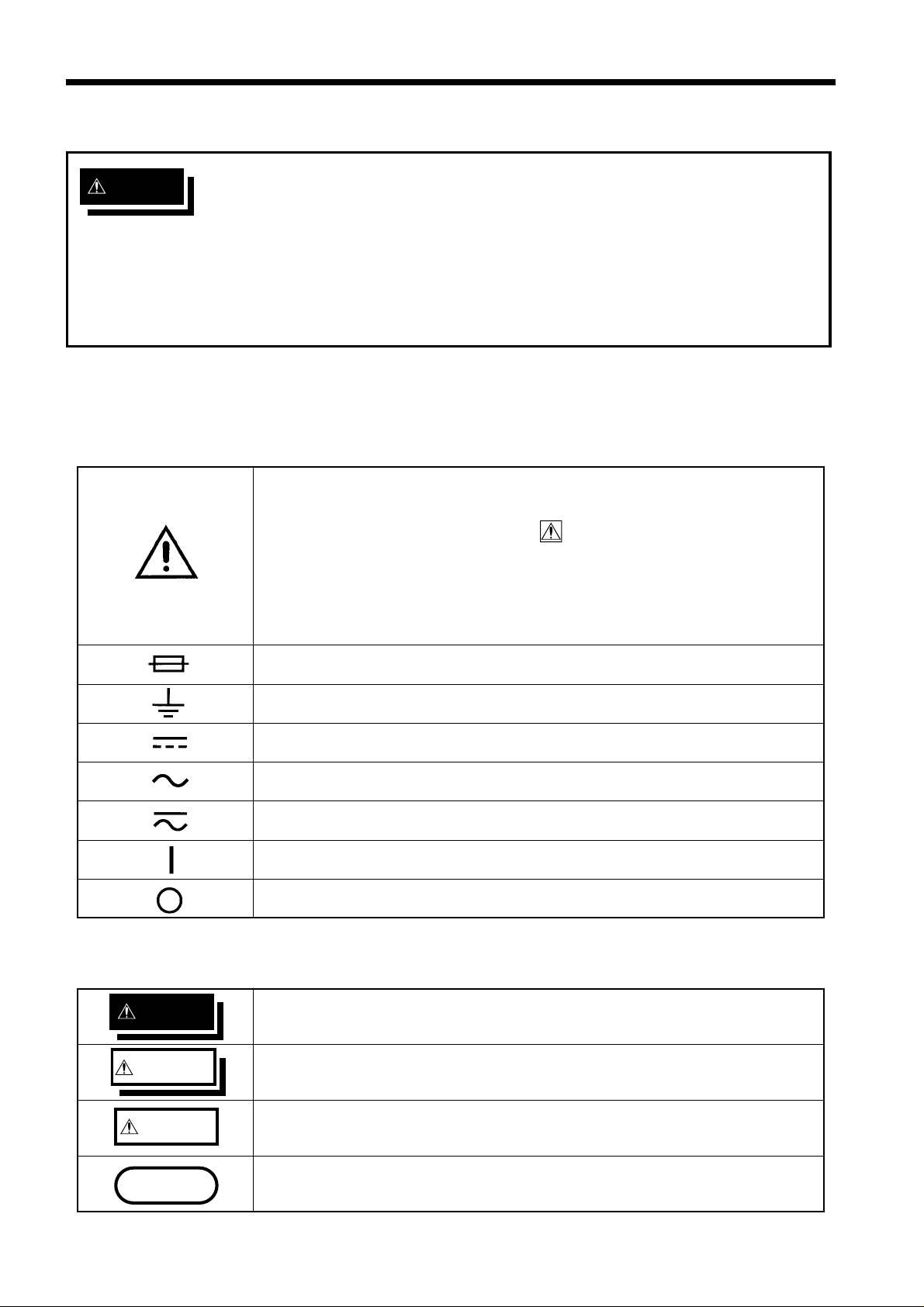
Safety symbols
・This symbol is affixed to locations on the equipment where the
operator should consult corresponding topics in this manual
(which are also marked with the
functions of the equipment.
・In the manual, this mark indicates explanations which it is
particularly important that the user read before using the
equipment.
symbol) before using relevant
Indicates a fuse.
Indicates a grounding terminal.
Indicates DC (Direct Current).
Indicates AC (Alternating Current).
Indicates both DC (Direct Current) and AC (Alternating Current).
Indicates the ON side of the power switch.
Indicates the OFF side of the power switch.
The following symbols are used in this Instruction Manual to indicate the relative importance
of cautions and warnings.
DANGE
WARNIN
Indicates that incorrect operation presents extreme danger of accident
resulting in death or serious injury to the user.
Indicates that incorrect operation presents significant danger of acciden
resulting in death or serious injury to the user.
CAUTIO
NOTE
────────────────────────────────────────────────────
Safety Notes
Indicates that incorrect operation presents possibility of injury to the
user or damage to the equipment.
Denotes items of advice related to performance of the equipment or to
its correct operation.
Page 15
iii
G
N
N
────────────────────────────────────────────────────
otes on Use
In order to ensure safe operation and to obtain maximum performance from
the unit, observe the cautions listed below.
Before measurement
WARNIN
Before turning on the power, make sure that the voltage of the power
supply being used matches the supply voltage indicated on the rear
panel of the unit. (3155: specified at order, 3155-01: set by the voltage
selector)
If an attempt is made to use an improper supply voltage, there is danger
of damage to this unit and of life-threatening risk to the operator.
The unit is constructed so as to be connected to a ground line via a
three-core power cord that is supplied with the unit. In order to avoid
electric shock, connect the unit to a properly grounded (3-pin) outlet
using the power cord provided.
Before using the unit, make sure that the sheathing on the leads /
probes is not damaged and that no bare wire is exposed. If there is
damage, using the unit could cause electric shock. Replace the lead /
probe with the specified 9195 or 9170, or optional 9461 or 9287.
To avoid the danger of electric shock, never operate the unit with a
measurement network removed.
Do not swithc the voltage selector when the power is turned on.
CAUTIO
NOTE
Do not press hard upon the touch screen, or operate it using a hard object or
one with a sharp end. Doing so could scratch or damage the screen or the
soft keys.
・Of the three optional Measurement Networks (9497, 9498 and 9499), one
must be installed with the 3155 or no measurements can be made. If the
power to the 3155 is turned on without having installed one of the networks,
the message ’Measurement Network not installed.’ will appear on the LCD.
In which case, please install a measurement network as described in Section
4.1, "Installing the Measurement Network."
・Because the current consumption monitor is AC coupled, errors occur when
measuring an AC current which includes a DC offset. (Example: half-wave
rectified current)
────────────────────────────────────────────────────
Notes on Use
Page 16

iv
N
G
────────────────────────────────────────────────────
Connection
CAUTIO
・In order to avoid electric shock, turn off the power to all devices before
plugging in or unplugging the measurement network or RS-232C connector.
・When unplugging the power cord from the power receptacle or from the unit,
grasp the plug, not the cord, in order to avoid damaging the cable.
・To avoid damaging the leads or probes, do not bend or pull the leads or
probes.
・Use caution when taking measurements in circuits where the power line are
hot.
・For safety reasons, only use the 9195 or 9170 probe / test lead provided with
the unit, or the optional 9461 or 9287 for measurement.
・The changing of the function when replacing the test terminals requires
disconnection of the test leads from the equipment being measured and then
the disconnection of the test leads from the terminals.
・To avoid damage to the unit, do not short the output terminal and do not
input voltage to the output terminal.
・Use the unit near the power receptacle.
During measurement
WARNIN
The 9196 APPLY UNIT used in the measurement of enclosure leakage
current, patient leakage current
and patient leakage current
continuously outputs voltage while the voltage application button is
being pressed. Care is required to avoid accidents caused by electrical
shock.
The leakage current measurement terminals, the resistance
measurement terminals and the RS-232C connector are not insulated.
Handle these items carefully in order to avoid electric shock or a short
circuit accident.
If the end of a lead or a probe short-circuits lines with a voltage between
them, this is very dangerous and can lead to a serious accident.
Exercise great care when measuring voltages.
In the event that the equipment malfunctions in any manner during use,
turn off the power immediately, and contact your dealer or HIOKI
representative.
────────────────────────────────────────────────────
Notes on Use
Page 17

v
Monitor lamps
R
N
G
────────────────────────────────────────────────────
Input
DANGE
NOTE
When the power to the 3155 is turned on, if the
MON2 and MON3 lamps are illuminated, an
accurate measurement can be obtained. (The unit
can also be wired so that MON1 and MON2
illuminate.)
For details, refer to Section 4.3, "Powering on and
off the Unit."
To avoid electric shock and damage to the unit, do not input a voltage
exceeding the permissible common mode voltage to the leakage current
measurement terminals. The permissible common mode voltage is 250 V
(DC+AC peak). (In the 50 μA range, 20 V (DC+AC peak))
CAUTIO
Replacement
WARNIN
When the power is turned off, do not apply voltage or current to the leakage
current measurement terminals or resistance measurement terminals. Doing
so may damage the unit.
Only use fuses of the specified type that is rated for the specified
current and voltage. Using a fuse that does not meet the specifications
or shorting the fuse holder may cause an accident that might result in
injury or death.
(120 V: 250 V T0.5 AL, 200/240 V: 250 V T0.25 AL 20 mm × 5 mm dia.
(3155))
(110 to 120/200/240 V: 250 V T0.2 AL 20 mm × 5 mm dia. (3155-01))
When replacing the fuse and measurement network, always power off
the unit.
────────────────────────────────────────────────────
Notes on Use
Page 18
vi
G
────────────────────────────────────────────────────
Operating environment
WARNIN
NOTE
To prevent electric shock, do not allow the unit to become wet and do
not use the unit when your hands are wet.
The interior of the 3155 contains some components which are subject to
high voltage, and therefore dangerous. Absolutely do not remove the
cover panel. In particular, be careful of the 9196 APPLY UNIT, which is
subject to high voltage.
To avoid damage to the unit, do not subject the equipment to vibrations
or shocks during transport or handling. Be especially careful to avoid
dropping the equipment.
The unit should always be operated indoors in a range from 5℃ to 40℃
and 35% to 80% rh. Do not use the unit in direct sunlight, dusty
conditions, or in the presence of corrosive gases.
Do not use the unit near any device which generates strong
electromagnetic radiation or near a static electrical charge, as these may
cause errors.
・Accurate measurement may be impossible in locations subject to strong
external magnetic fields, such as transformers and high-current conductors,
or in locations subject to strong external electric fields, such as radio
transmission equipment.
・Do not use the 3155 in operating rooms, ICUs, CCUs or other areas where
an isolated electrical supply is used. To do so will result in inaccurate
readings.
────────────────────────────────────────────────────
Notes on Use
Page 19

vii
────────────────────────────────────────────────────
Printer and recording paper
Printer
・Using the printer in a high-temperature or high-humidity environment
should be avoided at all costs. This can seriously reduce the printer life.
・Because the thermal printing head is subject to high temperatures during
printing, do not touch the head itself or its support sections either during or
directly after printing. Care is also necessary when replacing the paper or
during maintenance. For paper replacement, refer to Section 4.4, "Loading
Recording Paper."
・Because the motor is subject to high temperature during operation, do not
touch it either during or directly after printing.
・To prevent the motor from being overheated, do not press the feed switch
continuously for more than 3 minutes.
Recording paper
・This unit uses a thermal printer. The recording paper supplied has
characteristics finely tuned for use with the printer.
Using recording paper of a different specification may not only result in
impaired printing quality, but even prevent the printer from operating.
Always use the HIOKI specified product.
・If light reaches the paper over a long period, the paper will discolor. Do not
unwrap rolls of paper until you are ready to use them.
・The recording paper uses a thermochemical reaction. Note the following
points:
・To avoid discoloration, do not leave recording paper in direct sunlight.
Store at not more than 40℃ and 90% rh.
・To keep definitive data, make photocopies of the recordings.
・If the thermal paper absorbs an organic solvent such as alcohols or
ketones it may no longer develop properly, and recorded information may
fade. Soft PVC film and transparent contact adhesive tape contain such
solvents, so avoid using them with recordings.
・Avoid interleaving the thermal recordings with damp diazo copies.
────────────────────────────────────────────────────
Notes on Use
Page 20

viii
C
────────────────────────────────────────────────────
ontents of this Manual
The operating methods of the 3155 LEAK CURRENT HiTESTER will vary
depending upon the type of measurement network used. The various
operating methods for each type of measurement network are shown in
Chapters 5 to 7. Although there is some repetition between chapters, to
ensure safe operation please read thoroughly the chapter pertaining to the
measurement network you use.
Chapter 1: Overview
Gives an overview and features of the unit.
Chapter 2: Names of Functions of Parts
Describes the names and functions of the parts of the unit.
Chapter 3: Options
Describes the options (measurement networks and application
units) of the unit.
Chapter 4: Preparations for Measurement
Describes the installation and preparatory work.
Chapter 5: Medical Electrical Equipment Measurement
(9497 NETWORK B installed)
Describes the medical electrical equipment measurement.
Chapter 6: Ordinary Electrical Equipment Measurement (for IEC/TR 60990)
(9498 NETWORK C installed)
Describes the ordinary electrical equipment measurement (for
IEC/TR 60990).
Chapter 7: Ordinary Electrical Equipment Measurement (Universal)
(9499 NETWORK D installed)
Describes the ordinary electrical equipment measurement
(universal).
Chapter 8: Command Reference
Describes the RS-232C communications and their operation
examples.
Chapter 9: Specifications
Contains the unit specifications such as the general specifications,
measurement ranges, accuracy, etc. of the unit.
Chapter 10: Maintenance and Servicing
Covers the maintenance and servicing.
Appendices: Covers the error messages, leakage current measurement,
standards and glossary.
────────────────────────────────────────────────────
Contents of this Manual
Page 21

1
1
w
1
────────────────────────────────────────────────────
Chapter
1
2
.1 Product Introduction
The HIOKI 3155 LEAK CURRENT HiTESTER is a leakage current
measuring instrument for use in testing electrical equipment used in a wide
variety of applications from computers to medical care. Not only does it
conform to all standards for testing medical electrical equipment, but also to
laws and standards applicable to equipment for non-medical care as well.
By using one of three (optional) measurement networks that simulate the
human body, measurements that conform to a variety of laws and standards
for electrical equipment can be made.
Once the measurement network for the equipment to be measured is attached,
a measurement screen conforming to the applicable requirements is displayed.
By using the ’touch keys’ on the screen, measurements are easily made. (For
patient leakage current
current, the 9196 APPLY UNIT is necessary.)
To ensure safety in the use of electrical equipment, a wide variety of tests for
characteristics such as insulation resistance, earth resistance, leakage current,
etc., need be made. The 3155 is designed to be used in leakage current testing
in a variety of fields.
Overvie
, patient leakage current and enclosure leakage
3
4
5
6
7
8
9
10
11
12
13
14
A
────────────────────────────────────────────────────
1.1 Product Introduction
Page 22

2
1
────────────────────────────────────────────────────
Used by:
Manufacturers of medical electrical equipment For formal inspections and pre-shipping inspections
Sales agents of medical electrical equipment For inspection and maintenance
Personnel performing repairs on medical electrical
equipment
Clinical engineering technologists at hospital For inspection and maintenance
Clinical engineering technologists training schools For educational purposes
Electrical contractors qualified to install operating
rooms, ICUs and CCUs
Public agencies For formal inspections
Manufacturers of electrical equipment For formal and pre-shipping inspections
Users of electrical equipment For inspection and maintenance
Electrical contractors For inspection and maintenance
Electrical repair technicians For inspection and maintenance
Manufacturers of electrical components For formal and pre-shipping inspections
Manufacturers of electric generators For formal and pre-shipping inspections
For inspection and maintenance
For inspections of insulated transformers
.2 Features of the 3155
(1) Measurement networks that conform to a variety of laws and standards
In order to perform a variety of tests that conform to the various laws and
standards applicable to leakage current testing, it is necessary to utilize a
measurement network that simulates the human body when making
measurements. Different measurement networks conform to different laws
and standards:
9497 NETWORK B: IEC 60601-1
9498 NETWORK C: IEC/TR 60990
9499 NETWORK D: IEC 60065, IEC 60335-1, UL
These measurement networks can also be used to perform tests that conform
to a variety of other standards as well. For details, refer to Section 3.1,
"Measurement Networks."
(2) Superior operability
All operations are performed via the display screen touch panel. The
operational keys are displayed on the screen for interactive operation.
(3) Measuring mode
Once a measurement network has been attached to the back of the 3155 unit
and the power is turned on, the measuring modes available in that network
are displayed on the screen.
Earth leakge current Enclosure leakage current
Patient leakage current Patient leakage current
Patient leakage current Patient auxiliary current
Low resistance measurement
────────────────────────────────────────────────────
1.2 Features of the 3155
Page 23

3
────────────────────────────────────────────────────
(4) Leakage current measurement
The user can select a measuring mode from the ones available in the
measurement network. The configuration of the instrument will also effect
which modes are available. The necessary modes are displayed from
(5) Low resistance measurement
Low resistance measurement of a protective earth conductor is performed at a
current of 25 AAC or DC as prescribed in all standards. The 3155 is equipped
with a DC 4-terminal method measurement (at 100 mADC max.) function for
easy measurement. Measurement is also possible using RS-232C interfacing
with the 3157 AC GROUNDING HiTESTER (max. 31A AC, conforming to
various standards), available separately.
(6) Interface
An RS-232C interface is standard equipment to allow for easy transfer of
measurement data to a computer.
(7) Built-in printer
The built-in thermal serial printer allows for easy printout of saved data.
(8) Monitor function
Equipped with a line voltage and current consumption monitor.
(9) Voltage selector (3155-01 only)
The equipment with the power voltages of 110 to 240 V can be measured with
a single unit.
to .
1
2
3
4
5
6
7
8
9
10
11
12
13
14
A
────────────────────────────────────────────────────
1.2 Features of the 3155
Page 24

4
s
t
g
h
t
d
t
r
t
t
t
t)
1
────────────────────────────────────────────────────
.3 Measuring Mode of the 3155
The 3155 has been designed with the idea in mind that leakage current
testing is the most important of all tests for electrical safety. In particular, for
medical electrical equipment, leakage current has the greatest potential for
harming human beings, and is therefore strictly regulated even with regard to
single fault conditions. Through the use of measurement networks B, C and
D, the 3155 can perform leakage current testing for all types of electrical
equipment from ordinary electrical equipment to medical electrical equipment.
For details, refer to Section 3.1, "Measurement Networks."
NOTE
Measurement network type
9497 NETWORK B
9498 NETWORK C
9499 NETWORK D
Earth leakage current Enclosure leakage current
Patient leakage current Patient leakage current
Patient leakage current Patient auxiliary current
Low resistance measurement
Earth leakage current Enclosure leakage current
Low resistance measurement
Earth leakage current Enclosure leakage current
Low resistance measurement
Setting for normal condition or single fault conditions is possible. The polarity
Available measuring modes
of the power source can also be set.
The voltage input from the power inlet is directly output to the auxiliary
outlet for the equipment to be measured.
When testing with the 110% power voltage, input it to the power inlet.
Leakage current route of the medical electrical equipment (ME equipmen
Faulty ME equipmen
Faulty ME equipmen
Signal input an
Medical outle
Eart
output parts
3-P plu
Protective earth conducto
Earth leakage curren
Enclosure leakage curren
ME equipmen
Patient leakage current
Patient leakage current
Patient leakage current
For details, refer to Appendix 2, "Leakage Current Measurement."
────────────────────────────────────────────────────
1.3 Measuring Mode of the 3155
Page 25

5
)
)
)
)
n
n
e
e
e
r
y
d
n
n
h
n
n
n
n
e
e
e
n
e
e
r
y
1
────────────────────────────────────────────────────
.4 Leakage Measurement Types
1
2
Earth leakage current
(ordinary electrical equipment or
medical electrical equipment)
A current between the protective eart
terminal and the earth is measured.
Enclosure leakage current
(ordinary electrical equipment or
medical electrical equipment)
Currents between the enclosure an
the earth, and between parts of the
enclosure are measured.
Patient leakage current
(medical electrical equipment
A current is measured betwee
the applied and the earth.
Normal condition
Single fault condition
Normal conditio
Single fault condition
Normal conditio
Single fault conditio
Interruption of on
supply conductor
Interruption of on
supply conductor
Interruption of a protectiv
earth conductor
A voltage equivalent to 110% of
the maximum rated voltage is
applied between the signal input o
output part which is not protectivel
earthed and the earth
(medical electrical equipment only)
Interruption of on
supply conductor
Interruption of a protectiv
earth conductor
3
4
5
6
7
8
Patient leakage current
(medical electrical equipment
A current is measured betwee
the applied part and the earth.
Patient leakage current
(medical electrical equipment
A current is measured betwee
the F-type applied part and the
faulty equipment.
Patient auxiliary current
(medical electrical equipment
A current is measured betwee
parts of the applied part.
NOTE
・Measurements including the combined single fault conditions is not possible.
・The optional 9196 APPLY UNIT is required to apply a voltage equivalent to
110% of the maximum rated voltage.
Single fault condition
Single fault condition
Normal conditio
Single fault conditio
A voltage equivalent to 110% of
the maximum rated voltage is
applied between the signal input o
output part which is not protectivel
earthed and the earth
(medical electrical equipment only)
A voltage equivalent to 110%
of the maximum rated voltag
is applied between the F-type
applied part and the earth.
Interruption of on
supply conductor
Interruption of a protectiv
earth conductor
9
10
11
12
13
14
A
────────────────────────────────────────────────────
1.4 Leakage Measurement Types
Page 26
6
s
t
t
)
t
)
)
1
────────────────────────────────────────────────────
.5 Standards Regarding Leakage Current
The measurement network you use will vary depending upon the standards to
which you must conform.
There are instances where testing for leakage current is required by standard
to be included in formal testing, or in ownership transfer testing as well.
Standard
NOTE
Medical electrical equipmen
Electrical measuring instrumen
Electrical equipmen
The standards above are subject to amendment. For details, refer to each
standard.
IEC 60950 (1991-10) + am4 (1996-07),
IEC/TR 60990 (1990-06),
IEC 60065 (1998-07),
IEC 60335-1 (1991-06) + am1 (1994-11
IEC 60601-1 (1988-12) + am1 (1991-11
+ am2 (1995-03)
IEC 61010-1 (1990-09) + am1 (1992-09
+ am2 (1995-07)
────────────────────────────────────────────────────
1.5 Standards Regarding Leakage Current
Page 27

7
2
of
ts
────────────────────────────────────────────────────
Chapter
1
2
Names and Functions
Par
3
4
5
6
7
8
9
10
11
12
13
14
A
────────────────────────────────────────────────────
Page 28
8
Enlarged diagram of the terminal section
3
3
────────────────────────────────────────────────────
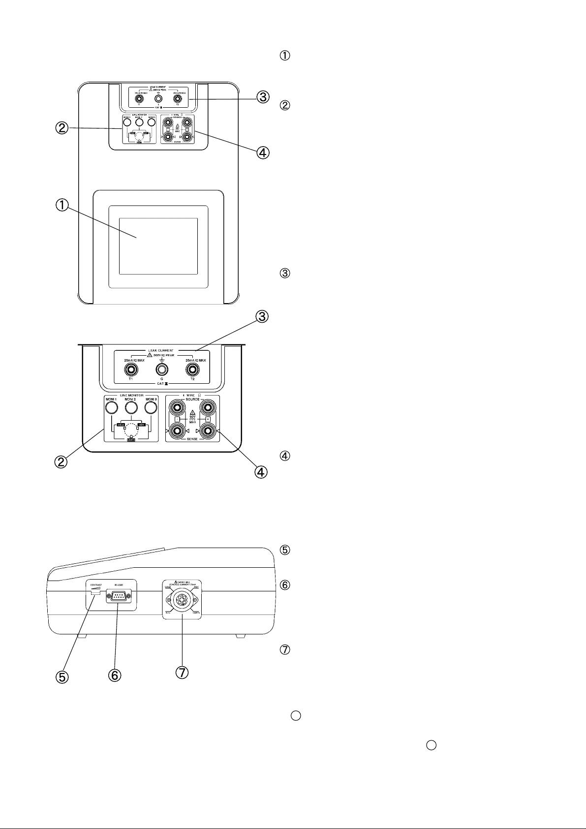
Top view
Liquid crystal display
This 5-inch display includes a touch panel
which performs the role of the input keys.
Monitor lamps
The condition of elements such as the power
line ground are indicated by these monitor
lamps.
When the power to the 3155 is turned on, if
the MON2 and MON3 lamps are illuminated,
an accurate measurement can be obtained.
(The unit can also be wired so that MON1 and
MON2 illuminate.)
For details, refer to Section 4.3, " Powering on
and off the Unit."
Leakage current measurement terminals
There are three terminals available.
G: G terminal (connects to the earth terminal
of the equipment to be measured)
T1: Leakage current measurement terminal T1
(Location of connection to the equipment
to be measured varies with the measuring
mode.)
T2: Leakage current measurement terminal T2
(Location of connection to the equipment
to be measured varies with the measuring
mode.)
Right side view
Resistance measurement terminals
There are four terminals available.
SOURCE(+), SENSE(+), SENSE(-), SOURCE(-)
The SOURCE banana plug of the 9461 or 9287
is to be connected to SOURCE, and the
SENSE to SENSE.
Contrast adjustment knob
Use this knob to adjust the screen contrast.
RS-232C connector (Dsub 9 pin male)
Connect a RS-232C cable here to communicate
with an external controller such as a
computer.
Auxiliary power socket (for the equipment to be
measured)
(earthed 3-pin socket - 1500 VA max.)
Plug the equipment to be measured in here.
Outputs the voltage input from the power inlet
1
directly.
When testing with the 110% power voltage,
input it to the power inlet
1
.
Use the supplied power plug for connection.
────────────────────────────────────────────────────
Page 29

9
101312
11
3155
101413
11
3155-01
Voltage selector key
1
2
3
4
────────────────────────────────────────────────────
Left side view
Front view
Internal printer
Prints out the measurement results etc.
Handle
This is used for transporting the 3155.
1
2
3
4
5
6
Rear view
Main power switch
Powers the 3155 on(|)or off(○).
(With the 3155-01, includes the function of the
auxiliary power outlet circuit breaker.)
1
Fuse holder
Insert the proper fuse here, as indicated on
the label.
1
Auxiliary power outlet circuit breaker (3155 only)
In the event that the current to the auxiliary
power outlet
will trip.
ON(|): Current is being supplied to the
auxiliary power outlet.
OFF(○): Current is not being supplied to
the auxiliary power outlet.
1
Power inlet
Connect the grounded three-core power cord
supplied here.
exceeds 1500 VA, this breaker
7
8
9
10
11
12
13
────────────────────────────────────────────────────
1
Voltage selector key (3155-01 only)
Insert the supplied voltage selector key into
the keyhole of the voltage selector, and select
the power voltage by setting it to the required
power voltage.
For details, refer to Section 4.2, " Power Cord
Connection."
14
A
Page 30

10
15
5
────────────────────────────────────────────────────
Auxiliary power outlet circuit breaker
The unit uses the medium-speed breaker for the rush current of the
equipment to be measured.
Refer to the following table for breaking characteristics.
Bottom view
1
Measurement network socket
Use this socket to attach the measurement
network that conforms to your needs.
The following measurement networks are
available:
a. 9497 NETWORK B: Medical electrical
equipment
b. 9498 NETWORK C: IEC/TR 60990
c. 9499 NETWORK D: IEC 60065, IEC 60335-1,
UL
NOTE
For measurement networks, refer to Section 3.1,
"Measurement Networks," and for installation,
Section 4.1, "Installing the Measurement
Network."
────────────────────────────────────────────────────
Page 31

11
161718
19
r
To the auxiliary
power socket
Changing the power
source polarity
interruption of a protective
earth conductor
interruption of one
supply conductor
From the power
inlet
H (L)
C (N)
GGC (N)
H (L)
6
7
8
9
────────────────────────────────────────────────────
Interior of the built-in printe
Inside the changeover box
A changeover box is built into the 3155.
It is built between the power inlet and the auxiliary power socket.
It outputs changing the power source polarity and the condition. So the power
source polarity (normal or reverse polarity) can be changed easily, and the
single fault condition (interruption of one supply conductor or interruption of a
protective earth conductor) can be set easily.
1
Printer cover
1
Recording paper holder
1
Paper feed
1
Feed switch
1
2
3
4
5
6
7
8
9
10
11
12
13
14
A
────────────────────────────────────────────────────
Page 32

12
Outlet
T1T2G
Auxiliary power outlet
Measurement
network
Protective earth
terminal
3155
Outlet
T1T2G
Auxiliary power outlet
Measurement
network
Protective earth
terminal
3155
Outlet
T1
T2
G
Auxiliary power outlet
Measurement
network
Protective earth
terminal
3155
────────────────────────────────────────────────────
Connections of G, T1 and T2
(1) In the earth leakage current measurement mode
G and the earth electrode of the auxiliary power outlet are connected to one
side of the measurement network.
The other side of the measurement network is connected through the
protective earth terminal and its conductor to the ground.
(2) In the enclosure leakage current mode (contact condition: between the enclosure
and the earth) and patient leakage current
measurement modes
T2 is connected to one side of the measurement network.
The other side of the measurement network is connected through the
protective earth terminal and its conductor to the ground.
(Class , equipment) and
G and the earth electrode of the auxiliary power outlet are connected through
the protective earth terminal and its conductor to the ground.
(3) In the enclosure leakage current mode (contact condition: between parts of the
enclosure (when the 9497 is installed) and between the enclosure and the power
line (when the 9498 or 9499 is installed)), patient leakage current
(Internally
powered equipment) measurement modes, patient leakage current
measurement mode and patient auxiliary current measurement modes
T2 is connected to one side of the measurement network.
T1 is connected to the other side of the measurement network.
G and the earth electrode of the auxiliary power outlet are connected through
the protective earth terminal and its conductor to the ground.
────────────────────────────────────────────────────
Page 33

13
3
V
1
0.1%
10 kΩ±0.1%
0.015 μF
1%
V
s
d
3
s
3
────────────────────────────────────────────────────
Chapter
1
2
.1 Measurement Networks
Please choose one of the three measurement networks that simulate the
human body to perform measurements conforming to standards for electrical
equipment to be tested.
The measurement networks cannot be used separately, but must always be
installed on the 3155.
For the installation procedure, refer to Section 4.1, "Installing the
Measurement Network," and for the fuse replacement, Section 10.2.2,
"Replacement of the Measurement Network Fuse."
Option
3
4
5
6
7
8
.1.1 9497 NETWORK B (for the Medical Electrical Equipment)
This measurement network is for the medical electrical equipment.
Measurement network B conforms to the following standard:
Medical electrical equipment Part 1: General requirements of safety (IEC
60601-1 (1988-12) + am1 (1991-11) + am2 (1995-03))
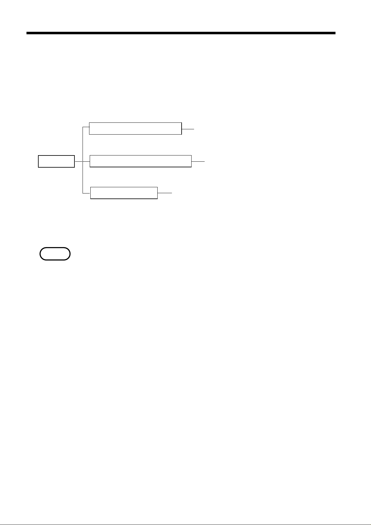
By installing on the 3155 and making the appropriate settings from the
screen, a configuration with a network with frequency characteristics for ON,
and a network with only 1 kΩ of uninduced resistance for OFF is established.
kΩ
±
±
1kΩ±0.1%
Network with frequency characteristic
(ON)
Network with only 1 kΩ of uninduce
resistance (OFF)
9
10
11
12
13
14
A
────────────────────────────────────────────────────
3.1 Measurement Networks
Page 34

14
3
V
1.5 kΩ
0.1%
0.22 μF
1%
500 Ω
0.1%
0.0062μF
1%
20 kΩ
0.1%
0.0091μF
1%
10kΩ±0.1%
V
V
0.022μF
1%
0
μF
1%
1
Ω
0.1%
500 Ω
0.1%
1.5 kΩ
0.1%
0.22 μF
1%
500 Ω
0.1%
10 kΩ±0.1%
)
)
)
────────────────────────────────────────────────────
Specifications
Standard Medical electrical equipment Part 1: General requirements ofsafety (IEC 60601-1
(1988-12) + am1 (1991-11) + am2 (1995-03))
Measuring circuit
Basic measuring element 1 kΩ, frequency characteristics ±0.5% (DC to 1 MHz)
configuration
Low pass filter function (1MΩ load with input protection fuse shorted)
Filter configuration (ON setting): RC filter (10 kΩ+15 nF)
Cutoff frequency, fc (at -3 dB): 1061 Hz±16 Hz
Passband attenuation: 0 dB±2% (at 100 Hz)
Attenuation: -20 log (f/fc) ±1dB (10 kHz≦f≦1 MHz)
Filter setting: On/off switch (off: 1 kΩ only)
Approved tolerances
±0.1% for resistance, ±1% for capacitor
for element
Fuse 250 V T0.032 AL 20 mm×5 mm dia.
Dimensions and mass 140W × 35H × 29D mm(5.51"W × 1.38"H × 1.14"D), approx. 70 g(2.5 oz.)
Accessories Instruction Manual, spare fuse
.1.2 9498 NETWORK C (for IEC/TR 60990)
This measurement network conforms to IEC/TR 60990.
Measurement network C conforms to the following standard:
Methods of measurement of touch-current and protective conductor current
(IEC/TR 60990 (1990-06))
By installing on the 3155 and making the appropriate settings from the
screen, a configuration with a body impedance network for OFF, a perception
and reaction network for ON1, and a let-go network for ON2 is established.
.5 k
±
.22
±
±
Body impedance network (OFF
±
±
±
±
±
±
Let-go network (ON2
±
±
±
±
Perception and reaction network (ON1
────────────────────────────────────────────────────
3.1 Measurement Networks
Page 35

15
────────────────────────────────────────────────────
Installation of measurement network C will enable leakage current testing
that conforms to the following standards:
・Safety requirements for electrical equipment for measurement, control, and
laboratory use Part 1: General requirements (IEC 61010-1 (1990-09) + am1
(1992-09) + am2 (1995-07))
・Safety of information technology equipment (IEC 60950 (1991-10) + am4
(1996-07))
・Audio, video and similar electronic apparatus - Safety requirements (IEC
60065 (1998-07))
・Applicable UL standards:(Examples:UL1419, UL3101-1, UL3111-1, etc.)
Specifications
Standard Methods of measurement of touch-current and protective conductor current
(IEC/TR 60990 (1990-06))
Measuring circuit
configuration
Filter configuration and
characteristics
Basic measuring element 1.5 kΩ+500 Ω
(1MΩ load with input protection fuse shorted)
OFF setting: High pass filter
Cutoff frequency (at -3 dB): 1805 Hz±27 Hz
Passband attenuation: 0 dB±2% (at 100 kHz)
Low-frequency attenuation: -12 dB±0.3 dB (at 100 Hz)
ON1 setting: (perception) 10 kΩ+22 nF
Passband attenuation: -12 dB±0.3 dB (at 100 Hz)
High-frequency attenuation: -42.8 dB±1 dB (at 100 kHz)
ON2 setting: (let-go) 10 kΩ+(20 kΩ+6.2 nF)//9.1 nF
Passband attenuation: -12 dB±0.3 dB (at 100 Hz)
High-frequency attenuation: -35.1 dB±1 dB (at 100 kHz)
1
2
3
4
5
6
7
8
Approved tolerances
for element
Fuse 250 V T0.032 AL 20 mm×5 mm dia.
Dimensions and mass 140W × 35 H × 29D mm(5.51"W × 1.38"H × 1.14"D), approx. 90 g(3.2 oz.)
Accessories Instruction Manual, spare fuse
±0.1% for resistance, ±1% for capacitor
9
10
11
12
13
14
────────────────────────────────────────────────────
3.1 Measurement Networks
A
Page 36

16
3
V
1. kΩ
0.1%
V
0.15 μF
2%
1.5 kΩ
0.1%
V
2kΩ
0.1%
Network of 2 kΩ (2 kΩ)
Network of 1 kΩ (1 kΩ)
Network of 1.5 kΩ and 0.15 μF (1.5 kΩ)
────────────────────────────────────────────────────
.1.3 9499 NETWORK D (Universal)
This is a universal measurement network.
Measurement network D conforms to the following standards:
Safety of household and similar electrical appliances - Part 1: General
requirements (IEC 60335-1 (1991-06) + am1 (1994-11))
Applicable UL standards:
By installing on the 3155 and making the appropriate settings from the
screen, a configuration with a network of 1 kΩ for 1 kΩ, a network of 1.5 kΩ
and 0.15 μF for 1.5 kΩ, and a network of 2 kΩ for 2 kΩ is established.
±
±
±
±
In addition, there are many applicable standards.
Specifications
Standard Safety of household and similar electrical appliances - Part 1:
General requirements (IEC 60335-1 (1991-06) + am1 (1994-11))
Applicable UL standards: (Examples: UL471, UL1310, UL1437, UL1492, etc.)
Measuring circuit
configuration/accuracy
Filter configuration and
characteristics
Approved tolerances
for element
Fuse 250 V T0.032 AL 20 mm×5 mm dia.
Dimensions and mass 140W × 35 H × 29D mm(5.51"W × 1.38"H × 1.14"D), approx. 80 g(2.8 oz.)
Accessories Instruction Manual, spare fuse
(a) Network of 1 kΩ
Impedance: 1 kΩ±0.5% (DC to 1 MHz)
(b) Network of 1.5 kΩ and 0.15 μF
Impedance: Theoretical value±0.5% (DC≦f≦400 Hz)
Theoretical value±(2%+1Ω) (400 Hz<f≦1 MHz)
Cutoff frequency (at -3 dB): 707 Hz±15 Hz
(c) Network of 2 kΩ
Impedance: 2 kΩ±0.5% (DC to 1 MHz)
(1MΩ load with input protection fuse shorted)
OFF setting: High pass filter
Cutoff frequency (at -3 dB): 1805 Hz±27 Hz
Passband attenuation: 0 dB±2% (at 100 kHz)
Low-frequency attenuation: -12 dB±0.3 dB (at 100 Hz)
ON1 setting: (perception) 10 kΩ+22 nF
Passband attenuation: -12 dB±0.3 dB (at 100 Hz)
High-frequency attenuation: -42.8 dB±1 dB (at 100 kHz)
ON2 setting: (let-go) 10 kΩ+(20 kΩ+6.2 nF)//9.1 nF
Passband attenuation: -12 dB±0.3 dB (at 100 Hz)
High-frequency attenuation: -35.1 dB±1 dB (at 100 kHz)
±0.1% for resistance, ±2% for capacitor
────────────────────────────────────────────────────
3.1 Measurement Networks
Page 37

17
T
)
────────────────────────────────────────────────────
ypical frequency response graphs of measurement networks
9497 NETWORK B
9498 NETWORK C
1
2
3
4
5
6
7
9499 NETWORK D
Impedance vs input frequency (1.5 kΩ//0.15 μF
8
9
10
11
12
13
────────────────────────────────────────────────────
3.1 Measurement Networks
14
A
Page 38

18
3
3
────────────────────────────────────────────────────
.2 9196 APPLY UNIT
.2.1 9196 APPLY UNIT
The 9196 APPLY UNIT is an instrument which outputs 110% of the input
power voltage.
Also, it has a function to break the circuit to prevent damage to the equipment
to be measured and electric shock to the user if an output current exceeding
6 mA.
Combined with the 3155 LEAK CURRENT HiTESTER, it is used to test
leakage current in medical electrical equipment. Leakage current from
medical electrical equipment has the greatest potential for harming human
beings, and is therefore strictly regulated even with regard to single fault
conditions. The following 6 types of testing for leakage current in medical
electrical equipment are available.
Earth leakage current Enclosure leakage current
Patient leakage current Patient leakage current
Patient leakage current Patient auxiliary current
The 9196 is used in testing for types
, , and .
NOTE
For the fuse replacement, refer to Section 10.2.3, "Replacement of the 9196
APPLY UNIT Power Source Fuse."
────────────────────────────────────────────────────
3.2 9196 APPLY UNIT
Page 39

19
3
────────────────────────────────────────────────────
.2.2 Names and Functions of the Parts of the 9196 APPLY
UNIT
Front view
1
2
3
4
5
6
Main power switch (POWER)
Powers the 9196 on and off.
Main power monitor (POWER MONI): Clear monitor lamp
The status of the main power is shown by this monitor lamp.
If illuminated, the power is ON.
If not illuminated, the power is OFF.
Polarity toggle switch (POLARITY)
This switch is used to toggle the polarity of the voltage output from the
voltage application probe. (in respect to the voltage input from the power inlet)
NORMAL: Polarity conforms with that of the voltage input from the power
inlet.
REVERSE: Polarity does not conform with that of the voltage input from the
power inlet.
Type toggle switch (TYPE)
Changes per the type of applied part of the equipment to be measured to
which voltage is applied.
B/BF: No protective resistance connected to the output point of the voltage
application probe.
CF: Protective resistance (10 kΩ) connected to the output point of the voltage
application probe in series.
Main power switch indication: |:ON ○: OFF
7
8
9
10
11
12
13
14
NOTE
────────────────────────────────────────────────────
When the type toggle switch of the 9196 APPLY UNIT is set to CF, there is a
10 kΩ protective resistance connected to the output point of the voltage
application probe in series. If the leakage current is large, the current flowing
from the output point will be subject to a reduction in voltage due to the
protective resistance, thereby reducing the actual output voltage.
3.2 9196 APPLY UNIT
A
Page 40

20
n
────────────────────────────────────────────────────
Voltage application probe connection terminal (OUTPUT)
Connect the 9190 VOLTAGE APPLY PROBE.
Output monitor (OUTPUT MONI): Red monitor lamp
The condition of the output to the voltage application probe is shown by this
monitor lamp.
If illuminated, the output is ON. (The voltage application button to the voltage
application probe is being held down.)
If not illuminated, the output is OFF.
Handle
Rear view
Fuse
Use the HIOKI specified fuse. (250 V T0.25 AL 20 mm×5 mm dia.)
Power inlet
The rated power voltage of the 9196 is 100 to 240 VAC (45 to 400 Hz), and the
maximum rated power is 25 VA.
Connect a grounded three-core power cord that is supplied with the unit.
Function earth terminal
If the protective ground terminal cannot be connected to the ground via a
grounded three-core power cord supplied, connect the function earth terminal
to the ground.
9190 VOLTAGE APPLY PROBE
Voltage application butto
────────────────────────────────────────────────────
3.2 9196 APPLY UNIT
Page 41

21
3
G
N
────────────────────────────────────────────────────
.2.3 9196 APPLY UNIT Operation
WARNIN
Before turning on the power, make sure that the voltage of the power
supply being used matches the supply voltage indicated on the rear
panel of the unit. (100 to 240 VAC)
The unit has no protective ground terminal, and is connected to a
ground line via a three-core power cord that is supplied with the unit.
In order to prevent electric shock, always connect the unit to a properly
grounded power outlet using the power cord provided.
The voltage application probe continuously outputs voltage while the
voltage application button is being pressed. While it is outputting, or
any time that the voltage application button is being pressed
intentionally, a dangerous amount voltage is present is at the tip of the
probe. To avoid electrical shock, do not touch either the device under
test or the probe tip.
Before using the unit, make sure that the sheathing on the probes is not
damaged and that no bare wire is exposed. If there is damage, using
the unit could cause electric shock. Replace the probe with the
specified 9190.
To prevent electric shock, do not allow the unit to become wet and do
not use the unit when your hands are wet.
CAUTIO
NOTE
・To avoid damaging the probes, do not bend or pull the probes.
・Do not store or use the unit where it will be exposed to direct sunlight, high
temperatures, high humidity, or condensation. If exposed to such conditions,
the unit may be damaged, the insulation may deteriorate, and the unit may
no longer satisfy its specifications.
・When unplugging the power cord from the power receptacle or from the unit,
grasp the plug, not the cord, in order to avoid damaging the cable.
・Use the unit near the power outlet.
・The 9196 is only able to operate to its full capability after it has been
properly grounded. Always use the power cord (grounded three-core power
cord) that is supplied with the unit to ground the unit.
・If operating the voltage application button to the 9190 VOLTAGE APPLY
PROBE quickly, the main power of the 9196 may be turned off.
(1) Be sure that the main power switch is turned to OFF.
(2) Being sure that the power source is of the correct voltage, connect the
grounded three-core power cord provided to the power inlet on the back of the
9196.
────────────────────────────────────────────────────
3.2 9196 APPLY UNIT
Page 42

22
────────────────────────────────────────────────────
(3) Insert the plug into the outlet. The cord is automatically grounded.
(4) Attach the 9190 VOLTAGE APPLY PROBE.
Attach the 9190 VOLTAGE APPLY PROBE provided to the connecting
terminal on the front of the 9196.
(5) Turning the power on and off.
1. Turning the power on
Set the main power switch on the front of the unit to ON.
Verify that the main power monitor lamp is illuminated when the switch is set
to ON.
2. Turning the power off
Set the main power switch on the front of the unit to OFF.
(6) Applying voltage
1. Make the appropriate settings based on the type and voltage polarity of the
equipment to be measured.
Set the type based on the type of applied part of the equipment to be
measured.
B/BF: No protective resistance connected to the output point of the voltage
application probe.
CF: Protective resistance (10 kΩ) connected to the output point of the voltage
application probe in series.
Set the voltage polarity.
NORMAL: Polarity conforms with that of the voltage input from the power
inlet.
REVERSE: Polarity does not conform with that of the voltage input from the
power inlet.
2. Apply the voltage
If the 3155 LEAK CURRENT Hi TESTER and the equipment to be measured
are ready, touch the tip of the 9190 VOLTAGE APPLY PROBE to the contact
point. After verifying that there is no danger of electrical shock, press the
voltage application button to the 9190 VOLTAGE APPLY PROBE with your
finger. If the red output monitor lamp is illuminated while pressing the
voltage application button, the voltage is being output.
3. Cease application of voltage
Release your finger from the voltage application button.
────────────────────────────────────────────────────
3.2 9196 APPLY UNIT
Page 43

23
3
────────────────────────────────────────────────────
.2.4 9196 APPLY UNIT Specifications
General specifications
Output function Alternating current (AC V)
Output indication Red monitor lamp
Power indication Clear monitor lamp
Type toggle Toggle switch (B/BF, CF)
Polarity toggle Toggle switch (NORMAL /REVERSE)
Output configuration Voltage application probe (9190) connector receptacle
Additional functions Output control function (power cutoff)
Output only when the voltage application button to the 9190 is being pressed.
Dimensions 125W × 75H × 230D mm(4.92"W × 2.95"H × 9.06"D) (excluding projections)
Mass Approx. 2.5 kg(88.2 oz.) (excluding accessories)
Accessories Grounded three-core power cord
Instruction Manual
9190 VOLTAGE APPLY PROBE
Fuse 250 V T0.25 AL 20 mm × 5 mm dia.
Electric characteristics
Rated power voltage 100 to 240 VAC
(Voltage fluctuations of 10% from the rated supply voltage are taken into account.)
Rated power frequency45 to 400 Hz
Maximum rated power 25 VA
Insulation resistance 500 VDC, 100 MΩ min. between power supply and frame
Dielectric strength 2.3 kVAC sin (50/60 Hz), 1 minute between power supply and frame
Output breaking
current
Output voltage 110% voltage of the input supply voltage (VAC)
Accuracy ±(1.0% rdg.+1 V)
6 mAAC typical
B/BF range: In a load current of 5 mA or less
CF range: In a load current of 50 μA or less
Environmental conditions
Operating temperature
and humidity range
Storage temperature
and humidity range
5to40℃(40 to 104。F), 35 to 95% rh (no condensation)
-10 to 50℃(14 to 122。F), 35 to 95% rh (no condensation)
Accuracy assurance 23±5℃(73±41。F), 35 to 80% rh (no condensation)
Operating place Indoors, max. 2000 m(6562 feet) height
Standards applying EMC EN55011:1991
EN50082-1:1992
EN61000-3-2:1995
EN61000-3-3:1995
Safety EN61010-1:1993+A.2:1995 Pollution Degree 2,
Overvoltage Category (anticipated transient overvoltage 2500 V)
────────────────────────────────────────────────────
3.2 9196 APPLY UNIT
Page 44

24
Velcro tape
9399 CARRYING CASE
(for accessories)
9196 APPLY UNIT and accessories
such as the power cord
Instruction manual
3
────────────────────────────────────────────────────
.3 9388 CARRYING CASE (with Casters)
The 9388 CARRYING CASE (with casters) is made for storage and transport
of the 3155. In addition to the 3155, it accommodates accessories, including
the optional 9196 APPLY UNIT
Storage of the 3155
In the carrying case, the 3155 is immobilized with Velcro tape.
Accessories such as the power cord and optional 9196 APPLY UNIT are
housed in a covered case.
If necessary, cushioning material may be added to the case to provide extra
protection.
When storing the 9399 CARRYING CASE (for accessories), position it so that
the end with the metal fixtures is oriented toward the top cover of the case.
Manuals and other documents can be stored in the top cover.
────────────────────────────────────────────────────
3.3 9388 CARRYING CASE (with Casters)
Page 45

25
4
r
nt
────────────────────────────────────────────────────
Chapter
1
2
Preparations fo
Measureme
3
4
5
6
7
8
9
10
11
12
13
14
A
────────────────────────────────────────────────────
Page 46

26
k
t
s
4
────────────────────────────────────────────────────
.1 Installing the Measurement Network
(1) Be sure that both the 3155 and the equipment to be measured are powered off.
Be sure that the power cord, probe, leads etc. are not connected to the 3155.
(2) Attach one of the three optional measurement networks (9497, 9498 and
9499). Hold the measurement network by the two knobs, and insert into the
slotted connector on the 3155. After inserting firmly in place, attach the two
screws.
NOTE
・After turning on the power, a measurement network is checked.
1. In the event that a measurement network is not installed, or has not been
installed properly, the message ’Measurement Network not installed.’ will
appear on the liquid crystal display screen.
2. In the event that a fuse of a measurement network is not installed, or is
blown, the message ’Measurement Network Fuse blown.’ will appear on
the liquid crystal display screen.
This message may also appear when the signal is being input to the
leakage current measurement terminal T1. Check with nothing
connected to the leakage current measurement terminal T1.
For the fuse replacement, refer to Section, 10.2.2, "Replacement of the
Measurement Network Fuse."
・The type of measurement network currently installed on the 3155 can be
verified by opening the ’Measurement Network Filter Set-up Window,’
where one of the following messages is displayed:
9497 NETWORK B: Measurement network filter for ME
9498 NETWORK C: Measurement network filter for IEC 60990
9499 NETWORK D: Universal measurement network filter
Knob
Slo
────────────────────────────────────────────────────
4.1 Installing the Measurement Network
Measurement networ
Page 47

27
G
N
t
)
4
────────────────────────────────────────────────────
.2 Power Cord Connection
1
2
WARNIN
CAUTIO
Versions of the 3155 that operate on 120 V, 200 V and 240 V of the
supply voltage are available. The 3155-01 operates on 110 to 120 V, 200
V and 240 V with the voltage selector.
Before turning on the power, make sure that the voltage of the power
supply being used matches the supply voltage indicated on the rear
panel of the unit. The maximum rated power of the 3155 is 30 VA.
The protective ground terminal of the unit is connected to a ground line
via a three-core power cord that is supplied with the unit.
In order to prevent electric shock, always connect the unit to a properly
grounded power outlet using the power cord provided.
・To prevent an error, always remove the key and keep it after setting the
power supply voltage. (3155-01 only)
・When changing the supply voltage, always turn off the power and disconnect
the power cord before beginning. (3155-01 only)
・This unit is provided with a grounded three-core power cord that is suitable
for use with power supply conditions in the country or region in which the uni
is sold. When using this unit in any other country or region, be sure to
obtain a grounded three-core power cord which is suitable for use with the
power supply conditions in that area.
3
4
5
6
7
8
NOTE
The 3155 is a leakage current measuring instrument, and thererfore is only
able to operate to its full capability after it has been properly grounded.
Always use the power cord (grounded three-core power cord) that is supplied
with the unit to ground the unit.
(1) Be sure that the main power switch is turned
to OFF.
(2) Set the power voltage with the voltage selector.
(3155-01 only)
Insert the supplied voltage selector key into the
keyhole of the voltage selector, and select the
(3155
power voltage by setting it to the required
power voltage. (110 to 120/200/240 V)
Voltage selector key (2 supplied)
(3) Being sure that the power source is of the
correct voltage, connect the grounded three-core
power cord provided to the power inlet on the
back of the unit.
(4) Insert the plug into the outlet. The cord is
automatically grounded.
9
10
11
12
13
14
A
────────────────────────────────────────────────────
4.2 Power Cord Connection
Page 48

28
G
Main power switch
4
N
────────────────────────────────────────────────────
.3 Powering on and off the Unit
WARNIN
CAUTIO
NOTE
Before turning on the power, make sure that the voltage of the power
supply being used matches the supply voltage indicated on the rear
panel of the unit.
(3155: Specify when ordering, 3155-01: Set with the voltage selector)
If an attempt is made to use an improper supply voltage, there is danger
of damage to this unit and of life-threatening risk to the operator.
Before turning main power switch ON, turn the power OFF or unplug power
cord of the equipment to be measured.
(Briefly before the 3155 display screen appears, power is supplied.)
・When measuring medical electrical equipment using an insulating
transformer, connect one of the insulating transformer’s output terminals to
ground before measurement.
When a floating power supply which uses an insulating transformer, such as
is used in operating rooms, ICUs and CCUs is used, measurements made
using such a power source will not be accurate.
・Allow 60 minutes warming up after powering on before starting
measurement.
・Either turn off the power to the equipment to be measured or disconnect the
power supply cord, and then turn the main power switch to ON. (Power may
be fed during the instant before the 3155 screen appears.) Automatic
measurement may not be possible for equipment fitted with a shutdown
function. When equipment that form an induction load are measured, the
relay contacts inside the 3155 may fuse together if the current flowing
exceeds 60A.0.2s.
────────────────────────────────────────────────────
4.3 Powering on and off the Unit
(1) Turn the main power switch on the back of the unit to ON
(|). First the model name and software version are
displayed on the liquid crystal display screen, and then
the initial screen is displayed after a measurement
network is checked.
When using MEASUREMENT NETWORK D, use a 3155
that is equipped with software version 1.10 or later.
Display output will not be correct if MEASUREMENT
NETWORK D is installed with an older version.
When performing tests with the 3157 using RS-232C
interfacing, use a 3155 with software version 1.20 or later.
Tests are not possible with the 3157 using RS-232C
communication if older versions are used.
Page 49

29
Contrast adjustment knob
Monitor lamps
────────────────────────────────────────────────────
(2) Turn the contrast adjustment knob until the screen is
easy to read.
(3) After turning on the power, be sure to check the
grounding condition of the power line using the monitor
lamp.
Proper grounding is required in order to use the functions
of the 3155.
MON1: Voltage between the COLD and EARTH lines
MON2: Voltage between the HOT and COLD lines
MON3: Voltage between the HOT and EARTH lines
・For an ordinary power supply with single sided
grounding, the MON2 and MON3 lamps are illuminated
when the power supply is grounded. (If the HOT and
COLD lines are reversed, the MON1 and MON2 lamps
are illuminated. When measurement is set to single fault
- open power lead, accurate measurement cannot be
made.)
・The use of a floating power supply which uses an
insulating transformer, other than a power supply with
single sided grounding, will result in mulfunctions of the
power line monitor lamp.
(4) After the measurement has finished, turn the main power
switch on the back of the unit to OFF. In which case, the
current settings are all preserved when the unit is next
turned on. If there has been a power failure or other
malfunction of the power supply, the settings in effect at
the time the malfunction occurred are preserved.
────────────────────────────────────────────────────
4.3 Powering on and off the Unit
Page 50

30
Paper holder
Printer head
Paper feed
Printer cover
Feed switch
Mouth
4
────────────────────────────────────────────────────
.4 Loading Recording Paper
Paper is placed in the built-in printer on the left side of the 3155.
(1) Power on the 3155.
(2) Open the printer cover.
(3) Check that the printer head is in the home position (at
the right end in the figure).
To set the printer head in the home position, power off
the 3155 and then on again.
× × ○ ○
(4) Cut the end of the paper roll as shown in the figure.
(5) Slide the end of the paper roll as far as it will go into
the printer paper feed, and push the feed switch.
(6) After the end of the paper roll comes out of the printer,
pull it straight out to ensure that it is aligned properly.
(7) Place the paper in the paper holder.
(8) Slide the end of the paper through the mouth in the
printer cover, and close the cover.
────────────────────────────────────────────────────
4.4 Loading Recording Paper
NOTE
・If the paper is not inserted into the paper feed properly, it is fed into the
printer crookedly. In which case, continue feeding the paper until it is
properly aligned.
・If a paper jam occurs, power off the unit, and place the paper properly. Be
careful not to fold or wrinkle the paper when inserting it into the printer.
・Do not block the printer mouth.
Page 51

31
5
al
nt
d
5
────────────────────────────────────────────────────
Chapter
1
2
Medical Electric
Equipment Measureme
Network B Installe
.1 Leakage Current Measurement Types and Their
Allowable Values for Medical Electrical Equipment
The following six types of leakage currents in medical electrical equipment can
be tested.
Earth leakage current (Class equipment only)
Enclosure leakage current
Patient leakage current
Patient leakage current (Equipment with the type B applied part only)
Patient leakage current (Equipment with the type BF or CF applied part
only)
Patient auxiliary current
The allowable values are determined by the condition of the equipment to be
measured (normal condition or single fault condition) as well as its grounding
class and applied part type. Allowable values for earth leakage current
measurements exclusive to class
conditions of the equipment to be measured.
equipment vary per the installation
3
4
5
6
7
8
9
10
11
12
────────────────────────────────────────────────────
5.1 Leakage Current Measurement Types and Their Allowable Values for Medical Electrical Equipment
13
14
A
Page 52

32
N
al
i-
al
i-
al
i-
r
l
1
d
v
e
a
d
r
l
1
d
v
e
a
d
r
l
1
d
v
e
a
d
t
0
A
t
N
al
i-
al
i-
al
i-
r
l
1
d
v
e
a
d
r
l
1
d
v
e
a
d
r
l
1
d
v
e
a
d
t
A
t
────────────────────────────────────────────────────
Leakage current measurement types and their allowable values for medical electrical equipment
(taken from IEC 60601-1 (1988-12) + am1 (1991-11) + am2 (1995-03))
Class equipment
Earth
leakage
current
Enclosure
leakage
current
Patient
leakage
current
Patient leakage current
Patient leakage current
Patient
auxiliary
current
General
equipment
Special
equipment
and mobile
equipment
Permanently
installed
equipment
Between
enclosure
and earth
Between
parts of the
enclosure
Direct curren
Alternating
current
Direct curren
Alternating
current
Type B applied part Type BF applied part Type CF applied part
orm
Single fault conditionNorm
cond
0.5mA 1mA − − 0.5mA 1mA − − 0.5mA 1mA − −
2.5mA 5mA − − 2.5mA 5mA − − 2.5mA 5mA − −
A
B
0.1mA 0.5mA 0.5mA 0.5mA 0.1mA 0.5mA 0.5mA 0.5mA 0.1mA 0.5mA 0.5mA 0.5mA
0.1mA 0.5mA 0.5mA 0.5mA 0.1mA 0.5mA 0.5mA 0.5mA 0.1mA 0.5mA 0.5mA 0.5mA
0.01mA0.05mA0.05mA− 0.01mA0.05mA0.05mA− 0.01mA0.05mA0.05mA−
.1mA 0.5mA 0.5mA − 0.1mA 0.5mA 0.5mA − 0.01mA0.05mA0.05mA−
0.01mA0.05mA0.05mA− 0.01mA0.05mA0.05mA− 0.01mA0.05mA0.05mA−
0.1mA 0.5mA 0.5mA − 0.1mA 0.5mA 0.5mA − 0.01mA0.05mA0.05mA−
Open
tion
powe
ead *
5mA 10mA − − 5mA 10mA − − 5mA 10mA − −
− − − 5mA − − − − − − − −
− − − − − − − 5mA − − − 0.05m
Open
groun
*2
110%
cond
oltag
pplie
Single fault conditionNorm
tion
Open
powe
ead *
Open
groun
*2
110%
oltag
pplie
cond
tion
Single fault condition
Open
powe
ead *
Open
groun
*2
110%
oltag
pplie
Class equipment
Enclosure
leakage
current
Patient
leakage
current
Patient leakage current
Patient leakage current
Patient
auxiliary
current
Between
enclosure
and earth
Between
parts of the
enclosure
Direct curren
Alternating
current
Direct curren
Alternating
current
Type B applied part Type BF applied part Type CF applied part
orm
Single fault conditionNorm
cond
A
B
0.1mA 0.5mA − 0.5mA 0.1mA 0.5mA − 0.5mA 0.1mA 0.5mA − 0.5mA
0.1mA 0.5mA − 0.5mA 0.1mA 0.5mA − 0.5mA 0.1mA 0.5mA − 0.5mA
0.01mA0.05mA− − 0.01mA0.05mA− − 0.01mA0.05mA− −
0.1mA 0.5mA − − 0.1mA 0.5mA − − 0.01mA0.05mA− −
0.01mA0.05mA− − 0.01mA0.05mA− − 0.01mA0.05mA− −
0.1mA 0.5mA − − 0.1mA 0.5mA − − 0.01mA0.05mA− −
Open
tion
powe
ead *
− − − 5mA − − − − − − − −
− − − − − − − 5mA − − − 0.05m
Open
groun
*2
110%
cond
oltag
pplie
Single fault conditionNorm
tion
Open
powe
ead *
Open
groun
*2
110%
oltag
pplie
cond
tion
Single fault condition
Open
powe
ead *
Open
groun
*2
110%
oltag
pplie
────────────────────────────────────────────────────
5.1 Leakage Current Measurement Types and Their Allowable Values for Medical Electrical Equipment
Page 53

33
N
al
i-
al
i-
al
i-
r
l
1
d
v
e
a
d
r
l
1
d
v
e
a
d
r
l
1
d
v
e
a
d
1
t
N
1
a
N
1
a
A
N
1
a
t
────────────────────────────────────────────────────
Internally powered
equipment
Enclosure
leakage
current
Patient
leakage
current
Patient leakage current
Patient leakage current
Patient
auxiliary
current
Between
enclosure
and earth
Between
parts of the
enclosure
Direct curren
Alternating
current
Direct curren
Alternating
current
Type B applied part Type BF applied part Type CF applied part
orm
Single fault conditionNorm
cond
A
B
0.1mA − − 0.5mA
0.1mA − − 0.5mA
0.01mA− − − 0.01mA− − − 0.01mA− − −
0.1mA − − 0.1mA − − − 0.01mA− − −
0.01mA− − − 0.01mA− − − 0.01mA− − −
0.1mA − − − 0.1mA − − − 0.01mA− − −
Open
tion
powe
ead *
− − − 5mA
− − − − − − − 5mA
Open
groun
*2
Note 1
Note 1
110%
oltag
pplie
otes
nd 2
cond
0.1mA − − 0.5mA
0.1mA − − 0.5mA
Single fault conditionNorm
Open
tion
powe
ead *
− − − − − − − −
Open
groun
*2
110%
Note 1
Note 1
cond
oltag
pplie
0.1mA − − 0.5mA
0.1mA − − 0.5mA
otes
nd 2
Single fault condition
Open
tion
powe
ead *
− − − 0.05m
Open
groun
*2
110%
Note 1
Note
nd 2
oltag
pplie
otes
*1: Interruption of one supply conductor
*2: Interruption of a protective earth conductor
Note 1: 110% voltage application to internally powered equipment can be
either normal or reverse polarity.
Note 2: For 250 V applications under IEC 60601-1 (1988-12) + am1 (1991-11) +
am2 (1995-03) standards, 110% voltage of the 3155’s power source
voltage is applied via the 9196 APPLY UNIT.
1
2
3
4
5
6
7
8
9
NOTE
・Values shown as hyphens cannot be set.
・The measurements shown in these tables, with the exception of those for
internally powered equipment, can be set to either normal or reverse
polarity.
・Measurements shown in the shaded portions of the tables (110% voltage
application) require the optional 9196 APPLY UNIT. The 9196 APPLY
UNIT applies 110% of the voltage it receives through its power supply inlet.
The polarity of the applied voltage can also be set to either normal or
reverse.
(Other voltage application units can also be used to make measurements.)
Conditions that cannot be established with the 3155
The following conditions are defined in IEC 60601-1 (1988-12) + am1 (1991-11)
+ am2 (1995-03), but cannot be established with the 3155.
(1) Connection to a power supply at the maximum frequency rating
(2) Connection to a power supply at 110% of the maximum voltage rating
(The 3155 supplies the power input into the power inlet directly to the
equipment to be measured.)
(3) Application of 250 V to internally powered equipment
10
11
12
13
14
A
────────────────────────────────────────────────────
5.1 Leakage Current Measurement Types and Their Allowable Values for Medical Electrical Equipment
Page 54

34
N
5
────────────────────────────────────────────────────
Handling conditions that cannot be established with the 3155
For items (1) and (2), because the specifications for maximum frequency rating
and maximum voltage rating will vary per equipment to be measured, a
regulated power supply with variable voltage and frequency is necessary.
Recommended power supply:
HIOKI 7032 UNIVERSAL HiPOWER
Output rating: 2 kVA (20 A/100 V range,
10 A/200 V range)
Frequency range of 40 to 500 Hz
For item (3), attach the 9196 APPLY UNIT to a regulated power supply with
variable voltage and frequency. Because the 9196 APPLY UNIT outputs 110%
of the input voltage, to effect an output of 250 V, the regulated power supply
should be set to 227.3 V.
.2 Screens (ME Equipment)
About the Touch Panel
CAUTIO
Do not press hard upon the touch screen, or operate it using a hard object or
one with a sharp end. Doing so could scratch or damage the screen or the
soft keys.
The 3155 uses a touch panel for setting and changing all of the test conditions.
Simply by touching the LCD screen at certain areas - termed soft keys - which
appear in reverse video, the items associated with these soft keys, and
numerical values can be selected.
In this manual, lightly touching a soft key area on the screen is termed "pressing"
a key.
About the display of ’touch keys’
The following is an explanation of the types of ’touch keys’ shown on the
3155’s display screen.
There are 3 types of key displays. Selectable keys (raised, black background),
selected keys (recessed, white background), and non-selectable keys (raised,
white background)
(1) Selectable keys (raised, black background)
Example:
(2) Selected keys (recessed, white background)
Example:
(3) Non-selectable keys (raised, white background)
Example:
The keys shown with dotted lettering indicate items that need not be
measured per the settings performed on the equipment set-up screen.
────────────────────────────────────────────────────
5.2 Screens (ME Equipment)
,
, ,
, ,
Page 55

35
5
5
────────────────────────────────────────────────────
.2.1 Initial Screen (ME Equipment)
When the power is first turned on, the basic screen for
controlling the 3155 immediately appears, called the
initial screen.
Equipment set-up: The grounding class and applied part
type of the equipment to be measured
Measuring mode: Earth leakage current, enclosure
leakage current, patient leakage
current
,patient leakage current ,
patientauxiliary current, low resistance
measurement
System: Clock, beeper, RS-232C communications etc.
, patient leakage current
1
2
3
4
5
.2.2 Equipment Set-up Screen (ME Equipment)
On the initial screen, press
the
equipment set-up screen.
On the equipment set-up screen, settings for the
grounding class and applied part type of the equipment to
be measured, and registration of the model name and
number can be made.
NOTE
Press the
Grounding class setting
: Class equipment
: Class equipment
: Internally powered equipment
If changing the setting for the grounding class of the equipment to be
measured, the condition settings on each measuring mode screen are
initialized, except for the coefficient of the allowable value.
key to return to the initial screen.
key to open the
6
7
8
9
10
11
12
Applied part type setting
: Type B applied part
: Type BF applied part
: Type CF applied part
NOTE
────────────────────────────────────────────────────
If changing the setting for the applied part type of the equipment to be
measured, the allowable value on each measuring mode screen is initialized.
For details, refer to Section 5.10.1, "Allowable Value Setting (For Leakage
Current Measurement)," and Section 5.10.2, "Allowable Value Setting (For
Low Resistance Measurement)."
5.2 Screens (ME Equipment)
13
14
A
Page 56

36
Alphabet input screen
Numeric input screen
────────────────────────────────────────────────────
Registering the model name and number.
It is possible to register the model name and number before printing out
or saving data. Once registered, these items will be included with the
maximum values for each printout or save, unless changed.
: Change to the model name input screen.
: Change to the model number input screen.
Setting
Shown on the left are examples of the model name input
screens.
A maximum of 12 characters can be input.
: Clear the model name or number
: Back space
: Toggle between alphabet input and numeric input
: Close the input window
────────────────────────────────────────────────────
5.2 Screens (ME Equipment)
Page 57

37
5
k
t
Automatic
Manual
────────────────────────────────────────────────────
.2.3 Measuring Mode Screen (ME Equipment)
On the measuring mode screen, press the any one of the following keys to
open a window where the settings in question for that measuring mode can be
changed.
The following explanation uses the enclosure leakage current measurement
screen as an example:
: Clear the maximum value.
1
2
3
: Open the polarity and equipment condition set-up
: Open the measurement network filter set-up window
: Open the contact condition set-up window in the
: Open the print-out window in the bottom half of the
: Open the save data window in the bottom half of the
: Return to the initial screen.
(1) Allowable value set-up window
: Open the allowable value set-up window.
window in the bottom half of the screen.
in the bottom half of the screen.
bottom half of the screen.
screen.
screen.
(4) Contact condition set-up window
(5) Print-out window
4
5
6
7
8
9
(2) Polarity and equipment
condition set-up window
(3) Measurement networ
filter set-up window
NOTE
It is possible to set the measurement current when making patient leakage
current
auxiliary current settings, the AC+DC option is not available.
(6) Save data window
(7) Measurement curren
set-up window
and patient auxiliary current settings. Also, when making patient
10
11
12
13
14
A
────────────────────────────────────────────────────
5.2 Screens (ME Equipment)
Page 58

38
5
────────────────────────────────────────────────────
.2.4 System Screen (ME Equipment)
On the system screen, references to saved data as well as settings for beep
sound, time and date, communications, and execution of self-testing can be
made.
: Move to the saved data reference screen.
: Move to the initilization screen.
: Move to the allowable value judgment set-up
screen.
: Move to the beep sound set-up screen.
: Move to the communications set-up screen.
: Move to the printer set-up screen.
: Move to the time and date set-up screen.
: Move to the self-test screen.
: Move to the language set-up screen.
: Return to the initial screen.
(1) Saved data reference screen
For details, refer to Section 5.11.2, "Saved Data Reference
Screen."
(2) Initialization screen
For details, refer to Section 5.11.3, "Initialization Screen."
(3) Allowable value judgment set-up screen
・Set the allowable value judgment (comparison of the set allowable
value with the maximum value and measured value) to either
or . When set to ON, the beep sound setting for the allowable
value judgement becomes effective. When set to OFF, the
allowable values are not shown on the measuring mode screen.
・Press either the
allowable value judgment.
or key for the beep sound for the
────────────────────────────────────────────────────
5.2 Screens (ME Equipment)
Page 59

39
────────────────────────────────────────────────────
(4) Beep sound set-up screen
Turn the beeper on or off.
Press either the
key or key.
If the beep sound has been set to ON, it will be emitted under the
following conditions, and the beep sound setting for the allowable
value judgment become effective as well.
The beep sound is emitted when:
・The power is turned on.
・A key is pressed.
・Making a measurement in the automatic measurement mode.
・An input of 25 mA or more is detected in the leakage current
measurement mode.
The beep sound is emitted irrespective of the beep sound setting
when:
An error has occurred in the RS-232C system.
(5) Communications set-up screen
For details, refer to Section 8.5.1, "Communication Conditions
Setting."
(6) Printer set-up screen
For details, refer to Section 5.11.7, "Printer Set-up Screen."
(7) Time and date set-up screen
Make the time and date settings.
On the time and date set-up screen, press the keys as necessary.
Use the
and keys found beneath the time and date to
set as desired.
The year may be set from 1997 to 2096.
Press the
key to finalize the settings.
(8) Self-testing screen
For details, refer to Section 5.11.9, "Self-test screen."
(9) Language set-up screen
For details, refer to Section 5.11.10, "Language Set-up screen."
────────────────────────────────────────────────────
5.2 Screens (ME Equipment)
Page 60

40
5
)
Measuring mode screen
Polarity and equipment condition
set-up window
Print-out window
Initial screen
Equipment set-up screen
Select and press the keys for the power
s
m
M
w
F
S
nt
Setting."
For a detailed set-up procedure, refer to Section
5
F
Maximum Values ."
Measurement starts automatically.
Set the grounding class and applied
p
m
name and number.
After printing
────────────────────────────────────────────────────
.2.5 Flow of Screens for Basic Operations (for ME Equipment
・Change of screens during basic operation is as follows.
・On the measuring mode screen, measured values can be checked in real
time.
Example: When performing enclosure leakage current measurement
art type of the equipment to be
easured, and register the model
ource polarity and equipment to be
easured to set.
easurement continues even while the
indow is open.
or automatic measurement, refer to
ection 5.10.3," Automatic Measureme
.10.5, "Printing out the Maximum Values."
or saving, refer to Section 5.10.6, "Saving the
────────────────────────────────────────────────────
5.2 Screens (ME Equipment)
NOTE
Setting conditions for each measuring mode is saved with each measuring
mode. However, the model name and number are held in common. Changing
the measuring mode will clear the maximum and current values.
Page 61

41
5
d
N
al
i-
al
i-
N
al
i-
r
l
1
r
r
5
────────────────────────────────────────────────────
.3 Earth Leakage Current Measurement Mode (ME
Equipment)
.3.1 Earth Leakage Current Measurement Mode
Earth leakage current measurement for medical electrical equipment is
performed only when class
internally powered equipment has been set, the earth leakage current key on
the initial screen is non-selectable.
Measurement is possible only when the power cord of the equipment to be
measured has been plugged into the auxiliary power socket of the 3155.
The following combinations are measured under the earth leakage current
measurement.
equipment has been set. When either class or
Condition of the equipment to be measure
Normal condition Normal polarity
Single fault condition Open power lead Normal polarity
The measurement current is set to "AC+DC rms."
For the concept of leakage current in medical electrical equipment and its
wiring when using the 3155, refer to Appendix 2.1, "IEC 60601-1 (1988-12) +
am1 (1991-11) + am2 (1995-03)."
NOTE
By using the automatic measurement mode, it is possible to measure changing
automatically the power source polarity and condition of the equipment to be
measured, and obtain the maximum value of the combination. For details,
refer to Section 5.10.3, "Automatic Measurement Setting."
Measurement types and their allowable values
Class equipment
Earth
leakage
current
General
equipment
Special
equipment
and mobile
equipment
Permanently
installed
equipment
Type B applied part Type BF applied part Type CF applied part
orm
Single fault conditionNorm
cond
0.5mA 1mA −−0.5mA 1mA −−0.5mA 1mA −−
2.5mA 5mA −−2.5mA 5mA −−2.5mA 5mA −−
Open
tion
powe
ead *
5mA 10mA −−5mA 10mA −−5mA 10mA −−
cond
tion
Power source polarity
Reverse polarity
Reverse polarity
Single fault condition
Open
powe
lead
orm
cond
tion
Single fault condition
Open
powe
lead
*1: Interruption of one supply conductor
────────────────────────────────────────────────────
5.3 Earth Leakage Current Measurement Mode (ME Equipment)
Page 62

42
5
N
,
r
o
r
────────────────────────────────────────────────────
.3.2 Connecting Equipment for Earth Leakage Current
Measurement (ME Equipment)
CAUTIO
・The maximum current that can be input into the leakage current
measurement terminals of the 3155 is 25 mA (AC+DC). The input of any
larger current will cause the beeper to sound (when the beeper is turned on)
after which continued input may cause the fuse in the measurement network
to fail. In this case, input must be terminated immediately.
Afterwards, a fuse check is performed automatically upon returning to the
initial screen from the leakage current measurement mode. Therefore, do
not connect anything to leakage current measurement terminal T1. (If
anything is connected, the display may show "Measurement Network Fuse
blown.")
・The rated capacity of the auxiliary power socket is 1500 VA or less. If this
capacity is exceeded, the auxiliary power outlet circuit breaker will actuate,
and the power supply to the equipment to be measured will be cut off.
(With the 3155-01, the main power switch is turned off.)
・When power of the equipment to be measured exceeds 1500VA, make the
connection directly to the outlet; do not use the auxiliary power socket.
(When measuring class
of the equipment to be measured to the G terminal of the 3155.)
In this case, the power source polarity and the condition of the equipment to
be measured cannot be set on the 3155.
・Use an insulating transformer.
equipment, connect the protective earth conducto
NOTE
────────────────────────────────────────────────────
5.3 Earth Leakage Current Measurement Mode (ME Equipment)
When measuring earth leakage current (for class equipment only), do not
make any connections to the leakage current measurement terminals. The
measurement network is connected via internal wiring.
Plug the power cord of the equipment to be measured to the auxiliary power
socket found on the right side of the 3155.
Insulating transforme
Equipment t
be measured
Page 63

43
o
be measured
r
8
────────────────────────────────────────────────────
NOTE
NOTE
・When the auxiliary power socket does not fit the power plug of the
equipment to be measured, use the supplied power plug.
・Use wire for connecting the functional earth terminals of the equipment to
be measured, or an F-type applied part to the ground.
・When the equipment to be measured requires the use a single phase power
source, connect the 3155 between the power source and the single phase
power source, as well as between the single phase power source and the
equipment to be measured.
When testing class 0I or other older models, use (UL1015, AWG #18 or
equivalent) wire to connect the G terminal with the protective earth terminal
of the equipment to be measured.
Insulating transforme
(UL1015, AWG #1
or equivalent) wire
Equipment t
────────────────────────────────────────────────────
5.3 Earth Leakage Current Measurement Mode (ME Equipment)
Page 64

44
5
p
r
────────────────────────────────────────────────────
.3.3 Zero Adjustment (Earth Leakage Current)
In cases where the extension cable (power socket conversion cable, table tap,
etc.) is connected to the auxiliary power socket when making a measurement,
the measured value may be subject to leakage current of the extension cable.
In which case, to obtain an accurate measurement, perform zero adjustment
before measuring.
Value of leakage current in the extension cable to be offset by zero adjustment
varies depending on if voltage is applied or not. Zero adjustment is performed
in the condition that voltage is applied.
Value determined by zero adjustment is saved after power is turned off. It is
effective unless changing supply voltage and/or the extension cable.
Zero Adjustment
1. Display the earth leakage current measurement
Insulating transforme
screen.
2. Connect the extension cable to the auxiliary power
socket. In this case, do not connect the equipment to
be measured to the extension cable.
NOTE
3. Press the key on the screen to perform zero
adjustment. When zero adjustment is finished,
is
displayed on the measuring mode screen, and
indicates that zero adjustment is effective. Press the
key again, and zero adjustment is cancelled, the
Table ta
normal measured value returns and
disappears.
In all equipment to be measured, zero adjustment defaults to the combination
of normal condition with normal polarity and switches back to previous
condition and polarity of the equipment to be measured.
During manual measurement, condition and polarity settings may cause zero
adjustment value to fail to set to zero.
────────────────────────────────────────────────────
5.3 Earth Leakage Current Measurement Mode (ME Equipment)
Page 65

45
5
Earth leakage current measurement
mode screen
Polarity and equipment condition
set-up window
Initial screen
Equipment set-up screen
Select and press the keys for the power
s
m
M
w
F
S
nt
Setting."
Measurement starts automatically.
Set the grounding class to class .
Set the applied part type.
Allowable value set-up window
Set the allowable value referring to Section
5
(
e
j
Value Judgment Set-up Screen.")
Measurement network filter set-up
window
Set the filter.
────────────────────────────────────────────────────
.3.4 Basic Settings for Earth Leakage Current Measurement
(ME Equipment)
This illustrates basic setting and reference categories until measurement.
Preparations for measurement follow Section 5.3.2, "Connecting Equipment for
Earth Leakage Current Measurement."
.10.1, "Allowable Value Setting."
For enabling or disabling the allowable valu
────────────────────────────────────────────────────
udgment, refer to Section 5.11.4, "Allowable
ource polarity and equipment to be
easured to set.
easurement continues even while the
indow is open.
or automatic measurement, refer to
ection 5.10.3, "Automatic Measureme
5.3 Earth Leakage Current Measurement Mode (ME Equipment)
Page 66

46
5
9
0
1
2
3
4
5
6
7
1
2
3
4
5
6
7
8
8
1
2
3
4
o
5
6
7
8
o
9
0
────────────────────────────────────────────────────
.3.5 Earth Leakage Current Measurement Screen (ME
Equipment)
Measurement of earth leakage current is made on the earth leakage current measurement
screen. The current measured value, maximum value, and setting condition are shown on the
earth leakage current measurement screen. Further, windows for changing the measurement
settings can be opened from this screen.
1
1
1
1
1
1
1
1
1
(1) Setting condition display
Parameter Explanation
Maximum value The maximum measured value obtained in the current measuring mode
Changing the measuring will clear this value.
(When this value is 1 μA or lower, "UNDER 1 μA" is displayed.)
Maximum value judgment Result of comparison of the maximum value with the allowable value
PASS: Allowable value or lower, FAIL: Higher than the allowable value
Power source polarity for the
maximum value
Condition of the equipment t
be measured for the
maximum value
Current value Value obtained from the current measurement
Current value judgment Result of comparison of the current value with the allowable value
Connection with the power source
Normal: , Reverse:
Condition of the equipment to be measured
Normal condition:
Single fault condition (open power lead):
(When this value is 1 μA or lower, "UNDER 1 μA" is displayed.)
PASS: Allowable value or lower, FAIL: Higher than the allowable value
Power source polarity for the
current value
Condition of the equipment t
be measured for the current
value
Allowable value Current setting of the allowable value in normal condition or single fault
1
Setting display for the
equipment to be measured
Connection with the power source
Normal: , Reverse:
Condition of the equipment to be measured
Normal condition:
Single fault condition (open power lead):
condition
The following parameters are displayed:
Settings of the equipment to be measured
Model name, Number, Current consumption monitor value, Line voltage
monitor value
────────────────────────────────────────────────────
5.3 Earth Leakage Current Measurement Mode (ME Equipment)
Page 67

47
1
r
2
3
4
15
6
7
8
────────────────────────────────────────────────────
(2) Settings
Key Description of the function
1
(Clear the maximum
value)
1
1
Use as necessary to clear unnecessary data and start new measurements.
As long as this key is not pressed, the maximum value is not cleared even afte
changing measurement settings in the same measuring mode.
The maximum value is cleared after changing the measuring mode.
Opens the allowable value set-up window.
Two allowable values in normal condition and single fault condition can be set.
Range of the allowable values: 5 μAto20mA
For details, refer to Section 5.10.1, "Allowable Value Setting."
Opens the polarity and equipment condition set-up window.
1. Select either the or mode.
For automatic measurement, refer to Section 5.10.3, "Automatic
Measurement Setting."
2. When in the manual mode, in addition to making measurements while
changing the polarity and condition of the equipment to be measured, the
maximum value data can be printed out or saved.
Power source polarity selection:
NORMAL: , REVERSE:
Condition of the equipment to be measured:
Normal condition:
Single fault condition (open power lead):
1
Opens the measurement network filter set-up window.
Select either filter ON or OFF.
: Network with frequency characteristics
: Network with uninducted resistance of only 1 kΩ
Zero adjustment function
Press this key to perform zero adjustment before measuring.
When zero adjustment is effective, is displayed on the screen.
For details, refer to Section 5.3.3, "Zero Adjustment (ME Equipment - Earth
Leakage Current)."
1
Opens the print-out window.
Prints out the maximum value displayed on the screen.
For details, refer to Section 5.10.5, "Printing out the Maximum Values."
1
Opens the save data window.
For details, refer to Section 5.10.6, "Saving the Maximum Values."
1
Exits the earth leakage current measurement, and returns to the initial screen.
────────────────────────────────────────────────────
5.3 Earth Leakage Current Measurement Mode (ME Equipment)
Page 68

48
5
5
────────────────────────────────────────────────────
.4 Enclosure Leakage Current Measurement Mode (ME
Equipment)
.4.1 Enclosure Leakage Current Measurement Mode
The measurement of enclosure leakage current for medical electrical
equipment is performed in two places: between the enclosure and the earth,
and between parts of the enclosure. With class
each part of the enclosure which is not protectively earthed.
Plug the power cord of the equipment to be measured into the auxiliary power
socket for the 3155, and make a measurement by touching either the 9170
TEST LEAD or 9195 ENCLOSURE PROBE to the test point.
The following combinations are measured under the enclosure leakage current
measurement.
equipment, the enclosure is
Condition of the equipment to be measured Power source polarity Contact condition
Normal condition Normal polarity
Reverse polarity
Single fault condition Open power lead Normal polarity
Reverse polarity
Open ground Normal polarity
Reverse polarity
110% voltage applied
(normal polarity)
110% voltage applied
(reverse polarity)
Normal polarity
Reverse polarity
Normal polarity
Reverse polarity
Between parts of the enclosure
Between the enclosure and the earth
Between parts of the enclosure
Between the enclosure and the earth
Between parts of the enclosure
Between the enclosure and the earth
Between parts of the enclosure
Between the enclosure and the earth
Between parts of the enclosure
Between the enclosure and the earth
Between parts of the enclosure
Between the enclosure and the earth
Between parts of the enclosure
Between the enclosure and the earth
Between parts of the enclosure
Between the enclosure and the earth
Between parts of the enclosure
Between the enclosure and the earth
Between parts of the enclosure
Between the enclosure and the earth
The measurement current is set to "AC+DC rms."
For the concept of leakage current in medical electrical equipment and its
wiring when using the 3155, refer to Appendix 2.1, "IEC 60601-1 (1988-12) +
am1 (1991-11) + am2 (1995-03)."
NOTE
・In the application of 110% voltage, 110% voltage is applied externally with
the 3155 set to the normal condition. Because the allowable value setting is
quite different from that of conventional normal condition settings, care is
necessary when making this setting.
・When making an external application of voltage, the optional 9196 APPLY
UNIT is necessary. (Other voltage application units can also be used to
make measurements.)
────────────────────────────────────────────────────
5.4 Enclosure Leakage Current Measurement Mode (ME Equipment)
Page 69

49
N
al
i-
al
i-
al
i-
r
l
1
d
v
e
a
d
r
l
1
d
v
e
a
d
r
l
1
d
v
e
a
d
N
al
i-
N
al
i-
N
al
i-
r
l
1
v
e
a
d
r
l
1
v
e
a
d
r
l
1
v
e
a
d
N
al
i-
al
i-
al
i-
v
e
a
d
v
e
a
d
v
e
a
d
1
────────────────────────────────────────────────────
・Do not apply 110% voltage if there is any chance that circuitry or other
physical components of the instrument might be damaged.
・By using the automatic measurement mode, it is possible to measure
changing automatically the power source polarity and condition of the
equipment to be measured, and obtain the maximum value of the
combination. For details, refer to Section 5.10.3, "Automatic Measurement
Setting."
・When making measurements of internally powered equipment, there is no
polarity setting.
Measurement types and their allowable values
Class equipment
Enclosure
leakage
current
Between
enclosure
and earth
Between
parts of the
enclosure
Class equipment
Enclosure
leakage
current
Between
enclosure
and earth
Between
parts of the
enclosure
Type B applied part Type BF applied part Type CF applied part
orm
Single fault conditionNorm
cond
A
B
0.1mA 0.5mA 0.5mA 0.5mA 0.1mA 0.5mA 0.5mA 0.5mA 0.1mA 0.5mA 0.5mA 0.5mA
0.1mA 0.5mA 0.5mA 0.5mA 0.1mA 0.5mA 0.5mA 0.5mA 0.1mA 0.5mA 0.5mA 0.5mA
tion
Open
powe
ead *
Open
groun
*2
110%
cond
oltag
pplie
Single fault conditionNorm
tion
Open
powe
ead *
Open
groun
*2
110%
oltag
pplie
cond
tion
Single fault condition
Open
powe
ead *
Open
groun
*2
110%
oltag
pplie
Type B applied part Type BF applied part Type CF applied part
orm
Single fault condition
cond
A
B
0.1mA 0.5mA − 0.5mA 0.1mA 0.5mA − 0.5mA 0.1mA 0.5mA − 0.5mA
0.1mA 0.5mA − 0.5mA 0.1mA 0.5mA − 0.5mA 0.1mA 0.5mA − 0.5mA
tion
Open
powe
ead *
110%
oltag
pplie
orm
cond
tion
Single fault condition
Open
powe
ead *
110%
oltag
pplie
orm
cond
tion
Single fault condition
Open
powe
ead *
110%
oltag
pplie
Internally powered
equipment
Enclosure
leakage
current
parts of the
A
Between
enclosure
and earth
B
Between
enclosure
Type B applied part Type BF applied part Type CF applied part
orm
Single fault conditionNorm
cond
tion
110%
oltag
pplie
0.1mA − − 0.5mA
0.1mA − − 0.5mA
Note 1
Note 1
cond
0.1mA − − 0.5mA
0.1mA − − 0.5mA
Single fault conditionNorm
tion
110%
oltag
pplie
Note 1
Note 1
Single fault condition
cond
tion
0.1mA − − 0.5mA
0.1mA − − 0.5mA
110%
oltag
pplie
Note 1
Note
*1: Interruption of one supply conductor *2: Interruption of a protective earth conductor
Note 1: 110% voltage application to instruments with internal power sources can be
either normal or reverse polarity.
NOTE
Measurements shown in the shaded portions of the tables (110% voltage
application) require the optional 9196 APPLY UNIT or other power sources.
────────────────────────────────────────────────────
5.4 Enclosure Leakage Current Measurement Mode (ME Equipment)
Page 70

50
5
N
,
r
────────────────────────────────────────────────────
.4.2 Connecting Equipment for Enclosure Leakage Current
Measurement (ME Equipment)
CAUTIO
・The maximum current that can be input into the leakage current
measurement terminals of the 3155 is 25 mA (AC+DC). The input of any
larger current will cause the beeper to sound (when the beeper is turned on)
after which continued input may cause the fuse in the measurement network
to fail. In this case, input must be terminated immediately.
Afterwards, a fuse check is performed automatically upon returning to the
initial screen from the leakage current measurement mode. Therefore, do
not connect anything to leakage current measurement terminal T1. (If
anything is connected, the display may show "Measurement Network Fuse
blown.")
・The rated capacity of the auxiliary power socket is 1500 VA or less. If this
capacity is exceeded, the auxiliary power outlet circuit breaker will actuate,
and the power supply to the equipment to be measured will be cut off.
(With the 3155-01, the main power switch is turned off.)
・When power of the equipment to be measured exceeds 1500VA, make the
connection directly to the outlet; do not use the auxiliary power socket.
(When measuring class
of the equipment to be measured to the G terminal of the 3155.)
In this case, the power source polarity and the condition of the equipment to
be measured cannot be set on the 3155.
・If the voltage application button to the 9196 APPLY UNIT is ON, the danger
of electrical shock is present. Turn the voltage application button OFF when
not making measurements.
・Use an insulating transformer.
equipment, connect the protective earth conducto
(1) Measurement between the enclosure and the earth. (With class equipment,
between each part of the enclosure which is not protectively earthed and the
earth)
1. On the enclosure leakage current measurement screen, set the contact
condition to "between the enclosure and the earth."
2. Plug the power cord of the equipment to be measured into the auxiliary
power socket found on the right side of the 3155. No connection is made for
internally powered equipment.
3. Connect the red 9170 TEST LEAD to the leakage current measurement
terminal T2.
4. Touch the red 9170 TEST LEAD to the enclosure of the equipment to be
measured.
────────────────────────────────────────────────────
5.4 Enclosure Leakage Current Measurement Mode (ME Equipment)
Page 71

51
r
d
t
5
6
────────────────────────────────────────────────────
For 110% applied voltage
Make the appropriate output settings for the 9196 APPLY UNIT.
Set the polarity toggle switch and the type toggle switch to match the applied
part type of the equipment to be measured.
POLARITY: NORMAL or REVERSE
APPLIED PART (TYPE): B/BF, CF
Touch the voltage application probe of the 9196 APPLY UNIT to the signal
input or signal output part which is not protectively earthed of the equipment
to be measured.
Press the voltage application button on the voltage application probe.
The application of voltage is in effect only as long as the button is being
pressed.
NOTE
110% voltage application is performed under single fault condition, but because
this cannot be set by the 3155, the setting is normal condition.
Because the allowable value setting is quite different from that of conventional
normal condition settings, care is necessary when making this setting.
Insulating transforme
Red 9170 TEST LEAD
919
Equipment to be measure
919
Signal input or signal output par
which is not protectively earthed
If the enclosure or any part thereof is made of material with insulating characteristics
If the enclosure or any part thereof is made of material with insulating
characteristics, attach the 9195 ENCLOSURE PROBE to the enclosure at
2
across the entire surface.
NOTE
approximately 0.5 N/cm
・When the auxiliary power socket does not fit the power plug of the
equipment to be measured, use the supplied power plug.
・When testing class 0I or other older models, use (UL1015, AWG #18 or
equivalent) wire to connect the G terminal with the protective earth
terminal of the equipment to be measured.
・Do not apply 110% voltage if there is any chance that circuitry or other
physical components of the instrument might be damaged.
・Use wire for connecting the functional earth terminals of an equipment to
be measured, or an F-type applied part to the ground.
・When the equipment to be measured requires the use a single phase power
source, connect the 3155 between the power source and the single phase
power source, as well as between the single phase power source and the
equipment to be measured.
────────────────────────────────────────────────────
5.4 Enclosure Leakage Current Measurement Mode (ME Equipment)
Page 72

52
e
6
t
r
────────────────────────────────────────────────────
(2) Measurement between parts of the enclosure (With class equipment, between
parts of the enclosure which is not protectively earthed)
1. On the enclosure leakage current measurement screen, set the contact
condition to "between parts of the enclosure."
2. Plug the power cord of the equipment to be measured into the auxiliary
power socket found on the right side of the 3155. No connection is made for
internally powered equipment.
3. Connect the red 9170 TEST LEAD to the leakage current measurement
terminal T2, and the black one to T1.
4. Touch the red and black 9170 TEST LEADS between parts of the enclosure
of the equipment to be measured.
For 110% applied voltage
Make the appropriate output settings for the 9196 APPLY UNIT.
Set the polarity toggle switch and the type toggle switch to match the applied
part type of the equipment to be measured.
POLARITY: NORMAL or REVERSE
APPLIED PART (TYPE): B/BF, CF
Touch the voltage application probe of the 9196 APPLY UNIT to the signal
input or signal output part which is not protectively earthed of the equipment
to be measured.
Press the voltage application button on the voltage application probe.
The application of voltage is in effect only as long as the button is being
pressed.
NOTE
110% voltage application is performed nder single fault condition, but because this
cannot be set by the 3155, the setting is normal condition.
Because the allowable value setting is quite different from that of conventional
normal condition settings, care is necessary when making this setting.
Insulating transforme
Red 9170 TEST LEAD
Black 9170 TEST LEAD
919
Equipment to be measur
Signal input or signal output par
which is not protectively earthed
────────────────────────────────────────────────────
5.4 Enclosure Leakage Current Measurement Mode (ME Equipment)
Page 73

53
────────────────────────────────────────────────────
NOTE
・When the auxiliary power socket does not fit the power plug of the
equipment to be measured, use the supplied power plug.
・Do not apply 110% voltage if there is any chance that circuitry or other
physical components of the instrument might be damaged.
・When testing class 0I or other older models, use (UL1015, AWG #18 or
equivalent) wire to connect the G terminal with the protective earth
terminal of the equipment to be measured.
・Use wire for connecting the functional earth terminals of an equipment to
be measured, or an F-type applied part to the ground.
・When the equipment to be measured requires the use a single phase power
source, connect the 3155 between the power source and the single phase
power source, as well as between the single phase power source and the
equipment to be measured.
────────────────────────────────────────────────────
5.4 Enclosure Leakage Current Measurement Mode (ME Equipment)
Page 74

54
5
Enclosure leakage current
measurement mode screen
Polarity and equipment condition
set-up window
Initial screen
Equipment set-up screen
Select and press the keys for the power
s
m
M
w
F
S
nt
Setting."
Measurement starts automatically
Allowable value set-up window
Measurement network filter set-up
window
Set the filter.
Contact condition set-up window
Set the contact condition.
Set the allowable value referring to Section
5
F
e
j
e
Value Judgment Set-up Screen."
Set the grounding class and applied
p
m
name and number.
────────────────────────────────────────────────────
.4.3 Basic Settings for Enclosure Leakage Current
Measurement (ME Equipment)
This illustrates basic settings and reference categories until measurement.
Preparations for measurement follow Section 5.4.2, "Connecting Equipment for
Enclosure Leakage Current Measurement."
art type of the equipment to be
easured, and register the model
ource polarity and equipment to be
easured to set.
easurement continues even while the
indow is open.
or automatic measurement, refer to
ection 5.10.3, "Automatic Measureme
.10.1, "Allowable Value Setting."
or enabling or disabling the allowable valu
udgment, refer to Section 5.11.4, "Allowabl
────────────────────────────────────────────────────
5.4 Enclosure Leakage Current Measurement Mode (ME Equipment)
Page 75

55
5
9
0
1
2
3
4
5
6
7
1
2
314
5
6
7
8
8
1
2
3
4
o
5
6
7
8
o
────────────────────────────────────────────────────
.4.4 Enclosure Leakage Current Measurement Screen (ME
Equipment)
Measurement of enclosure leakage current is made on the enclosure leakage
current measurement screen.
The current measured value, maximum value, and setting condition are shown
on the enclosure leakage current measurement screen.
Further, windows for changing the measurement settings can be opened from
this screen.
1
1
1
1
1
1
1
1
(1) Setting condition display
Parameter Explanation
Maximum value The maximum measured value obtained in the current measuring mode
Changing the measuring mode will clear this value.
(When this value is 1 μA or lower, "UNDER 1 μA" is displayed.)
Maximum value judgment Result of comparison of the maximum value with the allowable value
PASS: Allowable value or lower, FAIL: Higher than the allowable value
Power source polarity for the
maximum value
Condition of the equipment t
be measured for the
maximum value
Current value Value obtained from the current measurement
Current value judgment Result of comparison of the current value with the allowable value
Connection with the power source
Normal: , Reverse:
Condition of the equipment to be measured
Normal operation:
Single fault condition (open power lead):
Single fault condition (open ground):
(When this value is 1 μA or lower, "UNDER 1 μA" is displayed.)
PASS: Allowable value or lower, FAIL: Higher than the allowable value
Power source polarity for the
current value
Condition of the equipment t
be measured for the current
value
Connection with the power source
Normal: , Reverse:
Condition of the equipment to be measured
Normal condition:
Single fault condition (open power lead):
Single fault condition (open ground):
────────────────────────────────────────────────────
5.4 Enclosure Leakage Current Measurement Mode (ME Equipment)
Page 76

56
9
0
1
r
2
3
4
5
6
7
8
────────────────────────────────────────────────────
Allowable value Current setting of the allowable value in normal condition or single fault
condition
1
Setting display for the
equipment to be measured
The following parameters are displayed:
Settings of the equipment to be measured
Model name, Number, Current consumption monitor value, Line voltage
monitor value
(2) Settings
Key Description of the function
1
(Clear the maximum
value)
1
1
Use as necessary to clear unnecessary data and start new measurements.
As long as this key is not pressed, the maximum value is not cleared even afte
changing measurement settings in the same measuring mode.
The maximum value is cleared after changing the measuring mode.
Opens the allowable value set-up window.
Two allowable values in normal condition and single fault condition can be set.
Range of the allowable values: 5 μAto20mA
For details, refer to Section 5.10.1, "Allowable Value Setting."
Opens the polarity and equipment condition set-up window.
1. Select either the or mode.
For automatic measurement, refer to Section 5.10.3, "Automatic
Measurement Setting."
2. When in the manual mode, in addition to making measurements while
changing the polarity and condition of the equipment to be measured, the
maximum value data can be printed out or saved.
Power source polarity selection:
NORMAL: , REVERSE:
Condition of the equipment to be measured:
Normal condition:
Single fault condition (open power lead):
Single fault condition (open ground):
1
Opens the measurement network filter set-up window.
Select either filter ON or OFF.
: Network with frequency characteristics
: Network with uninducted resistance of only 1 kΩ
1
Opens the contact condition set-up window. Set the contact condition.
: Between the enclosure and the earth
: Between parts of the enclosure
1
Opens the print-out window.
Prints out the maximum value displayed on the screen.
For details, refer to Section 5.10.5, "Printing out the Maximum Values."
1
Opens the save data window.
For details, refer to Section 5.10.6, "Saving the Maximum Values."
1
Exits the enclosure leakage current measurement, and returns to the initial
screen.
────────────────────────────────────────────────────
5.4 Enclosure Leakage Current Measurement Mode (ME Equipment)
Page 77

57
5
)
n
5
────────────────────────────────────────────────────
.5 Patient Leakage Current Measurement Mode
.5.1 Patient Leakage Current Measurement Mode
Explanations made in this Instruction Manual conform to IEC 60601-1
(1988-12) + am1 (1991-11) + am2 (1995-03) standards. Measurements made
in accordance with IEC 60601-1 (1988-12) + am1 (1991-11) + am2 (1995-03)
standards are made with both alternating (AC) and direct (DC) current.
Plug the power cord of the equipment to be measured into the auxiliary socket
for the 3155, and make a measurement by touching the 9170 TEST LEADS to
the test point (applied part).
The following combinations are measured under the patient leakage current
measurement. These are determined per the condition of the equipment to be
measured, and the grounding class. Refer to the list of measurement types
and their allowable values.
Condition of the equipment to be measured Power source polarity Measurement current (IEC
Normal condition Normal polarity AC
DC
Reverse polarity AC
DC
Single fault conditio
For the concept of leakage current in medical electrical equipment and its
wiring when using the 3155, refer to Appendix 2.1, "IEC 60601-1 (1988-12) +
am1 (1991-11) + am2 (1995-03)."
NOTE
・When making measurements of internally powered equipment, only the
・By using the automatic measurement mode, it is possible to measure
normal condition (no polarity setting) is measured.
changing automatically the power source polarity and condition of the
equipment to be measured, and obtain the maximum value of the
combination. For details, refer to Section 5.10.3, "Automatic Measurement
Setting."
Open power lead Normal polarity AC
DC
Reverse polarity AC
DC
Open ground Normal polarity AC
DC
Reverse polarity AC
DC
────────────────────────────────────────────────────
5.5 Patient Leakage Current
Measurement Mode
Page 78

58
N
al
i-
al
i-
al
i-
r
l
1
d
r
l
1
d
r
l
1
d
t
0
N
al
i-
N
al
i-
N
al
i-
r
l
1
r
l
1
r
l
1
t
N
al
i-
N
al
i-
N
al
i-
t
────────────────────────────────────────────────────
Measurement types and their allowable values
Class equipment
Patient
leakage
current
Direct curren
Alternating
current
Class equipment
Patient
leakage
current
Direct curren
Alternating
current
Internally powered
equipment
Patient
leakage
current
Direct curren
Alternating
current
Type B applied part Type BF applied part Type CF applied part
orm
Single fault conditionNorm
cond
0.01mA0.05mA0.05mA− 0.01mA0.05mA0.05mA− 0.01mA0.05mA0.05mA−
.1mA 0.5mA 0.5mA − 0.1mA 0.5mA 0.5mA − 0.01mA0.05mA0.05mA−
tion
Open
powe
ead *
Open
groun
*2
cond
Single fault conditionNorm
tion
Open
powe
ead *
Open
groun
*2
cond
tion
Single fault condition
Open
powe
ead *
Open
groun
*2
Type B applied part Type BF applied part Type CF applied part
Single fault condition
orm
cond
tion
Open
powe
cond
ead *
0.01mA0.05mA− − 0.01mA0.05mA− − 0.01mA0.05mA− −
0.1mA 0.5mA − − 0.1mA 0.5mA − − 0.01mA0.05mA− −
Single fault condition
orm
Open
tion
powe
ead *
orm
cond
tion
Single fault condition
Open
powe
ead *
Type B applied part Type BF applied part Type CF applied part
orm
cond
tion
0.01mA− − − 0.01mA− − − 0.01mA− − −
0.1mA − − 0.1mA − − − 0.01mA− − −
orm
cond
tion
orm
cond
tion
*1: Interruption of one supply conductor
*2: Interruption of a protective earth conductor
────────────────────────────────────────────────────
5.5 Patient Leakage Current
Measurement Mode
Page 79

59
5
N
,
r
t
d
r
────────────────────────────────────────────────────
.5.2 Connecting Equipment for Patient Leakage Current
Measurement
CAUTIO
・The maximum current that can be input into the leakage current
measurement terminals of the 3155 is 25 mA (AC+DC). The input of any
larger current will cause the beeper to sound (when the beeper is turned on)
after which continued input may cause the fuse in the measurement network
to fail. In this case, input must be terminated immediately.
Afterwards, a fuse check is performed automatically upon returning to the
initial screen from the leakage current measurement mode. Therefore, do
not connect anything to leakage current measurement terminal T1. (If
anything is connected, the display may show "Measurement Network Fuse
blown.")
・The rated capacity of the auxiliary power socket is 1500 VA or less. If this
capacity is exceeded, the auxiliary power outlet circuit breaker will actuate,
and the power supply to the equipment to be measured will be cut off.
(With the 3155-01, the main power switch is turned off.)
・When power of the equipment to be measured exceeds 1500VA, make the
connection directly to the outlet; do not use the auxiliary power socket.
(When measuring class
of the equipment to be measured to the G terminal of the 3155.)
In this case, the power source polarity and the condition of the equipment to
be measured cannot be set on the 3155.
・Use an insulating transformer.
equipment, connect the protective earth conducto
(1) Class and class equipment
1. Plug the power cord of the equipment to be measured into the auxiliary
power socket found on the right side of the 3155.
2. Connect the red 9170 TEST LEAD earth to the leakage current
measurement terminal T2.
3. Touch the red 9170 TEST LEAD to the applied part of the equipment to be
measured.
Insulating transforme
Red 9170 TSET LEAD
Applied par
Equipment to be measure
────────────────────────────────────────────────────
5.5 Patient Leakage Current
Measurement Mode
Page 80

60
o
t
r
────────────────────────────────────────────────────
NOTE
・When the auxiliary power socket does not fit the power plug of the
equipment to be measured, use the supplied power plug.
・When testing class 0I or other older models, use (UL1015, AWG #18 or
equivalent) wire to connect the G terminal with the protective earth
terminal of the equipment to be measured.
・When measuring all patient connections simultaneously (type B applied
part), or measuring patient connections simultaneously for each function
(type BF applied part), have on hand a measuring instrument that can
handle multiple measurements.
・Use wire for connecting the functional earth terminals of the equipment to
be measured, or the accessible metal part which is not an applied part nor is
earthed to the ground.
(2) Internally powered equipment
1. Connect the red 9170 TEST LEAD to the leakage current measurement
terminal T2, and the black one to T1. No power cord connection is made.
2. Touch the red 9170 TEST LEAD to the applied part, and the black one to
the enclosure of the equipment to be measured.
NOTE
Insulating transforme
Black 9170 TSET LEAD
Red 9170 TSET LEAD
Applied par
Equipment t
be measured
・When testing class 0I or other older models, use (UL1015, AWG #18 or
equivalent) wire to connect the G terminal with the protective earth
terminal of the equipment to be measured.
・When measuring all patient connections simultaneously (type B applied
part), or measuring patient connections simultaneously for each function
(type BF applied part), have on hand a measuring instrument that can
handle multiple measurements.
────────────────────────────────────────────────────
5.5 Patient Leakage Current
Measurement Mode
Page 81

61
5
Patient leakage current measurement
mode screen
Polarity and equipment condition
set-up window
Initial screen
Equipment set-up screen
Select and press the keys for the power
s
m
M
w
F
S
nt
Setting."
Measurement starts automatically
Allowable value set-up window
Measurement network filter set-up
window
Set the filter.
Measurement current set-up window
Set the measurement current.
Set the allowable value referring to Section
5
(
e
j
Value Judgment Set-up Screen.")
Set the grounding class and applied
p
m
name and number.
────────────────────────────────────────────────────
.5.3 Basic Settings for Patient Leakage Current
Measurement
This illustrates basic settings and reference categories until measurement.
Preparations for measurement follow Section 5.5.2, "Connecting Equipment for
Patient Leakage Current
."
art type of the equipment to be
easured, and register the model
ource polarity and equipment to be
easured to set.
easurement continues even while the
indow is open.
or automatic measurement, refer to
ection 5.10.3, "Automatic Measureme
.10.1, "Allowable Value Setting."
────────────────────────────────────────────────────
For enabling or disabling the allowable valu
udgment, refer to Section 5.11.4, "Allowable
5.5 Patient Leakage Current
Measurement Mode
Page 82

62
5
314
2
4
6
7
3
9
0
1
2
6
7
8
5
1
2
3
4
o
5
6
────────────────────────────────────────────────────
.5.4 Patient Leakage Current Measurement Screen
Measurement of patient leakage current is made on the patient leakage
current
The current measured value, maximum value, and setting condition are shown
on the patient leakage current
Further, windows for changing the measurement settings can be opened from
this screen.
measurement screen.
measurement screen.
1
1
5
8
1
1
1
1
1
1
1
(1) Setting condition display
Parameter Explanation
Maximum value The maximum measured value obtained in the current measuring mode
Changing the measuring mode will clear this value.
In cases where the measurement current is DC, and a minus value is
measured, is displayed.
(When this value is 1 μA or lower, "UNDER 1 μA" is displayed.)
Maximum value judgment Result of comparison of the maximum value with the allowable value
(In cases where the measurement current is DC, an absolute value.)
PASS: Allowable value or lower
FAIL: Higher than the allowable value
Power source polarity for the
maximum value
Condition of the equipment t
be measured for the
maximum value
Current value Value obtained from the current measurement
Current value judgment Result of comparison of the current value with the allowable value
Connection with the power source
Normal: , Reverse:
Condition of the equipment to be measured
Normal condition:
Single fault condition (open power lead):
Single fault condition (open ground):
In cases where the measurement current is DC, and a minus value is
measured, is displayed.
(When this value is 1 μA or lower, "UNDER 1 μA" is displayed.)
(In cases where the measurement current is DC, an absolute value.)
PASS: Allowable value or lower
FAIL: Higher than the allowable value
────────────────────────────────────────────────────
5.5 Patient Leakage Current
Measurement Mode
Page 83

63
7
8
o
9
0
1
r
2
3
4
5
6
7
8
────────────────────────────────────────────────────
Power source polarity for the
current value
Condition of the equipment t
be measured for the current
value
Connection with the power source
Normal:
, Reverse:
Condition of the equipment to be measured
Normal condition:
Single fault condition (open power lead):
Single fault condition (open ground):
Allowable value Current setting of the allowable value in normal condition or single fault
condition
1
Setting display for the
equipment to be measured
The following parameters are displayed:
Settings of the equipment to be measured
Model name, Number, Current consumption monitor value, Line voltage
monitor value
(2) Settings
Key Description of the function
1
(Clear the maximum
value)
1
1
Use as necessary to clear unnecessary data and start new measurements.
As long as this key is not pressed, the maximum value is not cleared even afte
changing measurement settings in the same measuring mode.
The maximum value is cleared after changing the measuring mode.
Opens the allowable value set-up window.
Two allowable values in normal condition and single fault condition can be set.
Range of the allowable values: 5 μAto20mA
For details, refer to Section 5.10.1, "Allowable Value Setting."
Opens the polarity and equipment condition set-up window.
1. Select either the or mode.
For automatic measurement, refer to Section 5.10.3, "Automatic
Measurement Setting."
2. When in the manual mode, in addition to making measurements while
changing the polarity and condition of the equipment to be measured, the
maximum value data can be printed out or saved.
Power source polarity selection:
NORMAL: , REVERSE:
Condition of the equipment to be measured:
Normal condition:
Single fault condition (open power lead):
Single fault condition (open ground):
1
Opens the measurement network filter set-up window.
Select either filter ON or OFF.
: Network with frequency characteristics
: Network with uninducted resistance of only 1 kΩ
1
Opens the measurement current set-up window. Set the current.
: AC, : DC, : AC+DC
For details, refer to Section 5.10.4, "Measurement Current Setting."
1
Opens the print-out window.
Prints out the maximum value displayed on the screen.
For details, refer to Section 5.10.5, "Printing out the Maximum Values."
1
Opens the save data window.
For details, refer to Section 5.10.6, "Saving the Maximum Values."
1
────────────────────────────────────────────────────
Exits the patient leakage current measurement, and returns to the initial
screen.
5.5 Patient Leakage Current
Measurement Mode
Page 84

64
5
n
v
e
a
d
v
e
a
d
v
e
a
d
N
1
a
5
────────────────────────────────────────────────────
.6 Patient Leakage Current Measurement Mode
.6.1 Patient Leakage Current Measurement Mode
Patient leakage current measurement for medical electrical equipment is
performed only for equipment with a type B applied part.
Plug the power cord of the equipment to be measured into the auxiliary socket
for the 3155, and make a measurement by touching 9170 TEST LEADS to the
test point (applied part), and applying voltage from the optional 9196 APPLY
UNIT. For internally powered equipment, to achieve 250 V output, use the
9196 APPLY UNIT in combination with a regulated power supply. (Other
voltage application units can also be used to make measurements.)
The following combinations are measured under the patient leakage current
measurement.
Condition of the equipment to be measured Power source polarity
Single fault conditio
110% voltage applied
(normal polarity)
110% voltage applied
(reverse polarity)
Measurement types and their allowable values
Class equipment
Patient leakage current
Class equipment
Patient leakage current
Type B applied part
Single fault condition
110%
oltag
pplie
− − − 5mA − − −−− − −−
Type B applied part
Single fault condition
110%
oltag
pplie
− − − 5mA − − −−− − −−
Normal polarity
Reverse polarity
Normal polarity
Reverse polarity
Internally powered
equipment
Patient leakage current
Type B applied part
Single fault condition
110%
oltag
pplie
− − − 5mA
otes
nd 2
− − −−− − −−
Note 1: 110% voltage application to internally powered equipment can be either
normal or reverse polarity.
Note 2: For internally powered equipment, for 250 V applications under IEC 60601-1
(1988-12) + am1 (1991-11) + am2 (1995-03) standards, 110% voltage of the
3155’s power source voltage is applied via the 9196 APPLY UNIT.
────────────────────────────────────────────────────
5.6 Patient Leakage Current
Measurement Mode
Page 85

65
5
N
,
r
────────────────────────────────────────────────────
NOTE
・Measurements shown in the shaded portions of the tables (110% voltage
application) require the optional 9196 VOLTAGE APPLY UNIT or other
power sources.
・Do not apply 110% voltage if there is any chance that circuitry or other
physical components of the instrument might be damaged.
The measurement current is set to "AC+DC rms."
For the concept of leakage current in medical electrical equipment and its
wiring when using the 3155, refer to Appendix 2.1, "IEC 60601-1 (1988-12) +
am1 (1991-11) + am2 (1995-03)."
.6.2 Connecting Equipment for Patient Leakage Current
Measurement
CAUTIO
・The maximum current that can be input into the leakage current
measurement terminals of the 3155 is 25 mA (AC+DC). The input of any
larger current will cause the beeper to sound (when the beeper is turned on)
after which continued input may cause the fuse in the measurement network
to fail. In this case, input must be terminated immediately.
Afterwards, a fuse check is performed automatically upon returning to the
initial screen from the leakage current measurement mode. Therefore, do
not connect anything to leakage current measurement terminal T1. (If
anything is connected, the display may show "Measurement Network Fuse
blown.")
・The rated capacity of the auxiliary power socket is 1500 VA or less. If this
capacity is exceeded, the auxiliary power outlet circuit breaker will actuate,
and the power supply to the equipment to be measured will be cut off.
(With the 3155-01, the main power switch is turned off.)
・When power of the equipment to be measured exceeds 1500VA, make the
connection directly to the outlet; do not use the auxiliary power socket.
(When measuring class
of the equipment to be measured to the G terminal of the 3155.)
In this case, the power source polarity and the condition of the equipment to
be measured cannot be set on the 3155.
・If the voltage application button to the 9196 APPLY UNIT is ON, the danger
of electrical shock is present. Turn the voltage application button OFF when
not making measurements.
・Use an insulating transformer.
equipment, connect the protective earth conducto
────────────────────────────────────────────────────
5.6 Patient Leakage Current
Measurement Mode
Page 86

66
o
6
t
r
────────────────────────────────────────────────────
1. Plug the power cord of the equipment to be measured into the auxiliary
power socket found on the right side of the 3155. No connection is made for
internally powered equipment.
2. Connect the red 9170 TEST LEAD to the leakage current measurement
terminal T2.
3. Touch the red 9170 TEST LEAD to the applied part of the equipment to be
measured.
4. For 110% applied voltage
Make the appropriate output settings for the 9196 APPLY UNIT.
Set the polarity toggle switch and the type toggle switch to match the
applied part type of the equipment to be measured.
POLARITY: NORMAL or REVERSE
APPLIED PART (TYPE): B/BF (Set the type toggle switch to B/BF.)
Touch the voltage application probe of the 9196 APPLY UNIT to the signal
input or signal output part without protective grounding of the equipment
to be measured.
Press the voltage application button on the voltage application probe.
The application of voltage is in effect only as long as the button is being
pressed.
NOTE
Red 9170 TEST LEAD
Insulating transforme
Equipment t
be measured
919
Signal input or signal output par
which is not protectively earthed
・When the auxiliary power socket does not fit the power plug of the
equipment to be measured, use the supplied power plug.
・When testing class 0I or other older models, use (UL1015, AWG #18 or
equivalent) wire to connect the G terminal with the protective earth
terminal of the equipment to be measured.
・When measuring all patient connections simultaneously (type B applied
part), or measuring patient connections simultaneously for each function
(type BF applied part), have on hand a measuring instrument that can
handle multiple measurements.
・Use wire for connecting the functional earth terminals of the equipment to
be measured, or the accessible metal part which is not an applied part nor is
earthed to the ground.
・Do not apply 110% voltage if there is any chance that circuitry or other
physical components of the instrument might be damaged.
────────────────────────────────────────────────────
5.6 Patient Leakage Current
Measurement Mode
Page 87

67
5
Patient leakage current measurement
mode screen
Polarity and equipment condition
set-up window
Initial screen
Equipment set-up screen
Select and press the key for the power
s
M
w
F
S
nt
Setting."
Measurement starts automatically
Allowable value set-up window
Measurement network filter set-up
window
Set the filter.
Set the allowable value referring to Section
5
(
e
j
Value Judgment Set-up Screen.")
Set the grounding class of the
e
Select the type B applied part.
────────────────────────────────────────────────────
.6.3 Basic Settings for Patient Leakage Current
Measurement
This illustrates basic settings and reference categories until measurement.
Preparations for measurement follow Section 5.6.2, "Connecting Equipment for
Patient Leakage Current
."
quipment to be measured.
ource polarity to set.
easurement continues even while the
indow is open.
or automatic measurement, refer to
ection 5.10.3, "Automatic Measureme
.10.1, "Allowable Value Setting."
For enabling or disabling the allowable valu
────────────────────────────────────────────────────
udgment, refer to Section 5.11.4, "Allowable
5.6 Patient Leakage Current
Measurement Mode
Page 88

68
5
314
0
1
2151617
1
2
3
4
o
5
6
7
8
o
────────────────────────────────────────────────────
.6.4 Patient Leakage Current Measurement Screen
Measurement of patient leakage current is made on the patient leakage
current
The current measured value, maximum value, and setting condition are shown
on the patient leakage current
Further, windows for changing the measurement settings can be opened from
this screen.
1
measurement screen.
2
measurement screen.
1
5 6
7
8
1
3
4
1
9
1
(1) Setting condition display
Parameter Explanation
Maximum value The maximum measured value obtained in the current measuring mode
Changing the measuring mode will clear this value.
(When this value is 1 μA or lower, "UNDER 1 μA" is displayed.)
Maximum value judgment Result of comparison of the maximum value with the allowable value
PASS: Allowable value or lower
FAIL: Higher than the allowable value
Power source polarity for the
maximum value
Condition of the equipment t
be measured for the
maximum value
Connection with the power source
Normal: , Reverse:
Condition of the equipment to be measured
Single fault condition (110% voltage applied):
Current value Value obtained from the current measurement
(When this value is 1 μA or lower, "UNDER 1 μA" is displayed.)
Current value judgment Result of comparison of the current value with the allowable value
PASS: Allowable value or lower
FAIL: Higher than the allowable value
Power source polarity for the
current value
Condition of the equipment t
be measured for the current
value
────────────────────────────────────────────────────
5.6 Patient Leakage Current
Connection with the power source
Normal:
, Reverse:
Condition of the equipment to be measured
Single fault condition (110% voltage applied):
Measurement Mode
Page 89

69
9
0
1
r
2
3
4
5
6
7
────────────────────────────────────────────────────
Allowable value Current setting of the allowable value (Single fault condition only)
1
Setting display for the
equipment to be measured
The following parameters are displayed:
Settings of the equipment to be measured
Model name, Number, Current consumption monitor value, Line voltage
monitor value
(2) Settings
Key Description of the function
1
(Clear the maximum
value)
1
1
Use as necessary to clear unnecessary data and start new measurements.
As long as this key is not pressed, the maximum value is not cleared even afte
changing measurement settings in the same measuring mode.
The maximum value is cleared after changing the measuring mode.
Opens the allowable value set-up window. (Single fault condition only)
Range of the allowable value: 5 μAto20mA
For details, refer to Section 5.10.1, "Allowable Value Setting."
Opens the polarity and equipment condition set-up window.
1. Select either the or mode.
For automatic measurement, refer to Section 5.10.3, "Automatic
Measurement Setting."
2. When in the manual mode, in addition to making measurements while
changing the polarity and condition of the equipment to be measured, the
maximum value data can be printed out or saved.
Power source polarity selection:
NORMAL: , REVERSE:
1
Opens the measurement network filter set-up window.
Select either filter ON or OFF.
: Network with frequency characteristics
: Network with uninducted resistance of only 1 kΩ
1
Opens the print-out window.
Prints out the maximum value displayed on the screen.
For details, refer to Section 5.10.5, "Printing out the Maximum Values."
1
Opens the save data window.
For details, refer to Section 5.10.6, "Saving the Maximum Values."
1
Exits the patient leakage current measurement, and returns to the initial
screen.
────────────────────────────────────────────────────
5.6 Patient Leakage Current
Measurement Mode
Page 90

70
5
n
v
e
a
d
v
e
a
d
A
v
e
a
d
v
e
a
d
A
v
e
a
d
v
e
a
d
N
1
a
A
N
1
a
5
────────────────────────────────────────────────────
.7 Patient Leakage Current Measurement Mode
.7.1 Patient Leakage Current Measurement Mode
Patient leakage current measurement for medical electrical equipment is
performed only for equipment with a type BF or type CF applied part.
Plug the power cord of the equipment to be measured into the auxiliary socket
for the 3155, and make a measurement by touching 9170 TEST LEADS to the
test point (applied part), and applying voltage from the optional 9196 APPLY
UNIT. For internally powered equipment, to achieve 250 V output, use the
9196 APPLY UNIT in combination with a regulated power supply. (Other
voltage application units can also be used to make measurements.)
The following combinations are measured under the patient leakage current
measurement.
Condition of the equipment to be measured Power source polarity
Single fault conditio
110% voltage applied
(normal polarity)
110% voltage applied
(reverse polarity)
NOTE
・In the patient leakage current
not used.
・For internally powered equipment, use wire for connecting the signal input
and output parts which are not protectively earthed to the ground.
Measurement types and their allowable values
Class equipment
Patient leakage current
Class equipment
Patient leakage current
− − − − − − − 5mA − − − 0.05m
− − − − − − − 5mA − − − 0.05m
Normal polarity
Reverse polarity
Normal polarity
Reverse polarity
measurement mode, the 50 μA range is
Type BF applied part Type CF applied part
Single fault condition Single fault condition
110%
oltag
pplie
Type BF applied part Type CF applied part
Single fault condition Single fault condition
110%
oltag
pplie
110%
oltag
pplie
110%
oltag
pplie
Internally powered
equipment
Patient leakage current
− − − − − − − 5mA
Type BF applied part Type CF applied part
Single fault condition Single fault condition
110%
oltag
pplie
− − − 0.05m
otes
nd 2
110%
oltag
pplie
otes
nd 2
────────────────────────────────────────────────────
5.7 Patient Leakage Current
Measurement Mode
Page 91

71
5
N
,
r
────────────────────────────────────────────────────
Note 1: 110% voltage application to internally powered equipment can be
either normal or reverse polarity
Note 2: For internally powered equipment, for 250 V applications under IEC
60601-1 (1988-12) + am1 (1991-11) + am2 (1995-03) standards, 110%
voltage of the 3155’s power source voltage is applied via the 9196
APPLY UNIT.
NOTE
・Measurements shown in the shaded portions of the tables (110% voltage
application) require the optional 9196 APPLY UNIT or other power sources.
・Do not apply 110% voltage if there is any chance that circuitry or other
physical components of the instrument might be damaged.
The measurement current is set to "AC+DC rms."
For the concept of leakage current in medical electrical equipment and its
wiring when using the 3155, refer to Appendix 2.1, "IEC 60601-1 (1988-12) +
am1 (1991-11) + am2 (1995-03)."
.7.2 Connecting Equipment for Patient Leakage Current
Measurement
CAUTIO
・The maximum current that can be input into the leakage current
measurement terminals of the 3155 is 25 mA (AC+DC). The input of any
larger current will cause the beeper to sound (when the beeper is turned on)
after which continued input may cause the fuse in the measurement network
to fail. In this case, input must be terminated immediately.
Afterwards, a fuse check is performed automatically upon returning to the
initial screen from the leakage current measurement mode. Therefore, do
not connect anything to leakage current measurement terminal T1. (If
anything is connected, the display may show "Measurement Network Fuse
blown.")
・The rated capacity of the auxiliary power socket is 1500 VA or less. If this
capacity is exceeded, the auxiliary power outlet circuit breaker will actuate,
and the power supply to the equipment to be measured will be cut off.
(With the 3155-01, the main power switch is turned off.)
・When power of the equipment to be measured exceeds 1500VA, make the
connection directly to the outlet; do not use the auxiliary power socket.
(When measuring class
of the equipment to be measured to the G terminal of the 3155.)
In this case, the power source polarity and the condition of the equipment to
be measured cannot be set on the 3155.
・If the voltage application button to the 9196 APPLY UNIT is ON, the danger
of electrical shock is present. Turn the voltage application button OFF when
not making measurements.
・Use an insulating transformer.
equipment, connect the protective earth conducto
────────────────────────────────────────────────────
5.7 Patient Leakage Current
Measurement Mode
Page 92

72
6
o
t
T2
r
────────────────────────────────────────────────────
1. Plug the power cord of the equipment to be measured into the auxiliary
power socket found on the right side of the 3155. No power cord connection
is made for internally powered equipment.
2. Connect the black 9170 TEST LEAD to the leakage current measurement
terminal T1.
3. Make the appropriate output settings for the 9196 APPLY UNIT. Set the
polarity toggle switch and the type toggle switch to match the applied part
type of the equipment to be measured.
POLARITY: NORMAL or REVERSE
APPLIED PART (TYPE): B/BF, CF
4. Perform zero adjustment. For details, refer to Section 5.7.3, "Zero
Adjustment (ME Equipment - Patient Leakage Current
)."
5. Touch the black 9170 TEST LEAD to the applied part of the equipment to
be measured.
6. Touch the tip of the voltage application probe of the 9196 APPLY UNIT to
the leakage current measurement terminal T2 of the 3155.
7. For 110% applied voltage
Press the voltage application button on the voltage application probe. The
application of voltage is in effect only as long as the button is being pressed.
NOTE
Insulating transforme
Black 9170 TEST LEAD
Equipment t
be measured
919
F-type applied par
・Do not apply 110% voltage if there is any chance that circuitry or other
physical components of the instrument might be damaged.
・When the auxiliary power socket does not fit the power plug of the equipment
to be measured, use the supplied power plug.
・Use wire for connecting the accessible metal part which is not an applied part
nor is earthed of the equipment to be measured to the ground, and connect it
to the functional earth terminal on the rear panel of the 9196 APPLY UNIT.
・When the enclosure of the internally powered equipment is insulating
material, make a measurement on a metal plate larger than the equipment to
be measured.
・When testing class 0I or other older models, use (UL1015, AWG #18 or
equivalent) wire to connect the G terminal with the protective earth terminal
of the equipment to be measured.
・When measuring all patient connections simultaneously (type B applied part),
or measuring patient connections simultaneously for each function (type BF
applied part), have on hand a measuring instrument that can handle multiple
measurements.
────────────────────────────────────────────────────
5.7 Patient Leakage Current
Measurement Mode
Page 93

73
5
9196
Equipment to
b
T2
r
────────────────────────────────────────────────────
.7.3 Zero Adjustment (ME Equipment - Patient Leakage
Current )
In cases where the voltage from the 9196 APPLY UNIT or other voltage
application devices is applied to the 3155 when making a measurement, the
measured value may be subject to synchronous voltage. In which case, an
accurate measurement cannot be obtained without first performing zero
adjustment. Always perform zero adjustment before measuring.
After performing zero adjustment, the value remains in memory even if the
measuring mode is changed. If the voltage of the voltage application device is
changed, perform zero adjustment again. Zero adjustment is possible in a
range from 0 to 500 μA.
Zero Adjustment
1. Touch the tip of the voltage application probe of the 9196 APPLY UNIT to
the leakage current measurement terminal T2 of the 3155.
In this case, do not connect the black 9170 TEST LEAD to the leakage
current measurement terminal T1 and the applied part of the equipment to
be measured.
2. Make any necessary settings for the 9196 APPLY UNIT output.
3. Press the voltage application button to the probe. Voltage is applied only
when the button is being pressed.
4. Press the
adjustment is finished,
indicates that zero adjustment is effective. Press the
release zero adjustment.
5. Turn OFF the voltage application button to the probe.
key on the screen to perform zero adjustment. When zero
is displayed on the measuring mode screen, and
Insulating transforme
e measured
key again to
────────────────────────────────────────────────────
5.7 Patient Leakage Current
Measurement Mode
Page 94

74
5
Patient leakage current measurement
mode screen
Polarity and equipment condition
set-up window
Initial screen
Equipment set-up screen
Select and press the key for the power
s
M
w
F
S
nt
Setting."
Measurement starts automatically
Allowable value set-up window
Measurement network filter set-up
window
Set the filter.
Set the allowable value referring to Section
5
(
e
j
Value Judgment Set-up Screen.")
Set the grounding class of the
e
S
d
part.
────────────────────────────────────────────────────
.7.4 Basic Settings for Patient Leakage Current
Measurement
This illustrates basic settings and reference categories until measurement.
Preparations for measurement follow Section 5.7.2, "Connecting Equipment for
Patient Leakage Current
."
quipment to be measured.
elect the type BF or CF applie
ource polarity to set.
easurement continues even while the
indow is open.
or automatic measurement, refer to
ection 5.10.3, "Automatic Measureme
.10.1, "Allowable Value Setting."
For enabling or disabling the allowable valu
udgment, refer to Section 5.11.4, "Allowable
────────────────────────────────────────────────────
5.7 Patient Leakage Current
Measurement Mode
Page 95

75
5
314
011
2
61718
5
1
2
3
4
o
5
6
7
────────────────────────────────────────────────────
.7.5 Patient Leakage Current Measurement Screen
Measurement of patient leakage current is made on the patient leakage
current
The current measured value, maximum value, and setting condition are shown
on the patient leakage current
Further, windows for changing the measurement settings can be opened from
this screen.
measurement screen.
measurement screen.
2
1
5 6
7
3 8
1
4
1
1
1
9
1
(1) Set-up status display
Parameter Explanation
Maximum value The maximum measured value obtained in the current measuring mode
Changing the measuring mode will clear this value.
(When this value is 1 μA or lower, "UNDER 1 μA" is displayed.)
Maximum value judgment Result of comparison of the maximum value with the allowable value
PASS: Allowable value or lower
FAIL: Higher than the allowable value
Power source polarity for the
maximum value
Condition of the equipment t
be measured for the
maximum value
Current value Value obtained from the current measurement
Current value judgment Result of comparison of the current value with the allowable value
Connection with the power source
Normal: , Reverse:
Condition of the equipment to be measured
Single fault condition (110% voltage applied):
(When this value is 1 μA or lower, "UNDER 1 μA" is displayed.)
PASS: Allowable value or lower
FAIL: Higher than the allowable value
Power source polarity for the
current value
────────────────────────────────────────────────────
Connection with the power source
Normal:
, Reverse:
5.7 Patient Leakage Current
Measurement Mode
Page 96

76
8
o
9
0
1
r
2
3
4
5
6
7
8
────────────────────────────────────────────────────
Condition of the equipment t
be measured for the current
value
Condition of the equipment to be measured
Single fault condition (110% voltage applied):
Allowable value Current setting of the allowable value (Single fault condition only)
1
Setting display for the
equipment to be measured
The following parameters are displayed:
Settings of the equipment to be measured
Model name, Number, Current consumption monitor value, Line voltage
monitor value
(2) Settings
Key Description of the function
1
(Clear the maximum
value)
1
1
Use as necessary to clear unnecessary data and start new measurements.
As long as this key is not pressed, the maximum value is not cleared even afte
changing measurement settings in the same measuring mode.
The maximum value is cleared after changing the measuring mode.
Opens the allowable value set-up window. (Single fault condition only)
Range of the allowable value: 5 μAto20mA
For details, refer to Section 5.10.1, "Allowable Value Setting."
Opens the polarity and equipment condition set-up window.
1. Select either the or mode.
For automatic measurement, refer to Section 5.10.3, "Automatic
Measurement Setting."
2. When in the manual mode, in addition to making measurements while
changing the polarity and condition of the equipment to be measured, the
maximum value data can be printed out or saved.
Power source polarity selection:
NORMAL:
, REVERSE:
1
Opens the measurement network filter set-up window.
Select either filter ON or OFF.
: Network with frequency characteristics
: Network with uninducted resistance of only 1 kΩ
1
Zero adjustment function
Press this key to perform zero adjustment before measuring.
When zero adjustment is effective, is displayed on the screen.
For details, refer to Section 5.7.3, "Zero Adjustment (ME Equipment - Patient
Leakage Current )."
1
Opens the print-out window.
Prints out the maximum value displayed on the screen.
For details, refer to Section 5.10.5, "Printing out the Maximum Values."
1
Opens the save data window.
For details, refer to Section 5.10.6, "Saving the Maximum Values."
1
Exits the patient leakage current measurement, and returns to the initial
screen.
────────────────────────────────────────────────────
5.7 Patient Leakage Current
Measurement Mode
Page 97

77
5
t
n
5
────────────────────────────────────────────────────
.8 Patient Auxiliary Current Measurement Mode
.8.1 Patient Auxiliary Current Measurement Mode
Patient auxiliary current measurement for medical electrical equipment is
made with both alternating (AC) and direct (DC) current.
Plug the power cord of the equipment to be measured into the auxiliary socket
for the 3155, and make a measurement by touching the 9170 TEST LEADS to
the test point (applied part).
The following combinations are measured under the patient auxiliary current
measurement.
Condition of the equipment to be measured Power source polarity Measurement curren
Normal condition Normal polarity AC
DC
Reverse polarity AC
DC
Single fault conditio
Open power lead Normal polarity AC
DC
Reverse polarity AC
DC
Open ground Normal polarity AC
DC
Reverse polarity AC
DC
NOTE
When making measurements of internally powered equipment, only the
normal condition is measured.
For the concept of leakage current in medical electrical equipment and its
wiring when using the 3155, refer to Appendix 2.1, "IEC 60601-1 (1988-12) +
am1 (1991-11) + am2 (1995-03)."
────────────────────────────────────────────────────
5.8 Patient Auxiliary Current Measurement Mode
Page 98

78
N
al
i-
al
i-
al
i-
r
l
1
d
r
l
1
d
r
l
1
d
t
N
al
i-
N
al
i-
N
al
i-
r
l
1
r
l
1
r
l
1
t
N
al
i-
N
al
i-
N
al
i-
t
────────────────────────────────────────────────────
Measurement types and their allowable values
Class equipment
Patient
auxiliary
current
Direct curren
Alternating
current
Class equipment
Patient
auxiliary
current
Direct curren
Alternating
current
Internally powered
equipment
Patient
auxiliary
current
Direct curren
Alternating
current
Type B applied part Type BF applied part Type CF applied part
orm
Single fault conditionNorm
cond
0.01mA0.05mA0.05mA− 0.01mA0.05mA0.05mA− 0.01mA0.05mA0.05mA−
0.1mA 0.5mA 0.5mA − 0.1mA 0.5mA 0.5mA − 0.01mA0.05mA0.05mA−
tion
Open
powe
ead *
Open
groun
*2
cond
Single fault conditionNorm
tion
Open
powe
ead *
Open
groun
*2
cond
tion
Single fault condition
Open
powe
ead *
Open
groun
*2
Type B applied part Type BF applied part Type CF applied part
Single fault condition
orm
cond
tion
Open
powe
cond
ead *
0.01mA0.05mA− − 0.01mA0.05mA− − 0.01mA0.05mA− −
0.1mA 0.5mA − − 0.1mA 0.5mA − − 0.01mA0.05mA− −
Single fault condition
orm
Open
tion
powe
ead *
orm
cond
tion
Single fault condition
Open
powe
ead *
Type B applied part Type BF applied part Type CF applied part
orm
cond
tion
0.01mA− − − 0.01mA− − − 0.01mA− − −
0.1mA − − − 0.1mA − − − 0.01mA− − −
orm
cond
tion
orm
cond
tion
*1: Interruption of one supply conductor
*2: Interruption of a protective earth conductor
────────────────────────────────────────────────────
5.8 Patient Auxiliary Current Measurement Mode
Page 99

79
5
N
,
r
────────────────────────────────────────────────────
.8.2 Connecting Equipment for Patient Auxiliary Current
Measurement
CAUTIO
・The maximum current that can be input into the leakage current
measurement terminals of the 3155 is 25 mA (AC+DC). The input of any
larger current will cause the beeper to sound (when the beeper is turned on)
after which continued input may cause the fuse in the measurement network
to fail. In this case, input must be terminated immediately.
Afterwards, a fuse check is performed automatically upon returning to the
initial screen from the leakage current measurement mode. Therefore, do
not connect anything to leakage current measurement terminal T1. (If
anything is connected, the display may show "Measurement Network Fuse
blown.")
・The rated capacity of the auxiliary power socket is 1500 VA or less. If this
capacity is exceeded, the auxiliary power outlet circuit breaker will actuate,
and the power supply to the equipment to be measured will be cut off.
(With the 3155-01, the main power switch is turned off.)
・When power of the equipment to be measured exceeds 1500VA, make the
connection directly to the outlet; do not use the auxiliary power socket.
(When measuring class
of the equipment to be measured to the G terminal of the 3155.)
In this case, the power source polarity and the condition of the equipment to
be measured cannot be set on the 3155.
・Use an insulating transformer.
equipment, connect the protective earth conducto
1. Plug the power cord of the equipment to be measured into the auxiliary
power socket found on the right side of the 3155. No connection is made for
internally powered equipment.
2. Connect the black 9170 TEST LEAD to the leakage current measurement
terminal T1, and the red one to T2.
3. Touch the red and black 9170 TEST LEADS between the applied parts of
the equipment to be measured.
────────────────────────────────────────────────────
5.8 Patient Auxiliary Current Measurement Mode
Page 100

80
o
r
s
────────────────────────────────────────────────────
Insulating transforme
Red 9170 TEST LEAD
NOTE
Black 9170 TEST LEAD
Applied part
Equipment t
be measured
・When the auxiliary power socket does not fit the power plug of the
equipment to be measured, use the supplied power plug.
・When testing class 0I or other older models, use (UL1015, AWG #18 or
equivalent) wire to connect the G terminal with the protective earth
terminal of the equipment to be measured.
・Use wire for connecting the functional earth terminals of an equipment to
be measured to the ground.
────────────────────────────────────────────────────
5.8 Patient Auxiliary Current Measurement Mode
 Loading...