

Page 1

Hioki 3154 Manual
Get Pricing & Availability at
ApexWaves.com
Call Today: 1-800-915-6216
Email: sales@apexwaves.com
https://www.apexwaves.com/analyzers/hioki/digital-m-ohm-hitesters/3154
Page 2

DIGITAL MΩ HiTESTER
INSTRUCTION MANUAL
3154
Page 3

Page 4

Contents
Introduction i
Inspection ii
Safety Notes iii
Notes on Use vii
Chapter 1 Outline 1
1.1 Product Introduction 1
1.2 Features
1
1.3 Controls and Functions
3
1.3.1 Displays 3
1.3.2 Front Panel
4
1.3.3 Rear Panel
5
Chapter 2 Preparation for Testing 7
2.1 Connecting Power Cord 8
2.2 Powering On and Off the Unit
9
2.3 Connecting Cord and Probes
(9257, 9289, 9294)
10
2.4 Using Handle
11
2.5 Connecting to Equipment to be tested
12
Chapter 3Setting Basic Testing Conditions 13
3.1 Setting Test voltage 14
3.2 Setting and Verifying Comparator
15
3.2.1 Setting Lower Limit Value 15
3.2.2 Setting and Verifying Test mode
17
3.3 Setting and Verifying Resistance Range 18
3.4 Setting and Verifying Timer
19
3.4.1 Setting and Verifying Test Duration 19
3.4.2 Setting and Verifying Delay Time
21
3.4.3 Determining Delay Time
23
Page 5

3.5 Setting Sampling Rate 25
3.6 Example Test Condition Setting
26
Chapter 4 Testing 29
4.1 Test Flow 30
4.2 Start Testing
31
4.3 During Testing (TEST status)
32
4.4 Measurement Value Display
33
4.5 Completing Testing
34
4.6 Automatic Discharge
35
4.7 Testing with 9299 SWITCHED PROBE
36
4.7.1 Connecting 9299 SWITCHED PROBE 37
4.7.2 Setting 9299 SWITCHED PROBE
38
Chapter 5 Other Functions 39
5.1 Setting and Verifying Beep Sound 40
5.1.1 Setting Judgment Beep Sound 40
5.1.2 Setting Beep Sound During Key Press
41
5.2 Saving and Loading Test Conditions 42
5.2.1 Saving Test Conditions 42
5.2.2 Loading Test Conditions
44
5.3 Key Lock Function 45
5.4 System Reset
46
Chapter 6 External Interface 47
6.1 Controlling 3154 with External I/O 47
6.1.1 Terminal Connector Board/Signal Wires 48
6.1.2 Electric Specifications
50
6.1.3 Connecting External I/O Terminal
52
6.1.4 External I/O Terminal Circuit
54
6.1.5 Settings to be selected with VOLT 0 to 2
signals
55
6.1.6 Setting TEST Signal OFF Timing
57
6.1.7 Timing Chart
59
6.1.8 Output Signal Connection Example
61
6.1.9 Input Signal Connection Example
62
Page 6

6.2 Analog Outputting 63
6.2.1 Connecting the 9094 OUTPUT CORD 63
6.2.2 Analog Output
64
6.2.3 Setting Analog Output
65
6.3 Outputting to Printer 66
6.3.1 Connecting Printer 70
6.3.2 Printing Example
71
Chapter 7 RS-232C Interface 73
7.1 Controlling from Personal Computer 74
7.1.1 Preparing for Data Transfer 75
7.1.2 Communication
77
7.1.3 Command Format
78
7.1.4 Numeric Format Chart
82
7.1.5 Command Reference
83
7.2 Sending Measurement Data to PC 97
Chapter 8 Specifications 101
8.1 General Specifications 101
8.2 Measurement Part Specifications
103
8.3 Dimensions
109
8.4 Options and specifications
110
Chapter 9 Maintenance and Service 113
9.1 Maintenance and Inspection 113
9.2 Trouble shooting
114
Page 7

Page 8

i
_____________________________________________________________________
Introduction
______________________________________________________________
Introduction
Thank you for purchasing the HIOKI "3154 DIGITAL MΩ
HiTESTER." To obtain maximum performance from the
product, please read this manual first, and keep it handy for
future reference.
Changes to Specifications
Changes are made to software version 1.10.
Software version appears following the model name (3154)
after start up.
・Measurement range is expanded up to 4000 MΩ with
test voltage at 500 V.
・Analog output voltage is changed from 4 V to 2 V when
2000 MΩ is displayed with test voltage at 500 V.
・Outputs 4 V output with analog output at each resistance
range maximum value.
・Wider key entry selections to set lower limit values.
・Saved test conditions can be loaded using external I/O
VOLT 0 to 2 signals.
・External I/O TEST signal OFF timing setting display
appears as "tEStSIGnAL".
・The following four RS-232C commands are added;
:VOLTage:SIGNaL
:VOLTage:SIGNaL?
:AOUT:RANGe
:AOUT:RANGe?
Page 9
ii
_____________________________________________________________________
Inspection
______________________________________________________________
NOTE
TEST PROBES are not included. Please purchase separately
according to your needs.
Inspection
When you receive the product, inspect it carefully to ensure
that no damage occurred during shipping. In particular,
check the accessories, panel switches, and connectors. If
damage is evident, or if it fails to operate according to the
specifications, contact your dealer or Hioki representative.
Accessories
Verify that following standard accessories are complete.
Instruction Manual
1
Grounded three-core power cord
1
Shipment of the unit
Use the original packing materials when reshipping the
product, if possible.
Warranty
HIOKI cannot be responsible for losses caused either
directly or indirectly by the use of the 3154 with other
equipment, or if ownership is transferred to a third party.
Page 10
iii
_____________________________________________________________________
Safety Notes
______________________________________________________________
WARNING
This product is designed to conform to IEC 61010
Safety Standards, and has been thoroughly tested for
safety prior to shipment. However, mishandling during
use could result in injury or death, as well as damage
to the product. Be certain that you understand the
instructions and precautions in the manual before use.
We disclaim any responsibility for accidents or injuries
not resulting directly from product defects.
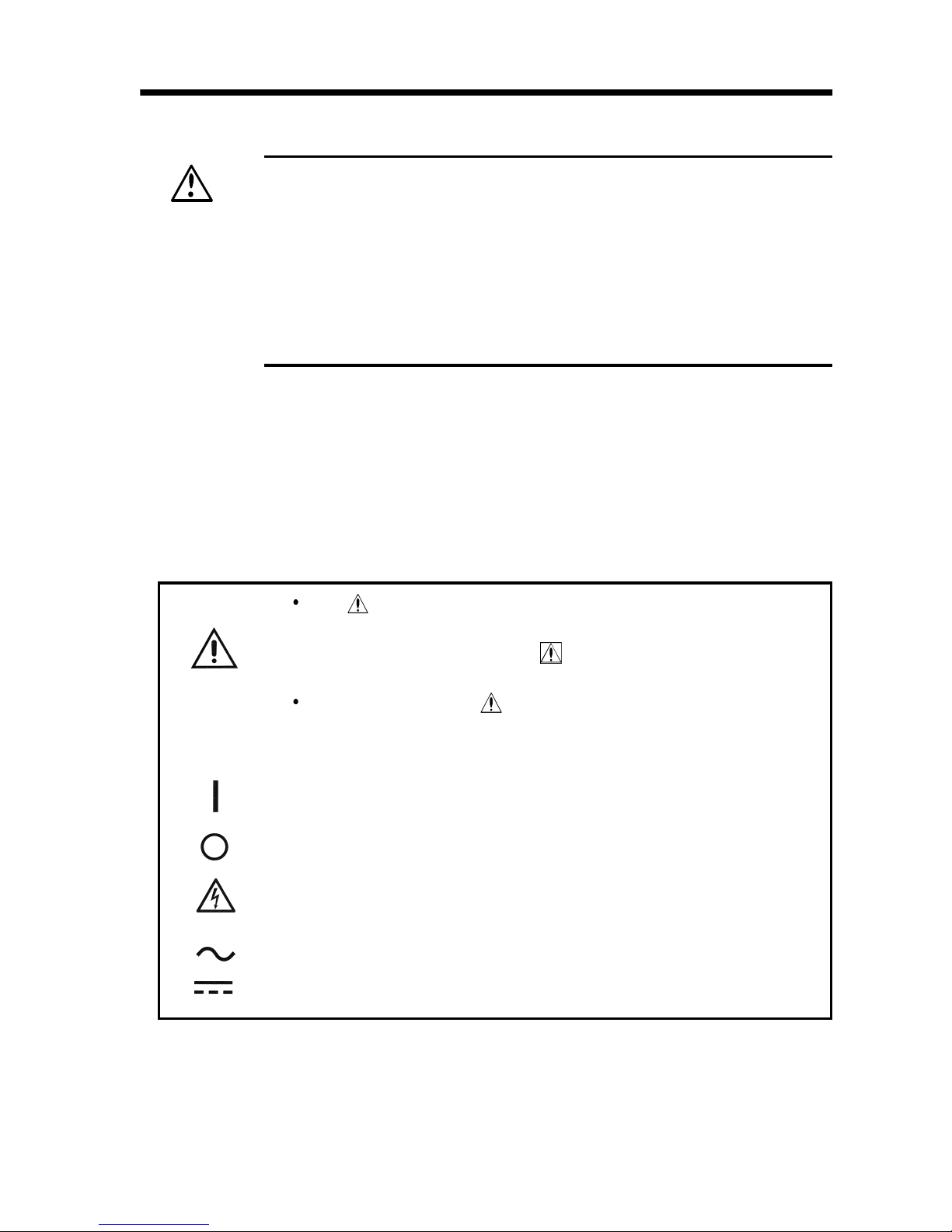
Safety Symbols
The symbol printed on the product indicates that the
user should refer to a corresponding topic in the
manual (marked with the
symbol) before using the
relevant function.
In the manual, the symbol indicates particularly
important information that the user should read before
using the product.
Indicates the ON side of the power switch.
Indicates the OFF side of the power switch.
Indicates that dangerous voltage may be present at
this terminal.
Indicates AC (Alternating Current).
Indicates DC (Direct Current).
SafetyNotes
This manual contains information and warnings essential
for safe operation of the product and for maintaining it in
safe operating condition. Before using the product, be sure
to carefully read the following safety notes.
Page 11
iv
_____________________________________________________________________
Safety Notes
______________________________________________________________
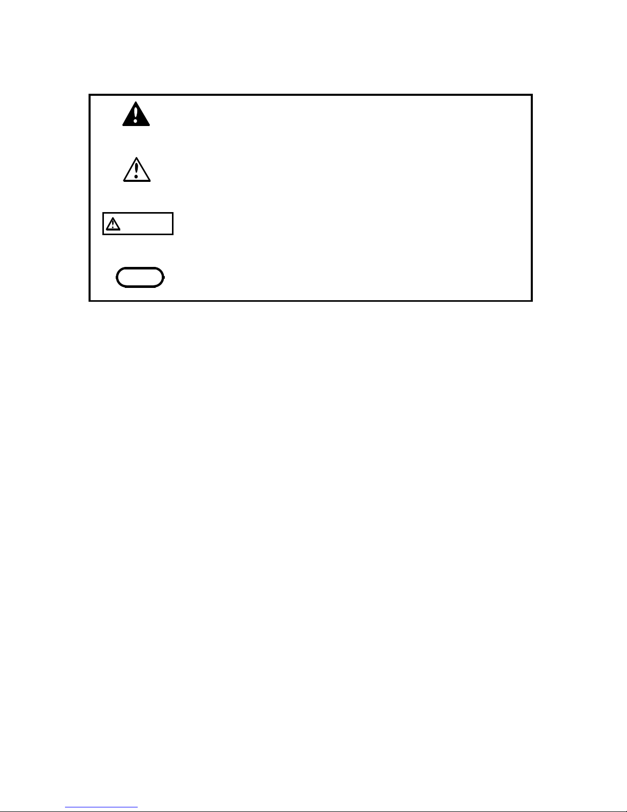
DANGER
Indicates that incorrect operation presents an extreme
hazard that could result in serious injury or death to
the user.
W
ARNING
Indicates that incorrect operation presents a
significant hazard that could result in serious injury or
death to the user.
CAUTION
Indicates that incorrect operation presents a
possibility of injury to the user or damage to the
product.
NOTE
Advisory items related to performance or correct
operation of the product.
The following symbols in this manual indicate the relative
importance of cautions and warnings.
Page 12
v
_____________________________________________________________________
Safety Notes
______________________________________________________________
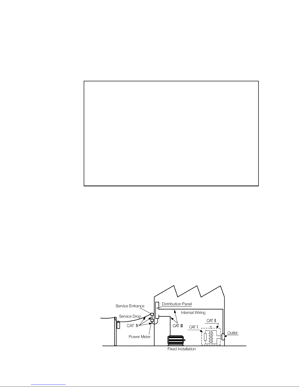
CAT I
Secondary electrical circuits connected to an AC
electrical outlet through a transformer or similar
device.
CAT II
Primary electrical circuits in equipment connected
to an AC electrical outlet by a power cord (portable
tools, household appliances, etc.)
CAT III
Primary electrical circuits of heavy equipment
(fixed installations) connected directly to the
distribution panel, and feeders from the distribution
panel to outlets.
CAT IV
The circuit from the service drop to the service
entrance, and to the power meter and primary
overcurrent protection device (distribution panel).
Measurement categories (Overvoltage categories)
This product complies with CAT I safety requirements.
To ensure safe operation of measurement product, IEC
61010 establishes safety standards for various electrical
environments, categorized as CAT I to CAT IV, and called
measurement categories. These are defined as follows.
Higher-numbered categories correspond to electrical
environments with greater momentary energy. So a
measurement device designed for CAT III environments can
endure greater momentary energy than a device designed for
CAT II. Using a measurement product in an environment
designated with a higher-numbered category than that for
which the product is rated could result in a severe accident,
and must be carefully avoided.
Never use a CAT I measuring product in CAT II, III, or IV
environments. The measurement categories comply with the
Overvoltage Categories of the IEC60664 Standards.
Page 13

vi
_____________________________________________________________________
Safety Notes
______________________________________________________________
f.s.
(maximum display value or scale length)
The maximum displayable value or the full length of the
scale.
This is usually the maximum value of the currently
selected range.
rdg.
(reading or displayed value)
The value currently being measured and indicated on the
measuring product.
dgt.
(resolution)
The smallest displayable unit on a digital measuring
product, i.e., the input value that causes the digital
display to show a "1".
Accuracy
We define measurement tolerances in terms of f.s. (full
scale), rdg. (reading) and dgt. (digit) values, with the
following meanings:
Page 14
vii
_____________________________________________________________________
Notes on Use
______________________________________________________________
DANGE
R
To avoid electric shock, do not remove the product's
case. The internal components of the product carry
high voltages and may become very hot during
operation.
WARNING
Before using the product, make sure that the insulation
on the test probes is undamaged and that no bare
conductors are improperly exposed. Using the product
under such conditions could result in electrocution.
Replace the test probes specified by Hioki .
Do not use the product where it may be exposed to
corrosive or combustible gases. The product may be
damaged or cause an explosion.
Do not use the product where it may be exposed to
corrosive or combustible gases. The product may be
damaged or cause an explosion.
Notes on Use
Follow these precautions to ensure safe operation and to
obtain the full benefits of the various functions.
Page 15
viii
_____________________________________________________________________
Notes on Use
______________________________________________________________
CAUTION
This product is not designed to be entirely water- or dustproof. To avoid damage, do not use it in a wet or dusty
environment.
This product should be installed and operated indoors only,
between 0 and 40
80% RH or less. Do not use the unit
in direct sunlight, dusty conditions, or in the presence of
corrosive gases.
Do not store or use the product where it could be exposed
to direct sunlight, high temperature or humidity, or
condensation. Under such conditions, the product may be
damaged and insulation may deteriorate so that it no longer
meets specifications.
Do not use the product near a device that generates a
strong electromagnetic field or electrostatic charge, as
these may cause erroneous measurements.
To avoid damage to the product, protect it from vibration or
shock during transport and handling, and be especially
careful to avoid dropping.
To avoid electrocution, turn off the power to all devices
before pluggingor unplugging any of the interface
connectors. Be sure to connect properly to avoid shortcircuit.
Because external I/O INT.GND terminal, RS-232C
connector frame, ground terminal and analog output GND
terminal are grounded, all equipment connected with GND
terminals are grounded. Use caution when handling. If the
equipment has an electric potential against the earth, a
short-circuit accident may occur.
Page 16

1
_____________________________________________________________________
Outline
______________________________________________________________
Chapter 1
Outline
1.1 Product Introduction
1.2 Features
HIOKI 3154 DIGITAL MΩ HiTESTER performs insulation
resistance testing on components and equipment using
direct current voltage. Comparator and timer functions
facilitate easy and accurate insulation resistance testing.
Equipped with six selectable test voltages and external I/O,
RS-232C interface and analog output terminal, HIOKI 3154
DIGITAL MΩ HiTESTER proves its efficiency and
versatility from laboratory to production and inspection line
testing.
(1) Easy Testing in accordance with safety standards
Select from six test voltages from 25 V to 1000 V.
Pass/Fail judgment function comparing measured value
by setting lower limit value and timer function support
wide variety of insulation resistance testing according to
safety standards.
(2) Easy-to-read display
High definition LED display
Page 17

2
_____________________________________________________________________
Outline
______________________________________________________________
(3) Saves Setting Conditions
Saves up to ten testing conditions including lower limit
value to quickly change conditions for various
standards.
Also restarts with values saved at power shutdown when
power is turned on.
(4) External Interface
External I/O outputs signals according to 3154 status
and inputs start/stop signals. Additional test conditions
can be selected.
Records extended insulation resistance fluctuations
using analog output.
(5) Equipped with RS-232C Interface
Use personal computer for automated testing and
recording test results. Optional 9442 PRINTER
provides measurement data printing.
(6) Optional Push Switch Probe
9299 SWITCHED PROBE enables efficient manual
testing.
(7) Automatic Discharge Function
Automatically discharges any charge buildup in
measured object after testing.
TEST lamp blinking during discharge indicates
discharge status.
Protects equipment from possible damage during
successive insulation resistance testing.
Page 18
3
_____________________________________________________________________
Outline
______________________________________________________________
1
2
4
3
6
5 7
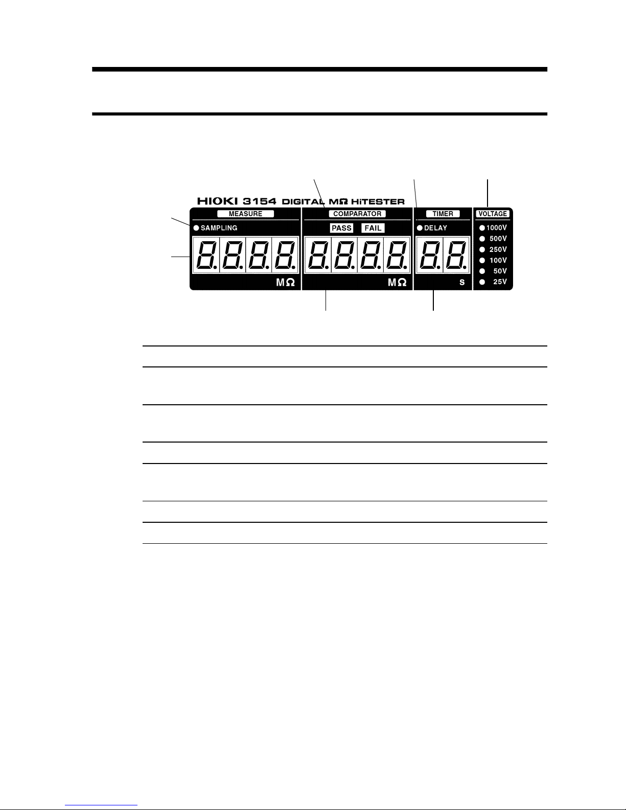
1. Sampling lamp Blinks during resistance measurement.
2. Measurement value
display
Displays measured resistance value.
3. Judgment result
display lamp
Displays comparator PASS/FAIL results.
4. Lower limit display Displays comparator lower limit value.
5. DELAY lamp (Delay
time setting lamp)
On when delay time is set.
6. Timer display Displays test duration or delay time.
7. Test voltage display Displays test voltage.
1.3 Controls and Functions
1.3.1 Displays
Page 19
4
_____________________________________________________________________
Outline
______________________________________________________________
1
6 7 8 9 10 11
2 543
13 1412 15
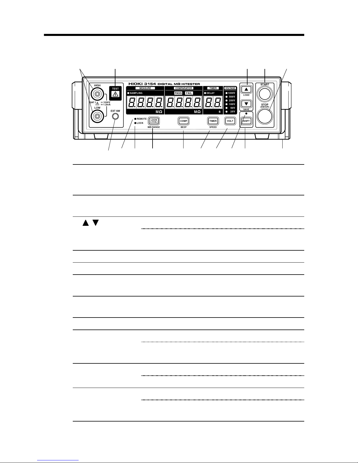
1. Measurement
terminals
Connect test probes. High voltage occurs
between terminals continuously electrically
connected to rear panel measurement terminals.
2. TEST lamp Turns on during testing. Blinks during
discharging buildup in tested object.
3. / key Press to change settings.
LOAD/SAVE
key
Press SHIFT key - LOAD/SAVE key to save and
load setting conditions.
4. START key Press to start testing.
5. STOP key Press to terminate testing or to confirm settings.
6. EXT.SW
terminal
Switch signal terminal for optional 9299
SWITCHED PROBE.
7. REMOTE lamp Turns on when communicating with personal
computer via RS-232C.
8. LOCK lamp Turns on when key lock is engaged.
9. LOCK key Press to engage or disengage key lock.
MΩ RANGE
key
Press SHIFT key - MΩ RANGE key to change to
and from auto range/manual range.
10. COMP key Press to set comparator.
BEEP key Press SHIFT key - BEEP key to set beep sound.
11. TIMER key Press to set test duration and delay time.
SPEED key Press SHIFT key - SPEED key to set
measurement speed.
1.3.2 Front Panel
Page 20
5
_____________________________________________________________________
Outline
______________________________________________________________
12. VOLT key PRESS to set test voltage.
13. SHIFT lamp Turns on when SHIFT key is pressed.
14. SHIFT key Press to engage shift.
When SHIFT key is pressed, shift is engaged and
SHIFT lamp turns on. Press again to disengage
shift.
When shift is engaged, functions displayed in
blue below keys become valid.
15. Handle/Stand Adjust handle to use as a stand.
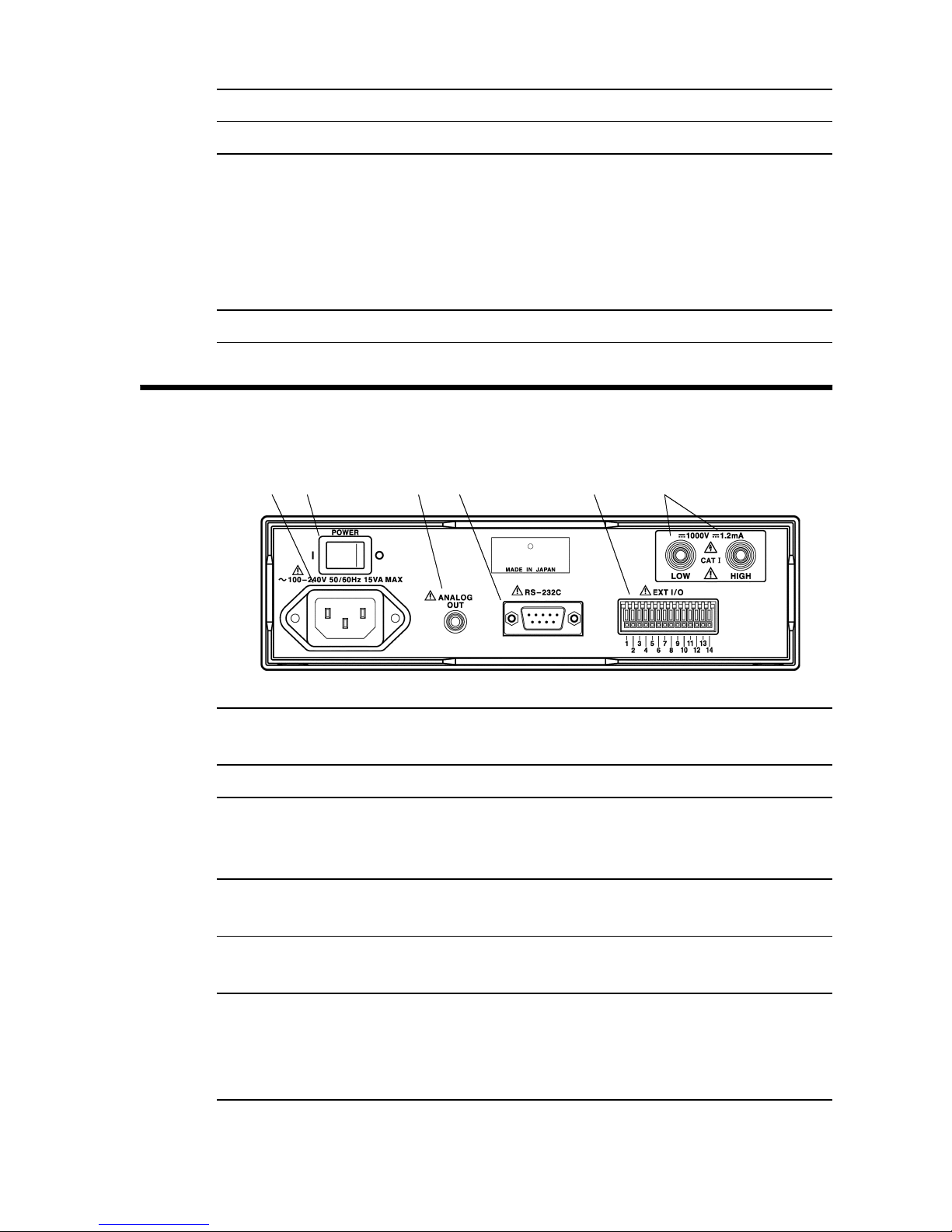
21 3 4 5 6
1. Power supply
connector
Terminal to connect power cord. (Internal fuse
type)
2. POWER switch Turns power ON/OFF.
3. Analog output
terminal
Converts measured resistance value and
outputs voltage.
Use to connect 9094 OUTPUT CORD.
4. RS-232C terminal Use to connect RS-232C for remote operation
or optional 9442 PRINTER.
5. External I/O
terminals
Outputs 3154 status and inputs start/stop and
test voltage switching signals.
6. Rear
measurement
terminals
Connect test probes. High voltage occurs
between terminals. Continuously electrically
connected to front panel measurement
terminals.
1.3.3 Rear Panel
Page 21

6
_____________________________________________________________________
Outline
______________________________________________________________
Page 22
7
_____________________________________________________________________
Preparation for Testing
______________________________________________________________
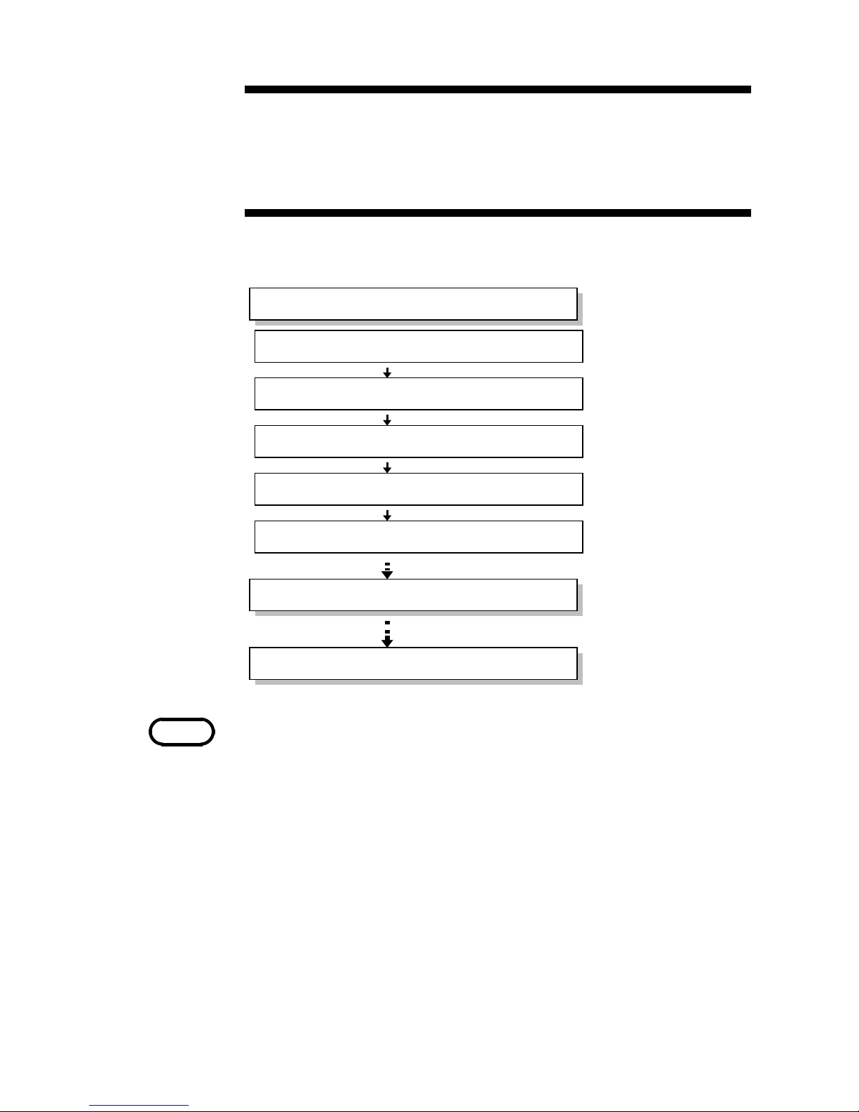
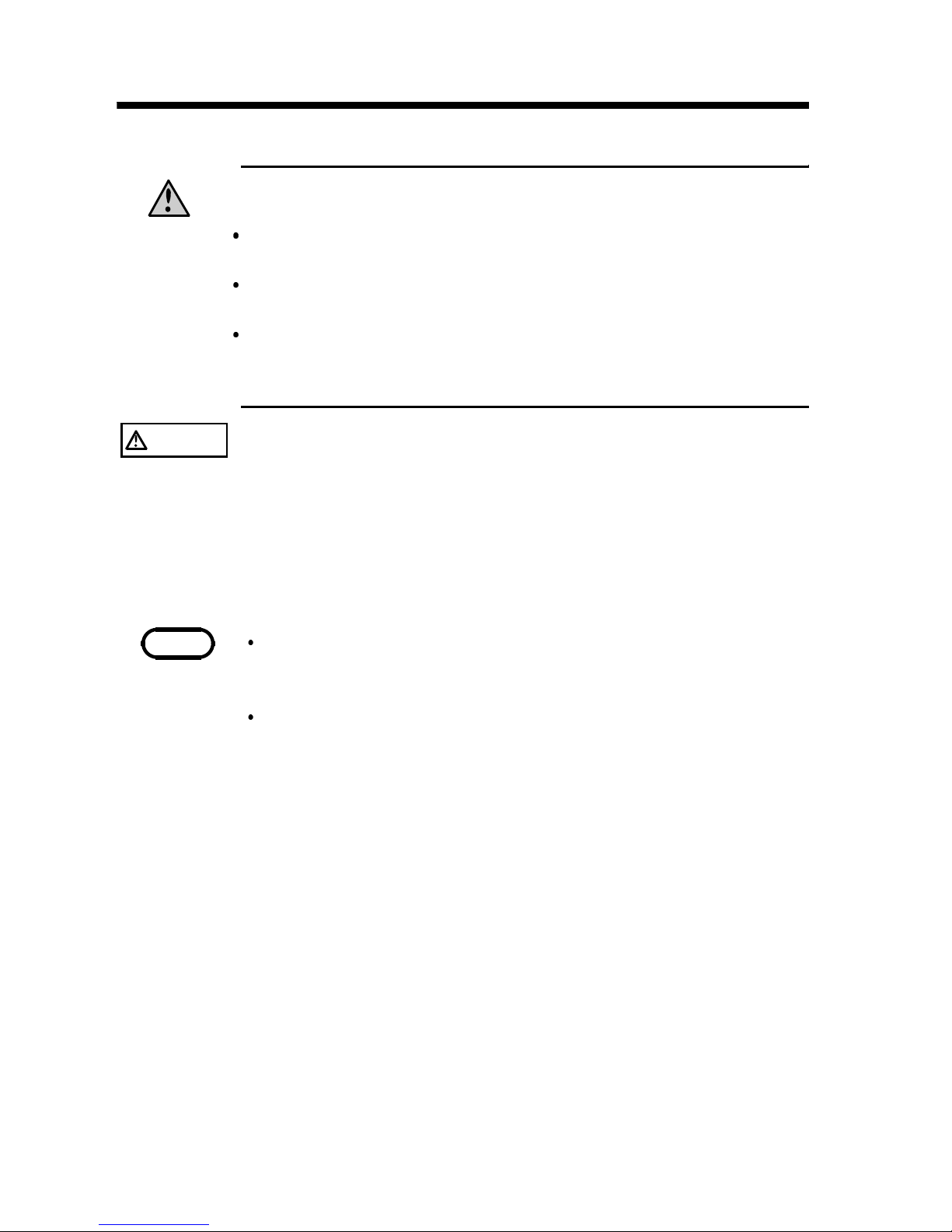
Connecting Cord and Probes
Using Handle
Connecting to Equipment to be tested
Connecting Power Cord
Powering On and Off the Unit
See 2.1.
Preparation for Testing
Testing
Setting Basic Testing Conditions
See 2.2.
See 2.3.
See 2.4.
See 2.5.
See Chapter 3.
See Chapter 4.
NOTE
See 4.7 Testing with SWITCHED PROBE to conduct
measurement using 9299 SWITCHED PROBE.
Chapter 2
Preparation for Testing
Before testing preparation, read each note carefully.
Page 23

8
_____________________________________________________________________
Preparation for Testing
______________________________________________________________
WARNING
The unit is constructed so as to be connected to a
ground line via a three-core power cord that is supplied
with the unit.
To avoid electric shock and ensure safe operation,
connect the power cable to a grounded (3-contact)
outlet.
Before turning the product on, make sure the source
voltage matches that indicated on the product's power
connector. Connection to an improper supply voltage
may damage the product and present an electrical
hazard.
To avoid damaging the pow er cord, grasp the plug, not
the cord, when unplugging the cord from the power
outlet.
(example)
Insert the plug into
the outlet
2.1 Connecting Power Cord
Connecting Power Cord
(1) Verify that the 3154 POWER switch is OFF ( O ).
(2) Connect power cord supplied with the 3154 to power
supply connector located in the back.
(3) Connect power cord plug to grounded dual polarity
power outlet.
Page 24
9
_____________________________________________________________________
Preparation for Testing
______________________________________________________________
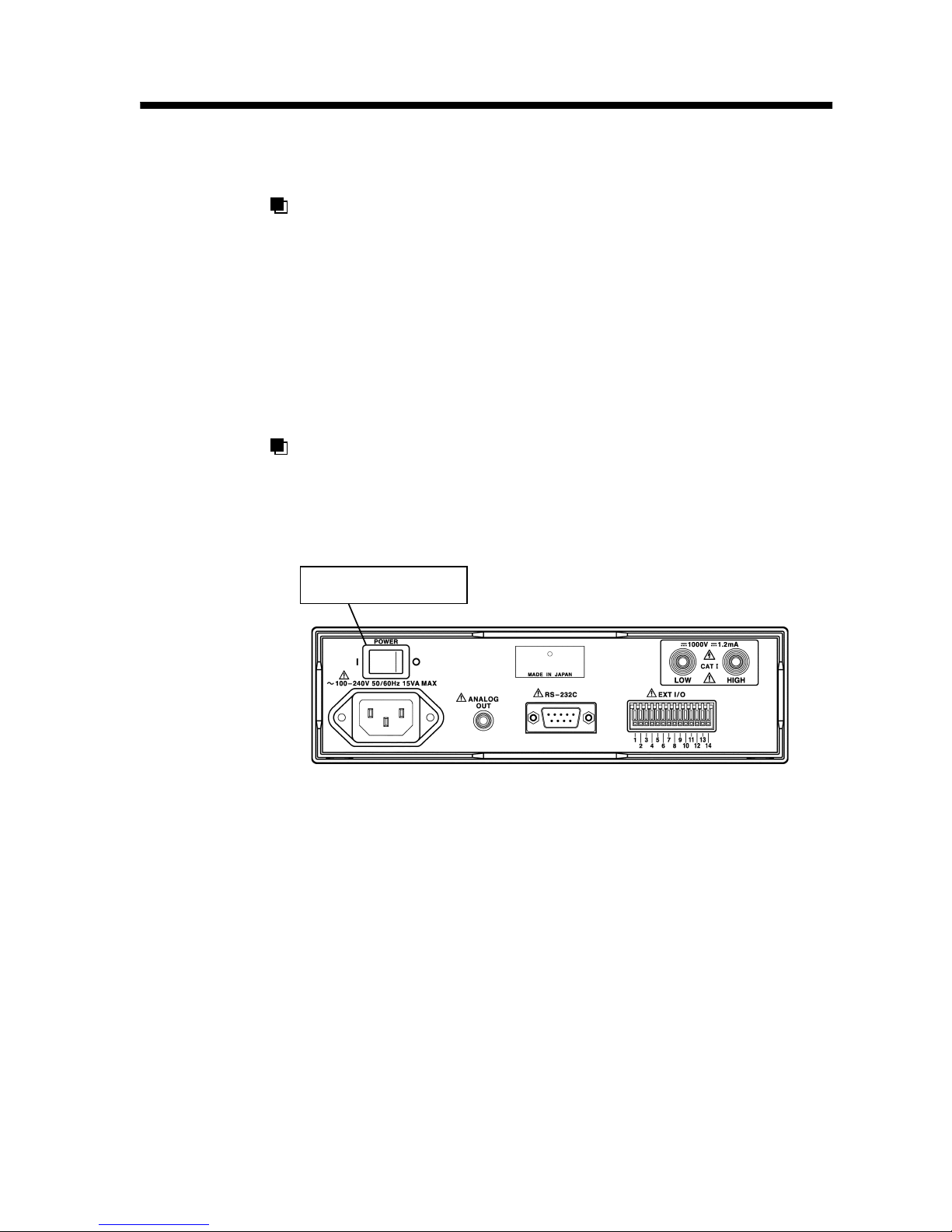
POWER switch
2.2 Powering On and Off the Unit
Powering On
(1) Turn POWER switch ON ( I ) on the rear panel.
(2) All displays light up displaying product name and
software version.
(3) Returns to normal READY status for use with settings
saved prior to turning power off.
For stable measurement readings, allow thirty minutes
or more to warm up after turning power on.
Powering Off
Turn POWER switch OFF (O) on the rear panel. Settings
are saved when turning power off.
Page 25
10
_____________________________________________________________________
Preparation for Testing
______________________________________________________________
WARNING
To avoid the risk of electric shock, be sure to press the
3154 STOP key and confirm that the TEST lamp is off
before connecting/disconnecting probes. Do not keep
power on equipment to be tested when connecting
probes.
Before using the product, make sure that the insulation
on the test probes is undamaged and that no bare
conductors are improperly exposed. Using the product
under such conditions could result in electrocution.
Replace the test specified by Hioki .
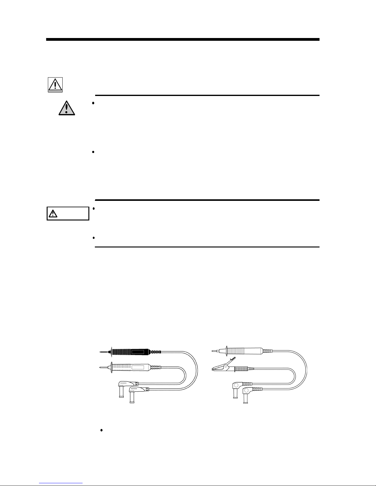
CAUTION
For safety reasons, only use the optional CONNECTION
CORD, 9257 and TEST PROBEs, 9289 or 9294, provided
with the unit for measurement.
To avoid damaging the probes, do not bend or pull the probes.
9289 TEST PROBE 9294 TEST PROBE
2.3 Connecting Cord and Probes
(9257, 9289, 9294)
Although measurement terminals are both located in the front
and rear panels, both cannot be used at the same time. Leave
one side disconnected.
The 9257, 9289 and 9294 come with protective caps. Take the
caps off before connecting to 3154.
Connect black probe to LOW terminal and red probe to HIGH
terminal. Tightly insert probes all the way into the terminals.
See 8.4 Options and specifications, about the 9257
CONNECTION CORD.
Page 26
11
_____________________________________________________________________
Preparation for Testing
______________________________________________________________
CAUTION
When using the handle as a stand for the device, do not
press down too hard on the device as this can damage the
handle.
When interface cable, etc. is connected to the rear panel,
keep the unit flat to avoid damaging the cable.
When setting the unit to show display upward, tilt it
carefully to avoid damaging power cord by excessive
stress.
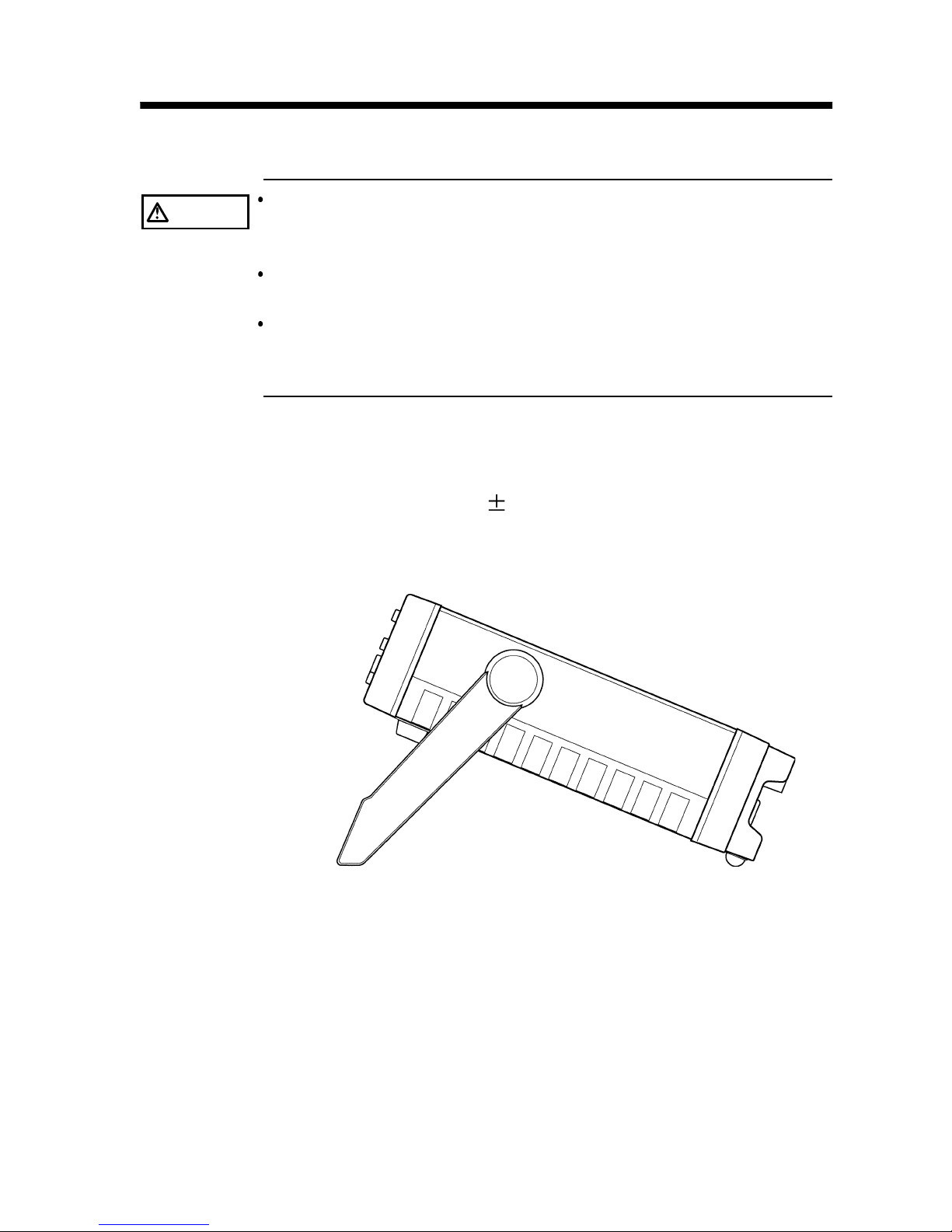
2.4 Using Handle
Handle can be used as stand. Pull out the side, turn and
press in the handle.
Handle turns each 22.5
.
When setting flat, turn the handle over the unit.
Page 27
12
_____________________________________________________________________
Preparation for Testing
______________________________________________________________
WARNING
Observe the follow ing precautions to avoid electric
shock.
To avoid the risk of electric shock, turn power off on
equipment to be tested.
Before and after testing, do not touch equipment to be
tested and probe tip when TEST lamp is on or blinking.
Afte r testing is complete, confirm that the 3154 TEST
lamp is off before disconnecting probe from equipment
to be tested.
CAUTION
When connecting probe to equipment to be tested under
TEST status, verify the voltage occurred on the display
before connecting. Improper voltage may damage
equipment to be tested.
NOTE
When 3154 is in READY status, approximately a voltage
greater than +10 V volts in equipment to be tested initiates
TEST lamp, and blinks after connecting probe.
When connecting the LOW side of the measurement terminal
with the earth, there is a possibility that a measurement value
smaller than the actual value may be displayed. As such,
when conduction an insulation test with the earth, be sure to
ground the measurement object, and connect the HIGH side of
the terminal with the earth.
2.5 Connecting to Equipment to be tested
Connect probe to equipment to be tested.
Page 28
13
_____________________________________________________________________
Setting Basic Testing Conditions
______________________________________________________________
Setting comparator
Setting timer
Setting lower limit value
Setting test mode
Setting test duration
Setting delay time
・See Chapter 2
Pre
p
aration for Testing.
・
When using PASS/FAIL
judgment, set lower limit
value. See 3.2.1.
・
When using PASS/FAIL
judgment, set test mode.
See 3.2.2.
・
Set test duration. See 3.4.1
・
Set delaytime. See 3.4.2.
・See Cha
p
ter 4 Testing.
Setting test voltage
・
Select from 25 V to 1000 V.
See 3.1.
Setting resistance range
・
Set either manual range
(4 types) or auto range.
See 3.3.
Setting sampling rate
・
Set FAST or SLOW.
See 3.5.
Preparation for testing
Setting testing conditions
Start testing
Chapter 3
Setting Basic Testing
Conditions
The below shows setting items and procedures.
Page 29
14
_____________________________________________________________________
Setting Basic Testing Conditions
______________________________________________________________
CAUTION
Setting at improper voltage may damage equipment to be
tested.
Test voltage can be set by external I/O. In this case, the
3154 test voltage display lamp stays on displaying previous
voltage until testing starts after setting voltage from external
I/O. Do not start the test simply by confirming the voltage
display lamp, as unexpected voltage may be generated.
Start the test only after you have confirmed the test voltage
setting of the external I/O.
Test voltage indicator lamp
NOTE
During READY status, TEST status, test voltage can be verified
by blinking test voltage indicator lamp.
When selecting test voltage with external I/O, test voltage
cannot be set by key press. Set all external I/O VOLT0 to
VOLT2 to LOW or HIGH (not necessary to connect) use key
press for setting.
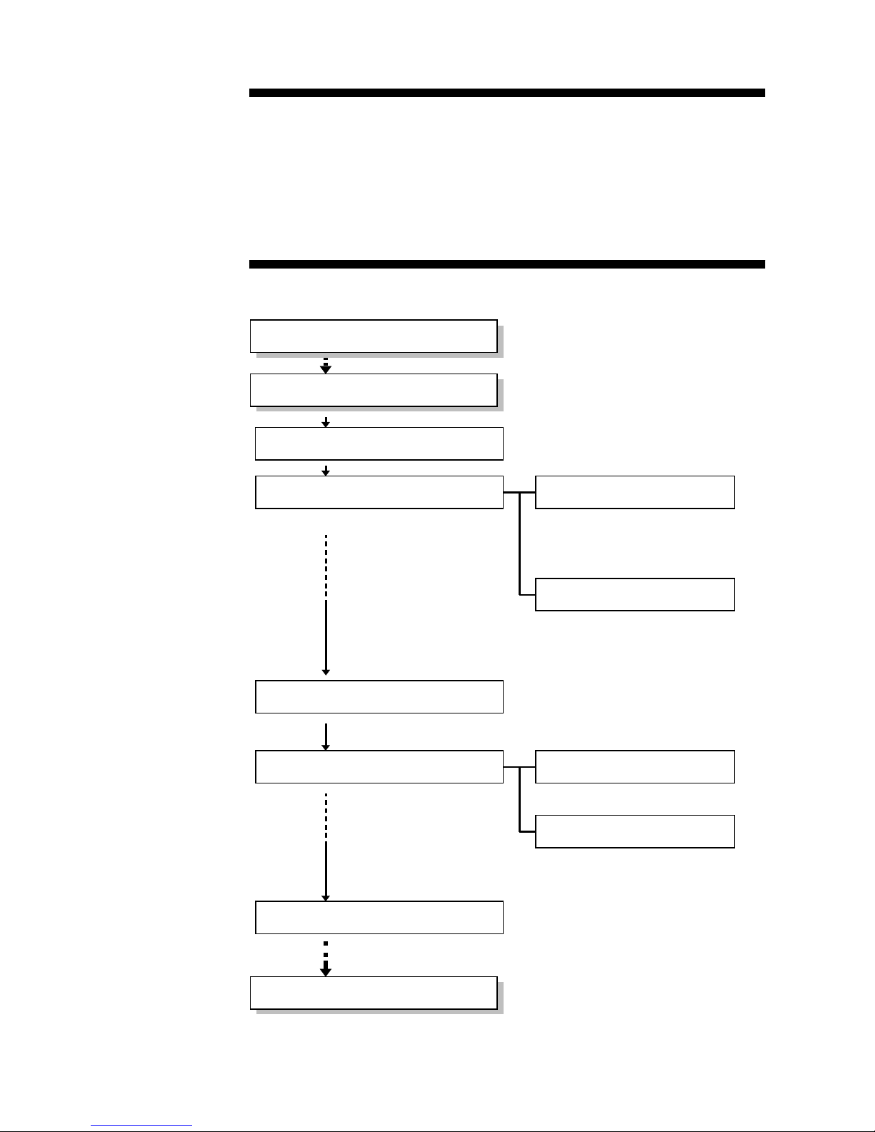
3.1 Setting Test voltage
Set and select test voltage from 25 V to 1000 V. To set
comparator at each voltage, selecting another voltage
automatically changes lower limit value.
Setting test voltage
(1) When READY status (with TEST lamp off or blinking),
press VOLT key to initiate test voltage display lamp to
blink. (Setting)
(2) Press
/ key to select test voltage to start and test
voltage indicator lamp starts blinking.
(3) Press STOP key or VOLT key to complete setting with
test voltage indicator lamp no longer blinking but on
and returns to READY status.
Page 30
15
_____________________________________________________________________
Setting Basic Testing Conditions
______________________________________________________________
Lower limit value(MΩ) Resistance range
0.1/0.2/0.3/0.4/0.5/0.6/0.7/0.8/0.9/1/2 2MΩ
2/3/4/5/6/7/8/9/10/20 20 MΩ
20/30/40/50/60/70/80/90/100/200 200 MΩ
200/300/400/500/600/700/800/900/1000/2000
/3000/4000 (Limited to test voltage 500 V,
1000 V for 3000/4000)
2000 MΩ
(4000 MΩ range for
500 V, 1000 V)
NOTE
RS-232C Interface provides an option to set lower limit value at
any value within the measurement range in addition to the
displayed selection. Once designated lower limit value is
switched to another by key press, use RS-232C Interface to reset
at designated lower limit value.
3.2 Setting and Verifying Comparator
3.2.1 Setting Lower Limit Value
When comparator is set, set lower limit value and test
mode. Execute PASS/FAIL judgment by comparing value
set as lower limit value and measurement value.
Lower limit value determines resistance range for setting
(manual range). See the chart below for possible
combination of lower limit value and resistance range for
setting.
When auto range is selected for resistance range, lower
limit value is not limited at any value.
Improper combination of lower limit value and resistance
range results in incorrect PASS/FAIL judgment.
See 3.3 Setting and Verifying Resistance Range to set
resistance range.
Lower limit value chart
Page 31

16
_____________________________________________________________________
Setting Basic Testing Conditions
______________________________________________________________
Setting Lower Limit Value
(1) During READY status, press COMP key and lower
limit value indicator starts blinking.
(2) Press
/ key to select and display lower limit. (Unit
is[MΩ
]
)
"----" appears when comparator is not set.
(3) Press either STOP key or COMP key to confirm lower
limit value.
Display automatically returns to test mode setting
display. Continue with test mode setting. See 3.2.2.
Not Setting Lower Limit Value
(Not Setting Comparator)
(1) During READY status, press COMP key and
comparator lower limit value indicator starts blinking.
(2) Press both
key and key at the same time to
display "----" blinking or press either
/ key several
times to display "----" blinking.
(3) Press STOP key or COMP key.
(4) Returns not to test mode setting status but to READY
status. Lower limit value indicator displays "----".
Page 32

17
_____________________________________________________________________
Setting Basic Testing Conditions
______________________________________________________________
NOTE
Set test mode adjusted to test voltage.
When lower limit value is set at "----"(not using comparator),
test mode setting is not available.
Ready status does not display test mode.
3.2.2 Setting and Verifying Test mode
Setting Test mode
(1) After selecting lower limit value (other than "----") at
lower limit value setting status, test mode setting status
automatically appears by pressing either STOP key or
COMP key.
Which ever display previously set, FAIL StOP or
Continue starts blinking.
(2) Press
/ key to switch FAIL StOP/ContinuE.
FAIL STOP mode: FAIL judgment stops testing.
CONTINUE mode: FAIL judgment does not interfere
with testing.
(Testing stops by STOP key press
or by time set by timer.)
(3) Press STOP key or COMP key to confirm selected
mode.
After determining selected mode, automatically returns
to READY status and displays selected lower resistance
value.
Confirming Test mode
When lower limit value (excluding "----") is set, follow the
instructions below to confirm test mode.
(1) Press COMP key twice when READY status. Confirm
that designated test mode display starts blinking.
(2) After confirming, press COMP key to return to READY
status.
Page 33

18
_____________________________________________________________________
Setting Basic Testing Conditions
______________________________________________________________
A
UtO
3.3 Setting and Verifying Resistance
Range
Resistance range comes with four types of manual range, 2
MΩ,20MΩ, 200 MΩ, 2000 MΩ(4000 MΩ at 500/1000
V) and auto range.
Auto range may require some time before measurement
value is displayed because range has to shift immediately
after testing starts. Set resistance range to manual range
according to measuring object to eliminate time to
display.
Setting Resistance Range
(1) Press SHIFT key, then LOCK key when READY status.
Display as shown below appears and lower limit value
indicator blinks and displays one of the following
"AUtO", "2", "20", "200", "2000". ("4000" at 500/1000
V)
(2) Each
/ key press switches blinking display.
(3) When desired resistance range is displayed, press STOP
key or LOCK key to confirm. After determining, returns
to READY status.
When manual range is selected and measurement value is
over 2000 count, "O.F." (Over flow) is displayed.
When measurement value is less than 190 count,
"U.F." (Under flow) is displayed.
Confirming Resistance Range
(1) Press SHIFT key, then LOCK key when READY status
to display selected resistance range blinking.
(2) After confirming, press STOP key or LOCK key to
return to READY status.
Page 34

19
_____________________________________________________________________
Setting Basic Testing Conditions
______________________________________________________________
3.4 Setting and Verifying Timer
3.4.1 Setting and Verifying Test Duration
Test duration is the time to apply voltage, measure
resistance and perform PASS/FAIL judgment.
Same Test duration setting is applicable at any test voltage.
When setting at auto range, if the test time is set at a short
time period, there is a possibility that test may finish
without displaying a measurement value because of a range
shift. To prevent this from occurring, please set a test time
longer than 2 seconds (for 25 V or 50 V, 1.5 seconds)
when setting at auto range.
Setting Test duration
(1) During READY status, press TIMER key and timer
indicator starts blinking.
(2) Press
/ key to display desired test duration at timer
indicator.
Hold
/ key down to speed up adjustment of timer
control. (units in [seconds], setting range: 0.5 s to 99 s)
"--" is displayed when test duration is not set.
(3) Press STOP key or TIMER key to confirm test duration.
Indicator automatically switches and displays delay time
setting status and timer display and DELAY lamp start
blinking. To set delay time, see 3.4.2.
Page 35

20
_____________________________________________________________________
Setting Basic Testing Conditions
______________________________________________________________
When Not Setting Test duration
(1) During READY status, press TIMER key. When timer
indicator is blinking, press both
key and key at
the same time to display "--" blinking or hold down
either
key or key to display "--" blinking.
(2) When "--" is blinking, press STOP key or TIMER key.
(3) After setting delay time, returns to READY status. Timer
indicator displays "--" .
In this case, testing is performed with no time limit.
Page 36

21
_____________________________________________________________________
Setting Basic Testing Conditions
______________________________________________________________
DELAY lam
p
3.4.2 Setting and Verifying Delay Time
Delay time is used to set test duration lock out time for
timer function and PASS/FAIL judgment by comparator
immediately after testing starts and voltage is applied.
Measurement value is displayed.
Same delay time setting is applicable at any test voltage.
For details, read 3.4.3 Determining Delay time.
Setting Delay Time
(1) During test duration setting status, press STOP key or
TIMER key to automatically change and display delay
time settings display.
Timer display and DELAY lamp start blinking.
(2) Press
/ key to display desired delay time on timer
indicator.
Hold
/ key down to speed up adjustment of timer
control. (units in [seconds], setting range: 0.1 s to 99 s)
(3) Press STOP key or TIMER key to confirm delay time.
After determining, automatically returns to READY
status and DELAY lamp is turned on.
Timer indicator displays selected test duration.
When Not Setting Delay Time
(1) During delay time setting status, press both
key and
key at the same time to display "--" blinking or hold
down either
key or key to display "--" blinking.
(2) When "--" is blinking, press STOP key or TIMER key.
(3) Returns to READY status. In this case, testing is
performed as 0 second delay time.
Page 37

22
_____________________________________________________________________
Setting Basic Testing Conditions
______________________________________________________________
Confirming Delay Time
During READY status, delay time is not displayed. Follow
the direction below to confirm delay time.
(1) During READY status, press TIMER key twice.
Selected delay time is displayed with DELAY lamp
blinking. When delay time is not set, "--" is displayed
with DELAY lamp blinking.
(2) After confirming, press TIMER key to return to
READY status.
Page 38

23
_____________________________________________________________________
Setting Basic Testing Conditions
______________________________________________________________
TEST lam
p
Time
r
Resistance
measurement
Comparator
Test voltage
App
rox. 0.3 s
Confirmed test duration
Dischargetime
Approx.
10 V
Time
OFF ON
OFF
START STOP
Blinkin
g
OFF
Test duration timer ON
OFF
OFF
OFF
PASS/FAIL judgment
Measuring・Displayin
g
OFF
OFF
3.4.3 Determining Delay Time
When equipment to be tested contains capacitance,
measurement value is low due to current charging
capacitance immediately after test voltage is applied
resulting in FAIL judgment by comparator. To avoid
incorrect FAIL judgment, set delay time.
While charging capacitance, time is required for applied
voltage to reach test voltage standard value. Because test
duration countdown begins after time elapses when
confirmed as delay time, it provides an option for a test
with test duration excluding charging time (during low
voltage).
Determine delay time by examining measurement value
fluctuation after start of testing and applied voltage rising
waveform (observed with optional tester).
Without Delay Time
Page 39

24
_____________________________________________________________________
Setting Basic Testing Conditions
______________________________________________________________
Confirmed
dela
y
time
TEST lam
p
Time
r
Resistance
measurement
Comparator
Test voltage
App
rox. 0.3 s
Confirmed test
duration
Dischargetime
Approx.
10 V
Time
OFF ON
OFF
START STOP
Blinkin
g
OFF
Delay time
timer ON
Test duration
timer ON
OFF
OFF
OFF
PASS/FAIL
judgment
Measurin
g
・
Displayin
g
OFF
OFF
Voltagegraduallyrises chargingcapacitance.
With Delay Time
Page 40

25
_____________________________________________________________________
Setting Basic Testing Conditions
______________________________________________________________
FAST
SLOW
3.5 Setting Sampling Rate
Choose from two sampling rates, FAST or SLOW.
Sampling resistance and displaying value with FAST is ten
times per second and with SLOW one time per second.
When measurement value fluctuates, select SLOW for
effective reading.
During TEST status, SAMPLING lamp blinking rate alter
according to sampling rate. To confirm selected sampling
rate check the lamp blinking rate.
Setting Sampling Rate
(1) During READY status, press SHIFT key and then
TIMER key.
Display appears as shown below to display sampling
rate FAST or SLOW blinking.
(2) Press
/ key to switch blinking display.
(3) When selected sampling rate is displayed, press STOP
key or TIMER key to confirm. After confirming,
returns to READY status.
Page 41

26
_____________________________________________________________________
Setting Basic Testing Conditions
______________________________________________________________
Test voltage
500 V
Lower limit value
1MΩ
Test duration
5s
Test mode
FAIL STOP
Delay time
ON
Judgment beep sound
END(see 5.1.1)
3.6 Example Test Condition Setting
The example shows READY status setting display after
setting is complete before START key is pressed.
Measurement value display decimal position may differ
case by case.
When returning to READY status without changing
previous setting condition, the last measurement value and
PASS/FAIL judgment result are displayed again.
(1) When testing with comparator and timer and judging
PASS/FAIL with beep sound, set as instructed below.
Test mode, delay time and beep sound setting are not
displayed during READY status.
Start testing with above settings. While timer is ON, FAIL
judgment stops test followed by an approximately two
second continuous beep sound. When test duration timer
ends, short beep sound repeats three times.
When FAIL STOP mode is set, completing test duration
with timer indicates PASS judgment.
Single continuous beep sound indicates FAIL and repeating
beep indicates PASS judgment.
Page 42

27
_____________________________________________________________________
Setting Basic Testing Conditions
______________________________________________________________
Test voltage
500 V
Lower limit value
No limit
Test duration
OFF
Test mode −−−
Delay time
OFF
(2) Exclusively for insulation resistance measurement, set as
instructed below.
Page 43

28
_____________________________________________________________________
Setting Basic Testing Conditions
______________________________________________________________
Page 44

29
_____________________________________________________________________
Testing
______________________________________________________________
NOTE
See 4.7 Testing with 9299 SWITCHED PROBE to conduct
measurement using 9299 SWITCHED PROBE.
Chapter 4
Testing
HIOKI 3154 DIGITAL MΩ HiTESTER is equipped with
READY status, setting status and TEST status.
(1) READY status
Stands ready for testing. TEST lamp is either OFF or
blinking during READY status.
(2) Setting status
Sets various test settings. Each setting display blinks
during setting status.
(3) TEST status
To test with voltage between measurement terminals.
TEST lamp is ON during TEST status.
Page 45

30
_____________________________________________________________________
Testing
______________________________________________________________
・During READY status, press START key to start testing.
・Switches to TEST status and TEST lamp is ON.
ON
OFF
Delaytime
CONTINUE mode
Lower limit
value
OFF
FAIL
judgment
OFF
ON
ON
Test mode
Designated Test
duration passes.
FAIL STOP
mode
Test
duration
OFF
Press STOP
key.
・Returns to READY status.
Continues to display measurement value and judgment result
(when lower limit value is set).
・For safety, discharge charge buildup in tested equipment.
During discharge, TEST lamp blinks.
1. Resistance measurement 2. Delay time countdown
1. Resistance measurement 2. PASS/FAIL judgment
3. Test duration countdown
Ends testing.
ON
4.1 Test Flow
Simple test flow chart
Page 46

31
_____________________________________________________________________
Testing
______________________________________________________________
WARNING
To avoid the risk of electric shock,c do not touch
equipment to be tested, probe tips and measurement
terminals when TEST lamp is on or blinking.
Do not touch equipment to be tested, probe tips and
measurement terminals immediately after testing. High
voltage charge may result in electric shock.
To avoid the risk of electric shock, After testing,
proceed with discharge function to discharge charge in
tested equipment. (See 4.6.)
START key
NOTE
To start and end testing, in addition to keys, 3154 DIGITAL
MΩ HiTESTER is equipped with external I/O, RS-232C and
probes with switch. Different ways can be used to start and to
end testing.
Check and see if test probes are securely connected before
testing.
When external I/O STOP signal is set to LOW, testing does not
start.
4.2 Start Testing
During READY status, press START key to start testing in
TEST status with TEST lamp ON.
Page 47

32
_____________________________________________________________________
Testing
______________________________________________________________
NOTE
Approximately 0.3 s is required after pressing START key to
start resistance measurement and delay time countdown.
See 4.4 to display measurement value.
4.3 During Testing (TEST status)
When switching to TEST status, the 3154 applies test
voltage to equipment to be tested.
1. When delay time is set, starts resistance measurement
and delay time countdown.
For details, see 3.4.3 Determining Delay time.
(1) Starts resistance measurement and displays
measurement value. (unit: MΩ)
(2) During delay time countdown, DELAY lamp blinks.
After completing delay time countdown, DELAY
lamp goes OFF.
2. After passing delay time (or without setting delay time),
starts resistance measurement, PASS/FAIL judgment and
test duration countdown.
(1) Starts resistance measurement and displays
measurement value. (unit: MΩ)
(2) Following resistance measurement, performs
PASS/FAIL judgment by comparator.
When measurement value < lower limit value, FAIL
lamp turns ON.
When measurement value
lower limit value, PASS
lamp turns ON.
See 5.1.1 to set beep sound for judgment.
When lower limit value is not set, lower limit value
indicator displays "----" without PASS/FAIL
judgment.
(3) Timer indicator indicates test duration countdown.
When test duration is not set, indicator displays "--".
Page 48

33
_____________________________________________________________________
Testing
______________________________________________________________
4.4 Measurement Value Display
Tips for measurement value display
When resistance range is set to auto range, range shifts
immediately after testing starts and only decimal point moves
and measurement value is not displayed on measurement
value display. To eliminate time for decimal point to move,
switch resistance range to manual range. (See 3.3 for setting.)
When using the test duration timer at auto range, testing will
finish without displaying a measurement value during a range
shift if the set time set has past. Please set the test duration
timer longer than 2 seconds (for 25 V or 50 V, 1.5 seconds)
when setting at auto range.
When set at auto range, measurement value fluctuates
betweentworesistanceranges. Inthiscaseswitchresistance
range to manual range. (See 3.3 for setting.)
Display "O.F." indicates overflow. In auto range, "O.F." is
displayed when going over measurement range maximum
value and in manual range when over each range maximum
value.
Display "U.F." indicates underflow. In manual range,
excluding 2 MΩ range, "U.F." is displayed when going below
190 dgt. Does not display in auto range.
Insulation resistance is known to be unstable. This is not a
difficulty although measurement values may not be consistent
depending on the equipment to be tested.
When measurement values fluctuate and are unable to read,
set sampling rate to SLOW. (See 3.5)
Larger capacitance in equipment to be tested tends to result in
a wider range of measurement value fluctuations. See "Limit
determined by capacitance contained in equipment to be
measured" in Chapter 8.
Page 49

34
_____________________________________________________________________
Testing
______________________________________________________________
WARNING
To avoid the risk of electric shock, disconnect probe
from tested object after TEST lamp is turned off after
testing is complete.
4.5 Completing Testing
(1) After ending testing by one of three following ways,
returns to READY status.
Press STOP key to stop testing.
Designated testing time passes and stops testing.
When test mode is set at FAIL STOP mode, FAIL
judgment stops testing.
(2) After returning to READY status, previously displayed
measurement value and judgment result display lamp at
testing completion continue to display.
(3) TEST lamp may not turn off and continue to blink after
testing is complete indicating discharging any charge
buildup in tested object and the 3154.
Proceed with discharge by following instruction in 4.6
Automatic Discharge.
(4) After TEST lamp is turned off, remove probes from
tested equipment.
Page 50

35
_____________________________________________________________________
Testing
______________________________________________________________
NOTE
Safe to set and verify test condition setting or press START key
to restart testing while TEST lamp is still blinking.
When the 3154 power supply is turned OFF, discharge
resistance is approximately 12 MΩ .
4.6 Automatic Discharge
When insulation resistance test is performed on equipment
to be tested containing capacitance, test voltage load is
charged during testing which may result in electric shock.
Use automatic discharge function to discharge buildup
charge through the 3154 internal circuit.
After testing, follow the instructions below to discharge.
(1) End testing without removing both test probes from
tested equipment.
(2) The 3154 internal discharge resistance unit enables
automatic discharge of the buildup charge in the tested
equipment.
(3) During discharge, TEST lamp blinks.
(4) When voltage goes below approximately 10 V, TEST
lamp turns off.
Internal discharge resistance is approximately 2 MΩ .
Larger amount of capacitance requires longer discharge
time.
Page 51

36
_____________________________________________________________________
Testing
______________________________________________________________
1
3
2
1. Push switch
Functions as external switch for the
3154 START key and STOP key.
2. Switching signal lead plug
Connects to the 3154 EXT SW
terminal.
3. Measurement plug
Connect to the 3154 measurement
terminal.
NOTE
The same operations are applicable in both TEST status and
READY status.
9299 SWITCHED PROBE can be used as an ordinary probe
when switch signal lead plug is not connected to EXT SW
terminal.
When external I/O STOP signal is set to LOW or the 3154
STOP key is pressed, testing cannot be initiated.
4.7 Testing with 9299 SWITCHED PROBE
Optional 9299 SWITCHED PROBE permits control starting
and stopping 3154 operation while probe is held in hand.
Before testing, set push switch probe mode to either trigger
mode or continue mode. (See 4.7.2 to set mode.) The
3154 initial setting is set to continue mode.
(1) Continue Mode
Only when pressing ON switch, continues TEST status.
During READY status, press switch to start testing.
Release switch to terminate testing.
(2) Trigger Mode
Press switch to start testing. TEST status continues
even after releasing switch. Press switch to terminate
testing in TEST status.
Page 52

37
_____________________________________________________________________
Testing
______________________________________________________________
WARNING
Inserting switch signal lead plug into terminal may turn
TEST lamp on causing high voltage to occur in
measurement terminal and probe tip. To avoid the risk
of electric shock, before connecting switch signal lead
plug to 3154, make sure to disconnect test probe from
measurement terminal.
Do not press switch on probe when connecting and
disconnecting probe. Unintentional generation of high
voltage may result in electric shock and/or equipment
damage.
4.7.1 Connecting 9299 SWITCHED PROBE
9299 SWITCHED PROBE requires another test probe. Use
either 9257 CONNECTION CORD, 9289 or 9294 TEST
PROBEs.
Follow these steps carefully to connect probe.
(1) Connect 9299 switch signal lead plug to EXT SW terminal.
Insert plug securely so that plug metal tip is not exposed at
all.
When TEST lamp is on after inserting plug, press switch on
9299 or press 3154 STOP key to turn TEST lamp off.
(2) After confirming TEST lamp is turned off, connect 9299
measurement plug to front panel HIGH or LOW
measurement terminal.
(3) Connect connection cord (9257) or another test probe (9289
or 9294) to the other front panel measurement terminal.
(4) When 3154 is in READY status, press switch on 9299 and
verify that 3154 TEST lamp is turned on.
When disconnecting 9299 from the 3154, disconnect test
probe first and signal lead last.
Page 53

38
_____________________________________________________________________
Testing
______________________________________________________________
Trigger mode
Continue mode
4.7.2 Setting 9299 SWITCHED PROBE
Select either continue mode (cont) or trigger mode (trig) to
set 9299 SWITCHED PROBE.
Operation Setting
(1) During READY status, press SHIFT key then press and
hold VOLT key for approximately two seconds or
longer to display "SPECIAL".
(2) Press ▲/▼ key to display "9299 ProbE".
(3) Press STOP key and "9299 Cont" or "9299 triG" appear
blinking to show display to select and set Push Switch
probe mode setting. (Display "9299" does not blink.)
(4) Press
/ key to switch blinking display with "Cont"
or "triG".
(5) Display blinking "Cont" to switch to continue mode and
"triG" to trigger mode and press STOP key. After
pressing STOP key, probe operation mode is confirmed
and returns to READY status.
Page 54

39
_____________________________________________________________________
Other Functions
______________________________________________________________
Key Lock Function
System Reset
Setting Judgment BeepSetting and Verifying Beep
Sound
Saving and Loading Test
Conditions
・
See 5.1.1.
Setting Beep Sound During
Key Press
Saving Test Conditions
Loading Test Conditions
・
See 5.1.2.
・
See 5.2.1.
・
See 5.2.2.
・
See 5.3.
・
See 5.4.
Chapter 5
Other Functions
3154 is equipped with the following functions.
Page 55

40
_____________________________________________________________________
Other Functions
______________________________________________________________
5.1 Setting and Verifying Beep Sound
5.1.1 Setting Judgment Beep Sound
When PASS/FAIL judgment is performed with comparator
and timer, select beep sound from following four options.
PASS : Beeps for PASS judgment.
FAIL : Beeps for FAIL judgment.
End : Beeps when test duration timer ends.
OFF : No beep sound.
Setting Judgment Beep Sound
(1) During READY status, press SHIFT key and then
COMP key.
Display appears blinking to indicate selected beep
sound option. (Example below shows when beep sound
is OFF.)
(2) Each
/ key press switches blinking displays
"PASS", "FAIL", "End", "OFF" to indicate options.
(3) Press either STOP key or COMP key to confirm the
option. After confirming, automatically returns to
READY status.
Verifying Judgment Beep Sound
(1) During READY status, press SHIFT key and then
COMP key. Verify that selected beep sound option
indicator is blinking.
(2) After verifying, press either STOP key or COMP key
and returns to READY status.
Page 56

41
_____________________________________________________________________
Other Functions
______________________________________________________________
BeepOFF
BeepON
5.1.2 Setting Beep Sound During Key Press
Select from beep sound options to set beep ON or OFF
during key press.
Setting Beep Sound ON or OFF.
(1) During READY status, press SHIFT key then press and
hold VOLT key for approximately two seconds or
longer to display "SPECIAL".
(2) Press ▲/▼ key to display "KEY bEEP".
(3) Press STOP key and "bEEP ON" or "bEEP OFF"
appears blinking to select and set beep sound during
key press. (Display "bEEP" does not blink.)
(4) Each
/ key press switches blinking displays "ON"
and "OFF".
(5) Select blinking indicator "ON" to set beep sound on and
"OFF" to set off and press STOP key to confirm option.
After confirming, automatically returns to READY
status.
Page 57

42
_____________________________________________________________________
Other Functions
______________________________________________________________
5.2 Saving and Loading Test Conditions
5.2.1 Saving Test Conditions
All 3154 configured test conditions, up to ten settings can
be saved in internal memory excluding the following four
conditions.
Special Conditions
9299 SWITCHED PROBE operation mode
Changing RS-232C Interface options (personal
computer/printer)
Beep sound setting during key press
External I/O TEST signal OFF timing setting
Settings to be selected with external I/O VOLT 0 - 2
signals
Analog output setting
Read saved memory by operation instructed in 5.2.2
Loading Test Conditions.
Page 58

43
_____________________________________________________________________
Other Functions
______________________________________________________________
Saving Test Conditions
(1) During READY status, press SHIFT key and then
key. Following indicator appears displaying a number
blinking to display save setting. The number identifies
test condition setting to be saved.
When save setting display appears, the number
displayed is determined as described below.
Displays the smallest number available if not all ten
numbers are used.
Displays number 10 if all ten numbers are already in
use to identify and save settings.
(2) Press
/ key to select desired number from option 1
to 10 to save settings. (When a saved option is
selected, overwrites previous test condition settings.)
(3) Press STOP key. Display "SAVE NO." blinks
approximately two seconds or returns to READY status
completing saving test conditions.
To return to READY status without saving test
conditions, press any key except STOP key and
/
key.
Page 59

44
_____________________________________________________________________
Other Functions
______________________________________________________________
NOTE
When loading with test voltage setting signal input through
external I/O, following loaded conditions; test voltage, lower
limit value and test mode become invalid defaulting to external
I/O setting even after pressing START key.
When no condition setting is saved, loading display shows "--"
in stead of number. In this case pressing
/ key does not
switch displays.
5.2.2 Loading Test Conditions
Saved test conditions can be loaded from internal memory.
Loading saved test conditions
(1) During READY status, press SHIFT key and then
key. Following indicator appears displaying a number
blinking. The number identifies saved test condition
setting.
(2) Press
/ key to select option to load. Does not
display numbers not in use.
(3) Press STOP key. Display "LOAD No." appears blinking
approximately two seconds and returns to READY
status completing loading test condition.
To return to READY status without loading test
conditions, press any key except STOP key and
/
key.
(4) Each indicator displays loaded conditions.
Page 60

45
_____________________________________________________________________
Other Functions
______________________________________________________________
LOCK lam
p
LOCK ke
y
5.3 Key Lock Function
Execute key lock to disable front panel key switch
operations excluding START key, STOP key and 9299
SWITCHED PROBE switching operations.
Executing Key Lock
During READY status, press and hold LOCK key for
approximately two seconds or longer.
When key lock status, LOCK lamp on the left of LOCK
key is on.
Disengaging Key Lock
During READY status, press and hold LOCK key for
approximately 2 s or longer.
Page 61

46
_____________________________________________________________________
Other Functions
______________________________________________________________
Test voltage 25 V
Lower limit value OFF (displays [----])
Test mode Continue mode
Test duration OFF (displays [--])
Delay time OFF (displays [--])
Resistance range Auto range
Judgment beep sound FAIL
Sampling rate FAST
Push switch probe mode Continue mode
Beep sound during key press ON
Connection with RS-232C PC
External I/O TEST signal OFF timing SLOW
External I/O VOLT 0 to 2 signals VOLT
Analog output setting FULL RANGE
5.4 System Reset
System reset is used to set all test conditions back to initial
factory settings. All saved test conditions are cleared by
system reset.
Executing system reset
(1) During READY status, press SHIFT key then press and
hold VOLT key for approximately two seconds or
longer to display "SPECIAL".
(2) Press ▲/▼ key several times to display "rESEt".
(3) Press STOP key and all indicators are turned on. After
displaying "Product name" and "Software version",
returns to READY status completing system reset.
Factory Settings
Page 62

47
_____________________________________________________________________
External Interface
______________________________________________________________
Chapter 6
External Interface
6.1 Controlling 3154 with External I/O
External I/O terminal connector board is located in the back
and enables signal input for START
STOP test voltage
control and signal output for 3154 status (TEST status,
etc.)
comparator judgment results.
All signal leads are isolated through a photocoupler from
other parts. (Not isolated between signal leads)
Use external power supply (5 to 30 VDC).
Internal power supply 5 V and GND are output by external
I/O terminal enabling simple external I/O functions. Use
caution because external I/O, RS-232C connector and
analog output terminal are not isolated.
Page 63

48
_____________________________________________________________________
External Interface
______________________________________________________________
Pin number IN/OUT Signal name
1, 2 OUT INT.GND
3 IN EXT.COM
4 OUT FAIL
5 OUT PASS
6 OUT TEST
7 IN VOLT2
8 IN VOLT1
9 IN VOLT0
10 IN STOP
11 IN START
12 IN EXT.DCV
13, 14 OUT INT.DCV
114
START Set signal to LOW to enable same function as
pressing 3154 START key. To perform start up
edge detection, it requires more than 60 ms when
set to LOW. Locking on LOW does not release
continuous START signal input. In this case STOP
signal is accepted for input.
STOP Set signal to LOW to enable same function as
pressing 3154 STOP key. To perform start up edge
detection, it requires more than 60 ms when set to
LOW. Locking on LOW does not accept "all test
start" for input.
VOLT0,VOLT1,
VOLT2
Combination of these signals enables selection from
six test voltages (including comparator) options or
from seven saved test condition options. See 6.1.5.
TEST During TEST status, selects LOW. Set with options
either to wait until after discharging charge in tested
equipment after completing test or not to wait and
returns to HIGH. See 6.1.6.
PASS Selects LOW when comparator gives PASS
judgment.
FAIL Selects LOW when comparator gives FAIL judgment.
EXT.DCV Terminal to supply power from external equipment.
Power supply voltage range is 5 to 30 VDC.
Supplies power also by connecting with INT.DCV
terminal.
6.1.1 Terminal Connector Board/Signal Wires
Page 64

49
_____________________________________________________________________
External Interface
______________________________________________________________
EXT.COM Terminal to connect to external equipment GND.
Also connects with INT.GND terminal.
INT.DCV
、
INT.GND
Outputs 3154 internal power supply (5 VDC) and
internal GND. Use to enable simple external I/O
functions. Not isolated.
GND terminal is connected with power supply cord
ground lead.
NOTE
Beep sound can be set to ON/OFF during START and STOP
signal input. Same setting applies and performs same operation
as beep sound during key press.
To avoid starting test by mistake, hold STOP signal LOW and
set it back to HIGH right before setting START signal to LOW.
In this case, be sure to set STOP signal to HIGH at least 1 ms
before START signal is to set to LOW.
Page 65

50
_____________________________________________________________________
External Interface
______________________________________________________________
Input signal
Active LOW input
Maximum applied voltage
Voltage of EXT.DCV terminal
HIGH level
Voltage of EXT.DCV terminal or open
LOW level
0.3 VDC or less
Output signal
Open corrector output
Maximum load voltage
DC+30 V
(when not using EXT.DCV terminal)
Maximum output current
60 mADC/1 signal (when LOW level)
Output voltage
5 VDC
Maximum load current
100 mADC
6.1.2 Electric Specifications
Input signal specifications
(Applied signal names: START, STOP, VOLT0, VOLT1,
VOLT2)
Output signal specifications
(Applied signal names: PASS, FAIL, TEST)
EXT.DCV terminal maximum input voltage: 30 VDC input
to EXT.COM terminal
Internal power supply output
(between INT.DCV and INT.GND terminals)
Output signal is a photocoupler open corrector output.
3154 is internally connected to EXT.DCV terminal at 4.7
kΩ pull up resistance.
Page 66

51
_____________________________________________________________________
External Interface
______________________________________________________________
External
DC power
supply
Output voltage
High level
Low level
Output current
10 mA
Output current
40 mA
Output current
60 mA max.
5V 5V 0.9 V 1.1 V 1.2 V
12 V 12 V 0.9 V 1.1 V 1.2 V
24 V 24 V 0.9 V 1.1 V 1.2 V
When Not Using EXT.DCV Terminal
When connecting and loading directory to output terminal
without using EXT.DCV terminal, refer to the chart below
for external DC power supply to be connected for another
direct loading and output signal voltage, output current.
Page 67

52
_____________________________________________________________________
External Interface
______________________________________________________________
CAUTION
In order to avoid risk of damaging the unit, do not input
excessive voltage or current above standard to external I/O
terminal. See "6.1.2 Electric Specifications" to set standard
voltage and current.
5 VDC is output between internal DC power
supply(INT.DCV) and INT.GND. Maximum current is 100
mA. To prevent product damage, do not connect to
external circuit consuming more than 100 mA.
Power supply voltage to external DC power supply
(EXT.DCV, EXT.COM terminals) is 5 to 30 VDC.
To prevent product damage, do not apply voltage over 30
VDC. In order to activate circuit, connect power supply
with at least 50 mA output capacity.
In order to avoid risk of electric shock, turn equipment
power supply OFF before connecting and disconnecting
wires to terminal board. Carefully handle wiring and see
that no wire is disconnected and exposing conducting
elements including the unit body etc.
To prevent product and equipment damage, when using
relay, be sure to install back electromotive force absorption
diode.
Do not short circuit terminals other than designated
terminals. Internal short circuit may occur when sheathing
is exposed beyond standard length.
6.1.3 Connecting External I/O Terminal
Page 68

53
_____________________________________________________________________
External Interface
______________________________________________________________
Recommended
wire
Single strand
0.65 mm dia (AWG#22)
Multi-strand
0.32 mm
2
(AWG#22)
Usable limits Single strand
0.32 to 0.65 mm dia. (AWG #28 to #22)
Multi-strand
0.08 to 0.32 mm
2
(AWG #28 to #22)
Standard insulation stripping length 10 mm
Button pressing tool Blade screwdriver
(tip width 2.6 mm)
(1) Push the tab with a flatblade screwdriver or similar.
(2) While keeping the tab depressed, insert a stripped wire
into the connector opening.
(3) Release the tab to lock the wire.
Page 69

54
_____________________________________________________________________
External Interface
______________________________________________________________
CAUTION
Signal wire insulation is used to cut down interference
between signals. Be sure to apply protective grounding to
external equipment to be connected to avoid risk of
damaging insulation.
Maximum photocoupler low level output current is 60 mA.
When more than 60 mA current is required, current
amplifier transistor circuit and other external power supply
devices must be connected externally.
Terminal board pin number
11
10
9
8
7
6
5
4
12
13
14
2
1
3
Connected to power cord ground lead
4.7 kΩ(1/4W)
External powe
r
supply (COM)
EXT.COM
Internal powe
r
supply (5 V)
INT.DCV
Externalpowe
r
supply
(5 V to 30 V)
EXT.DCV
Internal powe
r
supply
(5 V) (GND)
INT.GND
*
:Connect when using internal DC power supply (5 V).
*
*
START
STOP
VOLT0
VOLT1
VOLT2
TEST
PASS
FAIL
External I/O terminal circuit
shematic diagram shown below.
6.1.4 External I/O Terminal Circuit
Page 70

55
_____________________________________________________________________
External Interface
______________________________________________________________
Test voltage
Signal
25 V 50 V 100 V 250 V 500 V 1000 V Invalid
VOLT0 L H L H L H L H
VOLT1 H L L H H L L H
VOLT2 H H H L L L L H
Test condition
Signal
No.1 No.2 No.3 No.4 No.5 No.6 No.7 Invalid
VOLT0 L H L H L H L H
VOLT1 H L L H H L L H
VOLT2 H H H L L L L H
6.1.5 Settings to be selected with VOLT 0 to 2
signals
External I/O VOLT 0 to 2 signals allow the following two
selections to be selected. At factory setting, test voltage and
comparator (VOLT) are selected.
(1) Selecting test voltage and comparator (VOLT)
Select test voltage (including comparator) according the
chart below.
"H" stands for HIGH, "L" for LOW.
(2) Loading saved test conditions (LOAd)
Select from saved test conditions No.1 through No. 7
according to the chart below. To select from saved test
conditions, see 5.2.1.
"H" stands for HIGH, "L" for LOW.
Page 71

56
_____________________________________________________________________
External Interface
______________________________________________________________
Setting content with VOLT 0 to 2 signals
(1) During READY status, press SHIFT key and press and
hold VOLT key approximately two seconds or longer to
display "SPECIAL".
(2) Press▲/▼key to display "VOLt SIGnAL"
(3) Press STOP key to display either "VOLt VOLt" or
"VOLt LOAd" blinking and display appears to set
content settable with VOLT 0 to 2 signals. ("VOLt"
does not blink.)
(4) Press
/ key to switch blinking displays "VOLt" and
"LOAd".
(5) After selecting "VOLt" or "LOAd", press STOP key to
confirm option and returns to READY status.
Verifying setting
Just to verify setting, just go to setting display. After
verifying blinking indicator, press STOP key to return to
READY status.
Page 72

57
_____________________________________________________________________
External Interface
______________________________________________________________
6.1.6 Setting TEST Signal OFF Timing
The following shows two options when external I/O TEST
signal output returns from LOW to HIGH after completing
test. Factory setting is set to SLOW.
(1) SLOW (SLO)
After completing test, maintains LOW (same status
during test) until voltage goes down to approximately
10 V in tested equipment during discharge.
(2) FAST (FASt)
Regardless of discharging status, returns to HIGH
almost simultaneously after completing test.
Setting TEST signal OFF timing
(1) During READY status, press SHIFT key and press and
hold VOLT key approximately two seconds or longer to
display "SPECIAL".
(2) Press▲/▼key to display "tESt SIGnAL"
(3) Press STOP key to display either "tESt SLO" or "tESt
FASt" blinking and display appears to set TEST signal
to OFF timing. ("tESt" does not blink.)
(4) Press
/ key to switch blinking displays "SLO" and
"FASt".
(5) After selecting "SLO" or "FASt", press STOP key to
confirm option and returns to READY status.
Verifying setting
Just to verify setting, just go to setting display. After
verifying blinking indicator, press STOP key to return to
READY status.
Page 73

58
_____________________________________________________________________
External Interface
______________________________________________________________
Sto
p
App
rox. 10 V
Test voltage
STOP
(Input)
TEST
(
Output
)
Occurrence
Sto
p
App
rox. 30 to 80 ms
Test voltage
STOP
(Input)
TEST
(
Output
)
Occurrence
TEST Signal OFF Timing
(1) When SLOW is selected
(2) When FAST is selected
Page 74

59
_____________________________________________________________________
External Interface
______________________________________________________________
Delay time OFF Resistance range Manual range
Start testing START signal End testing STOP signal
First judgment result PASS After second judgment result FAIL
TEST signal OFF timing SLOW
First Second
First Second
First measurement resultingin PASSjudgmen
t
Second and following measuremen
t
resultingin FAILjudgment
Continue to displa
y
FAILjudgment
Continue to
display
value from
f
inal test
Sto
p
Occurrence
Sto
p
Continue to display
value from previous
test
Continue to displayvalue fromprevious test
t
1
t
2
t
3
t
4
t
4
t
1
t
5
t
6
Clear
START
(Input)
TEST
(
Output
)
Test voltage
STOP
(Input)
Measurement
Measurement
value displa
y
PASS
(
Output
)
FAIL
(
Output
)
Timing Time
t
1
START signal range, STOP signal range
60 ms min.
t
2
Between START input and TEST signal output
80 ms max.
t
3
Between TEST signal output and measurement starting time
Approx. 250 ms
t
4
Sampling time
FAST 0.1 s/SLOW 1 s
t
5
Between STOP signal input and time when test voltage starts falling.
80 ms max.
t
6
Between time when test voltage stops and time when TEST
signal is disengaged.(HIGH)
Note: Reference value when measuring pure resistance 10 MΩ
Test voltage: 25 V
approx. 150 ms
Test voltage: 1000 V
approx. 600 ms
6.1.7 Timing Chart
To control test voltage from external I/O, set signal before
testing. Test voltage cannot be changed during testing.
TEST signal timing is synchronized with front panel TEST lamp.
Page 75

60
_____________________________________________________________________
External Interface
______________________________________________________________
Delay time OFF Resistance range Manual range
Start testing START signal End testing End of setting
time
First judgment result PASS After second judgment result FAIL
TEST signal OFF timing SLOW
First Second
First Second
Sto
p
Runnin
g
Sto
p
Continue to display value from previous test
t
1
t
3
t
4
t
4
Clear
START
(Input)
Test Duration
Measurement
Measurement
value displa
y
PASS
(
Output
)
FAIL
(
Output
)
t
5
TEST
(
Output
)
Sto
p
Occurrence
Sto
p
t
6
Test voltage
t
2
Continue to display
value from previous
test
First measurement resultingin PASSjudgmen
t
Second and following measuremen
t
resultingin FAILjudgment
Continue to displa
y
FAILjudgment
Continue to
display
value from
f
inal test
Timing Time
t
1
START signal range, STOP signal range 60 ms min.
t
2
Between START input and TEST signal output 80 ms max.
t
3
Between TEST signal output and measurement starting time Approx. 250 ms
t
4
Sampling time FAST 0.1 s/SLOW 1 s
t
5
Between time when test duration timer stops and time when
test voltage starts falling.
Approx. 20 ms
t
6
Between time when test voltage stops and time when TEST
signal is disengaged.(HIGH)
Note: Reference value when measuring pure resistance 10 MΩ
Test voltage:25 V
Approx. 150 ms
Test voltage:1000 V
Approx. 600 ms
The timing chart below shows timing between time to start and time
to complete testing under the following conditions.
Page 76

61
_____________________________________________________________________
External Interface
______________________________________________________________
Output
30 V max.
EXT.COM
60 mA max.
Output
30 V max.
60 mA max.
Rela
y
LED lam
p
EXT.COM
NOTE
When using relay, be sure to install back electromotive force
absorption diode.
EXT.DCV
30 V max.
Output
Connectingnegative logic output
EXT.COM
Output
INT.DCV
Output
EXT.COM
INT.GND
INT.GND
EXT.DCV
GND
Short circuit
Output
Short circuit
6.1.8 Output Signal Connection Example
(1) When Using as Open Collector Output
(2) When using external DC power connected to
EXT.DCV, EXT.COM terminals, HIGH (5 to 30 VDC)
and LOW signals are available between the output and
EXT.COM terminals.
(3) When using internal DC power, the signals between
INT.DCV and EXT.DCV, and between INT.GND and
EXT.COM will both short circuit, and HIGH (5 VDC)
and LOW signals are available between the output and
INT.GND terminals.
Page 77

62
_____________________________________________________________________
External Interface
______________________________________________________________
External
Power
30 V max.
EXT.DCV
Input
Transistor
3154
3154
Transistor
Short-Circuit
EXT.DCV
INT.DCV
Input
INT.GND
6.1.9 Input Signal Connection Example
Using transistor example shown bellow.
It is possible to use FET or external switch in stead of
transistor.
(1) When Using External DC Power
(2) When Using Internal DC Power
Page 78

63
_____________________________________________________________________
External Interface
______________________________________________________________
CAUTION
To avoid risk of damaging the unit and output cord, do not
input external voltage and current to analog output terminal.
Do not connect output cord plug to the 3154 measurement
terminal.
6.2 Analog Outputting
6.2.1 Connecting the 9094 OUTPUT CORD
Rear panel analog output terminal outputs direct voltage
proportional to resistance.
When connecting to recorder, etc., use input resistance over
1MΩ. Low input resistance results in incorrect readings.
Connect optional 9094 OUTPUT CORD shown below.
Page 79

64
_____________________________________________________________________
External Interface
______________________________________________________________
Test voltage
Resistance display
value
Output voltage (DC)
25 V, 50 V 0.000 MΩto 200 M
Ω
0Vto4V
100 V, 250 V 0.000 MΩto 2000 M
Ω
0Vto4V
500 V, 1000 V 0.000 MΩto 4000 M
Ω
0Vto4V
All test voltages
O.F. 4V
U.F. 0V
Resistance range Resistance display value
Output voltage
(DC)
2MΩ 0.000 MΩ to 2.000 MΩ 0Vto4V
20 MΩ 1.90 MΩ to 20.00 MΩ 0.38 V to 4 V
200 MΩ 19.0 MΩ to 200.0 MΩ 0.38 V to 4 V
2000 MΩ(100/250 V) 190 MΩ to 2000 MΩ 0.38 V to 4 V
4000 MΩ(500/1000V) 190 MΩ to 4000 MΩ 0.19 V to 4 V
All ranges
O.F. 4V
U.F. 0V
6.2.2 Analog Output
Analog output voltage output range come with the following
two options. During testing, analog output follows the 3154
measurement display timing. After completing testing,
analog output continues to output and hold final voltage.
(1) Outputs 0 to 4 V in all measurement resistance ranges
(FULL rAnGE)
Regardless of selecting auto range or manual range,
resistance display value in relation to output voltage is
showninthechartbelow. When0.000MΩ is
displayed 0 V is output. Outputs voltage proportional to
resistance until maximum value is displayed in each test
voltage measurement resistance range outputting 4
VDC.
(2) Output voltage according to each resistance range
(EACH rAnGE)
When resistance range is set to manual range, voltage is
output as described in the chart below. Outputs 4 V
when each each resistance maximum value is displayed.
When resistance range is set to auto range, voltage is
output as described in the (1) chart.
To set and verify resistance range, see 3.3.
Page 80

65
_____________________________________________________________________
External Interface
______________________________________________________________
6.2.3 Setting Analog Output
3154 Analog Output Setting
(1) During READY status, press SHIFT key and then press
and hold VOLT key approximately two seconds or
longer to display "SPECIAL".
(2) Press
/ key to display "A.OUt rAnGE".
(3) Press STOP key to show "FULL rAnGE" or "EACH
rAnGE" blinking.
(4) Press
/ key to switch blinking displays.
(5) After selecting "FULL rAnGE" or "EACH rAnGE",
press STOP key to confirm option and returns to
READY status.
Verifying setting
Just to verify setting, just go to setting display. After
verifying blinking indicator, press STOP key to return to
READY status.
Page 81

66
_____________________________________________________________________
External Interface
______________________________________________________________
Figure shows 9442 PRINTER connected with
9444 CONNECTION CABLE.
6.3 Outputting to Printer
Use optional 9442 PRINTER, 9444 CONNECTION
CABLE, 9443 AC ADAPTER and 1196 RECORDING
PAPER to print measurement values and judgments result
after completing testing.
9442 PRINTER
DPU-414 by SEIKO Electronic Industry, Co.
9443 - 0 1 AC ADAPTER
PW-4007-J1 for Japan use by SEIKO Electronic Industry, Co.
9443 - 0 2 AC ADAPTER
PW-4007-E1 for Europe use by SEIKO Electronic Industry, Co.
9443 - 0 3 AC ADAPTER
PW-4007-U1 for US use by SEIKO Electronic Industry, Co.
Page 82

67
_____________________________________________________________________
External Interface
______________________________________________________________
3154 Interface Setting
Set 3154 interface setting to "Print" to use RS-232C
Interface for printing.
(1) During READY status, press SHIFT key and then press
and hold VOLT key approximately two seconds or
longer to display "SPECIAL".
(2) Press
/ key to display "rS-232C".
(3) Press STOP key to show "rS PC" or "rS Print" blinking.
("rS" does not blink.)
(4) Press
/ key and select "Print". Pressing STOP key
confirms setting and returns to READY status.
Verifying Interface
Just to verify settings, go to setting display to set RS-232C
Interface described above. After verifying blinking
indicator, press STOP key to return to READY status.
Page 83

68
_____________________________________________________________________
External Interface
______________________________________________________________
Switch number Function
ON
(ON LINE)
OFF
(FEED)
1 Input setting Parallel Serial
2 Printing speed
High Low
3 Auto loading Valid Invalid
4 Function
Line feed
return
Return
5 Setting command Valid Invalid
6
Printing dark to light
(set at 100 %)
OFF
7 ON
8 ON
Setting 9442 Printer (DIP SW setting)
To enable 9442 for printing with 3154, modify 9442
software DIP SW setting.
(1) Turn 9442 power off.
(2) Press and hold down ON LINE switch to power on until
starting to print current settings.
(3) When asked "Continue?:Push'On-line SW'",
"Write?:Push'Paper feed SW'" at the end of printing,
press ON LINE switch to modify setting.
(4) Prints "DIP SW-1" and goes to software DIP SW1
setting status. Configure DIP SW1 switches from
number 1 through 8 in order described in the chart
below.
Select and set
in the chart to configure for
3154.
Software DIP SW1
To turn ON, press ON LINE switch once. To turn OFF,
press FEED switch once. Each switch press prints
configuration for verification. To correct configuration, set
and configure as instructed in (1) to (4).
After completing setting switch 8, "Continue?:Push'On-line
SW'", "Write?:Push'Paper feed SW'" is displayed again.
Page 84

69
_____________________________________________________________________
External Interface
______________________________________________________________
Switch number Function
ON
(ON LINE)
OFF
(FEED)
1 Print mode
Normal
(40 lines)
Small
(80 lines)
2 User defined words back up Valid Invalid
3 Character type Normal Special
4 Character 0 0
0
5
International characters
(Only when all four switches
are set to OFF, setting
results in NG. Any other
combination is valid.)
ON
6 ON
7 ON
8 ON
Switch number Function
ON
(ON LINE)
OFF
(FEED)
1 Data bit length 8Bit 7Bit
2 Parity No Yes
3 Parity setting Odd Even
4 Control flow H/W BUSY XON/XOFF
5
Baud rate
(Set at 19200 bps)
OFF
6 ON
7 ON
8 OFF
NOTE
9442 PRINTER factory setting condition is set to connect
HIOKI 3166 CLAMP ON POWER HiTESTER. Be sure to
configure software DIP SW setting for 9442 PRINTER.
For printer operation, read 9442 PRINTER instruction manual.
Use 1196 RECORDING PAPER (thermal paper, 10 rolls) or
similar products.
(5) Apply same as instructed in (3) and (4) to configure
DIP SW2, DIP SW3 switches from 1 through 8.
Software DIP SW2
Software DIP SW3
(6) After setting DIP SW3 switch 8, press either ON-LINE
or FEED switch to complete setting and prints "DIP SW
setting complete!!".
Page 85

70
_____________________________________________________________________
External Interface
______________________________________________________________
WARNING
Always observe the following safety precautions when
connecting a printer. Failure to observe these safety
precautions may result in electrocution or damage to
the equipment.
・ Always turn off the product and the printer before
making any connections.
・ Because of the inherent dangers of such situations,
be careful to prevent the connections from coming
loose or leads from coming into contact with other
conductors. Make sure the connections are secure.
6
7
8
9
Flame
5
4
3
2
1
Flame
6
7
8
9
5
4
3
2
1
3154 9442
6.3.1 Connecting Printer
(1) Set 3154 and printer.
(2) Turn OFF both 3154 and printer power.
(3) Connect 9444 CONNECTION CABLE to 3154 RS-
232C connector and printer connector labeled SERIAL.
(4) After connecting cable, turn ON 3154 and printer
power.
(5) After completing testing, the final measurement data is
output to printer.
Page 86

71
_____________________________________________________________________
External Interface
______________________________________________________________
(*)
6.3.2 Printing Example
After completing testing, the final measurement data is
output to printer.
Printed measurement data is data number, measurement
value, judgment results are from left to right.
First measurement data printed after 3154 power is turned
on becomes data number 1 and as more tests follow,
numbers increase accordingly. After maximum data
assigned number 65535 is reached, it starts from number 1
again.
To print data as data number 1, turn OFF 3154 power and
then turn back ON.
(1) Example of normal measurement
(2) Example of measurement when comparator is executed.
(*) : When delay time timer is on, PASS/FAIL judgment is
not executed. When test is canceled in the middle of
measurement by STOP key, etc., DELAY is printed as
judgment result.
Page 87

72
_____________________________________________________________________
External Interface
______________________________________________________________
Page 88

73
_____________________________________________________________________
RS-232C Interface
______________________________________________________________
Chapter 7
RS-232C Interface
RS-232C Interface enables all 3154 controls except 3154
power switch.
It also performs measurement data transfer independent
from other functions.
Page 89

74
_____________________________________________________________________
RS-232C Interface
______________________________________________________________
Transmission mode
Start-stop synchronization, full duplex
Transfer rate
9600 bps
Data length
8bit
Parity
None
Stop bit
1bit
Hand shake
No X flow, hardware flow control
Delimiter
CR, CR + LF for reception
CR + LF for transmission
Input voltage level
5 V to 15 V ON
-15 V to -5 V OFF
Output voltage level
(Load resistance 3 to 7 kΩ)
5Vto9V ON
-9 V to -5 V OFF
Pin Signal IN/OUT Purpose
2 RxD IN
Receiving
data
3 TxD OUT
Sending
data
5 GND GND
Signal
grounding
Do not use other pins.
7.1 Controlling from Personal Computer
3154 RS-232C settings are configured as follows and
cannot be modified. Modify and adjust personal computer
settings.
Electric specifications
3154 RS-232C connector signal lead is set as follows.
Other pins are not in use.
Interface connector: D-sub 9 pin, male
Page 90

75
_____________________________________________________________________
RS-232C Interface
______________________________________________________________
CAUTION
To avoid risk of electric shock and damaging equipment,
turn OFF equipment power before connecting and
disconnecting RS-232C Interface connectors.
To avoid risk of damaging the unit, do not short circuit
connectors and output components and do not input
voltage.
RxD
TxD
GND
RxD
TxD
GND
3154 Personal computer
7.1.1 Preparing for Data Transfer
Connecting Connection Cables
Use 9637 RS-232C CABLE or 9638 RS-232C CABLE to
connect with personal computer.
When using any other cables, choose a cross cable that
allows sending data and receiving data and is connected
with signal lead ground lead .
No other particular wiring is required.
Cable connector on the unit Wiring: Reverse wiring
When connecting with PC/AT compatible computers: 9637
RS-232C CABLE
When connecting with NEC PC 98 series: 9638 RS-232C
CABLE
Connecting 3154 and Personal Computer
(1) Use cable to connect 3154 and personal computer.
(2) After connecting, turn on both 3154 and personal
computer power.
(3) Set RS-232C in personal computer.
Set hardware flow OFF in personal computer flow
control setting.
For settings, see individual software instruction manual.
Page 91

76
_____________________________________________________________________
RS-232C Interface
______________________________________________________________
3154 Interface Setting
Designate 3154 Interface setting "PC" to enable 3154
Interface to communicate with personal computer.
(1) During READY status, press SHIFT key and then press
and hold VOLT key approximately two seconds or
longer to display "SPECIAL".
(2) Press
/ key to display "rS-232C".
(3) Press STOP key to show "rS PC" or "rS Print"
blinking. ("rS" does not blink.)
(4) Press
/ key and select "PC". Pressing STOP key
confirms setting and returns to READY status.
Verifying Interface
To verify setting, just go to setting display to set RS-232C
Interface as described above. After verifying blinking
indicator, press STOP key to return to READY status.
Page 92

77
_____________________________________________________________________
RS-232C Interface
______________________________________________________________
REMOTE lam
p
7.1.2 Communication
Command is sent out from personal computer to 3154.
After receiving command, 3154 processes operation
according to the command.
When personal computer sends inquiry command
(command with "?"), 3154 sends back corresponding
response.
During communication, 3154 front panel REMOTE lamp is
turned on in remote status.
Remote status disables all operations except STOP key,
LOCK key and 9299 SWITCHED PROBE switch
operations.
Press LOCK key to disengage remote status
(communication) and returns to local status.
Output Queue
Response messages accumulated in the output queue and
are transmitted as data and cleared. The output queue is
also cleared when the power is turned off and turned on
again. The 3154 has an output queue of 256 bytes capacity.
If the response messages overflow this limit of 256 bytes, a
query error is generated, and the output queue queue is
cleared.
Input Buffer
The 3154 has an input buffer of 256 bytes capacity. When
more than 256 bytes of data are transmitted, when the
buffer is full any subsequent bytes received will be ignored.
Page 93

78
_____________________________________________________________________
RS-232C Interface
______________________________________________________________
Command (+Parameter)
Delimiter
NOTE
The meaning of the delimiter is to separate commands and data.
When the 3154 receives the delimiter, it starts analysis of the
command.
7.1.3 Command Format
Command Format
The 3154 commands have the following structure.
The command and the parameter are separated by " "
( one character space )
If there is no parameter, send the delimiter after the
command.
The command may consist of both upper and lower case
letters.
Make sure to use one character space as the separator
between the command and the parameter.
When the command contains a parameter
:VOLTage 100 (+delimiter)
the command format consists of the command :VOLTage
followed by the separator " "( one character space ). Then
follows the parameter 100 . Following the parameter comes
the delimiter
When the command contains no parameter
:STOP (+delimiter)
the command format consists of the command :STOP
immediately followed by the delimiter.
A command can abbreviated. The whole command form is
referred to as the "long form" and the abbreviated form as
the "short form."
Although the short form is printed in upper case letters and
the rest in lower case letters in this instruction manual,
Page 94

79
_____________________________________________________________________
RS-232C Interface
______________________________________________________________
sending command (including parameter and delimiter) from
personal computer in either upper or lower case letters is
valid.
All responses returned from the 3154 are in upper case
letters.
VOLTage OK (the long form)
VOLT OK (the short form)
VOLTA,VOL error
Command/Parameter/Delimiter
There are three types of command.
A command consisting of a single word beginning with a
letter.
Examples: :VOLTage etc.
A command consisting of a sequence of words separated
by colons.
Examples: :BEEPer:KEY , :MOHM:RANGe etc.
A command beginning with an asterisk (*) to indicate
that is a particular command.
Examples: *RST etc.
Command ON/OFF
Some response commands are set with command setting
ON/OFF.
Use HEADer command to designate setting.
The below is an example of the response command ON and
command OFF.
Example: Response when test voltage is set at 1000 V.
Query: :VOLTage?
(Command querying current test voltage)
Response: (Test voltage is 1000 V.)
When command is set to ON (command + parameter)
:VOLTage 1000
When command is set to OFF (only parameter)
1000
Page 95

80
_____________________________________________________________________
RS-232C Interface
______________________________________________________________
Parameter
Character data and decimal data are used as the 3154
parameter (data) and the command determines the type of
data.
The 3154 uses character string data and numeric data, and
the type use varies according to the command in question.
(1) Character data
Character string data must always begin with an
alphabetic character, and the characters following can
be either alphabetic characters or numerals. Although in
character data either upper case letters or lower case
letters are accepted, response message output by the
3154 are always in upper case letters.
Example: 200M
(2) Decimal data
The numeric data values are all represented in decimal,
in three formats identified as NR1, NR2 and NR3, and
each of these can appear as either a signed number or
an unsigned number. Unsigned numbers are taken as
positive.
NR1 format: Integer data
Example: +12, -23, 34
NR2 format: Fixed point number
Example: +1.23, -23.45, 3.456
NR3 format: Floating point number
Example: +1E-2, -2.3E+4
The term NRf format includes all these three formats.
Each 3154 command designates a format.
Delimiter
Depending on transmission direction, the delimiter is as
follows.
From computer to 3154: CR or CR + LF
From 3154 to computer: CR + LF
Page 96

81
_____________________________________________________________________
RS-232C Interface
______________________________________________________________
Separators
(1) Command unit separator
Multiple commands can be written in a line by
connecting them with a semicolon ; .
Example: :VOLTage 1000;:RANGe AUTO;*IDN?
Multiple query commands can also be in a line.
Response is returned in a line with each responding
data separated by a semicolon ; . Writing multiple
commands without inserting semicolons results in text
error failing to complete command execution.
(2) Separator between command and parameter
Use space " " in command with both command and
parameter to separate command and parameter.
Example: :VOLTage 1000
(3) Parameter
separator
Command with multiple parameters must be separated
with comma , between parameters.
Example: :COMParator 25,123.4E+06,FAILstop
Page 97

82
_____________________________________________________________________
RS-232C Interface
______________________________________________________________
Range Measurement value Note
2MΩ
0.000E+06 to 2.000E+06 4 digits and decimal point
20 MΩ
1.90E+06 to 9.99E+06
10.00E+06 to 20.00E+06
3 digits and decimal point
4 digits and decimal point
200 MΩ
19.0E+06 to 99.9E+06
100.0E+06 to 200.0E+06
3 digits and decimal point
4 digits and decimal point
2000(4000) MΩ
190E+06 to 999E+06
1000E+06 to 4000E+06
3digits
4digits
Overflow
9999E+06 4digits
Underflow
0000E+06 4digits
Range Lower limit value Note
2MΩ max.
0.000E+06 to 2.000E+06 4 digits and decimal point
20 MΩ max.
2.01E+06 to 9.99E+06
10.00E+06 to 20.00E+06
3 digits and decimal point
4 digits and decimal point
200 MΩ max.
20.1E+06 to 99.9E+06
100.0E+06 to 200.0E+06
3 digits and decimal point
4 digits and decimal point
Over 200 MΩ
201E+06 to 999E+06
1000E+06 to 4000E+06
3digits
4digits
0 to 9.9 s
0.0 to 9.9 2 digits and decimal point
10 to 99 s
10 to 99 2digits
7.1.4 Numeric Format Chart
Measurement value
Lower Limit Value
Test Duration / Delay time
Note: Test duration timer does not apply numeric value data
between 0.1 to 0.4.
Page 98

83
_____________________________________________________________________
RS-232C Interface
______________________________________________________________
Syntax
Specifies the syntax for the command.
<data>
For a command that has parameters, specifies their
format.
Response
Explains the received data.
Error
Specifies what types of error may occur.
Example
These are simple example of the use of the command.
PC> Denotes command from the computer.
3154> Denotes command from the 3154.
Command Function
Specialized
command
∗
CLS
Clears event resister
∗ESR?
Queries event status
resister
∗IDN?
Queries equipment ID
*RST Resets equipment
Voltage setting :VOLTage Sets test voltage
:VOLTage? Queries test voltage
Comparator :COMParator Sets comparator
:COMParator? Queries comparator
:COMParator:BEEPer Sets judgment time beep
sound
:COMParator:BEEPer?
Queries judgment time beep
sound
Timer :TIMer Sets test duration
:TIMer? Queries test duration
:DELay Sets delay time
:DELay?
Queries delay time
Resistance
range
:MOHM:RANGe Sets resistance range
:MOHM:RANGe? Queries resistance range
Sampling rate :SPEed Sets measurement speed
:SPEed? Queries measurement speed
7.1.5 Command Reference
Format of command explanations
Command List Chart
Page 99

84
_____________________________________________________________________
RS-232C Interface
______________________________________________________________
Command Function
Beep sound
during key
press
:KEY:BEEPer Sets beep sound during key
press
:KEY:BEEPer? Queries beep sound during
key press
Save/Load :SAVE Saves test conditions
:SAVE? Queries if condition saved
with designated number is to
be saved
:LOAD Loads test conditions
9299
SWITCHED
PROBE
operation
:PROBe Sets Push Switch probe
mode
:PROBe? Queries Push Switch probe
mode
TEST signal
OFF timing
:IO:SIGNal Sets TEST signal OFF timing
:IO:SIGNal? Queries TEST signal OFF
timing
Test :STARt Starts testing
:STOP Ends testing
:STATe? Queries testing status
Measurement
result
:MEASure? Queries measurement value
:MEASure:COMParator? Queries judgment result
:MEASure:RESult? Queries measurement value,
judgment result
Command
ON/OFF
function
:HEADer Sets responding command
ON/OFF
:HEADer? Queries responding
command ON/OFF
VOLT 0 to 2
signals
operation
:VOLTAGE:SIGNal Sets operation
:VOLTAGE:SIGNal? Queries operation
Analog output :AOUT:RANGe Sets analog output
:AOUT:RANGe Queries analog output
Page 100

85
_____________________________________________________________________
RS-232C Interface
______________________________________________________________
∗CLS
Clears event status resister(ESR) status.
Syntax
*CLS
*ESR?
Returns the value of event status register (ESR) as decimal notation numerical
value in NR1 format 0 to 7 and then clears event status register status.
Response is parameter only. Resister is configured as shown in the chart below.
When error occurs, it returns data as numeric value calculated in decimal notation
based on each error.
Syntax
*ESR?
Response
<data> 0 to 7 (NR1 numeric data)
Example
PC> *ESR? 3154> 7
bit0(Command error),bit1(Execute error),bit2(Query error)
All set as 1.
Decimal notation - - - - - 4 2 1
Bit bit7 bit6 bit5 bit4 bit3 bit2 bit1 bit0
Status
Not in
use
Not in
use
Not in
use
Not in
use
Not in
use
QYE EXE CME
*IDN?
Queries manufacturer's name, model name, and software version. Response is
parameter only.
First field :Manufacturer's name
Second field :Model name
Third field :Serial number (not used, 0 at all times)
Fourth field :Software version
Syntax
*IDN?
Response
<data>
Example
PC> *IDN?
3154> HIOKI,3154,0,V1.00
*RST
Resets 3154 setting. Execute *RST to stop testing and reset setting by clearing all
saved test conditions. See 5.4 to reset setting.
Syntax
*RST
Example
Execute resetting PC>
*RST
Event status register
QYE: Query error EXE: Execute error CME: Command error
 Loading...