

Hioki 3153 Instruction Manual

99 Washington Street
Melrose, MA 02176
Phone 781-665-1400
Toll Free 1-800-517-8431
Visit us at www.TestEquipmentDepot.com
3153
Instruction Manual
AUTOMATIC INSULATION/
WITHSTANDING HiTESTER
Mar. 2017 Revised edition 15
3153A981-15 17-03H
EN

Contents
Introduction i
Inspection i
Safety Notes ii
Notes on Use v
Chapter Summary vi
Chapter 1 Overview 1
1.1 Product Introduction 1
1.2 Names and Functions of Parts
1.2.1 Front panel 3
1.2.2 Rubber keys 4
1.2.3 Rear panel 5
1.2.4 9615 H.V. TEST LEAD 6
1.2.5 REMOTE CONTROL BOX 7
1.3 External Dimensions 8
Chapter 2 Testing Arrangements 9
2.1 Connecting the Protective Ground Terminal 9
2.2 Wearing rubber gloves
2.3 Connecting the External I/O Connector
2.4 Power Cord Connection
2.5 Powering On and Off the Unit
2.6 Connecting the 9615 H.V. TEST LEAD
2.7 Connecting the REMOTE CONTROL BOX
2.8 Installation of the Unit
10
10
11
12
14
15
16
3
3153A981-15
2.9 Connection to the Measured Equipment
2.10 Startup Inspection
17
18
Chapter 3 Withstand Voltage ModeTesting Method 19
3.1 Withstand Voltage Mode Display 20
3.2 Displaying the "READY" State
3.2.1 Key-lock Function 23
3.3 "SETTING" State 24
3.3.1 Setting the Test Voltage Value 25
3.3.2 Setting the Upper (Lower) Limit Value 26
3.3.3 Setting the Test Time 27
3.3.4 Setting of the Ramp Timer 28
22

3.3.5 Setting the Type of Test Voltage 29
3.3.6 Examples of Settings 30
3.4 Starting a Test 34
3.4.1 Executing a Test 34
3.4.2 Screening in "TEST" State 36
3.5 "PASS" or "FAIL" Determination 37
3.5.1 "PASS" State 37
3.5.2 Screening in "PASS" State 38
3.5.3 "FAIL" State 39
3.5.4 Screening in "FAIL" State 41
3.6 Automatic Discharge Function 42
Chapter 4 Insulation Resistance Mode Testing Method 43
4.1 Insulation Resistance Mode Display 44
4.2 Displaying the "READY" State
4.2.1 Key-lock Function 47
46
4.3 "SETTING" State 48
4.3.1 Setting the Test Voltage Value 49
4.3.2 Setting the Lower (Upper) Limit Value 50
4.3.3 Setting the Test Time 52
4.3.4 Setting the Delay Time 53
4.3.5 Examples of Settings 54
4.4 Starting a Test 57
4.4.1 Executing a Test 58
4.4.2 Screening in "TEST" State 59
4.5 "PASS" or "FAIL" Determination 60
4.5.1 "PASS" State 60
4.5.2 Screening in "PASS" State 62
4.5.3 "FAIL" State 63
4.5.4 Screening in "FAIL" State 65
4.6 Automatic Discharge Function 66
Chapter 5 Auto Test Mode Testing Method 67
5.1 Auto Test Mode Display 68
5.2 Displaying the "READY" State
5.2.1 Key-lock Function 71
5.3 "SETTING" State 72
5.4 Starting a Test
5.4.1 Executing a Test 74
5.4.2 Screening in "TEST" State 75
5.5 PASS or FAIL Determination 76
70
73

5.5.1 "PASS" State 76
5.5.2 Screening in "PASS" State 78
5.5.3 "FAIL" State 79
5.5.4 Screening in "FAIL" State 81
5.6 Automatic Discharge Function 82
Chapter 6 Program Mode Testing Method 83
6.1 Program Mode Display 84
6.2 Displaying the "READY" State
6.2.1 Key-lock Function 87
86
6.3 Program Setting State 88
6.3.1 Examples of Settings 91
6.4 Program-File Loading 96
6.5 Starting a Test
6.5.1 Executing a Test 98
6.5.2 Screening in "TEST" State 99
97
6.6 PASS or FAIL Determination 100
6.6.1 "PASS" State 100
6.6.2 Screening in "PASS" State 101
6.6.3 "FAIL" State 102
6.6.4 Screening in "FAIL" State 104
6.7 Automatic Discharge Function 105
Chapter 7 Optional Functions 107
7.1 PASS Hold Function 110
7.2 FAIL Hold Function
7.3 Hold Function
7.4 Momentary Out
7.5 Double Action
7.6 FAIL Mode
7.7 Interface Command "START"
7.8 Inter-lock Function
7.9 Setting of an Output-Voltage Restricting Value
7.10 Insulation Resistance Test Measurement Range
7.11 Insulation Resistance Test Termination Mode Settings
7.12 Setting for Screening during the Ramp-Up Time
7.13 PC Interface
7.14 START Protection Function
7.15 TEST-Signal Output
7.16 Example of Optional Functions Use
111
112
114
115
116
117
118
119
120
121
123
124
125
126
127

Chapter 8 Saving/loading Preset Values 129
8.1 Saving Preset Values 129
8.1.1 Procedure for Saving Data 129
8.1.2 Example of Saving 132
8.2 Loading Preset Values 134
8.2.1 Procedure for Loading Data 134
8.2.2 Example of Loading 137
Chapter 9 External Interface 139
9.1 External I/O Terminal 139
9.1.1 Signal Line 140
9.1.2 Example of Input Signal Connection 142
9.1.3 Example of Output Signal Connection 144
9.1.4 Inter-lock Function 146
9.1.5 Selecting a Program Test File 147
9.1.6 Timing Chart of External I/O Terminal 149
9.2 Buzzer 154
Chapter 10 PC Interface 155
10.1 RS-232C Interface 156
10.1.1 Specifications 156
10.1.2 Preparing for Data Transfer 157
10.1.3 RS-232C Command Transfer Methods 159
10.2 Command Table 164
10.3 RS-232C Command Reference
10.3.1 Common Command Messages 168
10.3.2 Specific Command Messages 171
10.4 Response Formats 201
10.5 GP-IB Interface
10.5.1 Specifications 203
10.5.2 Preparing for Data Transfer 203
10.6 GP-IB Command Transfer Methods 205
10.7 GP-IB Commands
10.8 GP-IB Command Reference
167
203
211
212
10.8.1 Command Reference 212
10.8.2 Specific Command Messages 216
Chapter 11 Specifications 219
11.1 Basic Specifications 219
11.1.1 Withstand Voltage test portion 219
11.1.2 Insulation resistance test portion 221

11.1.3 Timer Section 222
11.1.4 Interface 223
11.1.5 Program Function 224
11.1.6 Other Functions 225
11.2 General Specifications 226
Chapter 12 Maintenance and Inspection 227
12.1 Maintenance and Service 227
12.2 Fuse Replacement
12.3 Troubleshooting
12.4 Displaying Errors
12.5 Removing the Lithium Battery
12.6 Resetting the System
229
230
231
232
233
Appendix APPENDIX 1
Appendix 1 9613 REMOTE CONTROL BOX (SINGLE)
Appendix 2 9614 REMOTE CONTROL BOX (DUAL)
Appendix 3 9615 H.V. TEST LEAD (Standard Accessory)
Appendix 4 Insulation Resistance Mode measurement range
APPENDIX 1
APPENDIX 2
APPENDIX 3
APPENDIX 4
INDEX INDEX 1


_____________________________________________________________________________________________
p
i
Introduction
Thank you for purchasing the HIOKI 3153 AUTOMATIC INSULATION/
WITHSTANDING HiTESTER. To obtain maximum performance from the
product, please read this manual first, and keep it handy for future reference.
Inspection
When you receive the product, inspect it carefully to ensure that no damage
occurred during shipping. In particular, check the connectors. If damage is
evident, or if it fails to operate according to the specifications, contact your
dealer or Hioki representative.
NOTE
Accessories
Verify that the following standard accessories are complete.
Instruction Manual 1
Spare fuse (built into the power inlet) 1
Grounded three-core power cord 1
9615 H.V. TEST LEAD (High voltage and return side ) 1
Shipment of the unit
Use the original packing materials when reshipping the product, if possible.
Warranty
HIOKI cannot be responsible for losses caused either directly or indirectly by
the use of the 3153 with other equipment, or if ownership is transferred to a
third party.
Before using the product, make sure that the insulation on the leads is undamaged
and that no bare conductors are improperly exposed. Using the product in such
conditions could cause an electric shock, so contact your dealer or Hioki
resentative for repair.
re
______________________________________________________________________________________________
ii
_____________________________________________________________________________________________
Safety Notes
This product is designed to conform to IEC 61010 Safety Standards, and
WARNING
has been thoroughly tested for safety prior to shipment. However,
mishandling during use could result in injury or death, as well as
damage to the product. Be certain that you understand the instructions
and precautions in the manual before use. We disclaim any
responsibility for accidents or injuries not resulting directly from
product defects.
This manual contains information and warnings essential for safe operation
of the product and for maintaining it in safe operating condition. Before
using the product, be sure to carefully read the following safety notes.
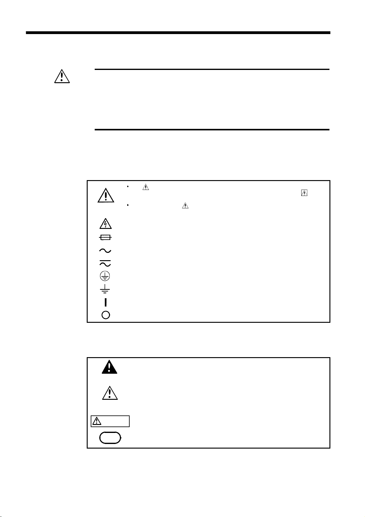
Safety Symbols
The symbol printed on the product indicates that the user should
refer to a corresponding topic in the manual (marked with the
symbol) before using the relevant function.
In the manual, the symbol indicates particularly important
information that the user should read before using the product.
Indicates that dangerous voltage may be present at this terminal.
Indicates a fuse.
Indicates AC (Alternating Current).
Indicates both DC (Direct Current) and AC (Alternating Current).
Indicates a protective conductor terminal.
Indicates a grounding terminal.
Indicates the ON side of the power switch.
Indicates the OFF side of the power switch.
The following symbols in this manual indicate the relative importance of
cautions and warnings.
Indicates that incorrect operation presents an extreme hazard that
DANGER
WARNING
could result in serious injury or death to the user.
Indicates that incorrect operation presents a significant hazard that
could result in serious injury or death to the user.
CAUTION
NOTE
______________________________________________________________________________________________
Indicates that incorrect operation presents a possibility of injury to
the user or damage to the product.
Advisory items related to performance or correct operation of the
product.
_____________________________________________________________________________________________
iii
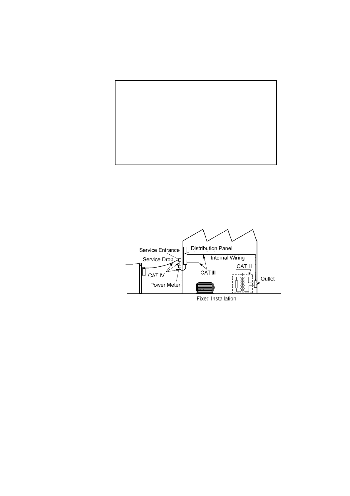
Measurement categories
To ensure safe operation of measurement products, IEC 61010 establishes
safety standards for various electrical environments, categorized as CAT II to
CAT IV, and called measurement categories.
CAT II
CAT III
CAT IV
Primary electrical circuits in equipment connected to
an AC electrical outlet by a power cord (portable
tools, household appliances, etc.)
CAT II covers directly measuring electrical outlet
receptacles.
Primary electrical circuits of heavy equipment (fixed
installations) connected directly to the distribution
panel, and feeders from the distribution panel to
outlets.
The circuit from the service drop to the service
entrance, and to the power meter and primary
overcurrent protection device (distribution panel).
Using a measurement product in an environment designated with a highernumbered category than that for which the product is rated could result in a
severe accident, and must be carefully avoided.
Use of a measurement instrument that is not CAT-rated in CAT II to CAT
IV measurement applications could result in a severe accident, and must be
carefully avoided.
______________________________________________________________________________________________

iv
_____________________________________________________________________________________________
Accuracy
The specifications in this manual include figures for "measurement accuracy"
when referring to digital measuring instruments, and for "measurement
tolerance" when referring to analog instruments.
f.s.
rdg.
dgt.
(maximum display or scale value, or length of scale)
Signifies the maximum display (scale) value or the length of the scale
(in cases where the scale consists of unequal increments or where the
maximum value cannot be defined).
In general, this is the range value (the value written on the range
selector or equivalent) currently in use.
(displayed or indicated value)
This signifies the value actually being measured, i.e., the value that is
currently indicated or displayed by the measuring instrument.
(resolution)
Signifies the smallest display unit on a digital measuring instrument,
i.e., the value displayed when the last digit on the digital display is
"1".
______________________________________________________________________________________________
_____________________________________________________________________________________________
v
Notes on Use
Follow these precautions to ensure safe operation and to obtain the full
benefits of the various functions.
To avoid electric shock, do not remove the product's case. The internal
DANGER
WARNING
components of the product carry high voltages and may become very
hot during operation.
The vinyl shield on the 9615 H.V. TEST LEAD alligator clip is not high
voltage insulated. Do not touch when high voltage is applied.
To avoid electric shock, do not allow the product to get wet, and do not
use it when your hands are wet.
To avoid electric shock, be sure to connect the protective ground
terminal to a grounded conductor.
To avoid electrical accidents and to maintain the safety specifications
of this instrument, connect the power cord provided only to a 3-contact
(two-conductor + ground) outlet.
Before turning the product on, make sure the source voltage matches
that indicated on the product's power connector. Connection to an
improper supply voltage may damage the product and present an
electrical hazard.
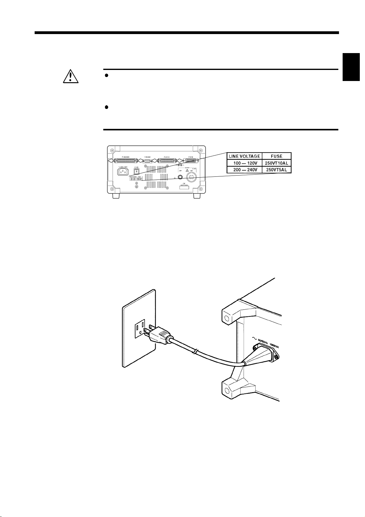
Replace the fuse only with one of the specified characteristics and
voltage and current ratings. Using a non-specified fuse or shorting the
fuse holder may cause a life-threatening hazard.
Fuse type: 250VT10AL (100-120 V), 250VT5AL (200-240 V)
To avoid electric shock when measuring live lines, wear appropriate
protective gear, such as insulated rubber gloves, boots and a safety helmet.
CAUTION
NOTE
To avoid electrocution, turn off the power to all devices before plugging or
unplugging any of the interface connectors.
To avoid damaging the power cord, grasp the plug, not the cord, when
unplugging the cord from the power outlet.
To avoid damaging H.V. TEST LEAD, do not kink or pull on the leads.
For safety reasons, when taking measurements, only use the 9615 H.V.
TEST LEAD provided with the product.
To avoid damage to the product, protect it from vibration or shock during
transport and handling, and be especially careful to avoid dropping.
Failure to observe the following precaution may result in bodily injury.
This instrument weighs approximately 18kg. When lifting or moving the
unit, it is strongly recommended that two capable persons hold the
instrument at both ends of the bottom to prevent drop or damage.
The instrument is heavy. When transporting it, follow your company's
workplace safety standards to assure safety (for example, by wearing non-
slip gloves and protective footwear).
To avoid electric shock, do not exceed the lower of the ratings shown on the
instrument and test leads.
Do not use the product near a device that generates a strong electromagnetic field or
electrostatic charge, as these may cause erroneous measurements.
This product may cause interference if used in residential areas. Such use
must be avoided unless the user takes special measures to reduce
electromagnetic emissions to prevent interference to the reception of radio
and television broadcasts.
______________________________________________________________________________________________

vi
_____________________________________________________________________________________________
Chapter Summary
Chapter 1 Overview
Describes an overview, features, and the names and functions of the parts of
the product.
Chapter 2 Testing Arrangements
Describes particulars of testing arrangements.
Chapter 3 Withstand Voltage Mode Testing Method
Describes the procedures for setting the withstand-voltage mode testing,
testing method, and test decisions.
Chapter 4 Insulation Resistance Mode Testing Method
Describes the procedures for setting the insulation-resistance mode testing,
testing method, and test decisions.
Chapter 5 Auto Test Mode Testing Method
Describes the procedures for setting the auto test mode testing, testing
method, and test decisions.
Chapter 6 Program Mode Testing Method
Describes the procedures for setting the program mode testing, testing
method, and test decisions.
Chapter 7 Optional Functions
Describes procedures for setting optional functions.
Chapter 8 Saving/Loading Preset Values
Describes procedure for saving and loading test values.
Chapter 9 External Interface
Describes use of the external I/O, and buzzer.
Chapter 10 PC Interface
Describes communication procedures and commands for an RS-232C/GP-IB
interface.
Chapter 11 Specifications
Contains the unit specifications such as the general specifications,
measurement accuracy, etc. of the unit.
Chapter 12 Maintenance and Inspection
Covers the maintenance and inspection, fuse replacement, ultimate disposal,
and system reset.
Appendix
Covers the options of the unit.
______________________________________________________________________________________________

_____________________________________________________________________________________________
1
Chapter 1
1
2
1.1 Product Introduction
(1) Easy testing conforming to standards
With the unit insulation-resistance and withstand-voltage tests based on a
wide variety of standards can be performed. Accurate test results can be
obtained by comparative screening functions that use upper- and lower-limit
values, timer functions, and ramp up/down timer functions that control testvoltage increases/decreases.
(2) Automatic insulation-resistance testing and withstand-voltage
testing
The Continuous Test mode allows consecutive insulation-resistance and
withstand-voltage tests to be performed.
Overview
3
4
5
6
7
8
9
(3) Fluorescent indicator
The large, easy-to-read fluorescent display permits quick checking of the
testing state and result.
(4) Analog Voltage Measurement
The voltage is digitally displayed on the fluorescent indicator. This value can
also be checked on the analog voltmeter.
(5) Saving testing set values (Memory function)
This unit is provided with a function for saving the set values used in a test,
allowing quick switching between different testing set values to meet a
variety of standards and regulations. Up to 10 values may be saved for each
test mode (withstand-voltage mode or insulation-resistance mode). The
values immediately prior to a power shutdown are saved in the unit, and the
unit restarts with these settings the next time.
10
11
12
13
14
A
______________________________________________________________________________________________
1.1 Product Introduction

2
_____________________________________________________________________________________________
(6) REMOTE CONTROL BOX
The 9613 REMOTE CONTROL BOX (single-hand) or the 9614 REMOTE
CONTROL BOX (dual-hand) can be connected to the external switch
terminal to perform 3153 start/stop control.
(7) External I/O
The external I/O terminal generates signals according to the state of the
3153. It can be used to feed signals for the
START
and
STOP
key.
(8) RS-232C/GP-IB interface as a standard feature
Automatic testing and saving of the test results are possible with the use of a
computer.
(9) Program test
Withstand-voltage and insulation-resistance tests under various conditions
can be conducted successively at your option. Through the use of a 3930
HIGH VOLTAGE SCANNER, many test points can be tested at one time.
Up to 32 files can be created, with each file containing up to 50 steps.
(10) Switching-power-supply method
The adoption of the PWM switching power supply allows the unit to output
any preset voltage. The test voltage is not affected by fluctuations in the
power-supply voltage of this unit.
______________________________________________________________________________________________
1.1 Product Introduction
_____________________________________________________________________________________________
3
1.2 Names and Functions of Parts
1
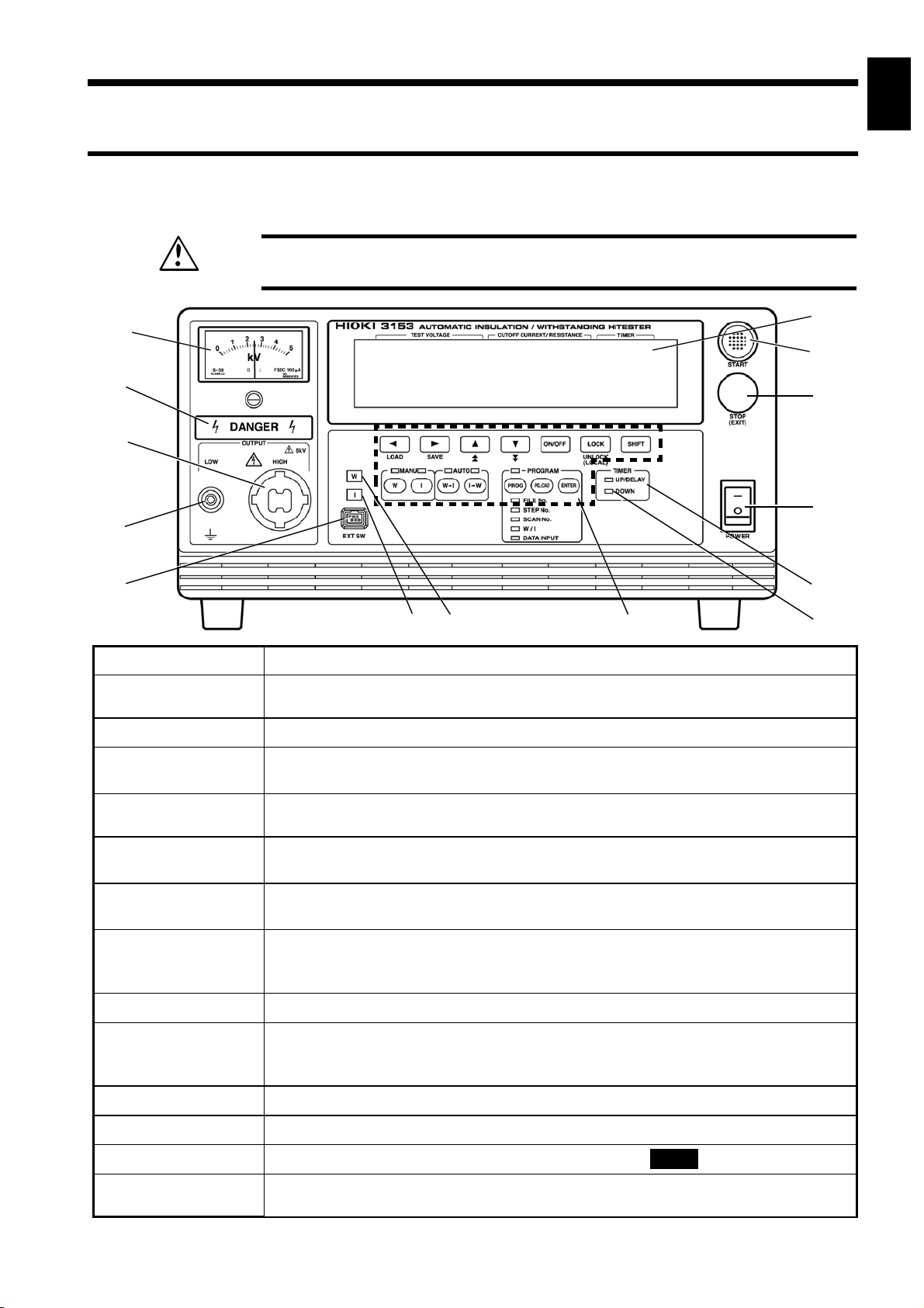
1.2.1 Front panel
To prevent electric shock, when the
WARNING
1
2
3
4
5
HIGH or LOW terminals, H.V. TEST LEAD, or the tested object.
2
DANGER
lamp is lit, never touch the
14
13
12
3
4
5
6
11
7
10
6
7
8
9
8
1 Analog voltmeter
2
DANGER lamp
3 HIGH terminal
4 LOW terminal
5 External switch
terminal
6 I lamp
7 W lamp
8 Rubber keys
9 DOWN lamp
10 UP/DELAY
lamp
11 Main power switch
Indicates output-voltage value.
This lamp lights to warn that voltage is present between the terminals during
testing.
The HIGH terminal is a high-voltage terminal for voltage outputs.
The LOW terminal is a low-voltage terminal for voltage outputs. It has the same
electric potential as the unit body.
Used for the switch signal line plug for the REMOTE CONTROL BOX.
This lamp lights when insulation-resistance mode is selected and during
insulation-resistance testing.
This lamp lights when withstand-voltage mode is selected and during withstandvoltage testing.
The 14 rubber keys include 13 function keys and a
The six function keys offer a variety of settings, used in combination with the
SHIFT
This lamp lights during ramp-down from withstand-voltage testing.
This lamp lights during ramp-up to withstand-voltage testing and during
insulation-resistance testing delays. (However, it does not light during time testing
when insulation-resistance test termination mode is set to 0 [initial setting].)
Powers the 3153 product on or off.
key.
SHIFT
key.
9
10
11
12
13
14
12 STOP key
13 START key
14 VFD (vacuum
fluorescent display)
______________________________________________________________________________________________
Normally used to terminate a test.
Used to start a test. This key functions only when the
Displays various information, such as the test state and test results.
READY
1.2 Names and Functions of Parts
lamp is lit.
A
4
_____________________________________________________________________________________________
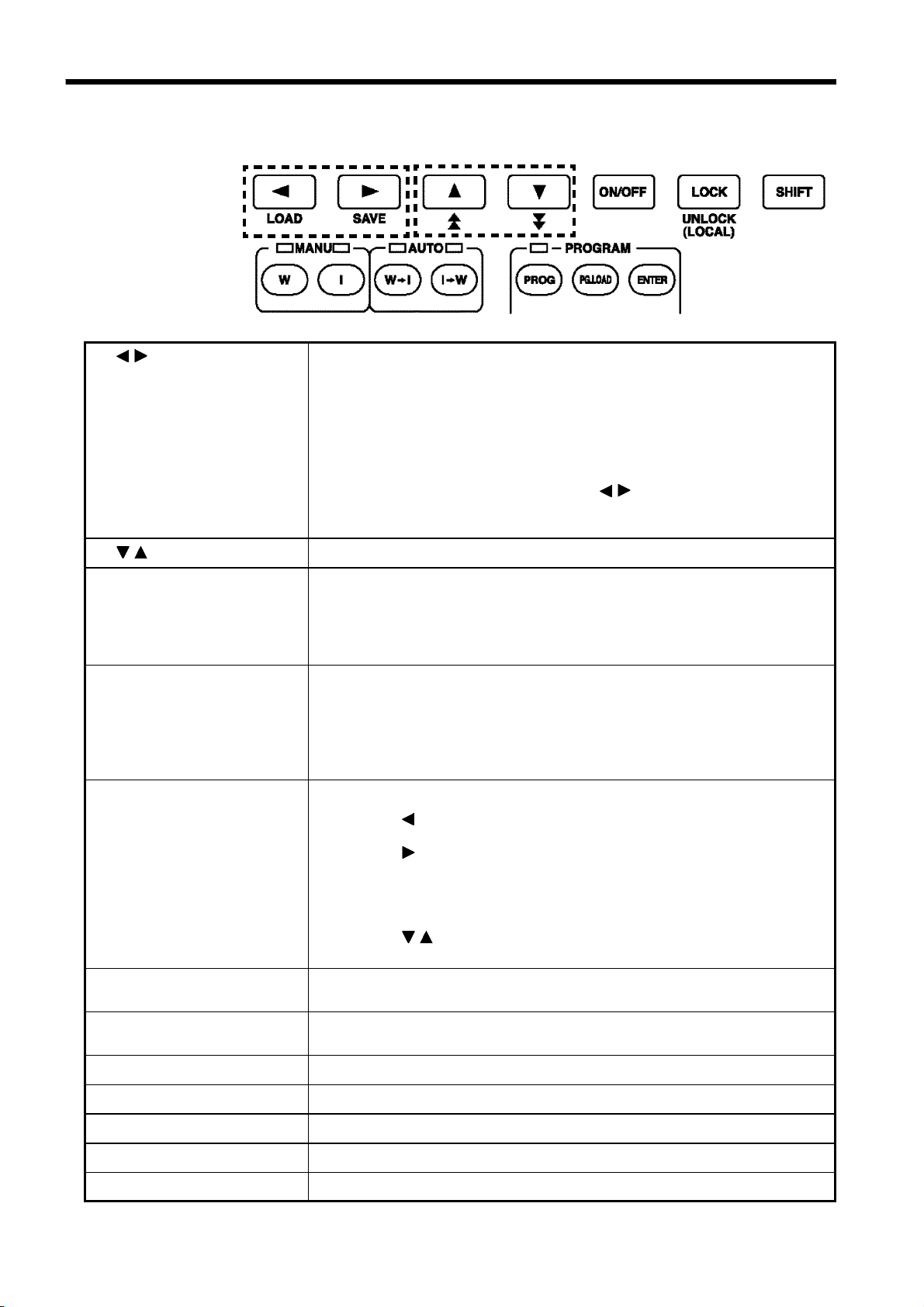
1.2.2 Rubber keys
1
/
2
/
3
ON/OFF key
key
key
1
6
7
8 9
2
10 11 12
3
4
Moves the flashing cursor.
The switching range is preset before shipment:
Withstand-voltage test:
Test-voltage value ⇔ Upper-limit value ⇔ Lower-limit value ⇔
Test time ⇔ Ramp-up time ⇔ Ramp-down time ⇔ Test-voltage type
Insulation-resistance test:
Test-voltage value ⇔ Lower-limit value ⇔ Upper-limit value ⇔
Test time ⇔ Delay time
To display the flashing cursor, press the
keys. The cursor appears,
/
displaying the preset comparative voltage value or test-voltage value.
(withstand-voltage test and insulation-resistance test)
Changes the position at which the flashing cursor appears.
Switches on/off the set value for the position of the flashing cursor. If
turned off, the set value is not used in testing.
However, the following key can't perform the switching on/off:
Withstand-voltage test: Test-voltage type, Test voltage, Upper-limit value
Insulation-resistance test: Test voltage, Lower-limit value
5
4
LOCK key
(LOCAL key)
5
SHIFT key
6
W key
(withstand-voltage test)
7
I key
(insulation-resistance test)
8
W→I key
9
I→W key
10
PROG key
Used to lock the keys.
When pressed, the
STOP
key, and Key Lock Cancel key (
LOCK
key disables all keys except the
LOCK+SHIFT
key). See the
START
key,
"Key-lock Function" section. (Chapter 3 to 6)
In the remote state, this key functions as a
LOCAL
key. It cancels the
remote state.
Used in combination with other keys.
①
SHIFT
+ key
Displaying the Preset-data loading screen. (See Chapter 8)
②
SHIFT
+ key
Displaying the Preset-data saving screen. (See Chapter 8)
③
SHIFT+UNLOCK
key
Disabling the key lock function. Cancels the key lock. When GP-IB is
used for communication, go to LOCAL state.
④
SHIFT
+
key
/
Changing the increment size of setting values.
Performs withstand-voltage tests and settings. (See Chapter 3)
Performs insulation-resistance tests and settings. (See Chapter 4)
Tests for withstand-voltage, then insulation-resistance. (See Chapter 5)
Tests for insulation-resistance, then withstand-voltage. (See Chapter 5)
Creates or edits program tests or their files. (See Chapter 6)
11
PG.LOAD key
12
ENTER key
______________________________________________________________________________________________
1.2 Names and Functions of Parts
Used to load program data. (See Chapter 6)
Used to create or edit program test files. (See Chapter 6)
_____________________________________________________________________________________________
5
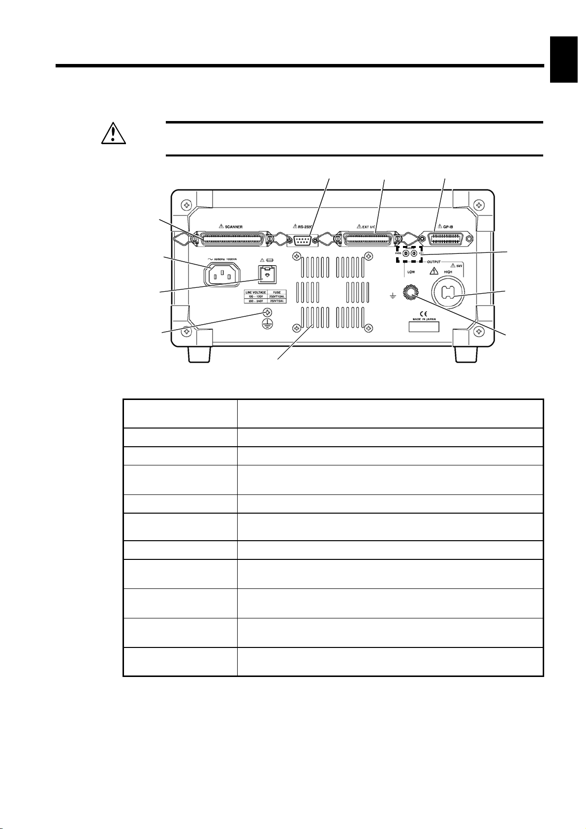
1.2.3 Rear panel
1
2
WARNING
1 Scanner connection
To prevent electric shock, when the
HIGH or LOW terminals, H.V. TEST LEAD, or the tested object.
1
2
3
4
11
terminal
Terminal for connecting the optional 3930 HIGH VOLTAGE
SCANNER. Do not connect any scanner other than the 3930.
DANGER
5 6 7
lamp is lit, never touch the
10
8
9
3
4
5
6
7
8
2 Power inlet
3 Fuse holder
4 Protective ground
terminal
5 RS-232C terminal
6 External I/O
terminal
7 GP-IB terminal
8 HIGH terminal
9 LOW terminal
10 Buzzer adjustment
knob
11 Vent holes
Connect the grounded three-core power cord supplied here.
Contains a power fuse.
Used to earth a protective ground wire. Be sure to make grounding
connections before starting a test.
Used for remote control with RS-232C.
For output of 3153 state and input of start and stop signals.
Used for remote control with GP-IB.
A high-voltage terminal for voltage output. Connected to the
HIGH terminal on the front panel.
A low-voltage terminal for voltage output. Contains the same
electrical potential as this units casing.
Used for buzzer sound adjustment. Two knobs are provided: one
for PASS screening and one for FAIL screening.
Holes for cooling the inside of the unit. Both sides of the unit also
have vent holes.
9
10
11
12
13
14
______________________________________________________________________________________________
1.2 Names and Functions of Parts
A
6
_____________________________________________________________________________________________
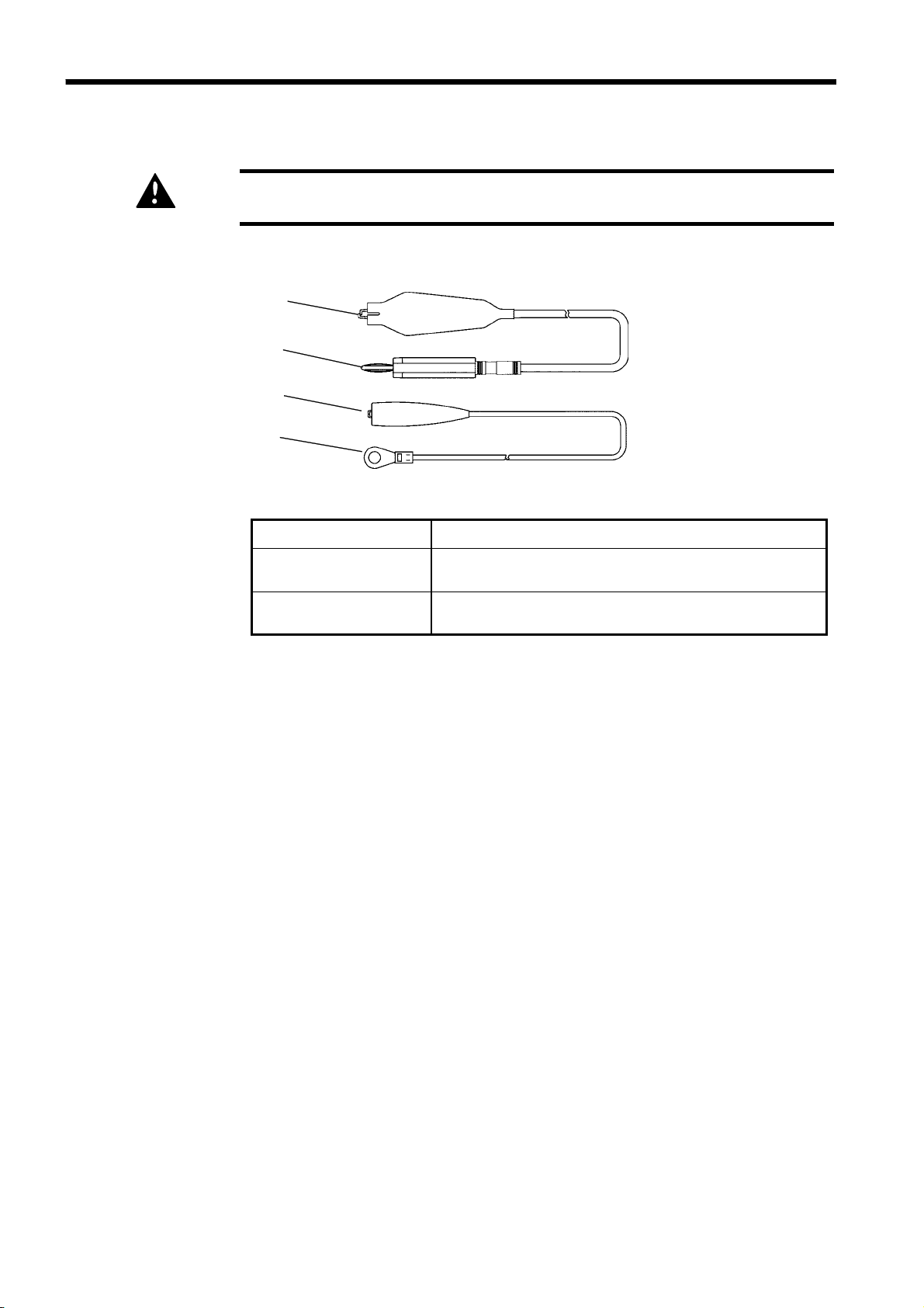
1.2.4 9615 H.V. TEST LEAD
The vinyl shield on the 9615 H.V. TEST LEAD alligator clip is not high
DANGER
voltage insulated. Do not touch when high voltage is applied.
1
High-voltage side (red)
2
1
Low-voltage side (black)
3
1 Alligator clip
2 High-voltage output
plug
3 Low-voltage output
plug
Connect to a test point on the tested object.
Connect to the HIGH terminal on the unit.
Connect to the LOW terminal on the unit.
______________________________________________________________________________________________
1.2 Names and Functions of Parts
_____________________________________________________________________________________________
7
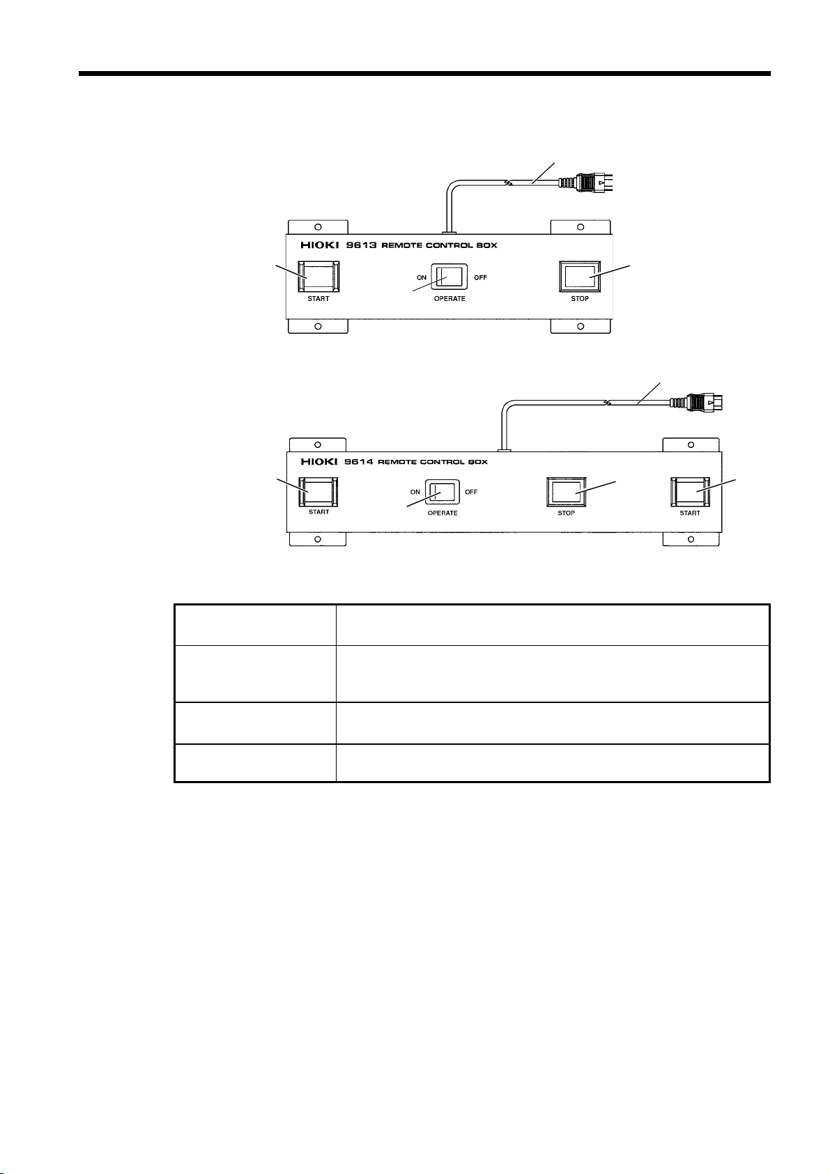
1.2.5 REMOTE CONTROL BOX
9613 REMOTE CONTROL BOX (SINGLE)
2
1
9614 REMOTE CONTROL BOX (DUAL)
2
1
4
3
4
3
2
1 OPERATE switch
2 START key
3 STOP key
4 Switch signal-line
plug
Used to enable remote-control operation. When this switch is ON,
the
START
Works in the same manner as the
the 9614 REMOTE CONTROL BOX (dual-hand), the two
and
STOP
keys for remote control are active.
START
key on the unit. With
START
switches must be pressed.
Works in the same manner as the
STOP
key is ON during a test or when a voltage is being output.
STOP
key on the unit. The
Connect to the external switch terminal on the unit.
______________________________________________________________________________________________
1.2 Names and Functions of Parts
8
_____________________________________________________________________________________________
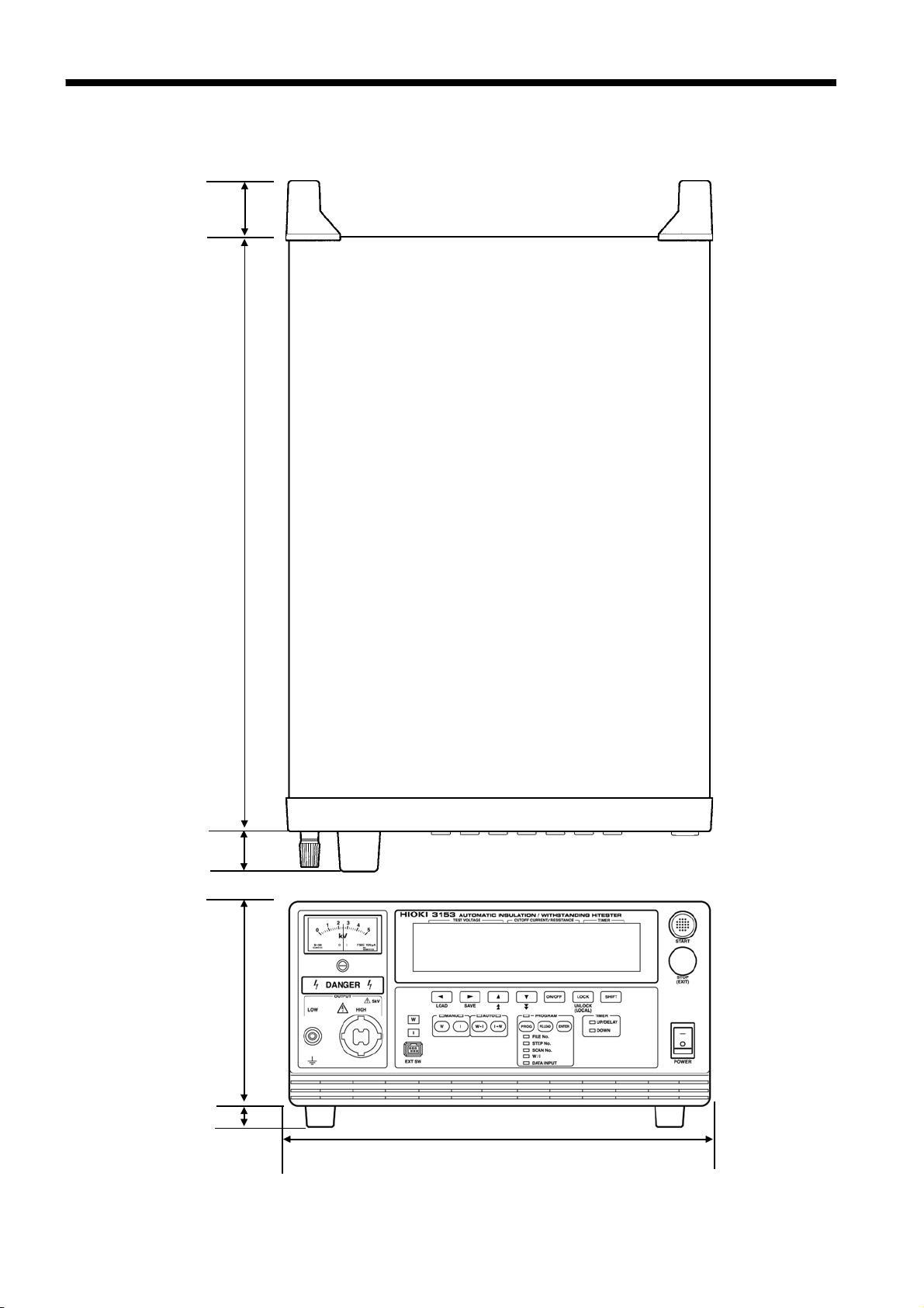
1.3 External Dimensions
m
m
1
±
2
4
m
m
2
±
0
8
4
m
m
1
±
0
3
m
m
2
±
5
5
1
m
m
1
±
6
1
320±2 mm
______________________________________________________________________________________________
1.3 External Dimensions

_____________________________________________________________________________________________
9
Chapter 2
1
2
Testing Arrangements
2.1 Connecting the Protective Ground Terminal
To avoid electric shock, be sure to connect the protective ground
WARNING
terminal to a grounded conductor.
To avoid electric shock, connect the protective ground terminal to a
grounded conductor before making any other connections.
1. Using a Phillips-head screwdriver, remove the protective ground terminal
from the rear of the unit.
2. Connect an electric wire with a sufficient current capacity to the
protective ground terminal, and secure the wire using a Phillips-head
screwdriver.
3
4
5
6
7
8
9
NOTE
3. Ground the other end of the wire.
10
11
12
13
14
A
If the ground-type double-pole power cord that is supplied with the unit is used, the
unit is automatically grounded.
______________________________________________________________________________________________
2.1 Connecting the Protective Ground Terminal
10
(
)
_____________________________________________________________________________________________
2.2 Wearing rubber gloves
To avoid any life-threatening electric shock accidents, ensure that the
DANGER
following rules are observed.
The AC Withstanding HiTester is a dangerous product which
・
discharges high voltages. To prevent getting electrocuted, always
wear high-voltage protective rubber gloves when carrying out any
operation.
Be careful when using the product and ensure that you do not touch
・
this product, any tested object that is connected or any H.V. Test
Lead, etc.
1. To avoid electrocution, always wear high-voltage protective rubber gloves
when using this product.
2. Contact your dealer or Hioki representative to help you look for high-
voltage protective rubber gloves.
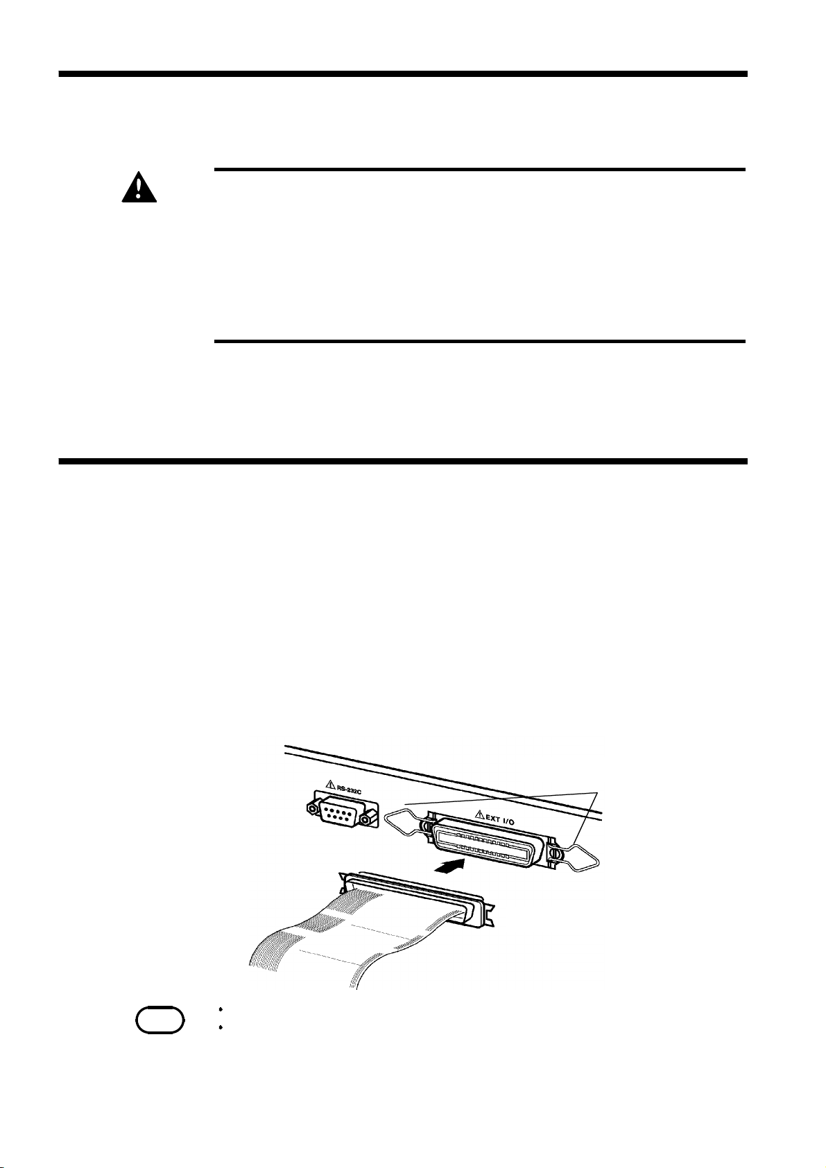
2.3 Connecting the External I/O Connector
Connect the external I/O connector before turning on the power. If the
external I/O connector is installed or removed following startup, malfunction
may result.
1. Insert the external I/O connector into the external I/O terminal.
2. Secure the external I/O connector using the hooks of the external I/O
terminal.
Hook of the external I/O terminal
External I/O connector
NOTE
______________________________________________________________________________________________
2.3 Connecting the External I/O Connector
For the specifications of the external I/O connector, see Section 9.1.
If the optional "Interlock" function is set to "1: Set," set Pin 10 of the external I/O
terminal to "LOW level" before starting a test. "
"LOW level" is set.
See Section 9.1.4
Err 000
" will be indicated until
_____________________________________________________________________________________________
11
2.4 Power Cord Connection
Before turning the product on, make sure the source voltage matches
WARNING
that indicated on the product's power connector. Connection to an
improper supply voltage may damage the product and present an
electrical hazard.
To avoid electrical accidents and to maintain the safety specifications
of this instrument, connect the power cord provided only to a 3contact (two-conductor + ground) outlet.
Supply voltage indicated on the rear panel
1
2
3
4
5
6
1. Be sure that the main power switch is turned to OFF.
2. Connect the grounded three-core power cord provided to the power inlet
on the back of the unit.
3. Insert the plug into the grounded outlet.
3
2
7
8
9
10
11
12
______________________________________________________________________________________________
2.4 Power Cord Connection
13
14
A
12
p
_____________________________________________________________________________________________
2.5 Powering On and Off the Unit
Before turning on the power, make sure that the voltage of the power
WARNING
supply being used matches the supply voltage indicated on the rear
panel of the unit. If an attempt is made to use an improper supply
voltage, there is danger of damage to this unit and of life-threatening
risk to the operator. Apply a voltage within the acceptable powervoltage range. Otherwise, damage to the unit or electrical accidents
may result.
NOTE
The settings immediately prior to power shutdown are saved. The unit restarts
with these settings, even following a power interruption. When settings are
modified, however they are only saved after running a test.
Allow 10 minutes warming up after powering on.
The REMOTE CONTROL BOX, external I/O device, RS-232C interface, and GPIB interface are active only when they are connected prior to startup. If these
devices are connected after the power is turned on, the protective function may be
activated, thus causing a malfunction.
A filter circuit is provided in the first stage of the power supply. Therefore, power
(apparent power) is consumed even when the main power switch is turned OFF,
rovided that the unit is connected to an outlet.
2
50 Hz (Effective voltage)
60 Hz (Effective voltage)
x 1.4 x 10⁻³(VA)
2
x 1.7 x 10-3(VA)
______________________________________________________________________________________________
2.5 Powering On and Off the Unit
_____________________________________________________________________________________________
13
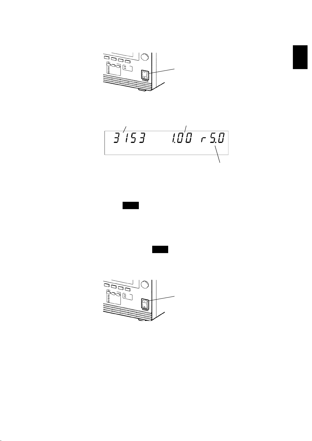
(1) Powering on the unit
1. Turn the main power switch to ON
2. The model name and version number are displayed as below:
Software version
Model name
"Version 1.00" is displayed.
(l)
.
Main power switch
Interface
"RS-232C 9600 bps" is displayed.
"rS.0" :RS-232C 9600 bps
"rS.1" :RS-232C 19200 bps
"G.XX" :GP-IB address XX
1
2
3
4
5
6
7
3. When the
mode), the keys are ready for operation. (See Section 7.5)
(2) Powering off the unit
1. Following a test, make sure the analog voltmeter is at 0 kV, the
lamp is OFF, and the
2. Turn OFF the Main Power switch.
READY
lamp is lit (it does not light up in the Double Action
READY
lamp is lit.
Main power switch
8
9
DANGER
10
11
12
13
______________________________________________________________________________________________
2.5 Powering On and Off the Unit
14
A
14
_____________________________________________________________________________________________
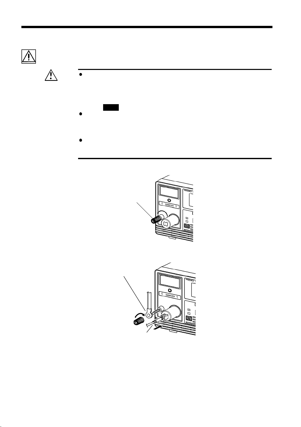
2.6 Connecting the 9615 H.V. TEST LEAD
To prevent electrical shock, turn off the power unit, make sure that
WARNING
there is no high voltage being applied to the output, confirm the
following 3 items, and connect the 9615 H.V. TEST LEAD.
(1) The analog voltmeter reads 0 kV.
(2) The
(3) The
Before connecting the 9615 H.V. TEST LEAD, be sure to check its
insulation for tearing and metal exposure.Using the product in such
conditions could cause an electric shock, so contact your dealer or
Hioki representative for repair.
To avoid electric shock, make sure the 9615 H.V. TEST LEAD is
securely connected before starting a test, as a loose test lead can
cause a hazard when a voltage is output.
DANGER
READY
lamp is OFF.
lamp is lit (it is off in the Double Action mode).
1. Remove the LOW terminal by turning it counterclockwise.
Low terminal
2. As shown in the figure, insert the plug on the H.V. TEST LEAD (low
voltage side).
Plug on the H.V. TEST LEAD
(low voltage side)
3. Secure the LOW terminal by turning it clockwise.
4. Connect the plug on the H.V. TEST LEAD (high voltage side) to the
HIGH terminal.
______________________________________________________________________________________________
2.6 Connecting the 9615 H.V. TEST LEAD
_____________________________________________________________________________________________
15
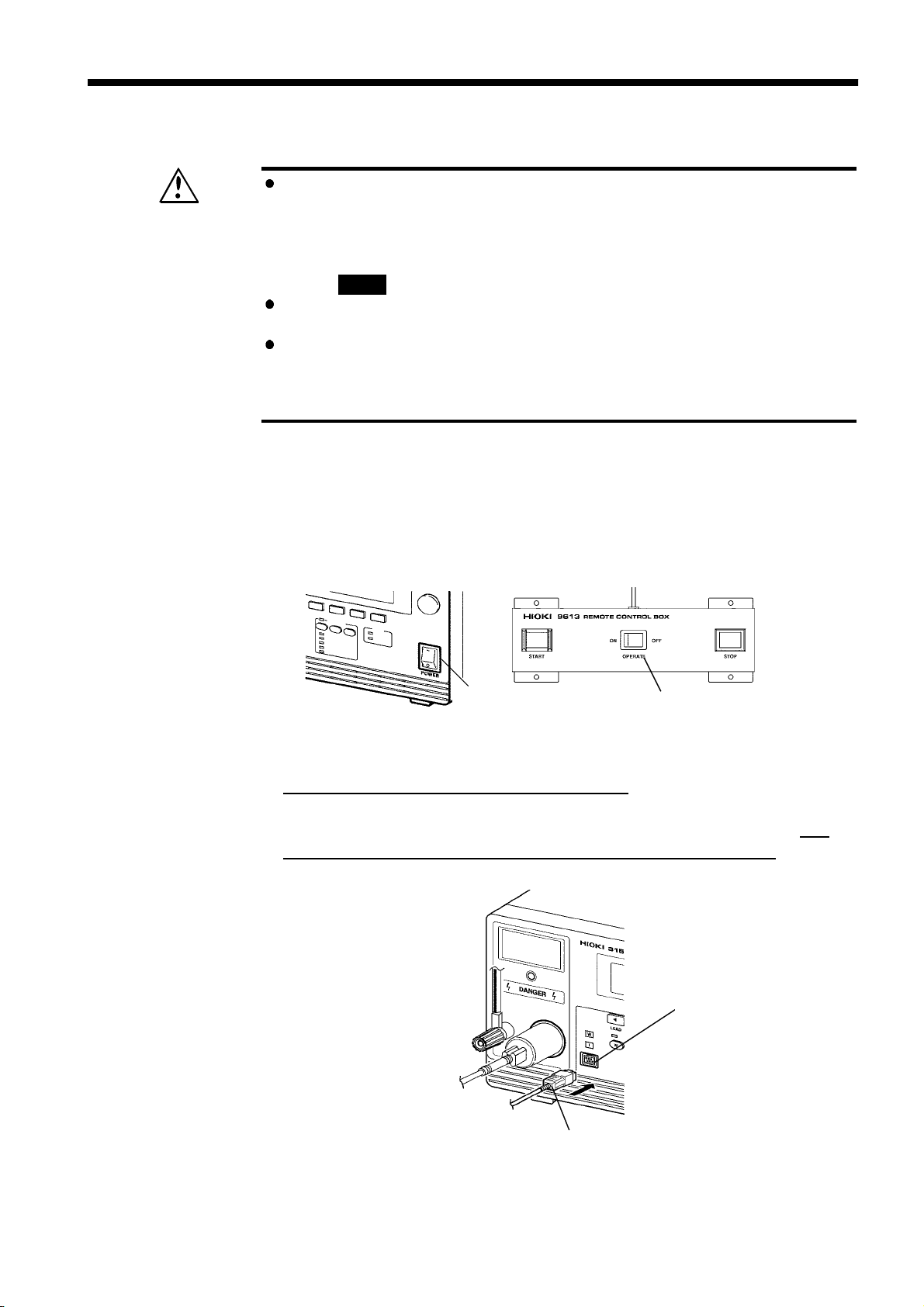
2.7 Connecting the REMOTE CONTROL BOX
To prevent electrical shock, turn off the power unit, make sure that
WARNING
there is no high voltage being applied to the output, confirm the
following 3 items, and connect the 9615 H.V. TEST LEAD.
(1) The analog voltmeter reads 0 kV.
(2) The
(3) The
DANGER
READY
lamp is OFF.
lamp is lit (it is off in the Double Action mode).
To prevent malfunctions, do not remove the REMOTE CONTROL BOX
following startup. Before removing it, be sure to turn OFF the power.
To avoid electric shock, when using the REMOTE CONTROL BOX,
provide safety measures to keep the output-voltage terminal, tested
object, and H.V. TEST LEAD out of contact with one another when
they are in the TEST state.
Connection of the REMOTE CONTROL BOX (9613/9614) enables start/stop
operations to be performed easily.
1. Make sure the Main Power switch and OPERATE switch on the
REMOTE CONTROL BOX are OFF.
Main power switch
OPERATE switch on the
REMOTE CONTROL BOX
2. Insert the switch signal-line plug into the external switch terminal.
Check the direction of the switch signal line.
3. Turn ON the
OPERATE
switch can be turned ON/OFF even following startup.
OPERATE
switch of the REMOTE CONTROL BOX. The
External switch terminal
Switch signal-line plug
______________________________________________________________________________________________
2.7 Connecting the REMOTE CONTROL BOX
16
,
_____________________________________________________________________________________________
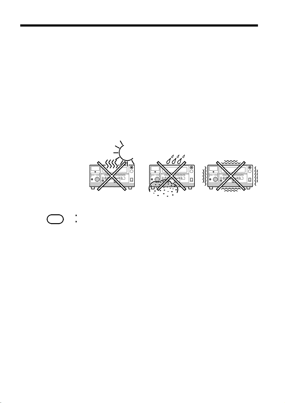
2.8 Installation of the Unit
Temperature: 0 to 40
℃
Humidity: 80% RH or less (no condensation)
Avoid the following locations:
・
Subject to direct sunlight.
・
Subject to high levels of dust, steam, or corrosive gases (Avoid using the
equipment in an environment containing corrosive gases (e.g., H2S, SO2,
NI2,andCI2) or substances that generate harmful gasses (e.g., organic
silicones, cyanides, and formalins)).
・
Subject to vibrations.
・
In the vicinity of equipment generating strong electromagnetic fields.
NOTE
The noise generated by this unit may affect equipment located around the unit.
Install the unit in such a way that the vent holes on both sides and at the rear of
the unit are not blocked
so that the unit can function normally.
______________________________________________________________________________________________
2.8 Installation of the Unit
_____________________________________________________________________________________________
p
17
2.9 Connection to the Measured Equipment
Observe the following precautions to avoid electric shock.
DANGER
Make sure that no high voltage is being applied to the output, confirm
the following items, and connect the H.V. TEST LEAD.
(1) The analog voltmeter reads 0 kV.
(2) The
(3) The
In the TEST state, never touch the output-voltage terminal, H.V. TEST
LEAD, or tested object.
Even following a test, there may be a residual voltage at the output
terminal. Therefore, before touching the output-voltage terminal, H.V.
TEST LEAD, or tested object, make sure that no high voltage is being
applied between the output terminals.
DANGER
READY
lamp is OFF.
lamp is lit (it is off in the Double Action mode).
NOTE
1. Make sure the analog voltmeter is at 0 kV and the
2. Make sure the unit is in the READY state with the
DANGER
READY
lamp is OFF.
lamp ON (it is
OFF in the Double Action mode).
3. Connect the LOW terminal probe to the tested object. Fasten the probe
securely to prevent it from loosening during a test.
4. Following the procedure described above, connect the HIGH terminal
probe to the tested object.
Note that taking measurements or routing cables in a humid location may cause
errors in insulation-resistance tests.
If the HIGH and LOW voltage output terminals short-circuit or a dielectric
breakdown occurs in the tested object during the test, noise will be generated and
such noise may lead to a malfunction of this unit or of a nearby electronic device.
If this problem occurs, connect a ferrite core or a resistor to the H. V. TEST
LEAD (high voltage side).
When using a resistor, choose one appropriate for the power rating and withstand
voltage. Also, be alert to any drop in test voltage.
Beware of electric shock when connecting the resistor.
Do not the test lead and the EXT/IO cable arranged closely to each other.
Doing so may lead to a malfunction of the external control due to a noise.
Additionally, if the test lead touches to other metallic parts, it may cause an
increase in leakage current.
Prevent the test lead from coming into contact with other parts as much as
ossible.
______________________________________________________________________________________________
2.9 Connection to the Measured Equipment
 Loading...